

Installation Instructions
NOTE: Read the entire instruction manual before starting the
installation.
NOTE: Installer: Make sure the Owner's Manual and Service
Instructions are left with the unit after installation,
TABLE OF CONTENTS
PAGE
SAFETY CONSIDERATIONS ......................... 2
INTRODUCTION ................................... 2
RECEIVING AND INSTALLATION .................. 2-8
Check Equipment .................................. 2
Identify Unit .................................... 2
Inspect Shipment ................................. 2
Provide Unit Support ............................... 2
Slab Mount ..................................... 2
Ground Mount .................................. 2
Provide Clearances ................................. 2
Place Unit ........................................ 2
Select and Install Ductwork ........................... 3
Installing factory-supplied duct flanges ............... 3
Configuring Units for Downflow (Vertical) Discharge .... 7
Connect Condensate Drain ........................... 7
Install Electrical Connections ......................... 7
High-Voltage Connections ......................... 7
Routing Power Leads Into Unit ...................... 7
Connecting Ground Lead to Unit Ground .............. 8
Routing Control Power Wires ...................... 8
Accessory Electric Heat Wiring ...................... 8
PRE-START-UP .................................... 8
START-UP ...................................... 9-12
Check for Refrigerant Leaks .......................... 9
Start-Up Cooling and Make Adjustments ................ 9
Checking Cooling and Heating Control Operation ....... 9
Refrigerant Charge ................................. 9
No Charge ...................................... 9
Low Charge Cooling .............................. 9
Heating Mode Charge ............................ 10
Indoor Airflow and Airflow Adjustments ............... 12
Sequence of Operation ............................. 12
Fan Operation .................................. 12
Cooling Operation ............................... 12
Heating Operation ............................... 12
Continuous Fan ................................. 12
Defrost ....................................... 12
Electric Resistance Heating ........................ 12
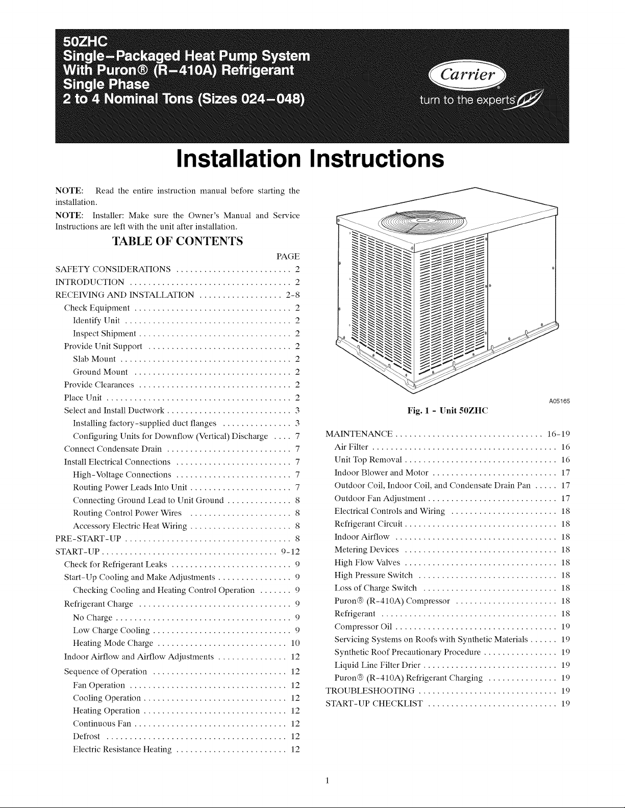
A05165
Fig. 1 - Unit 50ZHC
MAINTENANCE ................................ 16-19
Air Filter ........................................ 16
Unit Top Removal ................................. 16
Indoor Blower and Motor ........................... 17
Outdoor Coil, Indoor Coil, and Condensate Drain Pan ..... 17
Outdoor Fan Adjustment ............................ 17
Electrical Controls and Wiring ....................... 18
Refrigerant Circuit ................................. 18
Indoor Airflow ................................... 18
Metering Devices ................................. 18
High Flow Valves ................................. 18
High Pressure Switch .............................. 18
Loss of Charge Switch ............................. 18
Puron® (R-410A) Compressor ...................... 18
Refrigerant ...................................... 18
Compressor Oil ................................... 19
Servicing Systems on Roofs with Synthetic Materials ...... 19
Synthetic Roof Precautionary Procedure ................ 19
Liquid Line Filter Drier ............................. 19
Puron® (R-410A) Refrigerant Charging ............... 19
TROUBLESHOOTING .............................. 19
START-UP CHECKLIST ............................ 19
SAFETY CONSIDERATIONS
Installation and servicing of this equipment can be hazardous due
to mechanical and electrical components. Only trained and
qualified personnel should install, repair, or service this equipment.
Untrained personnel can perform basic maintenance functions such
as cleaning and replacing air filters. All other operations must be
performed by trained service personnel. When working on this
equipment, observe precautions in the literature, on tags, and on
labels attached to or shipped with the unit and other safety
precautions that may apply.
Follow all safety codes. Wear safety glasses, protective clothing,
and work gloves. Use quenching cloth for brazing operations.
Have fire extinguisher available. Read these instructions
thoroughly and follow all warnings or cautions included in
literature and attached to the unit. Consult local building codes,
the current editions of the National Electrical Code (NEC) NFPA
70 and NFPA 90B-Installation Warm Air Heating and A/C
Systems (Residential). In Canada refer to the current editions of the
Canadian Electrical Code CSA C22.1.
Recognize safety information. This is the safety-alert symbol Z_
When you see this symbol on the unit and in instructions or manu-
als, be alert to the potential for personal iniury. Understand these
signal words: DANGER, WARNING, and CAUTION. These
words are used with the safety-alert symbol. DANGER identifies
the most serious hazards which will result in severe personal iniury
or death. WARNING signifies hazards which could result in per-
sonal iniury or death. CAUTION is used to identify unsafe practic-
es which may result in minor personal injury or product and prop-
erty damage. NOTE is used to highlight suggestions which will
result in enhanced installation, reliability, or operation.
ELECTRICALSHOCK HAZARD
Failure to follow this warning could result in personal
injury or death.
Before installing or servicing system, always turn off main
power to system and install lockout tag. There may be
more than one disconnect switch. Turn off accessory heater
power switch if applicable.
CUT HAZARD
Failure to follow this caution may result in personal iniury.
Sheet metal parts may have sharp edges or burrs. Use care
and wear appropriate protective clothing, safety glasses and
gloves when handling parts and servicing.
PERSONAL INJURY AND ENVIRONMENTAL
HAZARD
Failure to relieve system pressure could result in personal
injury and/or death.
1. Relieve pressure and recover all refrigerant before
servicing existing equipment, and before final unit disposal.
Use all service ports and open all flow-control devices,
including solenoid valves.
2. Federal regulations require that you do not vent
refrigerant into the atmosphere. Recover during system
repair or final unit disposal.
INTRODUCTION
This packaged heat pump is fully self-contained and designed for
outdoor installation (See Fig. 1). Standard units are shipped in a
horizontal-discharge configuration for installation on a
ground-level slab or directly on the ground if local codes permit.
Standard units can be converted to downflow (vertical) discharge
configurations for rooftop applications with a field supplied
plenum.
RECEIVING AND INSTALLATION
Step 1 -- Check Equipment
IDENTIFY UNIT
The unit model number and serial number are printed on the unit
informative plate. Check this information against shipping papers.
INSPECT SHIPMENT
Inspect for shipping damage while unit is still on shipping pallet. If
unit appears to be damaged or is torn loose from its anchorage,
have it examined by transportation inspectors before removal.
Forward claim papers directly to transportation company.
Manufacturer is not responsible for any damage incurred in transit.
Check all items against shipping list. Immediately notify the
nearest equipment distribution office if any item is missing. To
prevent loss or damage, leave all parts in original packages until
installation.
Step 2 -- Provide Unit Support
For hurricane tie downs, contact distributor for details and PE
(Professional Engineering) Certificate, if required.
SLAB MOUNT
Place the unit on a solid, level concrete pad that is a minimum of 4
in. (102 mm) thick with 2 in. (51 mm) above grade. The slab
should extend approximately 2 in. (51 mm) beyond the casing on
all 4 sides of the unit. Do not secure the unit to the slab except
when required by local codes.
A 6-in. (152 mm) wide gravel apron should be used around the
flat surface to prevent airflow blockage by grass or shrubs. The
unit should be level within 1/4 in. (6 mm). This is necessary for the
unit drain to function properly.
GROUND MOUNT
The unit may be installed either on a slab or placed directly on the
ground if local codes permit. Place the unit on level ground
prepared with gravel for condensate discharge.
Step 3 -- Provide Clearances
The required minimum service clearances are shown in Fig. 4.
Adequate ventilation and outdoor air must be provided.
The outdoor fan draws air through the outdoor coil and discharges
it through the top fan grille. Be sure that the fan discharge does not
recirculate to the outdoor coil. Do not locate the unit in either a
corner or under an overhead obstruction. The minimum clearance
under a partial overhang (such as a normal house overhang) is 48
in. (1219 mm) above the unit top. The maximum horizontal
extension of a partial overhang must not exceed 48 in. (1219 mm).
IMPORTANT: Do not restrict outdoor airflow. An air restriction
at either the outdoor-air inlet or the fan discharge may be
detrimental to compressor life.
Do not place the unit where water, ice, or snow from an overhang
or roof will damage or flood the unit. Do not install the unit on
carpeting or other combustible materials. Slab-mounted units
should be at least 4 in. (102 mm) above the highest expected water
and runoff levels. Do not use unit if it has been under water.
Step 4 -- Place Unit
Unit can be moved with the rigging holds provided in the unit
base. Refer to Table 1 for operating weights. Use extreme caution
to prevent damage when moving the unit. Unit must remain in an
upright position during all moving operations. The unit must be
levelwithin1/4in.(6ram)forpropercondensatedrainage;the
ground-levelpadmustbelevelbeforesettingtheunitinplace.
Whenafield-fabricatedsupportisused,besurethatthesupportis
levelandthatitproperlysupportstheunit.
Step 5 -- Select and Install Ductwork
The design and installation of the duct system nmst be in
accordance with the standards of the NFPA for installation of
non-residence type air conditioning and ventilating systems,
NFPA 90A or residence type, NFPA 90B and/or local codes and
ordinances.
Select and size ductwork, supply-air registers, and return air grilles
according to ASHRAE (American Society of Heating,
Refrigeration, and Air Conditioning Engineers) recommendations.
Use the duct flanges provided on the supply- and return-air
openings on the side of the unit. See Fig. 4 for connection sizes
and locations. The 14-in. (356 mm) round or 14 x 20 in. (356 x
508 mm) rectangular duct collars are shipped inside the unit
attached to the base pan in the indoor blower compartment.
They are field-installed and must be removed from the indoor
blower compartment prior to start-up, even if they are not
used for installation. If a corrugated shipping block is used
under the blower housing, remove and discard the block and
label.
When designing and installing ductwork, consider the following:
UNIT DAMAGE HAZARD
Failure to follow this caution may result in damage to unit
components.
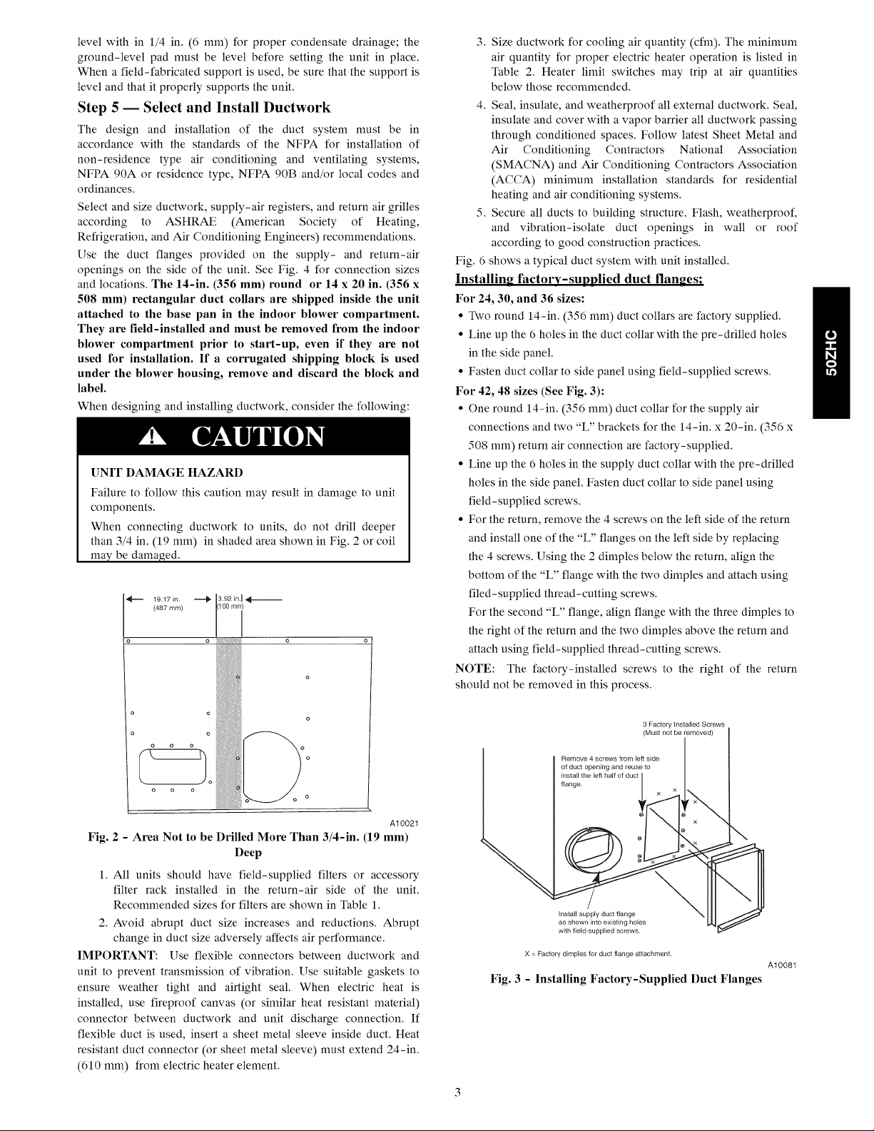
When connecting ductwork to units, do not drill deeper
than 3/4 in. (19 ram) in shaded area shown in Fig. 2 or coil
may be damaged.
(487 ram) (40O ram)
19 17in _ 3,92 in I _---
o o
3. Size ductwork for cooling air quantity (cfm). The naininmm
air quantity for proper electric heater operation is listed in
Table 2. Heater limit switches may trip at air quantities
below those recommended.
4. Seal, insulate, and weatherproof all external ductwork. Seal,
insulate and cover with a vapor barrier all ductwork passing
through conditioned spaces. Follow latest Sheet Metal and
Air Conditioning Contractors National Association
(SMACNA) and Air Conditioning Contractors Association
(ACCA) naininmm installation standards for residential
heating and air conditioning systems.
5. Secure all ducts to building structure. Flash, weatherproof,
and vibration-isolate duct openings in wall or roof
according to good construction practices.
Fig. 6 shows a typical duct system with unit installed.
Installing factory-supplied duct flanges;
For 24, 30, and 36 sizes:
• Two round 14-in. (356 ram) duct collars are factory supplied.
• Line up the 6 holes in the duct collar with the pre-drilled holes
in the side panel.
• Fasten duct collar to side panel using field-supplied screws.
For 42, 48 sizes (See Fig. 3):
• One round 14-in. (356 ram) duct collar for the supply air
connections and two "L" brackets for the 14-in. x 20-in. (356 x
508 ram) return air connection are factory-supplied.
• Line up the 6 holes in the supply duct collar with the pre-drilled
holes in the side panel. Fasten duct collar to side panel using
field-supplied screws.
• For the return, remove the 4 screws on the left side of the return
and install one of the "L" flanges on the left side by replacing
the 4 screws. Using the 2 dimples below the return, align the
bottom of the "L" flange with the two dimples and attach using
filed-supplied thread-cutting screws.
For the second "L" flange, align flange with the three dimples to
the right of the return and the two dimples above the return and
attach using field-supplied thread-cutting screws.
NOTE: The factory-installed screws to the right of the return
should not be removed in this process.
o
o
o
o
o
A10021
Fig. 2 - Area Not to be Drilled More Than 3/4-in. (19 mm)
Deep
1. All units should have field-supplied filters or accessory
filter rack installed in the return-air side of the unit.
Recommended sizes for filters are shown in Table 1.
2. Avoid abrupt duct size increases and reductions. Abrupt
change in duct size adversely affects air performance.
IMPORTANT: Use flexible connectors between ductwork and
unit to prevent transmission of vibration. Use suitable gaskets to
ensure weather tight and airtight seal. When electric heat is
installed, use fireproof canvas (or similar heat resistant material)
connector between ductwork and unit discharge connection. If
flexible duct is used, insert a sheet metal sleeve inside duct. Heat
resistant duct connector (or sheet metal sleeve) must extend 24-in.
(610 ram) from electric heater element.
3 FactoryInstalled Screws
¢
Remove 4 screws from left side
orl ?, ,h t2;%iTfr2 e.to
flange. / x ,
Install supply duct flange
as shown into existing holes
with field-supplied screws.
X = Factory dimples for duct flange attachment.
Fig. 3 - Installing Factory-Supplied Duct Flanges
A10081
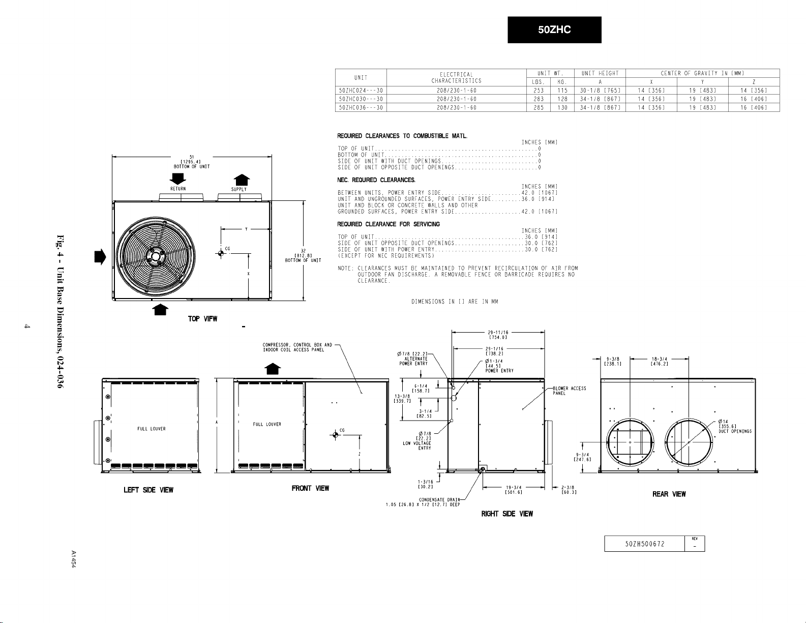
UNIT
50ZHCO24 30
50ZHC030 30
50ZHC036 30
ELECTRICAL
CHARACTERISTICS
208/230 1 60
208/230 1 60
208/230 I 60
UNIT WT.
LBS, KG
253 115
283 128
285 130
UNIT HEIGHT
A
30 1/8 [765]
34 1/8 [867]
34 1/8 [867]
CENTER OF GRAVlTv IN [MM]
X Y Z
14 [356] 19 [a83] 14 [356]
14 [356] 19 [a83] 16 [406]
14 [356] 19 [a83] 16 [406]
I
.=.
=
=
i
REQUIRED CLEARANCES TO COMBUSTIBLE MATL.
TOP OF UNIT ................................................. 0
[ 129J5_,4]
BOTTOM OF UNIT
j.
RETURN SUPPLY
I 1 i I .I
r
i
x
[8t;
BOTTOM OF UNIT
BOTTOMOF UNIT .............................................. O
SIDE OF UNIT WITH D_CT OPENINGS ............................. 0
SIDE OF UNIT OPPOSITE DUCT OPENINGS ......................... 0
NEC. REQUIRED CLEARANCE_
BETWEEN UNITS, POWER ENTRY SIDE ........................ 42 0 [I067]
UNIT AND UNGROUNDEDSURFACES, POWER ENTRY SIDE ......... 360 [914]
UNIT AND BLOCK OR CONCRETE WALLS AND OTHER
GROUNDEDSURFACES, POWERENTRY SIDE .................... 420 [I067]
REQUIRED CLEARANCE FOR SERVICING
TOP OF UNIT ............................................ 36 0 [914]
SIDE OF UNIT OPPOSITE DUCT OPENINGS ..................... 30.0 [762]
SIDE OF UNIT WITH POWER ENTRY........................... 300 [762]
[EXCEPT FOR NEC REQUIREMENTS)
NOTE: CLEARANCES MUST BE MAINTAINED TO PREVENT RECIRCULATION OF AIR FROM
OUTDOOR FAN DISCHARGE A REMOVABLE FENCE OR BARRICADE REQUIRES NO
CLEARANCE
INCHES
[MM]
INCHES [MM]
INCHES [MM]
1
t
TOP VIFW
COMPRESSOR,CONTROLBOX AND
INDOORCOILACCESSPANEL
t
.... _m
\
\
DIMENSIONS IN [] ARE IN MM
R9-11/16
¢7/8 [22.2]_ [738,2]
POWER ENTRY [4451
"TT\ /O'-
29-1/16 i
POWERENTRY
_3!,_R-,,, J__ /:_" i: "
[754.0]
PANEL
ACCESS
I!_'I1 _ _-_"
[476.2]
l
®'
i
A I
FULL LOUVER
@ FULL LOUVER
'l_iiiiiiii
n _
•'===.=='===_=. =..==
LEFT ,SIDEVIEW
FRONT VIEW
. ;[
z
1,05 [RR,8]X liR [12,7[DEEP
CONDENSATEDRAIN_
RIGHT SIDE VIEW
2-M8
[6013]
c_
50ZH500672
REAR VIEW
v
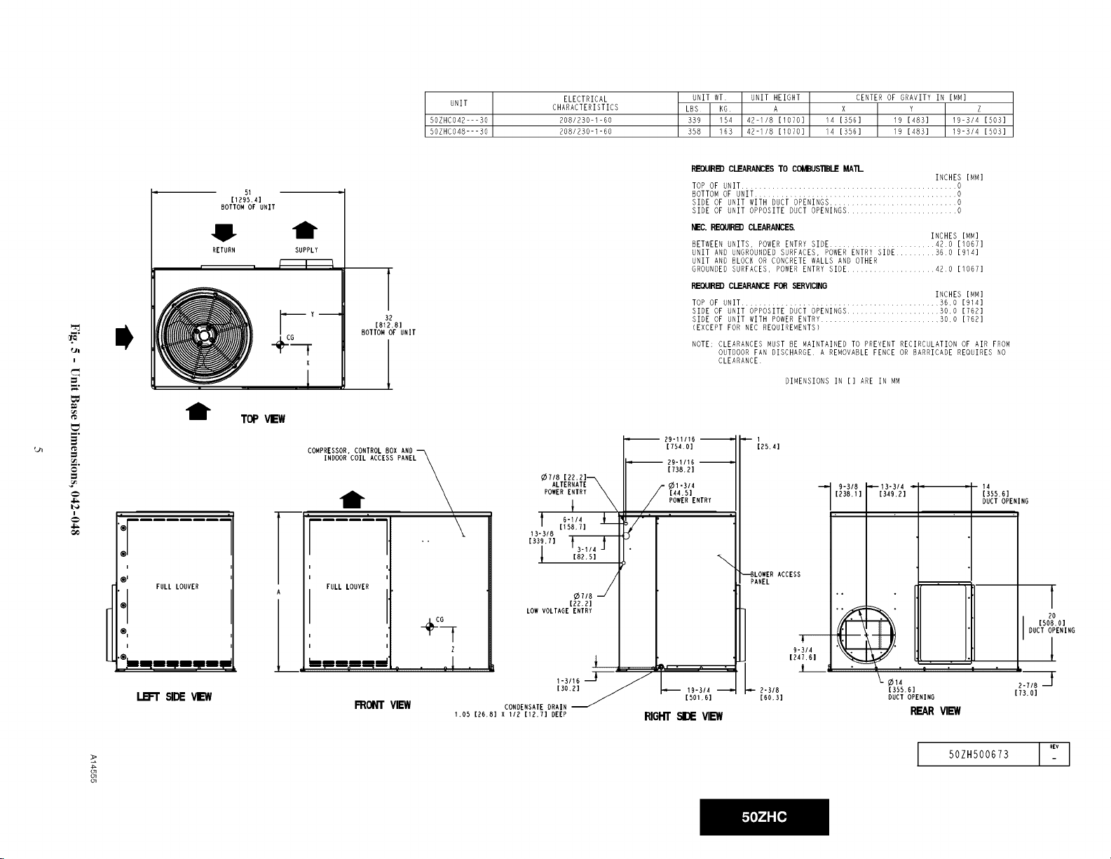
UNIT
50ZHC042---30
50ZHCO48---30
ELECTRICAL
CHARACTERISTICS
208/230-1-60
208/230-1-60
UNIT WT UNIT HEIGHT
LBS KG A
339 154 42-I/8 [I070]
358 163 42-i/8 [1070]
CENTER OF GRAVITv IN [MM]
x Y Z
14 [356] 19 [483] 19-3/4 [503]
14 [3SB] 19 [483] 19-3/4 [503]
i
,="
.=.
o
&
I
t TOP
! |
®
i
0'
'® FULLLOUVER
®,
i
[1795',4]
BOTTOM OF UNIT
t
RETURN SUPPLY
, _"-]--
x
1
COMPRESSOR,CONTROL BOX AND _ [754.0]
.,_._= : . :! . i _
REOUIR_'n CLEARANCESTO COMBUS_BLE MA'II_
TOP OF UNIT ................................................. 0
BOTTOMOF UNIT .............................................. O
SIDE OF UNIT WITH DUCT OPENINGS............................. O
SIDE OF UNIT OPPOSITE DUCT OPENINGS...................... O
NEC REOUIR_ CLEARANCE_
BETWEENUNITS, POWERENTRY SIDE ........................ 42 0 11067]
UNIT AND UNGROUNDEDSURFACES, DOWERENTRY SIDE ......... B60 19141
UNIT AND BLOCK OR CONCRETEWALLS AND OTHER
GROUNDEDSURFACES, POWERENTRY SIDE .................... 420 [I067]
REOUIRk'n CLEARANCEFOR SERVICING
TOP OF UNIT ............................................. B6.0 [914]
SIDE OF UNIT OPPOSITE DUCT OPENINGS ................... 3O.O [762]
[81;
BOTTOM OF UNIT
INDO; ACCESS PANEL_ ¢718pOwERALTERNATE\[22,21_,,EIXIRY _(//[44.5]F29-11161738.21_I.311pOWERENTRY
FULLLOUVER j
LOWVOLTAGEENTRY
l
¢7/8
[22.2]
I [82,51 " , . _ .
SIDE OF UNIT WITH POWERENTRv........................... 3O,O [762]
(EXCEPT FOR NEC REQUIREMENTS)
NOTE: CLEARANCES MUST BE MAINTAINED TO PREVENT RECIRCULATION OF AIR FROM
29-11116
FRONT VIEW CONDENSATE DRAIN _i
1.OS[26.81XI/2112. TIDEEP _GH'F_EW
INCHES [MM]
INCHES [MM]
INCHES [MM]
OUTDOORFAN DISCHARGE A REMOVABLEFENCE OR BARRICADE REQUIRES NO
CLEARANCE
DIMENSIONS IN [] ARE IN MM
1
[25.4]
13"314 : : 14
o-3_8I-'-
[349.2] [355,6]
• • DUCT OPENING
[238,t] /
"_BLOWERACCESS I
o
I"
2"3/8
EGO.B]
¢14 2"7/8 '_
[355.6] [73,0]
DUCT OPENING
REAR VIEW
[508.01
DUCT OPENING
50ZH500673 ,iv
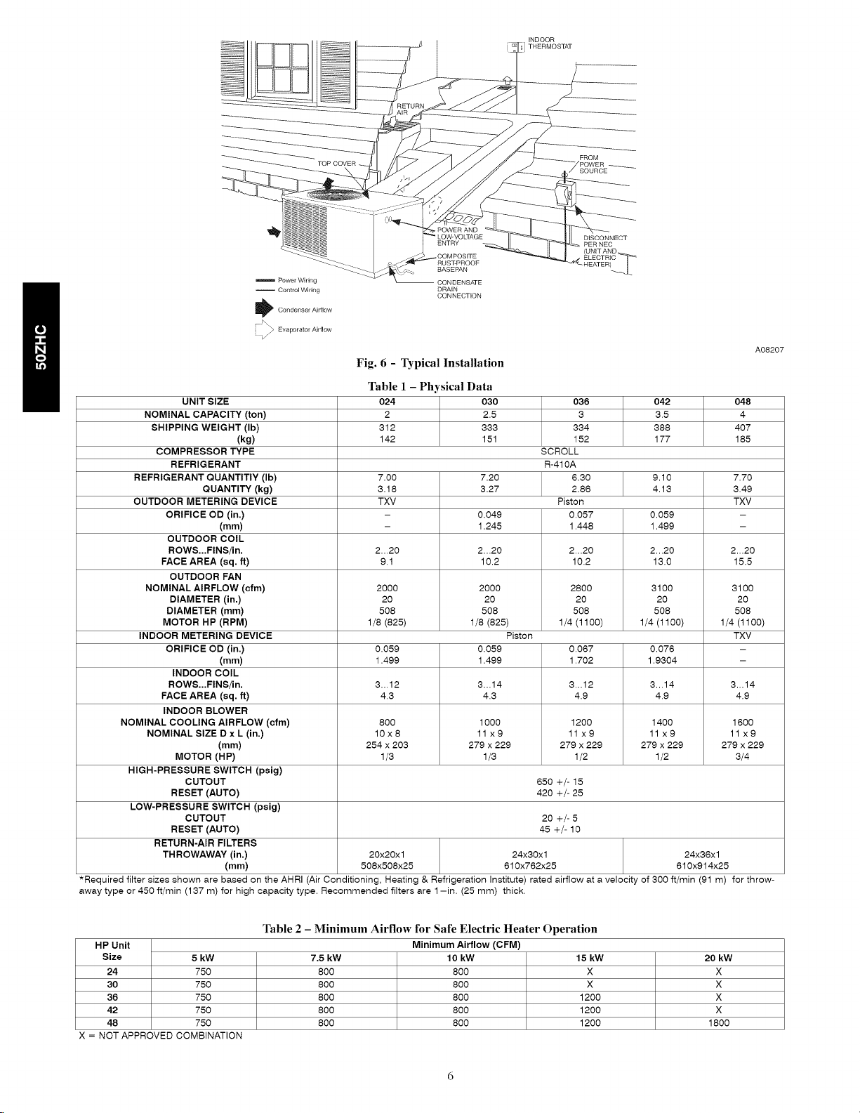
Power Wiring
-- Control Wiring
I_ Condenser Airflow
_ Evaporator Airflow
A08207
Fig. 6 - Typical Installation
UNIT SIZE 024 030 036 042 048
NOMINAL CAPACITY (ton) 2 2.5 3 3.5 4
SHIPPING WEIGHT (Ib) 312 333 334 388 407
(kg) 142 151 152 177 185
COMPRESSOR TYPE SCROLL
REFRIGERANT R-410A
REFRIGERANT QUANTITIY (Ib) 7.00 7.20 6.30 9.10 7.70
OUTDOOR METERING DEVICE TXV Piston TXV
QUANTITY (kg) 3.18 3.27 2.86 4.13 3.49
ORIFICE OD (in.) - 0.049 0.057 0.059 -
(mm) - 1.245 1.448 1.499 -
OUTDOOR COIL
ROWS...FINS/in. 2...20 2...20 2...20 2...20 2...20
FACE AREA (sq. ft) 9.1 10.2 10.2 13.0 15.5
OUTDOOR FAN
NOMINAL AIRFLOW (cfm) 2000 2000 2800 3100 3100
DIAMETER (in.) 20 20 20 20 20
DIAMETER (mm) 508 508 508 508 508
MOTOR HP (RPM) 1/8 (825) 1/8 (825) 1/4 (1100) 1/4 (1100) 1/4 (1100)
INDOOR METERING DEVICE Piston TXV
ORIFICE OD (in.) 0.059 0.059 0.067 0.076 -
INDOOR COIL
(mm) 1.499 1.499 1.702 1.9304 -
ROWS...FINS/in. 3...12 3...14 3...12 3...14 3...14
FACE AREA (sq. ft) 4.3 4.3 4.9 4.9 4.9
INDOOR BLOWER
NOMINAL COOLING AIRFLOW (cfm) 800 1000 1200 1400 1600
NOMINAL SIZE D x L (in.) 10x8 11 x9 11 x9 11 x9 11 x9
(mm) 254 x 203 279 x 229 279 x 229 279 x 229 279 x 229
MOTOR (HP) 1/3 1/3 1/2 1/2 3/4
HIGH-PRESSURE SWITCH (peig)
CUTOUT 650 +/- 15
RESET (AUTO) 420 +/- 25
LOW-PRESSURE SWITCH (peig)
CUTOUT 20 +/- 5
RESET (AUTO) 45 +/- 10
RETURN-AIR FILTERS
THROWAWAY (in.) 20x20x1 24x30x1 24x36x1
(mm) 508x508x25 610x762x25 610x914x25
*Required filter sizes shown are based on the AHRI (Air Conditioning, Heating & Refrigeration Institute) rated airflow at a velocity of 300 ft/min (91 m) for throw-
away type or 450 ft/min (137 m) for high capacity type. Recommended filters are 1-in. (25 mm) thick.
Table 1 - Physical Data
Table 2 - Minimum Airflow for Safe Electric Heater Operation
HP Unit Minimum Airflow (CFM)
Size 5 kW 7.5 kW 10 kW 15 kW 20 kW
24 750 800 800 X X
30 750 800 800 X X
36 750 800 800 1200 X
42 750 800 800 1200 X
48 750 800 800 1200 1800
X = NOT APPROVED COMBINATION
CONFIGURING UNITS FOR DOWNFLOW (VERTICAL)
DISCHARGE
Units are dedicated side supply products. They are not convertible
to vertical air supply. A field-supplied plenum must be used to
convert to vertical air discharge.
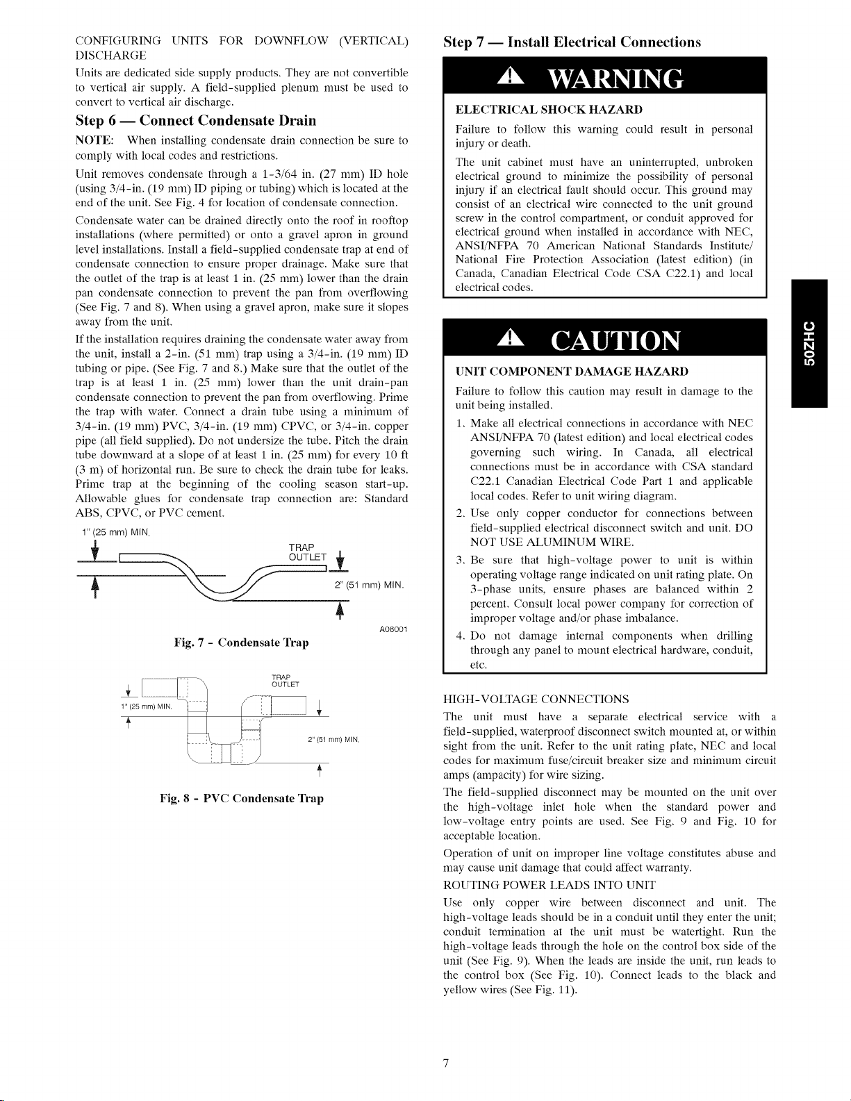
Step 6 -- Connect Condensate Drain
NOTE: When installing condensate drain connection be sure to
comply with local codes and restrictions.
Unit removes condensate through a 1-3/64 in. (27 mm) ID hole
(using 3/4-in. (19 mm) ID piping or tubing) which is located at the
end of the unit. See Fig. 4 for location of condensate connection.
Condensate water can be drained directly onto the roof in rooftop
installations (where permitted) or onto a gravel apron in ground
level installations. Install a field-supplied condensate trap at end of
condensate connection to ensure proper drainage. Make sure that
the outlet of the trap is at least 1 in. (25 mm) lower than the drain
pan condensate connection to prevent the pan from overflowing
(See Fig. 7 and 8). When using a gravel apron, make sure it slopes
away from the unit.
If the installation requires draining the condensate water away from
the unit, install a 2-in. (51 mm) trap using a 3/4-in. (19 mm) ID
tubing or pipe. (See Fig. 7 and 8.) Make sure that the outlet of the
trap is at least 1 in. (25 mm) lower than the unit drain-pan
condensate connection to prevent the pan from overflowing. Prime
the trap with water. Connect a drain tube using a minimum of
3/4-in. (19 mm) PVC, 3/4-in. (19 mm) CPVC, or 3/4-in. copper
pipe (all field supplied). Do not undersize the tube. Pitch the drain
tube downward at a slope of at least 1 in. (25 mm) for every 10 ft
(3 m) of horizontal run. Be sure to check the drain tube for leaks.
Prime trap at the beginning of the cooling season start-up.
Allowable glues for condensate trap connection are: Standard
ABS, CPVC, or PVC cement.
1"(25 mm) MIN.
TRAP
2" (51mm) MIN.
A08001
Fig. 7 - Condensate Trap
Step 7 -- Install Electrical Connections
ELECTRICALSHOCK HAZARD
Failure to follow this warning could result in personal
injury or death.
The unit cabinet must have an uninterrupted, unbroken
electrical ground to minimize the possibility of personal
injury if an electrical fault should occur. This ground may
consist of an electrical wire connected to the unit ground
screw in the control compartment, or conduit approved for
electrical ground when installed in accordance with NEC,
ANSI/NFPA 70 American National Standards Institute/
National Fire Protection Association (latest edition) (in
Canada, Canadian Electrical Code CSA C22.1) and local
electrical codes.
[]NIT COMPONENT DAMAGE HAZARD
Failure to follow this caution may result in damage to the
unit being installed.
1. Make all electrical connections in accordance with NEC
ANSI/NFPA 70 (latest edition) and local electrical codes
governing such wiring. In Canada, all electrical
connections must be in accordance with CSA standard
C22A Canadian Electrical Code Part 1 and applicable
local codes. Refer to unit wiring diagram.
2. Use only copper conductor for connections between
field-supplied electrical disconnect switch and unit. DO
NOT USE ALUMINUM WIRE.
3. Be sure that high-voltage power to unit is within
operating voltage range indicated on unit rating plate. On
3-phase units, ensure phases are balanced within 2
percent. Consult local power company for correction of
improper voltage and/or phase imbalance.
4. Do not damage internal components when drilling
through any panel to mount electrical hardware, conduit,
etc.
Fig. 8 - PVC Condensate Trap
2" (51 ram) MIN.
HIGH-VOLTAGE CONNECTIONS
The unit must have a separate electrical service with a
field-supplied, waterproof disconnect switch mounted at, or within
sight from the unit. Refer to the unit rating plate, NEC and local
codes for maximum fuse/circuit breaker size and minimum circuit
amps (ampacity) for wire sizing.
The field-supplied disconnect may be mounted on the unit over
the high-voltage inlet hole when the standard power and
low-voltage entry points are used. See Fig. 9 and Fig. 10 for
acceptable location.
Operation of unit on improper line voltage constitutes abuse and
may cause unit damage that could affect warranty.
ROUTING POWER LEADS INTO UNIT
Use only copper wire between disconnect and unit. The
high-voltage leads should be in a conduit until they enter the unit;
conduit termination at the unit must be watertight. Run the
high-voltage leads through the hole on the control box side of the
unit (See Fig. 9). When the leads are inside the unit, run leads to
the control box (See Fig. 10). Connect leads to the black and
yellow wires (See Fig. 11).
 Loading...