

Page 1
Jrt<twnna y >' ^
Numb^One
AirConditbning
Maker
installation, Start-llp
Division of
Carrier Cotporalio
e
Carrier Parkway • Syracuse NY 13221
Single-Package Heat Pumps
and Service instructior^
SAFETY CONSIDERATIONS
INSTALLATION
Step 1 — Check Equipment and Jobsite
• UNPACKAGE UNITS
• INSPECT EQUIPMENT
• COMPLETE OR CONSIDER SYSTEM
REQUIREMENTS
Step 2 — Mount Heat Pump Package ..
• ON THE GROUND: MOUNT HEAT
PUMP ON AN ELEVATED FRAME
POSITIONED ON A LEVEL CON
CRETE PAD
• ON THE ROOF: MOUNT UNIT ON A
LEVEL PLATFORM OR FRAME
Step 3 — Make Ductwork Connections
• CONNECT SUPPLY AND RETURN
AIR DUCTWORK
.................................................
.........................
Page
1
, 1-4
. 1
INDEX
Step 4 — Provide for Cooling Cycle
Condensate Disposal for Cooling Cycle ... 4
• CONNECT DRAIN LINE
^Step 5 — Make Electrical Connections... 4
• INSTALL A BRANCH CIRCUIT
DISCONNECT PER NEC
• ROUTE LINE POWER WIRES INTO
UNIT
• CONNECT GROUND LEAD TO GROUND
LUG IN SPLICE BOX FOR SAFETY
• SET INDOOR FAN MOTOR SPEED
• ROUTE CONTROL POWER WIRES
• ELECTRIC HEATER INSTALLATION
START-UP.............................................................5-7
SERVICE .............................................................7-14
V TROUBLESHOOTING
..................................
15, 16
^ SAFETY CONSIDERATIONS
Installation and servicing of air conditioning
equipment can be hazardous due to system pressure
and electrical components. Only trained and quali
fied service personnel should install, repair or
service air conditioning equipment.
Untrained personnel can perform basic main
tenance functions of cleaning coils and filters and
replacing filters. All other operations should be per
formed by trained service personnel. When working
on air conditioning equipment, observe precautions
in the literature, tags and labels attached to the unit
and other safety precautions that may apply.
Follow all safety codes. Wear safety glasses and
work gloves. Use quenching cloth for brazing oper
ations. Have fire extinguisher available for all braz
ing operations.
INSTALLATION
Step 1 — Check Equipment and Jobsite
UNPACKAGE UNITS — Move units to final loca
tion. Slide units from cartons taking special care nob
to damage unit.
INSPECT EQUIPMENT — File claim with ship
ping company if shipment is damaged or incomplete.
COMPLETE OR CONSIDER SYSTEM RE
QUIREMENTS before installing the 50YQ units.
Consult local building codes and National Elec
trical Code (NEC) for special installation
requirements.
Provide sufficient space for coil airflow clearance,
wiring, and servicing unit. (See Fig. 1.) Locate unit
where supply and return air ducts can be con
veniently brought out to unit duct connections.
Unit may be placed with duct side as close to
building as condensate drain, top removal, duct con
nections and power connections permit. Position
unit so water or ice from roof does not drop directly
on top of unit or in front of coil. Make provisions for
condensate drainage and defrost water disposal.
Roof installation method for 50YQ depends on
building construction and special requirements of
local building codes. Ensure that roof can support
unit weight. Protect unit from prevailing winds to
ensure adequate defrost.
© Carrier Corporation 1979 781 Form 50YQ-3SI
Page 2

0'-6j3^
■g CONDUIT
CONTROL-*“»
WIRING
If DKO
ELECTRIC^
HEAT X
l| DKO
LINE
WIRING'
CONN
L> INDOOR AIRFLOW
^ OUTDOOR AIRFLOW RIGHT SIDE VIEW
Ceitified dimension drawings available on request
Fig. 1
Dimensions and Connections
Table 1 — Installation Data (See Fig. 1)
UNIT
OPER WEIGHT (lb)
dTmeNsToNS (ft-in )
A
B
C' 1-11-5/8 1-11-5/8 1-11-5/8
DUCT CONN (ft-in )
D 1- 7-3/4 1- 7-3/4
FILTER SIZEt (in.)
Disposable 20x25
Permanent 15x20
‘Dimension "C" includes 1-in built-in base support channels
fRecommended field-supplied filters are 1-in thick
50YQ024
303
50YQ030
320
15x20 (2)
20x20 20x25 20x25
Step 2 — Mount Heat Pump Package
ON THE GROUND; MOUNT HEAT PUMP ON
AN ELEVATED FRAME POSITIONED ON A
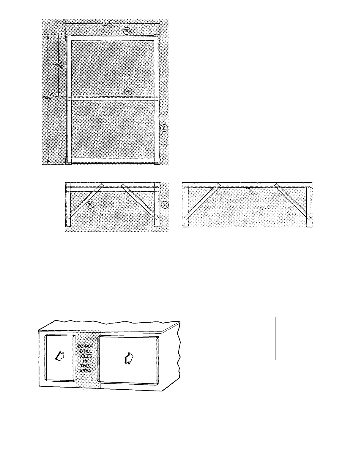
LEVEL CONCRETE PAD See Pig. 2 for pad
dimensions. Ensure pad does not obstruct coil slots
in unit basepan. (Slots drain water during heating
and defrost cycles. See Fig. 2 for drain slot loca
tions.) Construct pad a minimum of 6 in. thick to
provide clearance under basepan coil slots for
drainage and ice buildup. In areas where prolonged
subfreezing temperatures or snowfall occur,
increase clearance to 12 to 18 inches by constructing
an angle-iron frame to support unit 12 to 18 in. off
concrete base. Design cross angle of frame so as to
not obstruct basepan coil slots. See Fig. 3 for recom
mended frame construction. Alternate construction
should follow dimensions. Extend a 24-in. gravel
apron around pad for condensate and defrost water
drainage field.
ON THE ROOF: MOUNT UNIT ON A LEVEL
PLATFORM OR FRAME — Elevate unit for
proper clearance as described under ground installa
tion above. Design roof and plan water runoff so as
to prevent unit and its duct flashing from sitting in
water, in accordance with all applicable codes.
50YQ036
333
4-0-7/16
3-6-1/4
Side-by-Side Rectangular
1- 7-3/4 1 1-11-3/4
15x20
20x20
50YQ042
375
2- 3-5/8
20x20 (2)
50YQ048
417
2-7-5Z8
2-3-3/4
20x25
20x20
15x20 (2)
50YQ060
448
3-1-5/8
2-9-3/4
25x25
_2.Ûx25 ^
20x20 (2)
Step 3 — Make Ductwork Connections
CONNECT RETURN AND SUPPLY AIR
DUCTWORK — Connect ductwork to unit supply
and return air duct connections. Refer to Fig. 1 and
Table 1 for unit supply and return air connection
sizes and locations.
NtWfTSaX:OFU1«T
«ïTH «JCT coitwecTfONS.
«Nfraasc
?ïEAfîsii«e8?a«(T^
i
y-t ■
A / ■
UNIT OUTÏ-iN?-
•JEF^SSBE
WT» Access &msjs
ooKOT i««oei%E»soss«E«T>
mnotutcPimz ^
d47«IS AilES.
mres.
t to 3f«as «lowiait <w ssibir«i!iife9 «ievSKNf
fr««» as(Xi, <S«!«>s.on A «• 4S >o, <s 3S sncsse«^ 1«
3r«AS where eievsieci f:e«» is f.oi A w A2
iHmee&'cm B js 3T xiches
2 AJiow a 3'*t service, ctoarahce at frotrt fear anc feit sioe of unit
Fig. 2 — Concrete Pad Dimensions
fMm
Page 3
iz TOS'«
0C
□ «Sy iSJRSS
<D’=
O'i-
!_
Ajrets íftOfí - li TO f-s COMMt STO { ■POTAL í&6ftMTrTY 2Sf 7035Ÿ >
m.0 FRA«E TO^TtíE».
PAífíT WlTH2l«C-ÍÍ}C» ?*»ÍT(StíSTf«OOP>
re“ fc&5 fíBi
3 3}í(J}fiS£0
F¡g. 3 — Heat Pump Mounting Frame
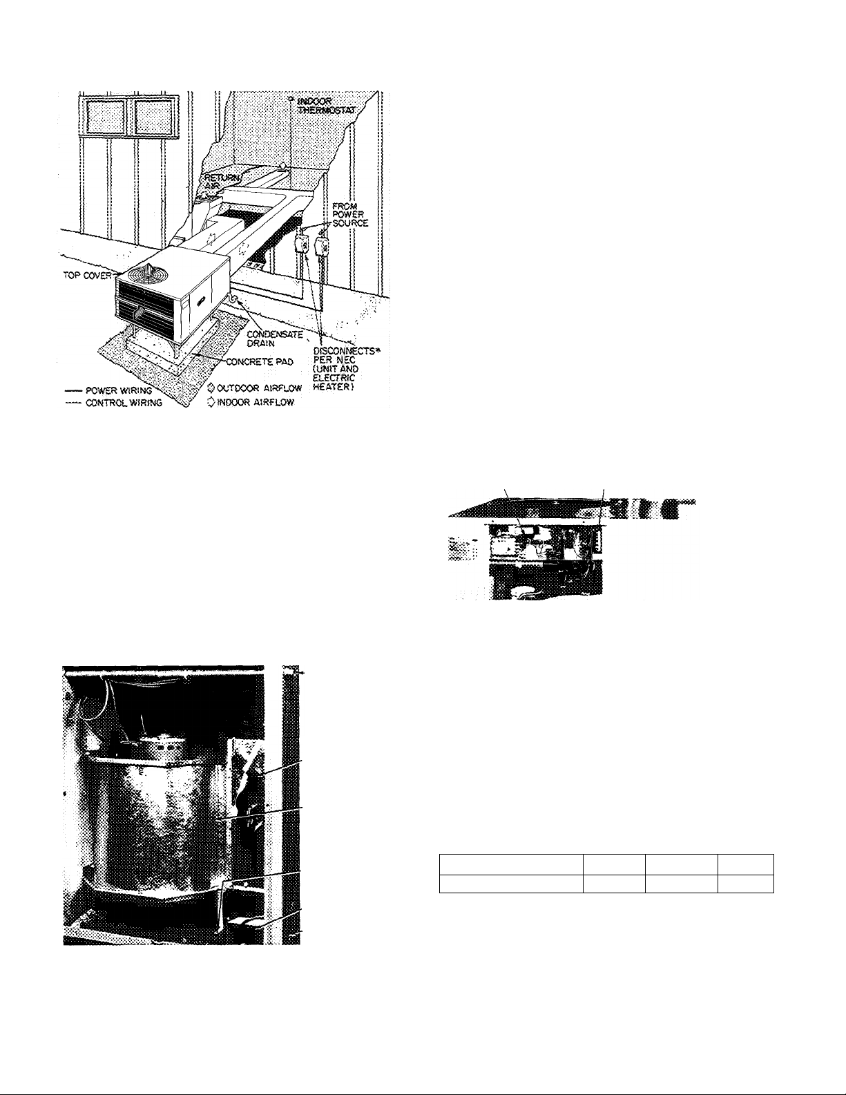
Flanges are provided on unit for rectangular duct
connections. Figure 4 shows a typical duct system
with 50YQ installed. Do not operate unit longer
than 5 minutes without ductwork. If necessary, refer
to Carrier System Design Manual, Part 2, for sys
tem air duct design. When designing and installing
ductwork, consider the following:
a. When connecting ductwork to unit, do not drill
holes in area shown below. Coil may be damaged.
b. Install field-supplied filters in return air duct
work. Recommended sizes for filters are shown
in Table I.
c. Avoid abrupt duct size increases and reductions.
■d. Use flexible connectors between ductwork and
unit to prevent transmission of vibration. When
electric heater is installed, use fireproof canvas
(or similar heat resistant material) connector be
tween ductwork and unit discharge connection.
If flexible duct is used, insert a sheetmetal sleeve
inside duct. Design this connector or sleeve so
that it extends 24 in. from electric heater element.
Size ductwork for cooling air quantity (cfm). The
e.
minimum air quantity for proper heating/ cooling
operation and electric heater operation is 400 cfm
per ARI cooling ton as listed below:
UNIT 50YQ MIN CFM
024 833
030
036
042
048
060 193 3
100 0
118 3
136 6
163 3
Heater limit switches may trip at air quantities
below those recommended.
Insulate and make weatherproof all external
ductwork. Insulate and cover with a vapor
barrier all ductwork passing thru unconditioned
spaces. Follow latest SMACNA (Sheet Metal
and Air Conditioning Contractors National
Association) and NESCA (National Environ
mental Systems Contractors Association) mini
mum installation standards for residential heat
ing and air conditioning systems.
Page 4
g. Secure all ducts to building structure. Weather
proof duct openings in wall or roof according to
good construction practices.
"Separate disconnect required for electric heater
> Fig. 4 — Typical Installation — 50YQ
Step 4 — Provide for Cooling Cycle Conden
sate Disposal — Condensate may be drained
directly onto gravel apron or connected by drain
line(s) to a dry well. Follow local codes.
CONNECT DRAIN LINE to rubber condensate
drain fitting on side of unit (see Fig. 5). Use clamp
provided. Install factory-supplied condensate trap
(taped to indoor fan compartment for shipment) at
end of drain line. If a drain line is not used, connect
condensate trap to unit drain fitting as shown in
Fig. 5.
CONDENSATE
TRAP (SHIPPING
LOCATION, INSTALL
ON CONDENSATE
DRAIN LINE)
voltage to unit is within ± 10% of voltage indicated
on nameplate. On 3-phase units, check that phases
are balanced within 2%. Contact local power
company for correction of improper line voltage.
Oisrratton «kf tïiïÿi <M3t 3t
wth exijessm phase
¡as
coiaM
affect waCFaïïty,
See Table 2 for recommended wire and fuse
sizes.
INSTALL A BRANCH CIRCUIT DISCONNECT
PER NEC of adequate size to handle unit starting
current. Provide a separate disconnect for unit
and for each accessory electric heater circuit as
required. (See electrie heater Installation, Start-Up
and Service Instructions.) Locate disconnect(s)
within sight of and readily accessible from the unit,
per Section 440-14 of National Electrical Code
(NEC).
ROUTE LINE POWER LEADS INTO UNIT ^
Extend leads from disconnect per NEC thru hole
provided (Fig. 1) into line wiring splice box (Fig. 6).
Use copper or copper-clad aluminum wire. (Do not
make connections with aluminum wire.)
UNIT
CONTROL BOX
CONTROL WIRING
TERMINAL BOX
Fig. 6 — Unit Control Box
CONTROL WIRING
CONDUIT,
CONNECT GROUND LEAD TO GROUND
LUG IN SPLICE BOX FOR SAFETY — Connect
power wiring. See Fig. 7. Connect line power leads
to yellow and black pigtails on single-phase units;
yellow, blue and black pigtails on 3-phase units.
SET INDOOR FAN MOTOR SPEED — Refer to
page 3 for minimum allowable air quantity for safe
electric heater operation. Three-speed indoor fan
motor is factory wired for high-speed operation.
Fan motor is equipped with spade-type speed selec
tor terminals marked 1, 2 and 3. For electric heater
operation, set motor at: “Low” — sizes 024 thru 042;
“High” — size 048; “Med” — size 060.
CONDENSATE
DRAIN LINE
¡i DKO LINE
POWER
Fig. 5 — Condensate Drain and Trap Details
Step 5 — Make Electrical Connections — In
stall field wiring in compliance with local and
national fire, safety and electrical codes. Be sure
781
MOTOR TERMINAL
FAN SPEED
1
High Medium Low
2 3
ROUTE CONTROL POWER WIRES (24-v) thru
7/8-in. conduit provided in unit. Fig. 1 and 5. Ex
tend leads to unit control wiring terminal board in
unit control box. Connect leads to terminal board
as directed in Fig. 8.
The 50YQ unit transformer supplies 24-v power
for complete system including accessory electric
heater.
Page 5
i-r'
tv
Table 2 — Unit Electrical Data (60-Hz)
OPER
VOLTAGE*
MODEL
50YQ024
50YQ030
^ 50YQ036
50YQ042
50YQ048
50YQ060
50YQ042
50YQ048
50YQ036
50YQ042
50YQ048 70
50YQ042
50YQ048 35
50YQ042
50YQ048 30 60
AWG
BCSC
FLA
IFM
LRA
OFM
RLA
HACR — Heating Air Conditioning & Refrigeration
V/PH
Max Min
207
230/1
208/230/1 253
200/3 220
200/230/3 253
230/3
460/3 506
575/3 632 518
American Wire Gage
Branch Circuit Selection Current
Full Load Amps
Indoor Fan Motor
Locked Rotor Amps
Outdoor Fan Motor
Rated Load Amps
253
253
187tt
180
180
207
414
COMPRESSOR
LRA
66
72
88
94 21.0
106
150
79 146
87 16 9 183 49
87
gT~
35
27
RLA
154
16 1
18 2
25 0 27 9 49
29 2/33 4
12 5/11 7
U6 143
14 8 16 4 4 9 2 2 10 58
g 3
7.5 8 8
49
BCSC
ELECTRIC HEATER INSTALLATION — For
complete heater installation data, refer to accessory
electric heater Installation, Start-Up and Service
Instructions.
GROUND LUG
(IN SPLICE BOX)
--GROUND LEAD-
l-PHASE
CONN
TO
DISCONNECT
PER NEC
3-PHASE
CONN
TO
DISCONNECT
PER NEC
_____
Field Wiring Splice Connections
NOTE Use copper or copper-clad aluminum wire
________________
Ll
________________
L2
------
GROUND LEAD-
LI----------------------------------------------
L2-
______________________________
L3
BLK
-YEL
50YQ HEAT PUMP
GROUND LUG
(IN SPLICE BOX)
■ -^-BLK--
BLU
-YPl
------------------------
-YEL
50YQ HEAT PUMP
-----------
----------
-----------
------------
(
i
i
i
Fig. 7 — Line Power Connections
START-UP
The 50YQ unit compressors are equipped with
crankcase heaters. It is recommended that heater be
energized a minimum of 24 hours before starting unit.
To energize heater only, set thermostat at OFF posi
tion; turn on unit main power at disconnect switch.
IFM
OFM
Min
FLA FLA
—
2 4 1 3 10 48
—
24 1 3 10
—
21 2
35 3
16 6 49 20 10
— 3 6
6 8
64 49 2 2
^Permissible limits of the voltage range at which units will operate
satisfactorily
tCopper wire sizes based on 60 C Use copper or copper-clad aluminum wire
only Use latest NEC for copper-clad aluminum conductor sizing
^Required when using nonmetallic conduit
“Maximum dual element fuse
ttMinimum voltage is 197 when outdoor ambient temperature exceeds
105 F
2 1 10 38 10 45
3 6
1 9 8
49
2 2
6 4 20
2 2
2 1 10 74
49”
i¥~ 67
1 9 ‘
49
4 9 2 2 14 90
49 1 9
Wire
Size
(AWG)t
6
4
10
14
14 164 14
14 141 14 15
BRANCH CIRCUIT
Min Gnd
Max
Ft
Wire
(AWG)t
}— -1
46
52 10 50
71 10
43
55 10 40
48
104 14 15
Max Fuse
Wire
or HACR
Type Ckt»*
Size
Bkr Amps
10
6
10 45 30 0
10 30 21.3/25 3
id 24 7
10 40 27 6
12 20
Min
Circuit
Amps
35 23 0
35
60
60
15 11 2
23 8
28 5
33 3
42 0
52 5
27 6
12 4
14 6
10 9
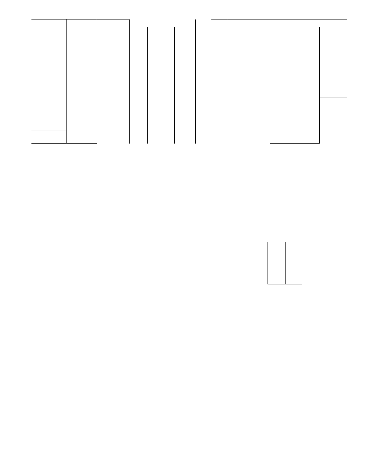
Heat Anticipator Settings for Room Thermo
stat — Set anticipator settings for room thermostat
according to Table 3. These settings may be changed
slightly to provide a greater degree of comfort for a
particular installation.
Table 3 — Thermostat Anticipator Setting
ACCESS.
ELECTRIC
HTR (Kw)
240 V 280 V
5 0 3 75
5 6
7 5
7 5
100
15 0 11 3
20 0 150
25 0 188
27 0
22 25
SECOND STAGE
ANTICIPATOR
SETTING
-gg— —
26
26
52
52
52
78
UNIT
50YQ024,
030,036,
042,048,
060
FIRST STAGE
ANTICIPATOR
SETTING
Fixed
Accessory Outdoor Thermostat provides adjust
able outdoor control of accessory electric heaters
of 15 Kw and over. This thermostat makes contact
when a drop in outdoor temperature occurs. It ener
gizes a stage of electric heat when the outdoor tem
perature setting is reached, provided the room
thermostat is on the second stage of heating. One
outdoor thermostat is recommended for each stage
of electric heat after the first stage. Set the outdoor
thermostat(s) progressively lower for each stage.
Refer to heat load of building and unit capacity to
determine the correct outdoor thermostat settings.
The accessory emergency heat relay is required
when 2 outdoor thermostats are used. It is auto
matically energized by the manually operated emer
gency heat switch in the indoor thermostat subhase.
The indoor thermostat locks out compressor and the
relay bypasses the outdoor thermostats for electric
heater operation during heat pump shutdown.
When one outdoor thermostat is used, an emergency
heat relay is not required. The emergency heat
switch in the indoor thermostat subbase bypasses
outdoor thermostat, locks out compressor and acti
vates electric heater.
184
Page 6

MOUNT OUTDOOR THERMOSTAT(S) —
Locate maximum of 2 outdoor thermostats in the
compressor section on the partition to the left of the
reversing valve. Fasten with sheet metal screws using
engagement holes provided. Uncoil a short length of
capillary and insert bulb into rubber grommet in the
partition. Moisten bulb to assist insertion. Insert all
but 1 in. of bulb. Secure remaining capillary.
MOUNT EMERGENCY HEAT REEAY in the
compressor section on the partition to the left of the
reversing valve using engagement hole provided.
Fasten with sheet metal screws.
To Start Unit — Check that main power is on and
that compressor crankcase heater has been ener
gized for at least 24 hours.
1. Check that heater main power is on as applicable.
2. Set selector switch at OFF.
3. Set fan switch as desired (FAN) (AUTO.).
4. Set thermostat dial at the desired temperature.
5. Set selector switch at HEAT or COOL. Check
system refrigerant charge. See Refrigerant
Charging.
Unit Single-Phase Compressors that are
Equipped with a Compressor Start Thermistor
(PTC device) (024,030,036) — When supply
voltage is within 10% limit and compressor does not
start, check the start thermistor with an ohmmeter.
CHECKING START THERMISTOR
1. Shut off all power to unit and wait 10 minutes
for thermistor to cool to ambient temperature.
2. Remove thermistor from circuit.
3. Measure resistance of thermistor with ohmmeter. Normal resistance readings are 25 ohms
± 20% at 75 F ambient temperature.
4. If ohmmeter resistance reading is not within the
± 20%, the thermistor is defective and must be
replaced.
THERMOSTAT
a SUBBASE
(SEE BELOW)
CHANGEOVER
Automatic
Manual
Manual
Automatic
___
SUBBASE
J-IH93AZ073
HH93AZ075
Subbase included
Subbase included
50YQ UNIT
CONTROL WIRING
TERMINAL BOX
THERMOSTAT
HH07AT071
HH07PZ085
HH07PZ08^6
COOLING AND ONE-STAGE HEATING
(without Electric Heater)
THERMOSTAT
a SUBBASE
(SEE BELOW)
R -
G —
—
Y -
0 --
E —
L
HR — Heater Relay
INSTALL r'
JUMPER
50Y0 UNIT
CONTROL WIRING
TERMINAL BOX
-- R
- G
- Y
0
-W3 —
-VI0-(HRI
-0RN-(HR3
-BRN
COOLING AND TWO-STAGE HEATING
(Unit equipped with 88EJ Electric Heater,
Emergency Heat, no Outdoor Thermostats)
Fig. 8 — Control Connections
THERMOSTAT
a SUBBASE
(SEE BELOW)
R -
G -
Y -
0 -
W2-
E -
INSTALLJUMPER
CONTROL WIRING
TERMINAL BOX
ro^—
! =^00
50YQ UNIT
- R
• G
--------
Y
- 0
-E-
- -W3-
C -
-VI0-(HR1
--------
^BLK-(hR2)
-0RN-(hR3
-BRN
ODT — Outdoor Thermostat
HR — Heater Relay
COOLING AND TWO-STAGE HEATING
(Unit equipped with 88EJ Electric Heater,
Emergency Heat, one Outdoor Thermostat)
THERMOSTAT
a SUBBASE
(SEE BELOW)
R - -- R
G - - G
Y -
0 -
W2--
(EH^ j0DT2[^"U0DTl
E --
1 L -|
c —
L
— Emergency Heat Relay
EHR
— Heater Relay
HR
— Outdoor Thermostat
ODT
50YQ UNIT
CONTROL WIRING
TERMINAL BOX
— Y
-- 0
-^W2^:
■ - E —^
-W3—^
— C — -
-VI0-(HRI
I"LI
Lehr"
J
-■bRN-(HR3'
COOLING AND TWO-STAGE HEATING
(Unit equipped with 88EJ Electric Heater, Emergency
Heat Relay, two Outdoor Thermostats)
781
Page 7

If start thermistor is good and compressor does
not start, disconnect the thermistor from starting
circuit and give compressor a temporary capaci
tance boost as described below. Run compressor for
10 minutes, then shut off and allow system pressure
to equalize. Reconnect start thermistor and try
restarting compressor without boost capacitor. If
after 2 attempts the compressor does not start, re
move thermistor and add an accessory start capaci
tor relay package.
Single-Phase Units 50YQ024,030,036 and
042 — When supply voltage is within 10% limit
and compressor does not start, give compressor a
temporary capacitance boost.
^TEMPORARY CAPACITANCE BOOST — If
necessary, see Carrier Standard Service Techniques
Manual, Chapter 2, Electrical, for details.
WARKSNG; Cajjaciiaace boost Ls to be perfotaacfd írasaeá porsoKoeL improper proce-
tlare cottjá «sose injxtry.
SERVICE
High-Pressure Relief Valve (Safety Control) is
located in compressor. Relief valve opens at a
pressure differential of approximately 550 psi
between suction (low side) and discharge (high side)
to allow pressure equalization.
Internal Current and Temperature Sensitive
Overload (Safety Control) resets automatically
when internal compressor motor temperature drops
to a safe level (overloads may require up to 1 hour to
reset). When an internal overload is suspected of
being open, check by using an ohmmeter or con
tinuity tester. If necessary, refer to Carrier Standard
Service Techniques Manual, Chapter 2, Electrical,
for complete instructions.
Defrost Control, consisting of a defrost timer,
defrost thermostat and defrost relay, interrupts
normal system heating operation to remove frost
and ice formation on outdoor coil. Frost impairs
unit performance. Defrost control simultaneously
stops outdoor fan, energizes reversing valve sole
noid to switch system into cooling cycle (outdoor
unit as condenser, indoor unit as evaporator), and
activates accessory electric heater. Unit can defrost
every 90 minutes, but will do so only if outdoor tem
peratures are in the frosting temperature zone.
For heat pump to defrost, 2 conditions are
necessary:
1. Defrost timer contacts must be closed.
2. Refrigerant temperature must be cold enough to
cause defrost thermostat contacts to close. Con
tacts close at 27 ± 3F.
Every 90 minutes of elapsed running time, the de
frost timer contacts close for 10 seconds. If the
defrost thermostat contacts are closed, the unit de
frosts. The defrost timer limits defrosting period to
10 minutes. Normally the frost is removed and the
defrost thermostat contacts will open to terminate
defrosting before 10 minutes have elapsed. Defrost
thermostat contacts open at 80 ( ± 6)F. When de
frosting is terminated, the outdoor fan motor is
energized and reversing valve solenoid is de
energized, returning unit to heating cycle.
HEAT PUMP CIRCUITS shown in Fig. 9 are
refrigerant flow diagrams for heating and cooling
cycles.
> Refrigerant Charging
CAUTION: To mcvem personal injttxy, wear
safety glasses and gloves when handHng
refrigerasL
Do not overcharge systemv An overcharge
can cause compressor flooding.
7Q I
Page 8

Table 4 — Service Data
UNIT 50YQ
R-22 CHARGE* (lb)
Refrig Control
INDOOR FAN
Rpm
Diameter (in.) 9 9
Width (in.)
Range (cfm)
Motor Hp
OUTDOOR FAN
Cfm 2500
Rpm
Diameter (in.) 20 20
Motor Hp 1/5
"Factory refrigerant charge
024
54 5 7 5 15
7 7
833-1040 1000-1250
1/5 1/5
1050
030 036
2500 2500
1050 1050
1/5 1/4
Unit refrigerant system is factory charged. When
recharging is necessary, weigh in total charge indi
cated in Table 4. (Charge must be weighed in during
heating season.) Remove any refrigerant remaining
in system before recharging. If system has lost com
plete charge, evacuate system to 500 microns
(29.7 in. vacuum) before recharging. Service port
connections are provided on unit suction and dis
charge lines for evacuation and charging. (See
Fig. 10 for service port location.) Dial-a-charge
charging cylinder is an accurate device used to re
charge systems by weight. These eylinders are avail
able at refrigeration supply firms.
042
AccuRater^M
Centrifugal — Direct Drive — 3-Speed
1100/1050/900
9
9
1183-1480
1/3
Propeller — Direct Drive
20
6 7
10
9
1367-1708
1/2
2700
1050
20
1/4
048
7 3
10
9
1633-2040
1/2
3200 3600
1050
20
1/4
1800-2250
To check system operation during heating cycle,
use correct Heating Cycle Operation Check Chart
(Fig. 17 thru 22). These charts indicate whether a
correct relationship exists between system operating
pressures and air temperatures entering unit. If
pressure and temperature lines do not intersect on
chart, the system refrigerant charge may not be cor
rect or other sysem abnormalities may exist. Do not
use Operation Check Charts to adjust refrigerant
charge. Weigh charge into system.
COOLING CYCLE CHARGING CHART
METHOD
060
8 6
10
10
3/4
1050
20
1/4
OUTDOOR FAN
DISCHARGE GRILL
TOP COVER
UNIT CONTROL
BOX
REVERSING
VALVE \
SUCTION LINE'
SCHRADER
FITTING
COMPRESSOR
HOLD DOWN
BOLTS
CONTROL WIRING
TERMINAL BLOCK
ELECTRIC
COMPRESSOR aIsEMBLY
INDOOR INDOOR BLOWER
COIL MOTOR I
CONTROL WIRING
CONDUIT
CONDENSATE \
DRAIN LINE LINEWIRING
SPLICE BOX
Fig. 10 — Component Location (Typical)
To check and/or adjust charge during cooling
season, use correct Cooling Cycle Charging Chart
(Fig. 11 thru 16) and follow Charging Chart Method
below. The charging chart may also be used as an
alternate method of recharging system.
1. Operate unit a minimum of 10 minutes before
checking charge, and after each charge
adjustment.
2. Measure suction pressure by attaching a gage to
unit suction service port. (See Fig. 10 for correct
service port location.)
3. Measure outdoor (coil inlet) air dry-bulb tem
perature. Use service thermometer.
4. Using a sling psychrometer, measure wet-bulb
temperature of air entering indoor fan coil.
5. Refer to correct Charging Chart. Locate on
curves where outdoor air dry-bulb and indoor
air wet-bulb temperature lines intersect.
6. From intersect point, project vertically down
ward to chart suction pressure line. Compare
chart suction pressure to unit suction pressure
(Step 2).
7. If unit suction pressure is lower than ehart
pressure, add refrigerant to system until chart
pressure is reached. If unit suction pressure is
higher than chart pressure, remove refrigerant
until chart pressure is reached.
781
Page 9

SUCTION PRESSURE <§) SCHRADER VALVE (PSIG)
Fig. 11 — Cooling Charging Chart —
50YQ024
Fig. 13 — Cooling Charging Chart —
50YQ036
Fig. 12 — Cooling Charging Chart —
50YQ030
Fig. 14 — Cooling Charging Chart
50YQ042
Page 10

Fig. 15 — Cooling Charging Chart —
50YQ048
Fig. 17 — Heating Operation Check Chart —
50YQ024
40
50 60 70 80 90
SUCTION PRESSURE @ SCHRADER VALVE (PSIG)
Fig. 16 — Cooling Charging Chart
50YQ060
Fig. 18 — Heating Operation Check Chart —
50YQ030
i
10
Page 11

10 20 30 40 50 60 70
SUCTION PRESSURE @ SCHRADER VALVE (PSIG)
Fig. 19 — Heating Operation Check Chart
50YQ036
Fig. 21 — Heating Operation Check Chart
50YQ048
Fig. 20 — Heating Operation Check Chart
50YQ042
10 20 30 40 50 60 70 80
SUCTION PRESSURE @ SCHRADER VALVE (PSI8)
Fig. 22 — Heating Operation Check Chart —
50YQ060
Page 12

AccuRater™ (Dual-Piston Type) Servicing —
See Fig. 23 for dual-piston AccuRater components.
The pistons have a refrigerant metering orifice thru
them. The retainers form a stop for the pistons in the
refrigerant bypass mode, and a sealing surface for
liquid line flare connection. To check, clean or
replace piston;
1. Shut off power to unit.
2. Remove refrigerant from unit.
3. Remove liquid line flare connections from
AccuRater.
4. Note position of arrow on AccuRater body with
respect to unit.
5. Pull retainer out of body. Be careful not to
scratch flare sealing surface. If retainer does not
pull out easily, carefully use vise grips to remove
retainer. Replace scratched or damaged retainer.
6. Slide piston out by inserting a small soft wire thru
metering hole (18-gage thermostat wire). See that
metering hole, sealing surface around piston
cones and fluted portion of piston are not
damaged.
7. Chart on unit access panel illustrates proper
arrangement and sizes of pistons.
8. Clean piston refrigerant metering orifice.
9. Replace container O-ring before reassembling
AccuRater. Carrier O-ring part no. is
99CC501052.
LIQUID LINE STRAINERS (protect Accu
Rater), are made of wire mesh and located in the
liquid line on each side of the AccuRater. The
strainers are pressed into the line. Remove strainer
by threading a #10 sheet metal screw into strainer
and pulling the screw with pliers.
Compressor Removal — See Table 5 for com
pressor information and Fig. 10 for component
location. Follow safety codes, and wear safety
glasses and work gloves. Have quenching cloth
available (step 8).
CAUTION: ttibijag leased ki 50 ¥Q
ccals. po xiot «yediest place excessive
Stiais iabxag or dasjage may result.
Table 5 — Compressor Data
MODEL
50YQ024 M24
50YQ030
50Y0036
50YQ042
50Ya048
50YQ060
Refer to compressor nameplate for complete model number
PRODUCTION
COMPRESSOR*
M27
M34
P46
P53
P64 76
OIL RECHARGE (oz)
44
44
44
76
76
1. Shut off power to unit. Remove unit access
panel. Fig. 10.
2. Remove refrigerant from unit using refrigerant
removal methods described in Carrier Standard
Service Techniques Manual, Chapter 1,
Refrigerants.
3. Remove core from suction and discharge line
Schrader valves.
4. Disconnect compressor wiring at compressor
terminal box.
5. Using a tubing cutter, cut suction and discharge
lines at convenient place near compressor for
easy reassembly to new compressor with copper
clip couplings.
CAUTION: Excessive tiiovemesit of copper
Jities at compressor may cso&e a break where
Imes connect to other system componcius.
6. Remove crankcase heater from compressor
base.
7. Remove compressor hold-down bolts and lift
compressor out.
8. Carefully unbraze suction and discharge line
piping stubs from compressor. If oil vapor in
piping stubs ignites, use quenching cloth.
CAUTION: MoSkr may copiainquantity of
Braze piping stubs (removed in step 8) on new
9.
compressor.
Install new compressor in unit. Braze suction
10.
and discharge lines to compressor piping stubs
(at points where cut, step 5) using field-supplied
copper couplings. Ensure compressor hold
down bolts are in place. Connect wiring.
COOU^NS
PiSTON
fLARS
NUT
S,TBA!Ï£B -,
RETAiiÆR
\ ^
COOLfNS
TO:
COTOOOR
cote
NOTE P«ton sizes are tabuteîed on unit access par.ef. Saainefs are îocateci >n iKjciti tine on eecti side ot AccuRater
Relative poS't'on of coccpor^er.ts is critical for ccrect operet.or.
RUeSERO-RlNG
Fig. 23 — AccuRater^^ (Dual-Piston) Components
Plow
COOUfiS PiSTON
STAii«PEDAf?i?OWOK
CCOPUING SOOr
(TCWAROiNDOOR COfU
12
HEATiwe
PLOW
PJSTO«
RUЭДeЯO'Rl^4й
STRAiNER
RETAINER
TO
■«DOOR
PCARE
NUT
Page 13

11. Clean system. Add new suction line filter-drier
as described below.
NOTE: If a compressor failure was caused by
motor winding burnout, the by-products of the
burnout must be separated from the circulating
refrigerant. This must be done before the by
products enter the reversing valve or accumu
lator and render parts inoperative. Burnout by
products can cause future system operating
problems if left in the system.
Clean the system by installing a suction line
drier in the refrigerant line where the suction gas
enters the reversing valve. During the cooling
cycle, this is the line from the indoor coil run
ning across the top of compressor compart
ment; during heating cycle, install drier in line
between outdoor coil and reversing valve. If
possible, run unit in cooling mode when clean
ing system as installation of temporary suction
drier is simplified.
For drier installation during heating cycle, cut
vertical line below reversing valve to install
fittings and tubing as suction drier must be
placed outside of cabinet. Fabricate and install a
temporary access panel to provide protection
against entry and possible electric shock hazard.
-> To provide protection for the reversing valve,
do not place filter-drier between reversing valve
and accumulator. Since the suction drier works
on one mode only, temporarily wire the unit in
the selected mode (heating or cooling, based on
suction drier location). To insure cooling opera
tion only, install a jumper between terminals
“R” and “O” on the low voltage terminal board.
For heating operation only, remove and insulate
one of the reversing valve solenoid leads. Run
unit for 48 hours and check oil for acidity. If
satisfactory, remove suction line drier. Refer to
and follow procedure under AccuRater™ Ser
vicing for cleaning of AccuRater. Rewire unit
to normal condition.
12. Triple-evacuate and recharge unit. See Refrig
erant Charging.
Filter-Drier — Install an accessory 50YQ900001
reversible, liquid line filter-drier assembly. Remove
dual piston AccuRater — save pistons. Cut 11 in.
from liquid line. Install flare nut on new end of line
and flare line. Install new strainers from accessory
package. Following the instructions in accessory
package, install filter-drier package components.
NOTE; Follow instructions carefully as AccuRater
piston locations are reversed from those shown
when a filter-drier is not used. On model 50YQ060,
install filter-drier and AccuRater in a vertical
position.
Lubrication
COMPRESSOR contains factory oil charge. Re
place oil when lost. See Table 5 for oil recharge. If
necessary, refer to Carrier Standard Service Tech
niques Manual, Chapter 1, Refrigerants, page 1-21,
for oil recharging procedure. Use Carrier PP33-1,
Texaco Capella B or Suniso 3G oil.
■ FAN MOTOR BEARINGS are prelubricated for 3
years heavy duty or 5 years normal duty. If oiling
holes are provided at each end of fan motor, remove
fan motor and lubricate motor with 32 drops (16
drops per hole) of SAE 10 nondetergent oil at
intervals described below;
a. Annually, when environment is very dirty,
ambient temperature is higher than 105 F and
average unit operating time exceeds 15 hours
a day.
b. Every 3 years when environment is reasonably
clean, ambient temperature is less than 105 F and
unit operating time averages 8 to 15 hours a day.
c. Every 5 years when environment is clean,
ambient temperature is less than 105 F and
unit operating time averages less than 8 hours
a day.
Indoor Coil
CAiniOJ?' Before petjibri33S(ng;
marntmance».
isr tamed
TOP COVER
INDOOR COIL
Fig. 24 — Fan, Top Cover, Coil Details
Lift or remove unit top cover for access to indoor
coil. See Fig. 24. Inspect coil periodically. Clean as
described under Outdoor Coil below.
Condensate Drain — Clean condensate drain trap
with bottle brush; then flush condensate pan be
neath indoor coil with clean water. Ensure water
flows freely thru condensate drain.
^Indoor Fan Assembly (Fig. 25) — Fan wheel
should be centered in fan housing. To adjust fan,
remove as follows;
1. Disconnect motor wires.
2. Remove sheet metal screws holding assembly in
place.
3. Slide entire fan assembly out of unit.
4. Loosen setscrew securing wheel to motor shaft.
5. Adjust wheel and tighten setscrew.
Page 14

6. Reassemble in reverse order.
To clean fan wheel and housing, use a brush,
warm water and detergent. Do not splash water on
motor.
to-outside the unit or top to bottom between rows of
tubing. For 2-row coils, separate rows by removing
screws at hairpin end. Do not strain connections.
Spread coils slightly to wash between rows. Replace
screws after cleaning. Flush dirt from basepan by
spraying water thru top of unit. Avoid splashing
mud on coil or water on the fan motor and electrical
control box.
Outdoor Air Fan — Fan position is shown in Fig.
26. Adjust fan by loosening setscrews and moving
blades up or down. To remove outdoor air fan and
motor: remove screws holding discharge grille in
place. Disconnect fan motor leads from controllers
and capacitor. Lift complete fan, motor, and orifice
assembly (Fig. 24) out of unit. After replacing fan
motor assembly, reconnect fan motor leads.
Fig. 25 — Indoor Fan Assembly Removal
Outdoor Coil — Lift or remove top cover for access
to outdoor coil. See Fig. 24. Inspect coil periodically.
Clean coil with water at the beginning of every cool
ing season or more often if required. Use ordinary
garden hose at a pressure high enough to clean effi
ciently. For best results, spray coil fins from inside-
Fig. 26 — Outdoor Air Fan Adjustment
Return Air Filter (Field Supplied) — Replace
throwaway filter 4 times a year. Clean permanent-
type filter a minimum of 4 times yearly. Flush per
manent filter with hot water, steam or soak in mild
solution of soap or detergent and water. Allow
filters to dry and replace. Refer to filter manufac
turer’s instructions, as required, for other types of
filters.
184
14
Page 15

V
TROUBLESHOOTING CHART — COOLING CYCLE
Page 16

UJ
_l
O
>
o
o
z
1-
<
liJ
X
QC
<
X
o
O
z
I-
o
o
X
(/)
LU
_l
CQ
D
O
X
I-
For replacement items use Carrier Specified Parts.
Manufacturer reserves the right to discontinue, or change at any time, specifications or designs without notice and without incurring obligations.
Book 1 4
Tab 5a
5a
Form 50YQ-3SI Supersedes 50YQ-1 SI
Printed in U S A 184
5-79 PC 101 Catalog No 535-064
 Loading...