

Page 1

50TCA04---A07
Nominal 3 to 6 Tons
Wit h Pu r on® (R410A) Refrigerant
Service and Maintenance Instructions
TABLE OF CONTENTS
SAFETY CONSIDERA TIONS 1....................
UNIT ARRANGEMENT AND ACCESS 2...........
SUPPLY FAN (BLOWER) SECTION 3..............
COOLING 5....................................
PURONR (R--410A) REFRIGERANT 7..............
COOLING CHARGING CHARTS 9.................
CONVENIENCE OUTLETS 13....................
SMOKE DETECTORS 13.........................
DETECTOR CLEANING 18.......................
INDICATORS 19................................
TROUBLESHOOTING 20.........................
PROTECTIVE DEVICES 20.......................
ELECTRIC HEATERS 21.........................
PREMIERLINKT CONTROL 23...................
ECONOMIZER SYSTEMS 32.....................
FASTENER TORQUE VALUES 50.................
WIRING DIAGRAMS 50.........................
APPENDIX I. MODEL NUMBER SIGNIFICANCE 52.
APPENDIX II. PHYSICAL DATA 53................
APPENDIX III. FAN PERFORMANCE 54...........
APPENDIX IV. ELECTRICAL DATA 63.............
APPENDIX V. WIRING DIAGRAM LIST 69.........
APPENDIX VI. MOTORMASTER SENSOR
LOCATIONS 70.................................
UNIT START-UP CHECKLIST 73..................
SAFETY CONSIDERATIONS
Installation and servicing of air-conditioning equipment
can be hazardous due to system pressure and electrical
components. Only trained and qualified service personnel
should install, repair, or service air-conditioning
equipment. Untra ined personnel can perform the basic
maintenance functions of replacing filters. Trained service
personnel should perform all other operations.
When working on air-conditioning equipment, observe
precautions in the literature, tags and labels attached to
the unit, and other safety precautions that may apply.
Follow all safety codes. Wear safety glasses and work
gloves. Use quenching cloth for unbrazing operations.
Have fire extinguishers available for all brazing
operations.
Follow all safety codes. Wear safety glasses and work
gloves. Use quenching cloth for brazing operations. Have
fire extinguisher available. Read these instructions
thoroughly and follow all warnings or cautions attached to
the unit. Consult local building codes and National
Electrical Code (NEC) for special requirements.
Recognize safety information. This is the safety--alert
symbol
instructions or manuals, be alert to the potential for
personal injury.
Understand the signal words DANGER, WARNING, and
CAUTION. These words are used with the safety--alert
symbol. DANGER identifies the most serious hazards
which will result in severe personal injury or death.
WARNING signifies a hazard which could result in
personal injury or death. CAUTION is used to identify
unsafe practices which may result in minor personal
injury or product and property damage. NOTE is used to
highlight suggestions which will result in enhanced
installation, reliability, or operation.
. When you see this symbol on the unit and in
!
WARNING
ELECTRICAL OPERATION HAZARD
Failure to follow this warning could result in personal
injury or death.
Before performing service or maintenance operations
on unit, turn off main power switch to unit. Electrical
shock and rota ting equipment could cause injury.
Page 2
!
WARNING
ELECTRICAL OPERATION HAZARD
Failure to follow this warning could result in personal
injury or death.
Units with convenience outlet circuits may use
multiple disconnects. Check convenience outlet for
power status before opening unit for service. Locate
its disconnect switch, if appropriate, and open it.
Tag--out this switch, if necessary.
!
WARNING
UNIT OPERATION AND SAFETY HAZARD
Failure to follow this warning could cause personal
injury, death and/or equipment damage.
50TC
Puron (R--410A) refrigerant systems operate at higher
pressures than standard R--22 systems. Do not use
R--22 service equipment or components on Puron
refrigerant equipment.
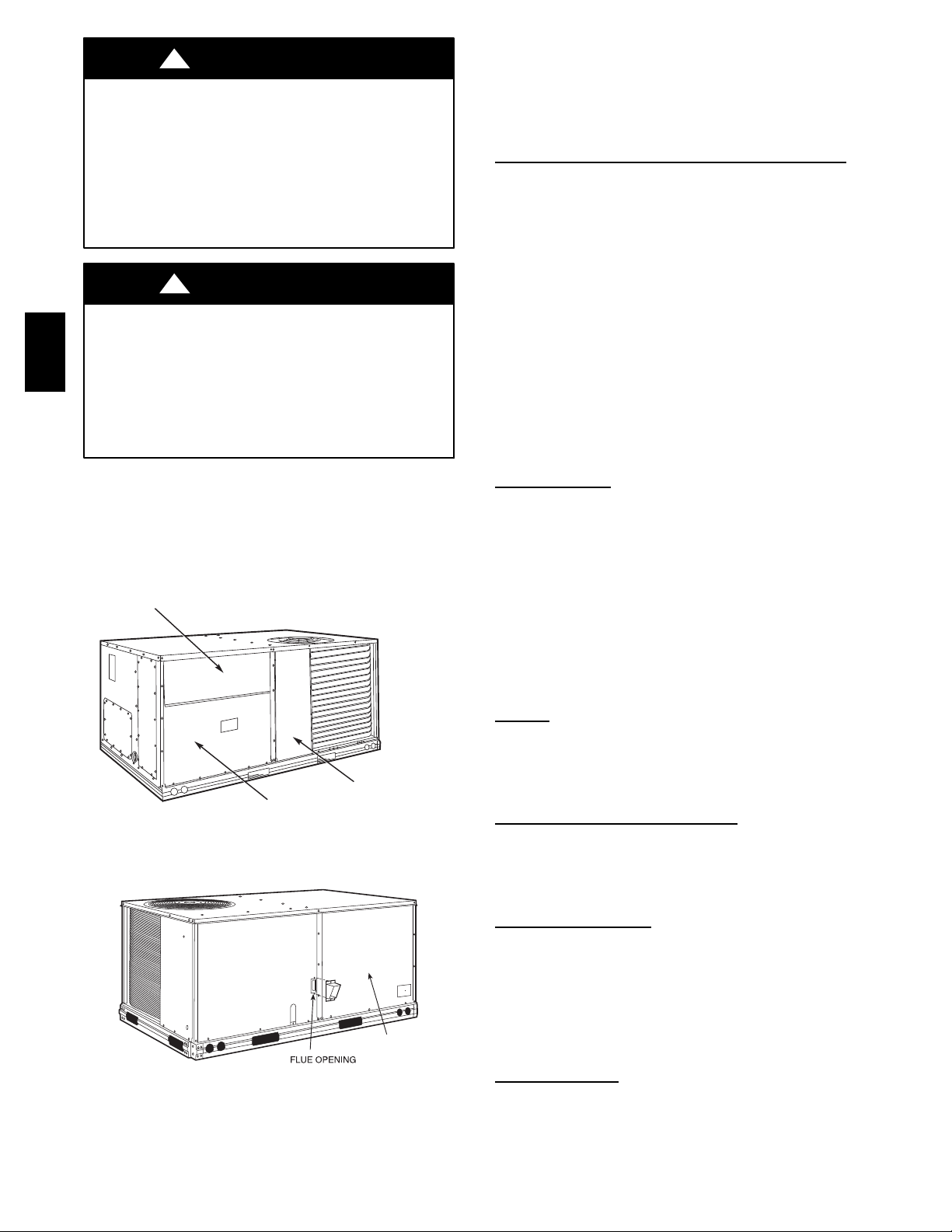
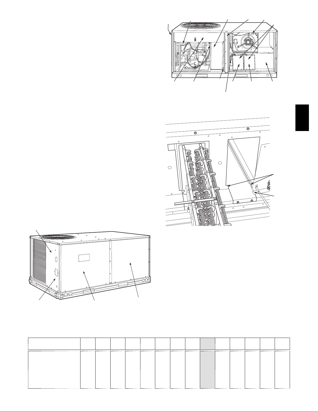
UNIT ARRANGEMENT AND ACCESS
General
Fig. 1 and 2 show general unit arrangement and access
locations.
FILTER ACCESS PANEL
Routine Maintenance
These items should be part of a routine maintenance
program, t o be checked every month or two, until a
specific schedule for each can be identified for this
installation:
Quarterly Inspection (and 30 days after initi al
start)
S Return air filter replacement
S Outdoor hood inlet filters cleaned
S Belt tension checked
S Belt condition checked
S Pulley alignment checked
S Fan shaft bearing locking collar tightness checked
S Condenser coil cleanliness checked
S Condensate drain checked
Seasonal Maintenance
These items should be checked at the beginning of each
season (or more often if local conditions and usage
patterns dictate):
Conditioning
Air
S Condenser fan motor mounting bolts tightness
S Compressor mounting bolts
S Condenser fan blade positioning
S Control box cleanliness and wiring condition
S Wire terminal tightness
S Refrigerant charge level
COMPRESSOR
ACCESS PANEL
OUTDOOR-AIR OPENING AND
INDOOR COIL ACCESS PANEL
Fig. 1 -- Typical Access Panel Locations
BLOWER
ACCESS
PANEL
Fig. 2 -- Blower Access Panel Location
C06023
C07081
S Evaporator coil cleaning
S Evaporator blower motor a mperage
Heating
S Power wire connections
S Fuses ready
S Manual--reset limit switch is closed
Economizer or Outside Air
Damper
S Inlet filters condition
S Check damper travel (economizer)
S Check gear and dampers for debris and dirt
Air Filters and Scr
eens
Each unit is equipped with return air filters. If the unit has
an economizer, it will also have an outside air screen. If a
manual outside air damper is added, an inlet air screen
will also be present.
Each of these filters and screens will need to be
periodically replaced or cleaned.
Return Air
Filters
Return air filters are disposable fiberglass media type.
Access to the filters is through the small lift--out panel
2
Page 3
located on the rear side of the unit, above the
R
evaporator/return air access panel. (See Fig. 1.)
To remove the filters:
1. Grasp the bottom flange of t he upper panel.
2. Lift up and swing the bottom out until the panel disengages and pulls out.
3. Reach inside and extract the filters from the filter
rack.
4. Replace these filters as required with similar replacement filters of same size.
To re--install the access panel:
1. Slide the top of the panel up under the unit top panel.
2. Slide the bottom into the side channels.
3. Push the bottom flange down until it contacts the top
of the lower panel (or economizer top).
IMPORTANT: DO NOT OPERATE THE UNIT
WITHOUT THESE FILTERS!
Outside Air
Hood
Outside air hood inlet screens are permanent
aluminum-- mesh type filters. Check these for cleanliness.
Remove the screens when cleaning is required. Clean by
washing with hot low--pressure water and soft detergent
and replace all screens before restarting the unit. Observe
the flow direction arrows on the side of each filter frame.
C07156
Fig. 4 -- Screens Installed on Outdoor--Air Hood
(Sizes 7--1/2 to 12--1/2 Tons Shown)
To remove the screen, loosen the screws in the top retainer
and slip the retainer up until the filter can be removed.
Re--install by placing the frame in its track, rotating the
retainer back down and tighten all screws.
50TC
Economizer Inlet Air Screen
This air screen is retained by spring c lips under the top
edge of the hood. (See Fig. 3.)
17 1/4”
DIVIDER
OUTSIDE
AIR
HOOD
CLEANABLE
BAROMETRIC
RELIEF
ALUMINUM
FILTER
FILTER
FILTE
CLIP
C06027
Fig. 3 -- Filter Installation
To remove the filter, open the spring clips. Re--install the
filter by placing the frame in its track, then closing the
spring clips.
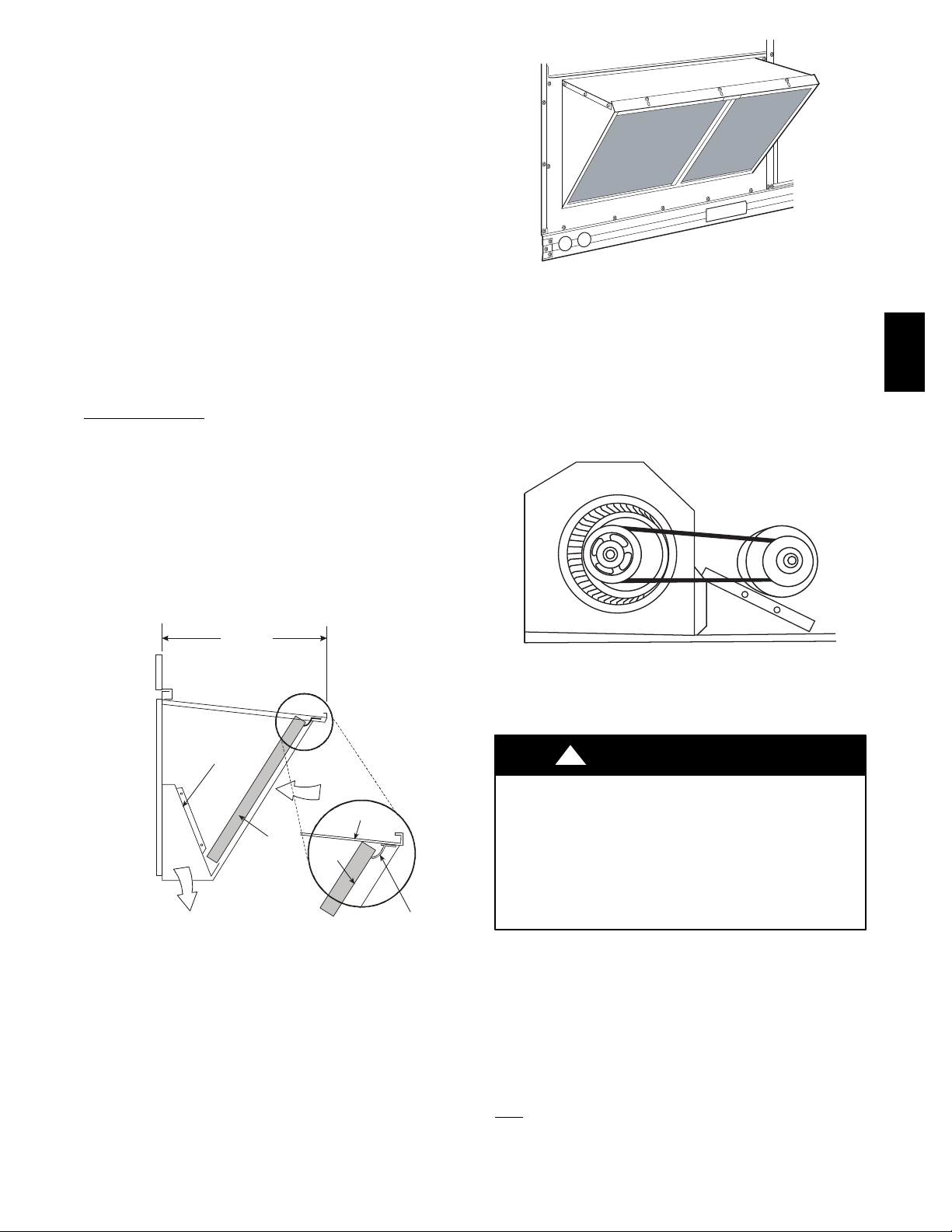
Manual Outside Air Hood Screen
This inlet screen is secured by a retainer angle across the
top edge of the hood. (See Fig. 4.)
C07087
Fig. 5 -- Belt Drive Motor Mounting
SUPPLY F AN (BLOWER) SECTION
!
WARNING
ELECTRICAL SHOCK HAZARD
Failure to follow this warning could cause personal
injury or death.
Before performing service or maintenance operations
on the fan system, shut off all unit power and tag--out
the unit disconnect switch. Do not reach into the fan
section with power still applied to unit.
Supply Fan (Belt--Drive)
The supply fan system consists of a forward--curved
centrifugal blower wheel on a solid shaft with two
concentric type bearings, one on each side of the blower
housing. A fixed--pitch driven pulley is attached to the fan
shaft and an adjustable--pitch driver pulley is on the
motor. The pulleys are connected using a “V” type belt.
(See Fig. 5.)
Belt
Check the belt condition and tension quarterly. Inspect the
belt for signs of cracking, fraying or glazing along the
3
Page 4
inside surfaces. Check belt tension by using a spring--force
tool (such as Browning’s Part Number “Belt Tension
Checker” or equivalent tool); tension should be 6--lbs at a
5/8--in. deflection when measured at the centerline of the
belt span. This point is at the center of the belt when
measuring the dista nce between the motor shaft and the
blower shaft.
NOTE: Without the spring--tension tool, place a straight
edge across the belt surface at the pulleys, then de f lect the
belt at m id--span using one finger to a 1/2--in. deflection.
Adjust belt tension by loosening the motor mounting plate
front bolts and rear bolt and sliding the plate toward the
fan (to reduce tension) or away from fan (to increase
tension). Ensure the blower shaft and the motor shaft are
parallel to each other (pulleys aligned). Tighten all bolts
when finished.
To replace the belt:
50TC
1. Use a belt with same section type or similar size. Do
not substitute a “FHP” type belt. When installing the
new belt, do not use a tool (screwdriver or pry--bar) to
force the belt over the pulley flanges, this will stress
the belt and cause a reduction in belt life.
2. Loose n the motor mounting plate front bolts and rear
bolts.
3. Push the motor and its mounting plate towards the
blower housing as close as possible to reduce the center distance between fan shaft and motor shaft.
4. Re move the belt by gently lifting the old belt over
one of the pulleys.
5. Install the new belt by gently sliding the belt over
both pulleys and then sliding the motor and plate
away from the fa n housing until prope r tension is
achieved.
6. Check the alignment of the pulleys, adjust if necessary.
7. Tighte n all bolts.
8. Check the t ension after a few hours of runtime and
re--adjust as required.
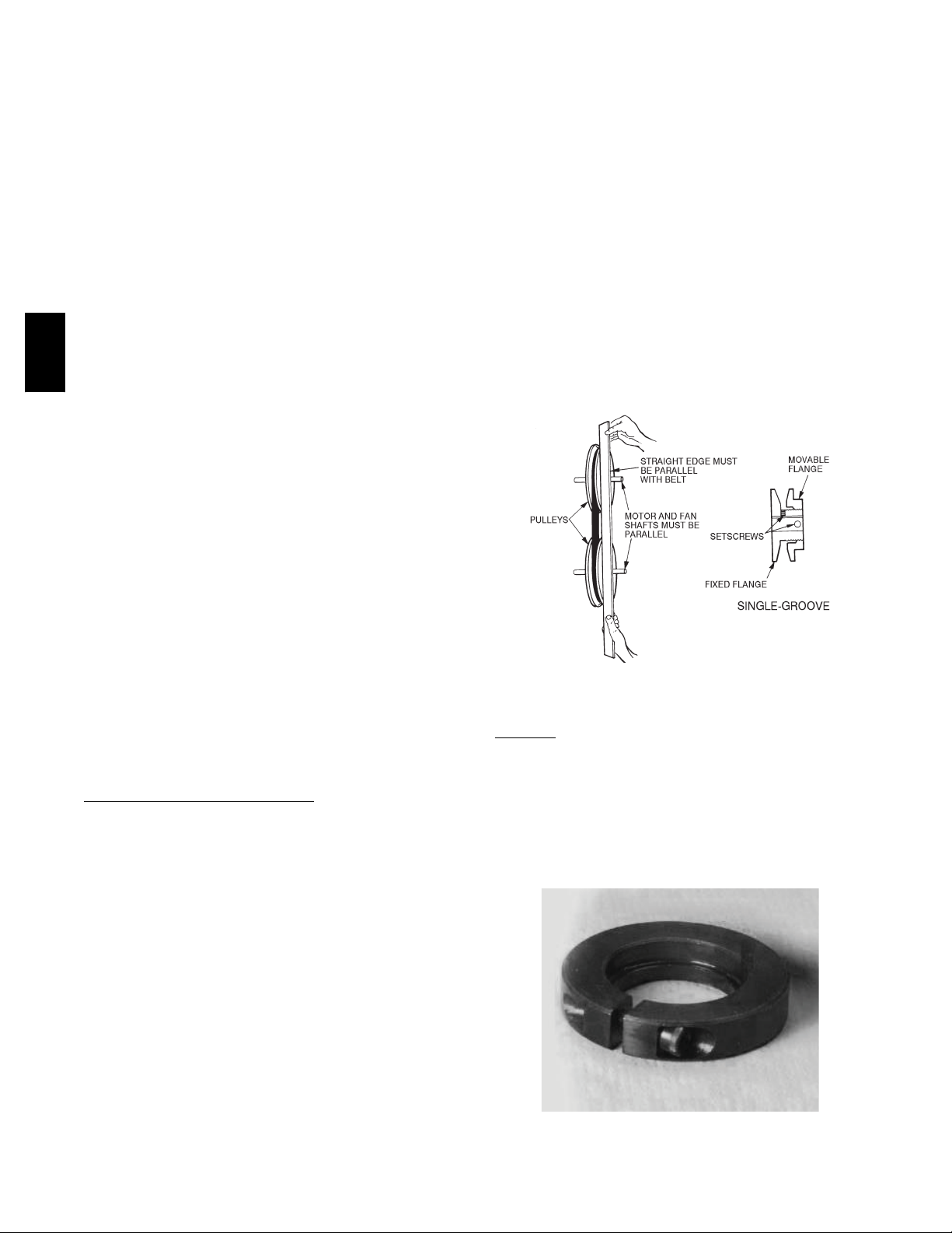
Adjustable--Pitch Pulley on
Motor
The motor pulley is an adjustable--pitch type that allows a
servicer to implement changes in the fan wheel speed to
match as--installed ductwork systems. The pulley consists
of a fixed flange side that faces the motor (secured to the
motor shaft) and a movable flange side that can be rotated
around the fixed flange side that increases or reduces the
pitch diameter of this driver pulley. (See Fig. 6.)
To change fan speed:
1. Shut off unit power supply.
2. Loose n belt by loosening fan motor mounting nuts.
(See Fig. 5.)
3. Loose n movable pulley flange setscrew. (See Fig. 6.)
4. Screw movable flange toward fixed flange to increase
speed and away from fixed flange to decrease speed.
Increasing fan speed increases load on motor. Do not
exceed maximum speed specified.
5. Set movable flange at nearest keyway of pulley hub
and tighten setscrew to torque specifications.
To align fan and motor pulleys:
1. Loosen fan pulley setscrews.
2. Slide fan pulley along fan shaft. Make angular alignment by loosening motor from mounting.
3. Tighten fan pulley setscrews and motor mounting
bolts to torque specifications.
4. Re check belt tension.
C07075
Fig. 6 -- Supply--Fan Pulley Adjustment
Bearings
This fan system uses bearings featuring concentric split
locking collars. The collars are tightened through a cap
screw bridging the split portion of the collar. The cap
screw has a Torx T25 socket head. To tighten the locking
collar: Hold the locking collar tightly against the inner
race of the bearing and torque the cap screw to 65--70
in--lb (7.4--7.9 Nm). See Fig. 7.
As the pitch diameter is changed by adjusting the position
of the movable flange, the centerline on this pulley shifts
laterally (along the motor shaft). This creates a
requirement for a realignment of the pulleys a fter any
adjustment of the movable flange. Also reset the belt
tension after each realignment.
Check the condition of the motor pulley for signs of wear.
Glazing of the belt contact surfaces and erosion on these
surfaces are signs of improper belt tension and/or belt
slippage. Pulley replacement may be necessary.
C08121
Fig. 7 -- Tightening Locking Collar
4
Page 5

Motor
When replacing the motor, also replace the external--tooth
lock washer (star washer) under the motor mounting base;
this is part of the motor grounding system. Ensure the
teeth on the lock washer are in contact with the motor ’s
painted base. Tighten motor mounting bolts to 120 +/ -- 12
in--lbs.
Changing fan wheel speed by changing pulleys: The
horsepower rating of the belt is primarily dic tated by the
pitch diameter of the smaller pulley in the drive system
(typically the motor pulley in these units). Do not install a
replacement motor pulley with a smaller pitch diameter
than provided on the original factory pulley. Change fan
wheel speed by changing the fan pulley (larger pitch
diameter to reduce wheel speed, smaller pitch diameter to
increase wheel speed) or select a new system (both
pulleys and matching belt(s)).
Before changing pulleys to increase fan wheel speed,
check the fan performance at the target speed and airflow
rate to dete rmine new motor loading (bhp). Use the fan
performance tables or use the Packaged Rooftop Builder
software program. Confirm that the motor in this unit is
capable of operating a t the new operating condition. Fan
shaft loading increases dramatically as wheel speed is
increased.
To reduce vibration, replace the motor’s adjustable pitch
pulley with a fixed pitch pulley (after the final airflow
balance adjustment). This will reduce the amount of
vibration generated by the motor/belt--drive system.
COOLING
!
WARNING
UNIT OPERATION AND SAFETY HAZARD
Failure to follow this warning could cause personal
injury, death and/or equipment damage.
This system uses PuronR refrigerant which has
higher pressures than R--22 and other refrigerants. No
other refrigerant may be used in this system. Gauge
set, hoses, and recovery system m ust be designed to
handle Puron refrigerant. If unsure about equipment,
consult the equipment manufacturer.
Condenser Coil
The condenser coil is fabricated with round tube copper
hairpins and plate fins of various materials and/or coatings
(see Model Number Format in the Appendix to identify
the materials provided in this unit). The coil may be
one--row or composite--type two--row. Composite two--row
coils are two single--row coils fabricated with a single
return bend end tubesheet.
Condenser Coil Maintenance and Cleaning
Recommendation
Routine cleaning of coil surfaces is essential to maintain
proper operation of the unit. Elimination of contamination
and removal of harmful residues will greatly increase the
life of the coil and extend the life of the unit. The
following maintenance and cleaning procedures are
recommended as part of the routine maintenance activities
to extend the life of the coil.
Remove Surface Loaded
Surface loaded fibers or dirt should be removed with a
vacuum cleaner. If a vacuum cleaner is not available, a
soft non--metallic bristle brush may be used. In either
case, the tool should be applie d in the direction of the fins.
Coil surfaces can be easily damaged (fin edges can be
easily bent over and damage to the coating of a protected
coil) if the tool is applied across the fins.
NOTE: Use of a water stream, such as a garden hose,
against a surface loaded coil will drive the fibers and dirt
into the coil. This will make cleaning efforts more
difficult. Surface loaded fibers must be completely
removed prior to using low velocity clean water rinse.
Periodic Clean Water
A periodic clean water rinse is very beneficial for coils
that are applied in coastal or industrial environments.
However, it is very important that the water rinse is made
with a very low velocity water stream to avoid damaging
the fin edges. Monthly cleaning as described below is
recommended.
Routine Cleaning of Coil
Periodic cleaning with TotalineR environmentally sound
coil cleaner is essential to extend the life of coils. This
cleaner is available from Carrier Replacement
Components Division as part number P902--0301 for a one
gallon container, and part number P902--0305 for a 5
gallon container. It is recommended that all coils,
including standard a luminum, pre--coated, copper/copper
or E--coated coils be cleaned with the Totaline
environmentally sound coil cleaner as describe d below.
Coil cleaning should be part of the unit’s regularly
scheduled maintenance procedures to ensure long life of
the coil. Failure to clean the coils may result in reduced
durability in the environment.
Avoid use of:
S coil brighteners
S acid cleaning prior to painting
S hi gh pressure washers
S poor quality water for cleaning
Totaline environmenta lly sound coil cleane r is
nonflammable, hypo allergenic, non bacteri al, and a
USDA accepted biodegradable agent that will not harm
the coil or surrounding components such as electrical
wiring, painted metal surfaces, or insulation. Use of
non--recomm ended coil cleaners is strongly discouraged
since coil and unit durability could be affected.
One--Row Coil
Wash coil with commercial coil cleaner. It is not
necessary to remove top panel.
Fibers
Rinse
Surfaces
50TC
5
Page 6
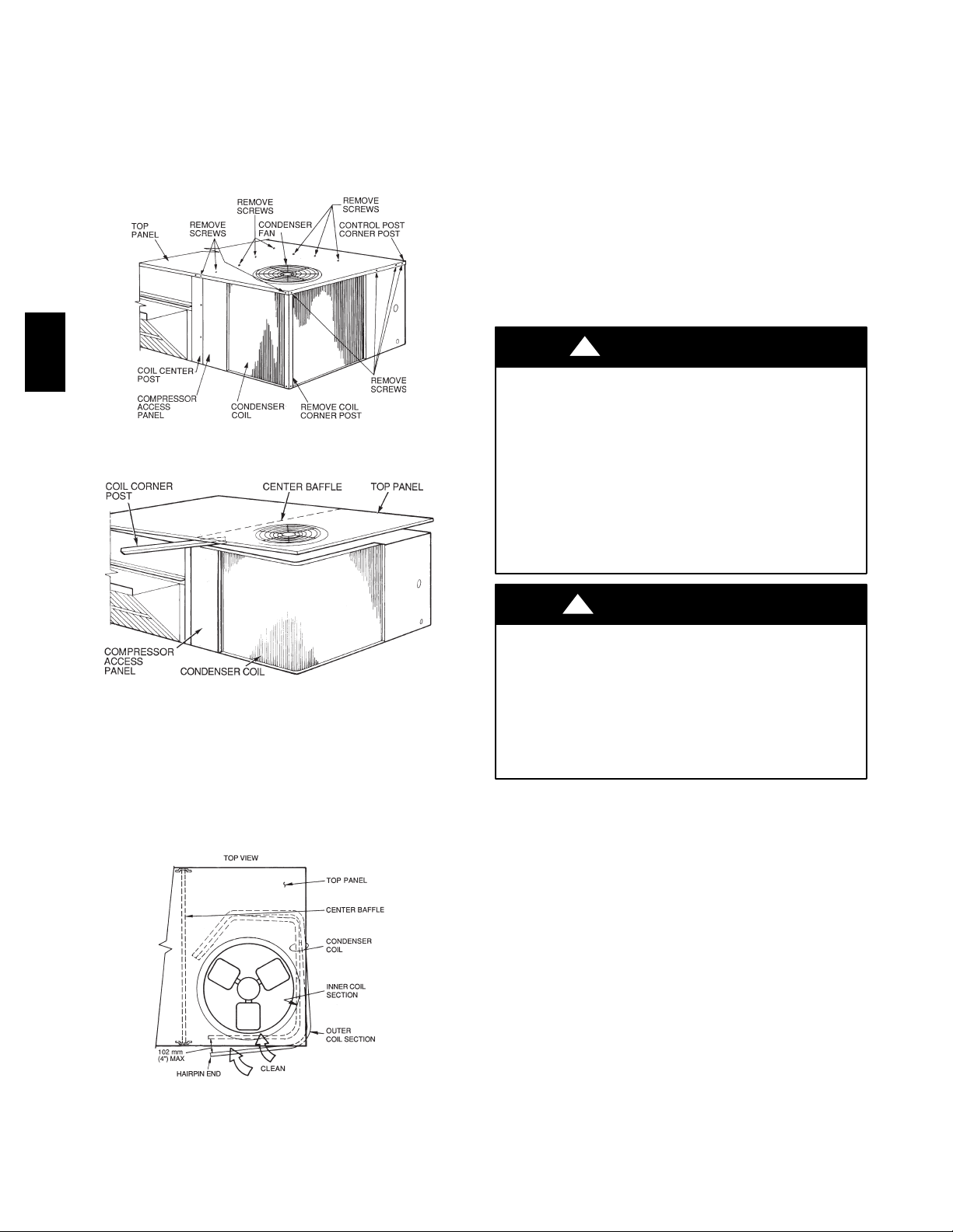
Two--Row Coils
Clean coil as follows:
1. Turn off unit power, tag disconnect.
2. Re move top panel screws on condenser end of unit.
3. Re move condenser coil corner post. See Fig. 8. To
hold top panel open, place coil corner post between
top panel and center post. See Fig. 9.
50TC
Fig. 8 -- Cleaning Condenser Coil
C08205
6. Use a water hose or other suitable equipment to flush
down between the 2 coil sections to remove dirt and
debris. Clean the outer surfaces with a stiff brush in
the normal manner.
7. Secure inner and outer coil rows together with a
field--supplied fastener.
8. Reposition the outer coil section and remove the coil
corner post from between the top panel and center
post. Reinstall the coil corner post and replace all
screws.
Totaline Environmentally Sound Coil Cleaner
Application Equipment
S 2--1/2 gallon garden sprayer
S Water rinse with low velocity spray nozzle
!
CAUTION
UNIT DAMAGE HAZARD
Failure to follow this caution may result in accelerated
corrosion of unit parts.
Harsh chemicals, household bleach or acid or basic
cleaners should not be used to clean outdoor or indoor
coils of any kind. These cleaners can be very difficult
to rinse out of the coil and can accelerate corrosion at
the fin/tube interface where dissimilar materials are in
contact. If there is dirt below the surface of the coil,
use the Totaline e nvironmentally sound coil cleaner.
C08206
Fig. 9 -- Propping Up T op Panel
4. Remove screws securing coil to compressor plate and
compressor access panel.
5. Re move fastener holding coil sections together at return end of condenser coil. Carefully separate the outer coil section 3 to 4 in. from the inner coil section.
See Fig. 10.
C08207
Fig. 10 -- Separating Coil Sections
!
CAUTION
UNIT DAMAGE HAZARD
Failure to follow this caution may result in reduced
unit performance or unit shutdown.
High velocity water from a pressure washer, garden
hose, or compressed air should never be used to
clean a coil. The force of the water or air jet will
bend the fin edges and increase airside pressure drop.
Totaline Environmentally Sound Coil Cleaner
Application Instructions
1. Proper eye protection such as safety glasses is recommended during mixing and application.
2. Remove all surface loaded fibers and dirt with a vacuum
cleaner as described above.
3. Thoroughly wet finned surfaces with clean water and
a low velocity garden hose, being careful not t o bend
fins.
4. Mix Totaline environmentally sound coil cleaner in a
2--1/2 gallon garden sprayer according to the instructions included with the cleaner. The optimum solution
temperature is 100_F.
NOTE: Do NOT USE water in excess of 130_F, a s t he
enzymatic activity will be destroyed.
5. Thoroughly apply Totaline environmentally sound
coil cleaner solution to all coil surfaces including
finned area, tube sheets and coil headers.
6
Page 7

6. Hold garden sprayer nozzle close to finned areas and
apply cleaner with a vertical, up--and--down mot ion.
Avoid spraying in horizontal pattern to minimize potential for fin damage.
7. Ensure cleaner thoroughly penetrates deep into finned
areas.
8. Interior and exterior finned areas must be thoroughly
cleaned.
9. Finned surfaces should remain wet with cleaning
solution for 10 minutes.
10. Ensure surfaces are not allowed to dry before rinsing.
Reapplying cleaner as needed to ensure 10--minute
saturation is achieved.
11. Thoroughly rinse all surfaces with low velocity clean
water using downward rinsing motion of water spray
nozzle. Protect fins from damage from the spray
nozzle.
Evaporator Coil
Cleaning the Evaporator Coil
1. Turn unit power off. Install lockout tag. Remove
evaporator coil access panel.
2. If economizer or two--position damper is installed, remove economizer by disconnecting Molex plug and
removing mounting screws.
3. Slide filters out of unit.
4. Clean coil using a commercial coil cleaner or dishwasher detergent in a pressurized spray canister. Wash
both sides of coil and flush with clean water. For best
results, back--flush toward return--air section to remove foreign material. Flush condensate pan after
completion.
5. Reinstall economizer and filters.
6. Re connect wiring.
7. Replace access panels.
Evaporator Coil M etering
The metering devices are multiple fixed--bore devices
(Acutrolt) wedged into the horizontal outlet tubes from
the liquid header, located at the entrance to each
evaporator coil circuit path. These are non--adjustable.
Service requires replacing the entire liquid header
assembly.
To check for possible blockage of one or more of these
metering devices, disconnect the supply fan contactor
(IFC) coil, then start the compressor and observe the
frosting pattern on the face of the evaporator coil. A frost
pattern should develop uniformly across the face of the
coil starting at each horizontal header tube. Failure to
develop frost at an outle t tube can indicate a plugged or a
missing orifice.
Devices
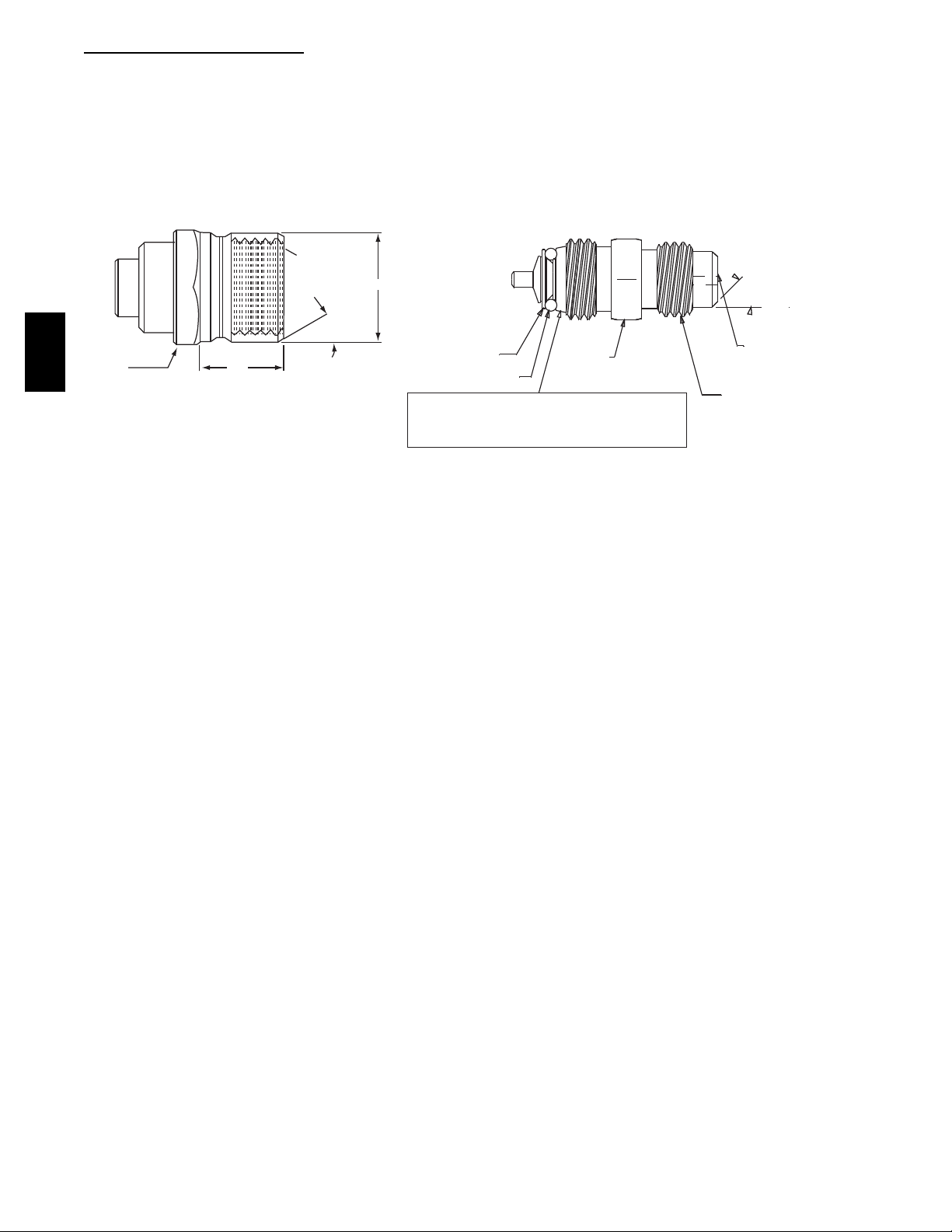
Refrigerant System Pressure Access Ports
There are two access ports in the system -- on the suction
tube near the compressor and on the discharge tube near
the compressor. These are brass fittings with black plastic
caps. The hose connection fittings are standard 1/4 SAE
Male Flare couplings.
The brass fittings are two--piece High Flow valves, with a
receptacle base brazed to the tubing and an integral
spring--closed check valve core screwed into the base.
(See Fig. 11.) This check valve is permanently assembled
into this core body and cannot be serviced separately;
replace the entire core body if necessary. Service tools are
available from RCD that allow the replacement of the
check valve core without having to re cover the entire
system refrigerant charge. Apply compressor refrigera nt
oil to the check valve core’s bottom o--ring. Install the
fitting body with 96 +/ --10 in -- lbs of t orque; do not
overtighten.
PURONR (R--410A) REFRIGERANT
This unit is designed for use with Puron (R--410A)
refrigerant. Do not use any other refrigerant in this
system.
Puron (R--410A) is provided in pink (rose) colored
cylinders. These cylinders are available with and without
dip tubes; cylinders wit h dip tubes will have a label
indicating this feature. For a cylinder with a dip tube,
place the cylinder in the upright position (access valve at
the top) when removing liquid refrigerant for charging.
For a cylinder without a dip tube, invert the cylinder
(access valve on the bottom) when removing liquid
refrigerant.
Because Puron (R--410A) is a blend, it is strongly
recommended t hat refrigerant always be removed from
the cylinder as a liquid. Admit liquid refrigerant into the
system in the discharge line. If adding refrigerant into the
suction line, use a commercial metering/expansion device
at the gauge manifold; remove liquid from the cylinder,
pass it t hrough the metering device at the gauge set and
then pass it into the suction line as a vapor. Do not remove
Puron (R--410A) from the cylinder as a vapor.
Refrigerant Charge
Amount of refrigerant charge is listed on the unit’s
nameplate. Refer to Carrier GTAC2--5 Charging,
Recovery, Recycling and Reclamation training manual
and the following procedures.
Unit panels must be in place when unit is operating during
the charging procedure.
Charge
No
Use standard evacuating techniques. After evacuating
system, weigh in the specified amount of refrigerant.
Low--Charge
Using Cooling Charging Charts, Fig. 12, vary refrigerant
until the conditions of the appropriate chart are met. Note
the charging charts are different from type normally used.
Charts are based on charging the units to the correct
superheat for t he various operating conditions. Accurate
pressure gauge and temperature sensing device are
required. Connect the pressure gauge to the service port
on the suction line. Mount t he temperature sensing de vice
on the suction line and insulate it so that outdoor ambient
temperature does not affect the reading. Indoor--ai r cfm
must be within the normal operating range of the unit.
7
Cooling
50TC
Page 8
To Use Cooling Charging Charts
Take the outdoor ambient temperature and read the
suction pressure gauge. Refer to chart to determine what
suction temperature should be. If suction temperature is
high, add refrigerant. If suction temperature is low,
carefully recover some of the charge. Recheck the suction
pressure as charge is adjusted.
1/2-20 UNF RH
EXAMPLE:
Model 50TC*A06
Outdoor Temperature 85_F(29_C)..................
Suction Pressure 130 psig (896 kPa).................
Suction Temperature should be 63_F (17.2_C).........
50TC
5/8” HEX
.47
SEAT
0.596
o
30
WASHER
O-RING
This surface provides a metal to metal seal when
torqued into the seat. Appropriate handling is
required to not scratch or dent the surface.
Fig. 11 -- CoreMax Access Port Assembly
1/2" HEX
CORE
o
45
DEPRESSOR PER ARI 720
+.01/-.035
FROM FACE OF BODY
7/16-20 UNF RH
C07150
8
Page 9
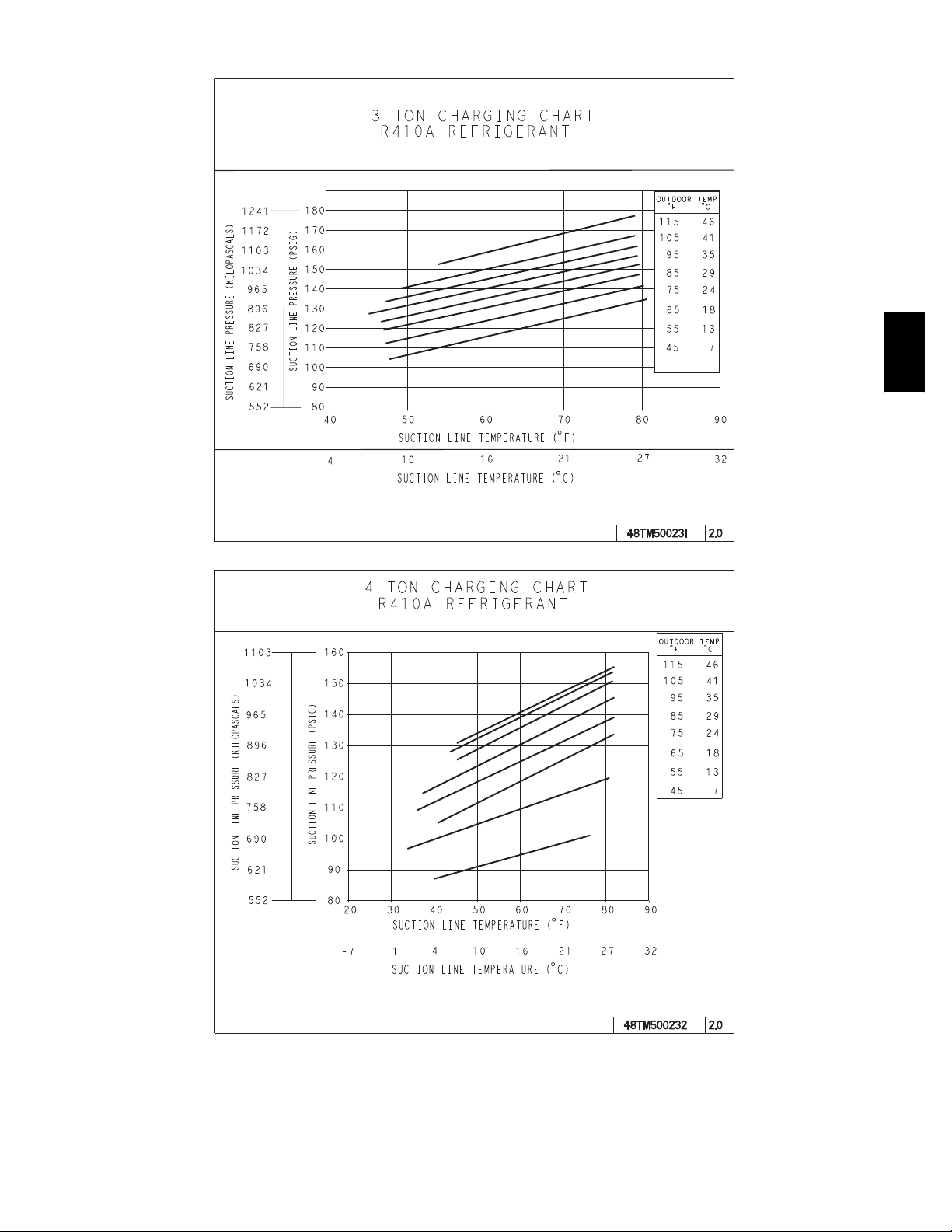
COOLING CHARGING CHARTS
50TC
C08203
Fig. 12 -- Cooling Charging Charts
9
C08204
Page 10
50TC
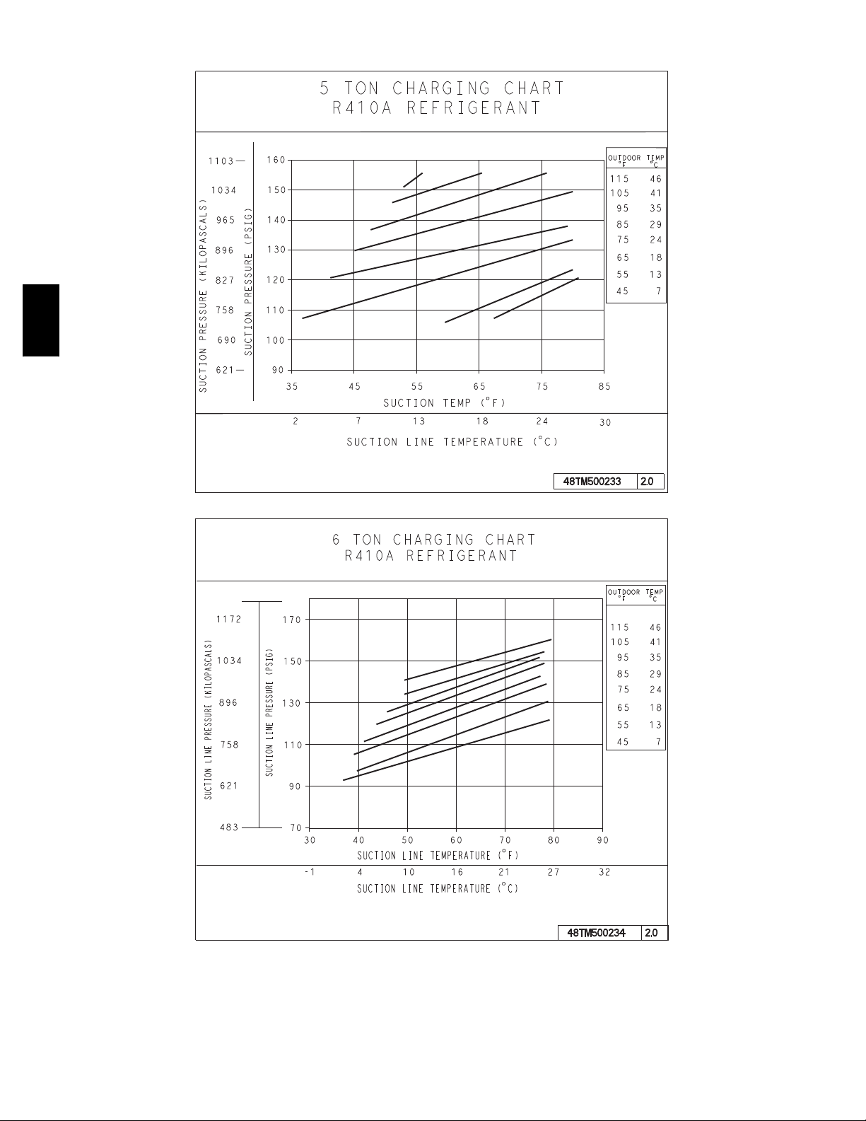
COOLING CHARGING CHARTS (cont)
C08228
Fig. 12 -- Cooling Charging Charts (cont.)
10
C08229
Page 11
Compressor
Lubrication
The compressor is charged with t he correct amount of oil
at the factory.
!
CAUTION
UNIT DAMAGE HAZARD
Failure to follow this caution may result in damage to
components.
The compressor is in a PuronR refrigerant system and
uses a polyolester (POE) oil. This oil is extremely
hygroscopic, meaning it absorbs water readily. POE
oils can absorb 15 times as much water as other oils
designed for HCFC and CFC refri gerants. Avoid
exposure of the oil to the atmosphere.
Replacing Compressor
The compressor used with Puron refrigerant c ontains a
POE oil. This oil has a high affinity for moisture. Do not
remove the compressor’s tube plugs until ready to insert
the unit suction and discharge tube ends.
Compressor mounting bolt torque is 65--75 ft--lbs.
The suction and discharge pressure levels should now
move to their normal start--up levels.
NOTE: When the compressor is rotating in the wrong
direction, the unit makes an elevated level of noise and
does not provide cooling.
Filter Drier
Replace whenever refrigerant system is exposed to
atmosphere. Only use factory specified liquid--line filter
driers with working pressures no less than 650 psig. Do
not install a suction--line filter drier in liquid line. A
liquid--line filter drier designed for use with Puron
refrigerant is re quired on every unit.
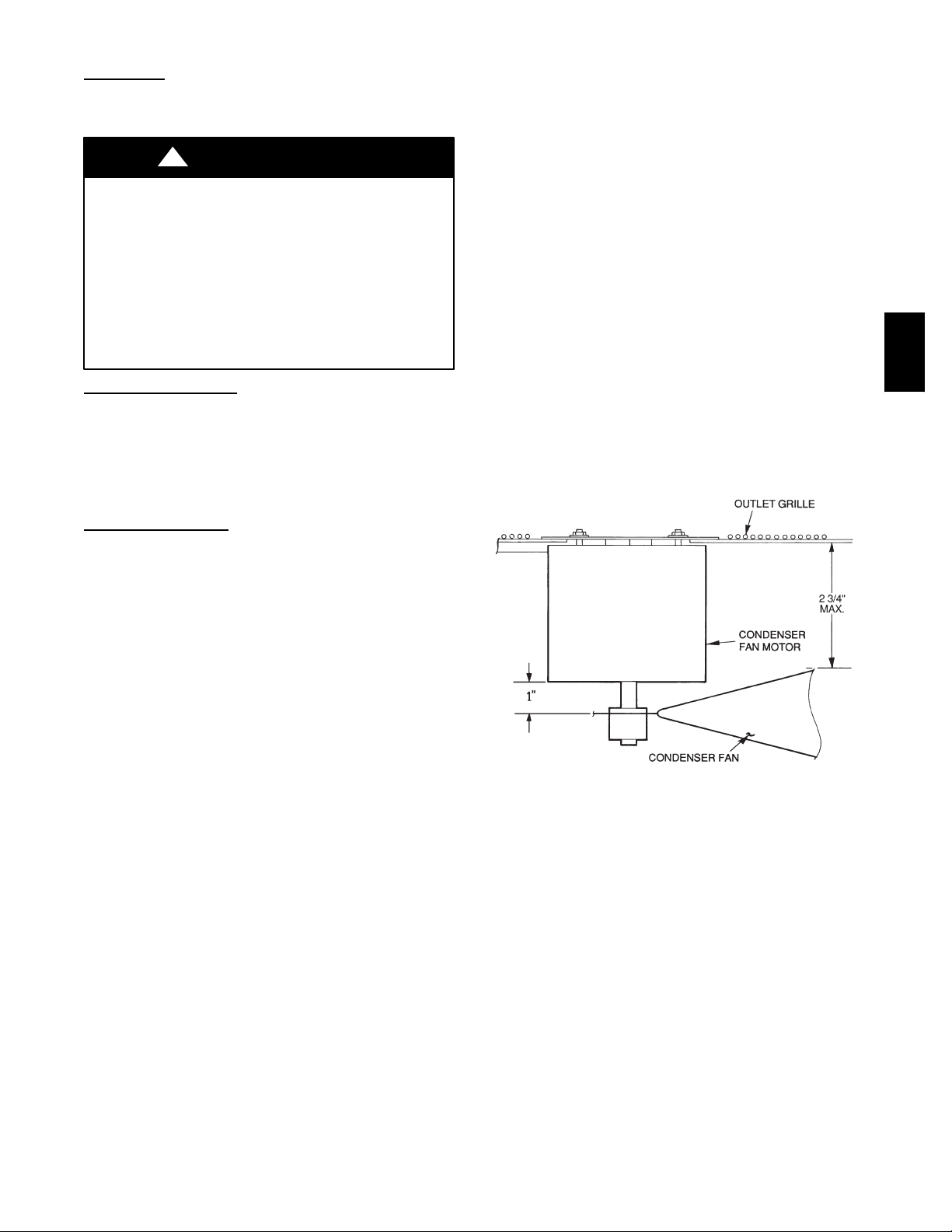
Condenser--Fan Location
See Fig. 13.
1. Shut off unit power supply. Install lockout tag.
2. Remove condenser--fan assembly (grille, motor, and
fan).
3. Loosen fan hub setscrews.
4. Adjust fan height as shown in Fig. 13.
5. Tighten setscrews.
6. Re place condenser--fan assembly.
50TC
Compressor
On 3--phase units with scroll compressors, it is important
to be certain compressor is rotating in the proper
direction. To dete rmine whether or not compressor is
rotating in t he proper direction:
1. Conne ct service gauges to suction and discharge pressure fittings.
2. Energize the compressor.
3. The suction pressure should drop and the discharge
pressure should rise, as is normal on any start--up.
NOTE: If t he suction pressure does not drop and the
discharge pressure does not rise to normal levels:
4. Note that the evaporator fan is probably also rotating
in the wrong direction.
5. Turn off power to the unit.
6. Re verse any two of the unit power leads.
7. Re apply power to the compressor.
Rotation
C07091
Fig. 13 -- Condenser Fan Adjustment
(except with Motormaster)
Troubleshooting Cooling System
Refer to Table 1 for additional troubleshooting topics.
11
Page 12

Table 1 – Cooling Service Analysis
PROBLEM CAUSE REMEDY
Power failure. Call power company.
Fuse blown or circuit breaker tripped. Replace fuse or reset circuit breaker.
Compressor and Condenser
Fan Will Not Start.
Compressor Will Not Start But
Condenser Fan Runs.
50TC
Compressor Cycles (other
than normally satisfying thermostat).
Compressor Operates
Continuously.
Excessive Head Pressure.
Head Pressure Too Low.
Excessive Suction Pressure.
Suction Pressure Too Low.
Evaporator Fan Will Not Shut
Off.
Compressor Makes Excessive
Noise.
Defective thermostat, contactor, transformer,
or control relay.
Insufficient line voltage. Determine cause and correct.
Incorrect or faulty wiring. Check wiring diagram and rewire correctly.
Thermostat setting too high. Lower thermostat setting below room temperature.
Faulty wiring or loose connections in compres-
sor circuit.
Compressor motor burned out, seized, or
internal overload open.
Defective run/start capacitor, overload, start
relay.
Onelegofthree---phasepowerdead.
Refrigerant overcharge or undercharge.
Defective compressor. Replace and determine cause.
Insufficient line voltage. Determine cause and correct.
Blocked condenser. Determine cause and correct.
Defective run/start capacitor, overload, or start
relay.
Defective thermostat. Replace thermostat.
Faulty condenser--- fan motor or capacitor. Replace.
Restriction in refrigerant system. Locate restriction and remove.
Dirty air filter. Replace filter.
Unit undersized for load. Decrease load or increase unit size.
Thermostat set too low. Reset thermostat.
Low refrigerant charge. Locate leak; repair and recharge.
Leaking valves in compressor. Replace compressor.
Air in system. Recover refrigerant, evacuate system, and recharge.
Condenser coil dirty or restricted. Clean coil or remove restriction.
Dirty air filter. Replace filter.
Dirty condenser coil. Clean coil.
Refrigerant overcharged. Recover excess refrigerant.
Air in system. Recover refrigerant, evacuate system, and recharge.
Condenser air restricted or air short --- cycling. Determine cause and correct.
Low refrigerant charge. Check for leaks; repair and recharge.
Compressor valves leaking. Replace compressor.
Restrictioninliquidtube. Remove restriction.
High head load. Check for source and eliminate.
Compressor valves leaking. Replace compressor.
Refrigerant overcharged. Recover excess refrigerant.
Dirty air filter. Replace filter.
Low refrigerant charge. Check for leaks; repair and recharge.
Metering device or low side restricted. Remove source of restriction.
Insufficient evaporator airflow.
Temperature too low in conditioned area. Reset thermostat.
Outdoor ambient below 25˚F. Install low---ambient kit.
Time off delay not finished. W a i t f o r 3 0 --- s e con d o f f delay.
Compressor rotating in wrong direction. Reversethe3---phasepowerleads.
Replace component.
Check wiring and repair or replace.
Determine cause. Replace compressor.
Determine cause and replace.
Replace fuse or reset circuit breaker. Determine
cause.
Recover refrigerant, evacuate system, and recharge
to nameplate.
Determine cause and replace.
Increase air quantity. Check filter and replace if
necessary.
12
Page 13
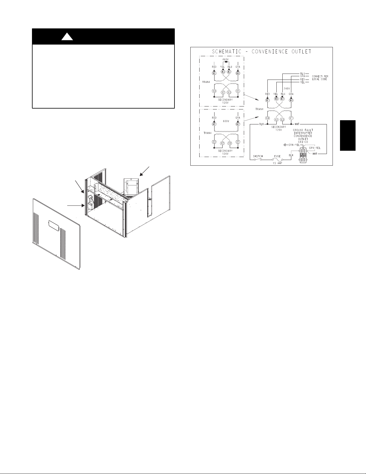
CONVENIENCE OUTLETS
!
WARNING
ELECTRICAL OPERATION HAZARD
Failure to follow this warning could result in personal
injury or death.
Units with convenience outlet circuits may use
multiple disconnects. Check convenience outlet for
power status before opening unit for service. Locate
its disconnect switch, if appropriate, and open it.
Tag--out this switch, if necessary.
Two types of convenience outlets are offered on 50TC
models: Non--powered and unit--powered. Both types
provide a 125--volt GFCI (ground--fault
circuit--interrupter) duplex receptacle rated at 15--A
behind a hinged waterproof access cover, located on the
end panel of the unit. See Fig. 14.
Pwd-CO Transformer
Conv Outlet
GFCI
or HACR switch is open. Other connection methods will
result in the convenience outlet circuit being de--energized
when the unit disconnect or HACR switch is open. See
Fig. 15.
50TC
CO8283
Fig. 15 -- Powered Convenience Outlet Wiring
Pwd-CO
Fuse
Switch
C08128
Fig. 14 -- Convenience Outlet Location
Non--powered type: This type requires the field
installation of a general--purpose 125--volt 15--A circuit
powered from a source elsewhere in the building. Observe
national and loca l codes when selecting wire size, fuse or
breaker requirements and disconnect switch size and
location. Route 125--v power supply conductors into the
bottom of the utility box containing the duplex receptacle.
Unit--powered type: A unit--mounted transformer is
factory--i nstalled to stepdown the main power supply
voltage to the unit to 115--v at the duplex receptacle. This
option also includes a manual switch with fuse, located in
a utility box and m ounted on a bracket behind the
convenience outlet; access is through the unit’s control
box access panel. See Fig. 14.
The primary leads to the convenience outlet transformer
are not factory--connected. Selection of primary power
source is a customer--option. If local codes permit, the
transformer primary leads can be connected at the
line--side terminals on a unit--mounted non--fused
disconnect or HACR breaker switch; this will provide
service power to the unit when the unit disconnect switch
Duty Cycle: The unit--powered convenience outlet has a
duty cycle limitation. The transformer is intended to
provide power on an intermittent basis for service tools,
lamps, etc; it is not intended to provide 15 --amps loading
for continuous duty loads (such as electric heaters for
overnight use). Observe a 50% limit on circuit loading
above 8--amps (i.e., limit loads exceeding 8--amps to 30
minutes of operation every hour).
Maintenance: Periodically test the GFCI receptacle by
pressing the TEST button on the face of the receptacle.
This should cause the internal circuit of the receptacle to
trip and open the receptacle. Check for proper grounding
wires and power line phasing if the GFCI receptacle does
not trip as re quired. Press the RESET button to clear the
tripped condition.
Fuse on powered type: The factory fuse is a Bussman
“Fusetron” T--15, non-- renewable screw--in (Edison base)
type plug fuse.
Using unit--mounted convenience outlets: Units with
unit--mounted convenience outlet circuits will often
require that two disconnects be opened to de--energize all
power to the unit. Treat all units as electrically energized
until the convenience outlet power is also checked and
de--energization is confirmed. Observe National Electrical
Code Article 210, Branch Circuits, for use of c onvenience
outlets.
SMOKE DETECTORS
Smoke detectors are available as factory--installed opt ions
on 50TC models. Smoke detectors may be specified for
Supply Air only or for Return Air without or with
economizer or in combination of Supply Air and Return
Air. Return Air smoke detectors are arranged for vertical
return configurations only. All components necessary for
13
Page 14
operation are factory--provided and mounted. The unit is
factory-- configured for immediate smoke detector
shutdown operation; additional wiring or modifications t o
unit terminal board may be necessary to complete the unit
and smoke detector configuration to meet project
requirements.
System
The smoke detector system consists of a four--wire
controller and one or two sensors. Its primary function is
to shut down the rooftop unit in order to prevent smoke
from circulating throughout the building. It is not to be
used as a life saving device.
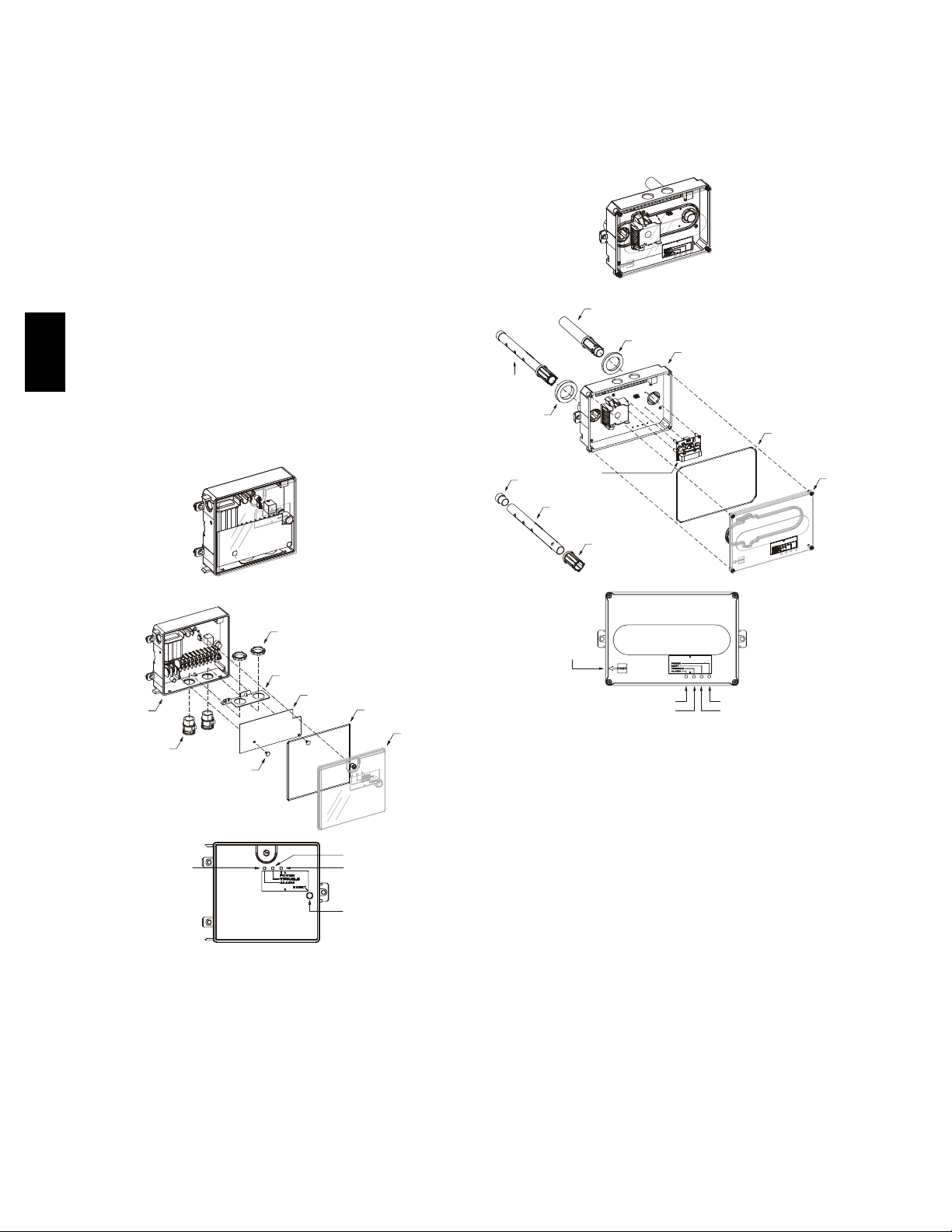
Controller
The controller (see Fig. 16) includes a controller housing,
a printed circuit board, and a clear plastic cover. The
controller can be connected to one or two compatible duct
50TC
smoke sensors. The clear plastic cover is secured to the
housing with a single captive screw for easy access to the
wiring terminals. The controller has three LEDs (for
Power, Trouble and Alarm) and a manual test/reset button
(on the cover face).
inspections without having to disassemble the sensor. The
cover attaches to the sensor housing using four captive
screws and forms an airtight chamber around the sensing
electronics. Each sensor includes a harness with an RJ45
terminal for connecting to the controller. Each sensor has
four LEDs (for Power, Trouble, Alarm and Dirty) and a
manual test/reset button (on the left--side of the housing).
Duct smoke sensor
Exhaust tube
See
Detail A
Intake
gasket
Plug
TSD-CO2
(ordering option)
Sampling tube
(ordered separately)
Exhaust gasket
Sensor housing
and electronics
Cover gasket
(ordering option)
Sensor cover
Duct smoke sensor
controller
Conduit nuts
(supplie d by installer)
Conduit s upport plate
Controll er housing
and electronics
Conduit c ouplings
(supplie d by installer)
Alarm
Fastener
(2X)
Terminal block cover
Troub le
Power
Tes t / r e s e t
switch
Cover gasket
(ordering option)
Controll er cover
C08208
Fig. 16 -- Controller Assembly
Sensor
The sensor (see Fig. 17) includes a plastic housing, a
printed circuit board, a clear plastic cover, a sampling
tube inlet and an exhaust tube. The sampling tube (when
used) and exhaust tube are attached during installation.
The sampling tube varies in length depending on the size
of the rooftop unit. The clear plastic cover permits visual
Magnetic
test/reset
switch
Coupling
Alarm
Troub le
Power
Dirty
C08209
Detail A
Fig. 17 -- Smoke Detector Sensor
Air is introduced to the duct smoke detector sensor’s
sensing chamber through a sampling tube that extends into
the HVAC duct and is directed back into the ventilation
system through a (shorter) exhaust tube. The difference in
air pressure between the two tubes pulls the sampled air
through the sensing chamber. When a sufficient amount of
smoke is detected in the sensing chamber, the sensor
signals an alarm state and the controller automatically
takes the appropriate action to shut down fans and
blowers, change over air handling systems, noti fy the fire
alarm control panel, etc.
The sensor uses a process called differential sensing to
prevent gradual environmental changes from triggering
false alarms. A rapid change in environmental c onditions,
such as smoke from a fire, causes the sensor to signal an
alarm state but dust and debris accumulated over time
does not.
14
Page 15
For installations using two sensors, the duct smoke
detector does not differentiate which sensor signals an
alarm or trouble condition.
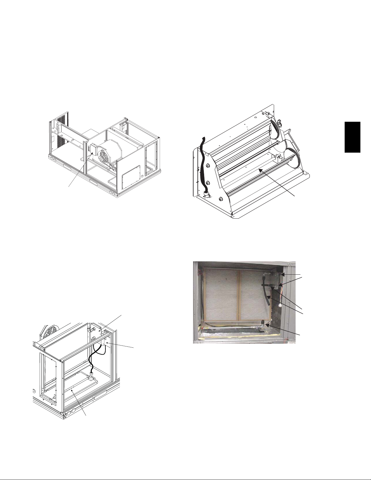
Smoke Detector Locations
Supply Air — The Supply Air smoke detector sensor is
located to the left of the unit’s indoor (supply) fan. See
Fig. 18. Access i s through the fan access panel. There is
no sampling tube used at this location. The sampling tube
inlet exte nds through the side plate of the fan housing
(into a high pressure area). The controller is located on a
bracket to the right of the return filter, accessed through
the lift--off filter panel.
Smoke Detector Sensor
C08245
Fig. 18 -- Typical Supply Air Smoke Detector Sensor
Location
Return Air without Economize r — The sampling tube is
located across the return air opening on the unit basepan.
See Fig. 19. The holes in the sampling tube fa ce
downward, into the return air stream. The sampling tube is
connected via tubing to the return a ir sensor that is
mounted on a bracket high on the partition between return
filter and controller location. (This sensor is shipped in a
flat--mounting location. Installation requires that this
sensor be relocated to its operating location and the tubing
to the sampling tube be connected. See installation steps
below.)
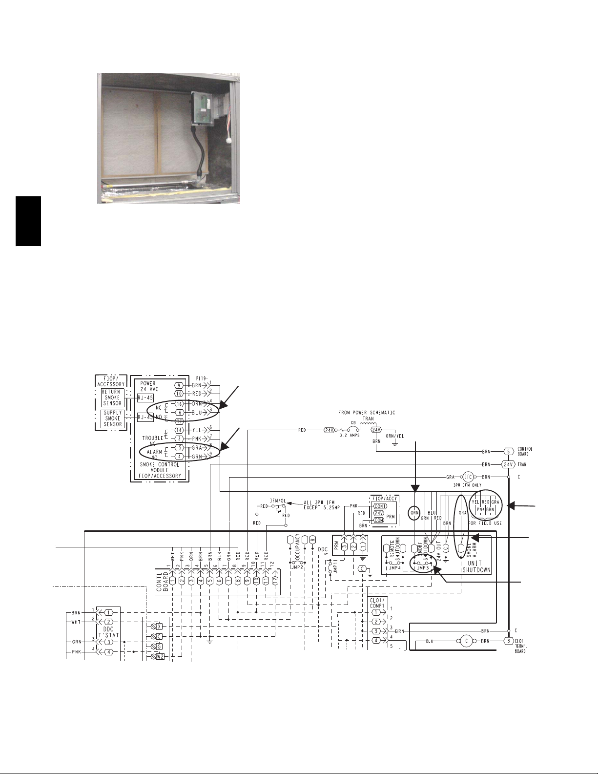
Return Air Detector module
(shipping position shown)*
Return Air with Economizer — The sampling tube is
inserted through the side plates of the economizer
housing, placing it across the return air opening on the
unit basepan. See Fig. 20. The holes in the sampling tube
face downward, into the return air stream. The sampling
tube is connected via tubing to the return air sensor that is
mounted on a bracket high on the partition between return
filter and controller location. (This sensor is shipped in a
flat--mounting location. Installation requires that this
sensor be relocated to its operating location and the tubing
to the sampling tube be connected. See installation steps
below.)
50TC
Return Air
Sampling Tube
C08129
Fig. 20 -- Return Air Sampling Tube Location
Completing Installation of Return Air Smoke
Sensor:
Screws
Flexible
Exhaust Tubes
Controller module
Return Air Detector Sampling Tube
*RA detector must be moved from shipping position to operating position by installer
C07307
Fig. 19 -- Typical Return Air Detector Location
Sample Tube
C08126
Fig. 21 -- Return Air Detector Shipping Position
1. Unscrew the two screws holding the Return Air
Sensor detector plate. See Fig 21. Save the screws.
2. Re move the Return Air Sensor and its detector plate.
3. Rotate the detector plate so the sensor is facing outwards and the sampling tube connection is on the bottom. See Fig 22.
4. Screw the sensor and det ector plate into its operating
position using screws from Step 1. Make sure the
sampling tube connection is on the bottom and the exhaust tube is on the top. See Fig 22.
5. Conne ct the flexible tube on the sam pling inlet t o the
sampling tube on the basepan.
15
Page 16
6. For units with an economizer, the sampling tube is integrated into the economizer housing but the connection of the flexible tubing to the sampling tube is the
same.
50TC
Fig. 22 -- Return Air Sensor Operating Position
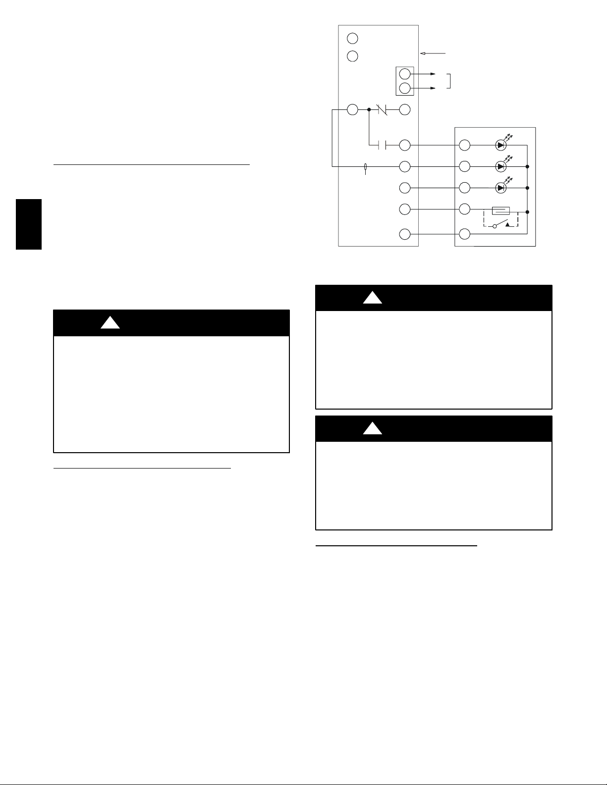
FIOP Smoke Detector Wiring and Response
All units: FIOP smoke detector is configured to
automatically shut down all unit operations when smoke
condition is detected. See Fig. 23, Smoke Detector
Wiring.
Highlight A: JMP 3 is fac tory--cut, transferring unit
control to smoke detector.
C08127
Highlight B: Smoke detector NC contact set will open on
smoke al arm condition, de--energizing the ORN
conductor.
Highlight C: 24--v power signal via ORN lead is removed
at Smoke Detector input on LCTB; all unit operations
cease immediately.
PremierLink Control: Unit operating functions (fan,
cooling and heating) are terminated as described above. In
addition:
Highlight D: On smoke alarm condition, the smoke
detector NO Alarm contact will close, supplying 24--v
power to GRA conductor.
Highlight E: GRA lead at Smoke Alarm input on LCTB
provides 24--v signal. This signal is conveyed to
PremierLink FIOP’s TB1 at terminal TB1--6 (BLU lead).
This signal initiates the FSD sequence by the PremierLink
control.
Using Remote Logic: Five conductors are provided for
field use (see Highlight F) for additional annunciation
functions.
Additional Application Data — Refer to Catalog No.
HKRNKA--1XA for discussions on additional control
features of these smoke detectors including multiple unit
coordination. See Fig. 23.
B
D
C
F
E
A
Fig. 23 -- Typical Smoke Detector System Wiring
16
C08246
Page 17

Sensor and Controller Tests
Sensor Alarm Test
The sensor alarm test checks a sensor’s ability to signal an
alarm state. This test requires that you use a field provided
SD-- MAG test magnet.
!
CAUTION
OPERATIONAL TEST HAZARD
Failure to follow t his caution may result in personnel
and authority concern.
This test places the duct detector into the alarm state.
Unless part of the test, disconnect all auxiliary
equipment from the controller before performing the
test. If the duct detector is connected to a fire alarm
system, notify the proper authorities before
performing the test.
Sensor Alarm Test Procedure
1. Hold the test magnet where indicated on the side of
the sensor housing for seven seconds.
2. Verify that the sensor’s Alarm LED turns on.
3. Re set the sensor by holding the test magnet against
the sensor housing for two seconds.
4. Verify that the sensor’s Alarm LED turns off.
!
CAUTION
OPERATIONAL TEST HAZARD
Failure to follow t his caution may result in personnel
and authority concern.
Pressing the controller’s test/re set switch for longer
than seven seconds will put the duct detector into the
alarm state and activate all automatic alarm responses.
Dirty Controller Test Procedure
1. Press the controller’s test/reset switch for two
seconds.
2. Verify that the controller’s Trouble LED flashes.
Dirty Sensor Test
The dirty sensor test provides an indication of the sensor’s
ability to compensate for gradual environmental changes.
A sensor that can no longer compensate for environmental
changes is considered 100% dirty and requires cleaning or
replacing. You must use a field provided SD--MAG test
magnet to initiate a sensor dirty test. The sensor’s Dirty
LED indicates the results of the dirty test as shown in
Table 2.
!
CAUTION
50TC
Controller Alarm Test
The controller alarm test checks the controller ’s ability to
initiate and indicate an alarm state.
!
CAUTION
OPERATIONAL TEST HAZARD
Failure to follow t his caution may result in personnel
and authority concern.
This test places the duct detector into the alarm state.
Disconnect all auxiliary equipment from the controller
before performing the test. If the duct detector is
connected to a fire alarm system, notify the proper
authorities before performing the test.
Controller Alarm Test Procedure
1. Press the controller’s test/reset switch for seven
seconds.
2. Verify that the controller’s Alarm LED turns on.
3. Re set the sensor by pressing the test/reset switch for
two seconds.
4. Verify that the controller’s Alarm LED turns off.
Dirty Controller Test
The dirty controller test checks the controller ’s ability to
initiate a dirty sensor test and indicate its results.
OPERATIONAL TEST HAZARD
Failure to follow t his caution may result in personnel
and authority concern.
Holding the test magnet agai nst the sensor housing for
more than seven seconds will put the duct detector
into the alarm state and activate all automatic alarm
responses.
Tabl e 2 – Di r ty L ED Te st
FLASHES DESCRIPTION
1 0---25% dirty. (Typical of a newly installed detector)
2 25---50% dirty
3 51---75% dirty
4 76---99% dirty
Dirty Sensor Test Procedure
1. Hold the test magnet where indicated on the side of
the sensor housing for two seconds.
2. Verify that the sensor’s Dirty LED flashes.
!
CAUTION
OPERATIONAL TEST HAZARD
Failure to follow t his caution may result in personnel
and authority concern.
Changing the dirty sensor test operation will put the
detector into the alarm state and activate all automatic
alarm responses. Before changing dirty sensor test
operation, disconnect all auxiliary equipment from the
controller and notify the proper authorities if
connected to a fire alarm system.
17
Page 18
Changing the Dirt Sensor Test
By default, sensor dirty test results are indicated by:
S The sensor’s Dirty LED flashing.
S The controller’s Trouble LED flashing.
S The controller’s supervision re lay contacts toggle.
The operation of a sensor’s dirty test can be changed so
that the controller ’s supervision relay is not used to
indicate test results. When two detectors a re connected to
a controller, sensor dirty test operation on both sensors
must be configured to operate in the same manner.
To Configure the Dirty Sensor Test
Operation
1. Hold the test magnet where indicated on the side of
the sensor housing until the sensor’s Alarm LED turns
on and its Dirty LED flashes twice (approximat ely 60
seconds).
2. Re set t he sensor by removing the test magnet then
50TC
holding it against the sensor housing again until the
sensor’s Alarm LED turns off (approximately 2
seconds).
Remote Station Test
The remote station a larm test checks a test/reset station’s
ability to initiate and indicate an alarm state.
12
1
3
S
upe
contacts [3]
W
ire must be
added by installer
rv
ision relay
TB3
1
2
14
1
3
19
15
2
20
Smoke Detector Controller
−
+
18 Vdc ( )
+
18 Vdc ( )
−
Auxiliary
equipment
5
4
1
3
2
SD-TRK4
Trouble
P
ower
Alarm
Reset/Test
Fig. 24 -- Remote Test/Reset Station Connections
!
CAUTION
C08247
!
CAUTION
OPERATIONAL TEST HAZARD
Failure to follow t his caution may result in personnel
and authority concern.
This test places the duct detector into the alarm state.
Unless part of the test, disconnect all auxiliary
equipment from the controller before performing the
test. If the duct detector is connected to a fire alarm
system, notify the proper authorities before
performing the test.
SD--TRK4 Remote Alarm Test Procedure
1. Turn the key switch to the RESET/TEST position for
seven seconds.
2. Verify that the test/reset station’s Alarm LED turns
on.
3. Re set the sensor by turning the key switch to the
RESET/TEST position for two seconds.
4. Verify that the test/reset station’s Alarm LED turns
off.
Remote Test/Reset Station Dirty Sensor Test
The test/reset station dirty sensor test checks the test/reset
station’s ability to initiate a sensor dirty test and indicate
the results. It must be wired to the controller as shown in
Fig. 24 and configured to operate the controller’s
supervision relay. For more information, see “Changing
sensor dirty test operation.”
OPERATIONAL TEST HAZARD
Failure to follow t his caution may result in personnel
and authority concern.
If the test/reset station’s key switch is left in the
RESET/TEST position for l onger than seven seconds,
the detector will automatically go into the alarm state
and activate all automatic alarm responses.
!
CAUTION
OPERATIONAL TEST HAZARD
Failure to follow t his caution may result in personnel
and authority concern.
Holding the test magnet to the target area for longer
than seven seconds will put the detector into the alarm
state and activate all automatic alarm responses.
Dirty Sensor Test Using an SD--TRK4
1. Turn the key switch to the RESET/TEST position for
two seconds.
2. Verify that t he test/rese t station’s Trouble LED
flashes.
DETECTOR CLEANING
Cleaning the Smoke Detector
Clean the duct smoke sensor when the Dirty LED is
flashing continuously or sooner i f conditions warrant.
18
Page 19
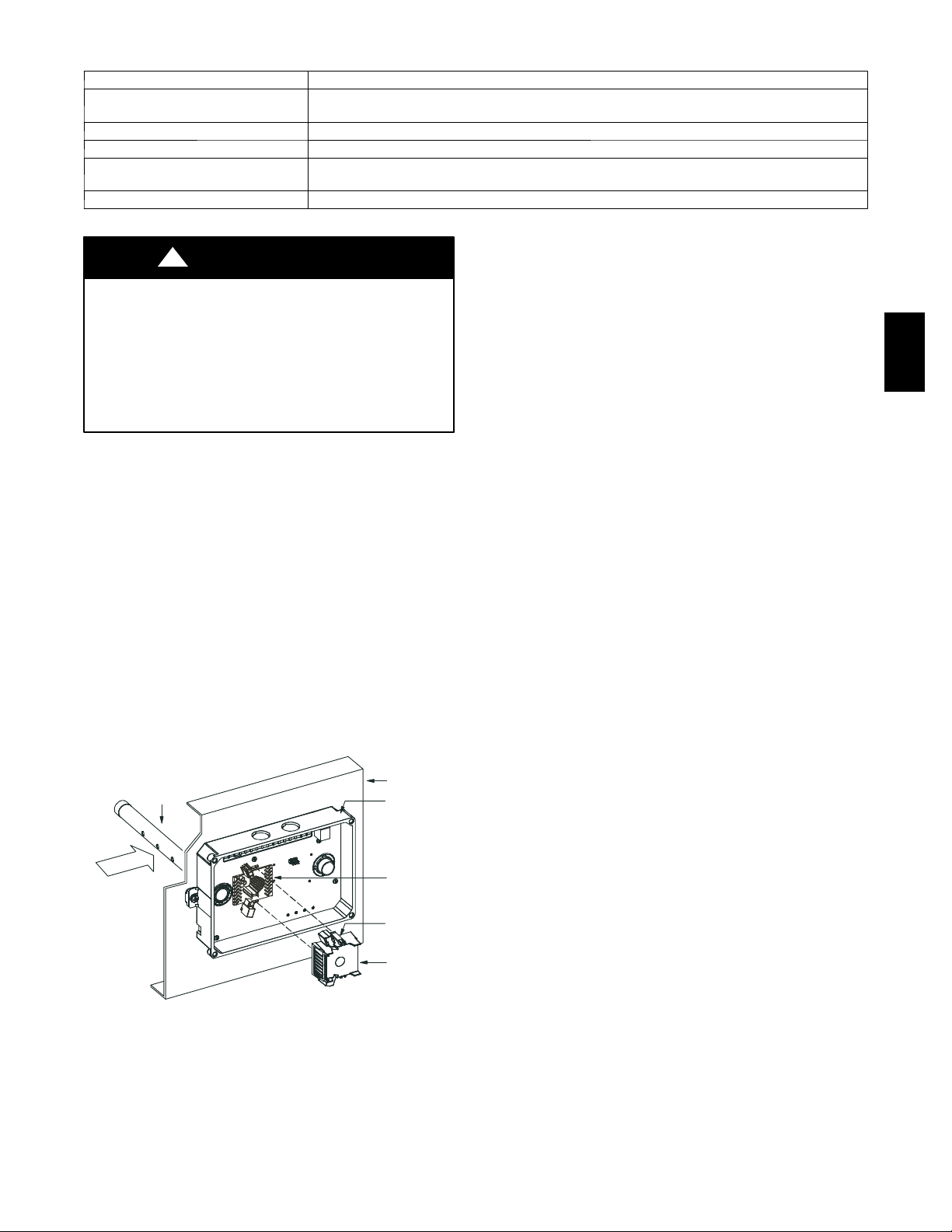
Table 3 – Detector Indicators
CONTROL OR INDICATOR DESCRIPTION
Magnetic test/reset switch Resets the sensor when it is in the alarm or trouble state. Activates or tests the sensor when it is in
Alarm LED Indicates the sensor is in the alarm state.
Troubl e LED Indicates the sensor is in the trouble state.
Dirty LED Indicates the amount of environmental compensation used by the sensor
Power LED Indicates the sensor is energized.
the normal state.
(flashing continuously = 100%)
!
CAUTION
OPERATIONAL TEST HAZARD
Failure to follow t his caution may result in personnel
and authority concern.
If the smoke detector is connected to a fire alarm
system, first notify the proper authorities that the
detector is undergoing maintenance then disable the
relevant circuit to avoid generating a false alarm.
1. Disconnect power from the duct detector then remove
the sensor’s cover. (See Fig. 25.)
2. Using a vacuum cleaner, clean compressed air, or a
soft bristle brush, remove loose dirt and debris from
inside the sensor housing and cover.
Use isopropyl alcohol and a l int--free cloth to remove
dirt and other contaminants from the gasket on the
sensor’s cover.
3. Squeeze the retainer clips on both sides of the optic
housing then lift the housing away from the printed
circuit board.
4. Gently remove dirt and debris from around the optic
plate and inside the optic housing.
5. Re place the optic housing and sensor cover.
6. Conne ct power to the duct detector then perform a
sensor alarm test.
Sampling
tube
Airow
HVAC duct
Sensor
housing
Optic
plate
Retainer
clip
Optic
housing
C07305
Fig. 25 -- Sensor Cleaning Diagram
INDICATORS
Normal State
The smoke detector operates in the norm al state in the
absence of any trouble conditions and when its sensing
chamber is free of smoke. In the normal state, the Power
LED on both the sensor and the controll er are on and all
other LEDs are off.
Alarm State
The smoke detector enters the alarm state when the
amount of smoke particulat e in the sensor’s sensing
chamber exceeds the alarm threshold value. (See Table 3.)
Upon entering the alarm state:
S The sensor’s Alarm LED and the controller’s Alarm LED
turn on.
S The contacts on the controller ’s two auxiliary relays
switch positions.
S The contacts on the controller’s alarm initiation relay
close.
S The controller’s remote alarm LED output is activated
(turned on).
S The controller ’s high impedance multiple fan shutdown
control line is pulled to ground Trouble state.
The SuperDuct duct smoke detector enters the trouble
state under the following conditions:
S A sensor’s cover is removed and 20 minut es pass before
it is properly secured.
S A sensor’s environmental compensation limit is reached
(100% dirty).
S A wiring fault between a sensor and the controller is
detected.
An internal sensor fault is detected upon entering the
trouble state:
S The contacts on the controller’s supervisory relay switch
positions. (See Fig. 26.)
S If a sensor trouble, the sensor ’s Trouble LED the
controller’s Trouble LED turn on.
S If 100% dirty, the sensor’s Dirty LE D turns on a nd the
controller’s Trouble LED flashes continuously.
50TC
19
Page 20
S If a wiring fault between a sensor and the controller, the
controller’s Trouble LED turns on but not the sensor’s.
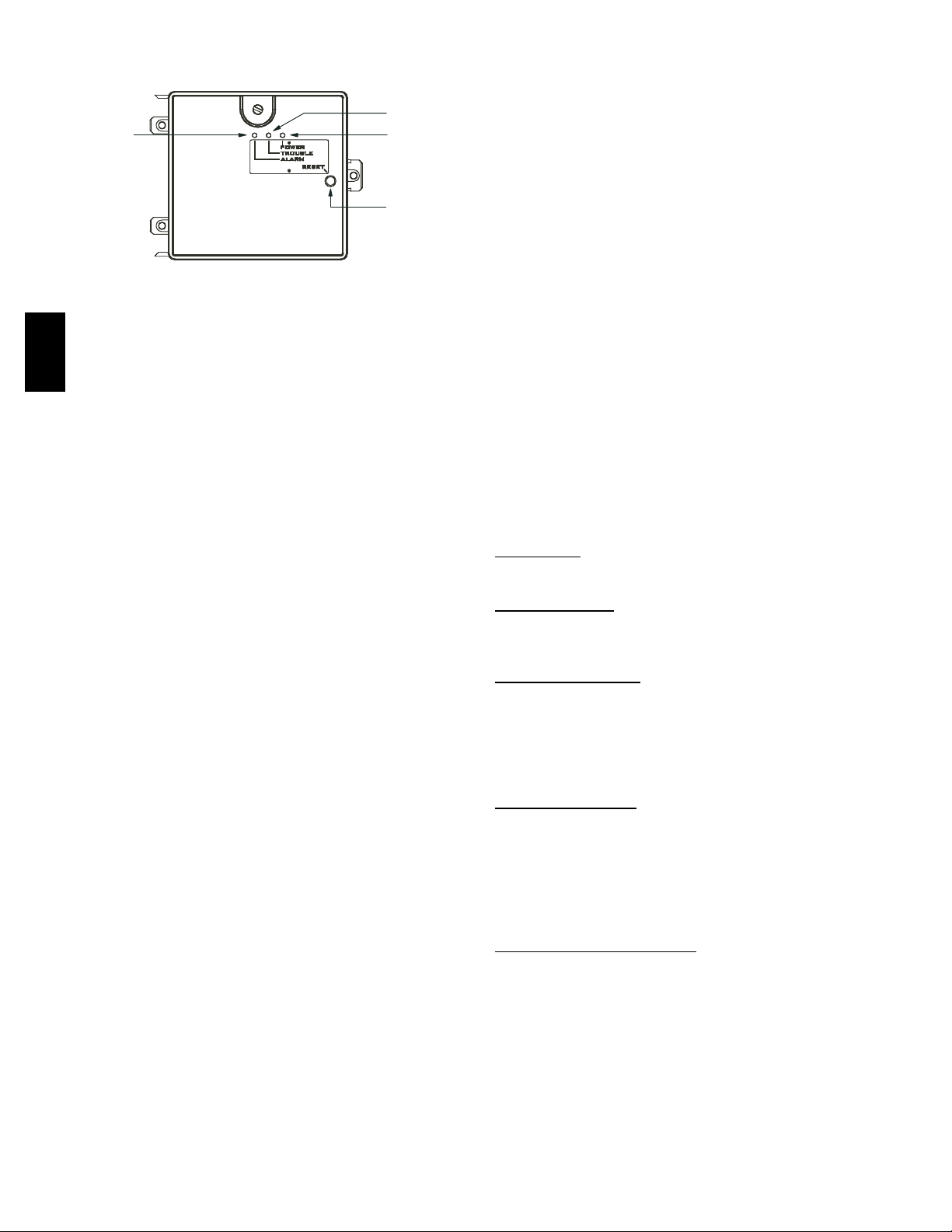
Alarm
Fig. 26 -- Controller Assembly
NOTE: All troubles are latched by the duct smoke
detector. The trouble condition must be cleared and then
the duct smoke detector must be reset in order to restore it
50TC
to the normal state.
Resetting Alarm and Trouble Condition Trips:
Manual reset is required to restore smoke detector systems
to Normal operation. For installations using two sensors,
the duct smoke detector does not differentiate which
sensor signals an alarm or trouble condition. Check each
sensor for Alarm or Trouble status (indicated by LED).
Clear the condition that has generated the trip at this
sensor. Then reset the sensor by pressing and holdi ng the
reset button (on the side) for 2 seconds. Verify that the
sensor’s Alarm and Trouble LEDs are now off. At the
controller, clear its Alarm or Trouble state by pressing and
holding the manual reset button (on the front cover) for 2
seconds. Verify that the controller’s Alarm and Trouble
LEDs are now off. Replace all panels.
Tro uble
Power
Test/reset
switch
C07298
2. Check the wiring between the sensor and the controller. If wiring is loose or missing, repair or replace as
required.
Controller’s Power LED is Off
1. Make sure the circuit supplying power to the controller is operational. If not, make sure JP2 and JP3 are
set correctly on the controller before applying power.
2. Verify that power is applied to the controller’s supply
input terminals. If power is not present, replace or repair wiring as required.
Remote Test/Reset Station’s Trouble LED Does
Not flash When Performing a Dirty Test, But the
Controller’s Trouble LED Does
1. Verify that the remote test/station is wired as shown
in Fig. 23. Repair or replace loose or missing wiring.
2. Configure the sensor dirty te st to activate the controller’s supervision relay. See “Changing sensor dirty
test operation.”
Sensor’s Trouble LED is On, But the Controller’s
Trouble LED is OFF
Remove JP1 on the controller.
PROTECTIVE DEVICES
Compressor Protection
Overcurrent
The compressor has internal linebreak motor protection.
Overtemperatur
The compressor has an internal protector to protect it
against excessively high discharge gas temperatures.
e
TROUBLESHOOTING
Controller’s Trouble LED is On
1. Check the Trouble LED on each sensor connected to
the controller. If a sensor’s Trouble LED is on, determine the cause and make the necessary repairs.
2. Check the wiring between the sensor and the controller. If wiring is loose or missing, repair or replace as
required.
Controller’s Trouble LED is Flashing
1. One or both of the sensors is 100% dirty.
2. Determine which Dirty LED is flashing then clean
that sensor assembly as described in the detector
cleaning section.
Sensor’s Trouble LED is On
1. Check the sensor’s Dirty LED. If it is flashing, the
sensor is dirty and must be cleaned.
2. Che ck the sensor’s cover. If it is loose or missing, secure the cover to the sensor housing.
3. Re place sensor assembly.
Sensor’s Power LED is Off
1. Che ck the controller’s Power LED. If it is off, determine why the controller does not ha ve power and
make the necessary repairs.
High Pressure
Switch
The system is provided with a high pressure switch
mounted on the discharge line. The switch is
stem--mounted and brazed into the discharge tube. Trip
setting is 630 psig +/-- 10 psig (4344 +/-- 69 kPa) when
hot. Reset is automatic at 505 psig (3482 kPa).
Low Pressure
Switch
The system is protected against a loss of charge and low
evaporator coil loading condition by a low pressure switch
located on the suction line near the compressor. The
switch is stem--mounted. Trip setting is 54 psig +/-- 5 psig
(372 +/-- 34 kPa). Reset is automatic at 117 +/-- 5 psig
(807 +/-- 34 kPa).
Evaporator Freeze Pr
otection
The system is protected against evaporator coil frosting
and low temperature conditions by a temperature switch
mounted on the evaporator coil hairpin. Trip setting is
30_F+/--5_F(--1_C+/--3_C). Reset is automatic at 45_F
(7_C).
Supply (Indoor) Fan Motor Protection
Disconnect and lockout power when servicing fan motor.
The standard supply fan motor is equipped with internal
overcurrent and overtem perature protection. Protection
devices reset automatically.
20
Page 21
The High Static option supply fan motor is equipped with
a pilot--circuit Thermix combination
overtemperature/overcurrent protection device. This
device resets automatically. Do not bypass this switch to
correct trouble. Determine the cause and correct it.
Condenser Fan Motor Protection
The condenser fan motor is internally protected against
overtemperature.
Relief Device
A soft solder joint at the suction service access port
provides pressure relief under abnormal temperature and
pressure conditions (i.e., fire in building). Protect this
joint during brazing operations near this joint.
Control Circuit, 24--V
DISCONNECT
MOUNTING
LOCATION
MAIN
CONTROL
BOX
BRACKET AND
CONDUIT
DRIP BOOT
EMT OR RIGID CONDUIT
(FIELD-SUPPLIED)
SINGLE POINT
BOX
MOUNTING
SCREW
CONTROL WIRE TERMINAL BLOCK
SINGLE
POINT BOX
HEATER
MODULE
(LOCATION 1)
CENTER
POST
HEATER
MODULE
(LOCATION 2)
MANUAL RESET
LIMIT SWITCH
Fig. 28 -- Typical Component Location
HEATER
COVERS
HEATER
MOUNTING
BRACKET
C08134
The control circuit is protected against overcurrent
conditions by a circuit breaker mounted on control
transformer TRAN. Reset is manual.
ELECTRIC HEATERS
50TC units may be equipped with field--installed
accessory electric heaters. The heaters a re modular in
design, with heater frames holding open coil resistance
wires strung through ceramic insulators, line--break limit
switches and a control contactor. One or two heater
modules may be used in a unit.
Heater modules are installed in the compartment below
the i ndoor (supply) fan outlet. Access is through the
indoor access panel. Heater modules slide into the
compartment on tracks along the bottom of the heater
opening. See Figs 27 -- 29.
DISCONNECT MOUNTING
LOCATION
UNIT BLOCK-OFF
PAN EL
OUTDOOR
ACCESS PANEL
Fig. 27 -- Typical Access Panel Location (3--6 Ton)
INDOOR
ACCESS
PAN EL
C08133
50TC
TRACK
FLANGE
C08135
Fig. 29 -- Typical Module Installation
Not all available heater modules may be used in every
unit. Use only those heater modules that are UL listed for
use in a specific size unit. Refer to the label on the unit
cabinet re approved heaters.
Unit heaters are marked with Heater Model Numbers. But
heaters are ordered as and shipped in cartons marked with
a corresponding heater Sales Package part number. See
Table 4 for correlation between heater Model Number and
Sales Package part number.
NOTE: The value in position 9 of the part number differs
between the sales package part number (value is 1) and a
bare heater model number (value is 0).
Bare Heater Model
Number
Heater Sales Package
PNO
Includes:
Bare Heater
Carton and packing
materials
Installation sheet
Table 4 – Heater Model Number
C R H E A T E R 0 0 1 A 0 0
C R H E A T E R 1 0 1 A 0 0
21
Page 22
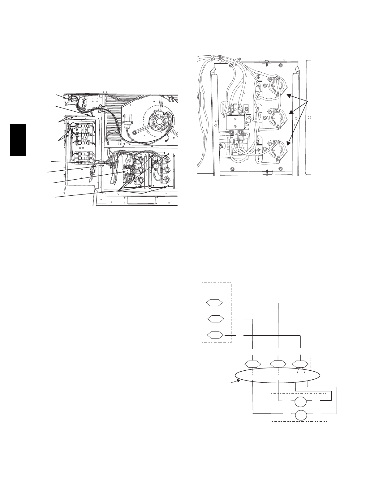
Single Point Boxes and Supplementary Fuses — When
the unit MOCP device value exceeds 60--A, unit--mounted
supplementary fuses are required for each heater circuit.
These fuses are included in accessory Single Point Boxes,
with power distribution and fuse blocks. The single point
box will be installed directly under the unit control box,
just to the left of the partition separating the indoor
section (with electric heaters) from the outdoor section.
The Single Point Box has a hinged access cover. See Fig
30.
50TC
CONTROL
BOX
BUSHING
SINGLE
POINT BOX
MOUNTING
SCREWS
DRIP BOOT
BRACKET
MOUNTING
SCREWS
POWER
WIRES
FOAM
BUSHING
HEATER
RELAYS
HEATER
MOUNTING
SCREWS
2
1
1
1
2
13
3
21
23
11
13
A
L
LIE
D
P
A
C
O
R
P
.
M
O
DE
L
N
O
.
O
D
ERI
A
L
N
O
.
2
2
.
2
ISTED
AIR
NDITIONING
1
2
3
UIP
ACCESS
346N
.
3
P
/ N
2-
5
6
1
REV
0
4
Fig. 30 -- Typical Single Point Installation
On 50TC units, all fuses are 60--A. Single point boxes
containing fuses for 208/230--V applications use UL Cl ass
RK5 250--V fuses (Bussman FRNR 60 or Shawmut TR
60R). Single point boxes for 460--V and 575--V
applications use UL Class T 600--V fuses (Bussman JJS
60 or Shawmut A6T 60). (Note that all heaters are
qualified for use with a 60--A fuse, regardless of actual
heater ampacity, so only 60--A fuses are necessary.)
Unit heater applications not requiring supplemental fuses
do not require a Single Point Box. Connect power supply
conductors to heater conductors and field--supplied base
unit power tap leads (see text below re: “Completing
Heater Installation”) below the unit’s main control box
using UL--approved connectors.
Safety Devices — Electric heater applications use a
combination of line--break/auto--reset limit switches and a
pilot--circuit/manual reset limit switch to protect the unit
against over--temperature situations.
Line--break/auto--reset limit switches are mounted on the
base plate of each heater module. See Fig. 31. These a re
accessed through the indoor access panel. Remove the
switch by removing two screws into the base plate and
extracting the existing switch.
Pilot-- c ircuit/manual reset limit switch is located in the
side plate of the indoor (supply) fan housing. See Fig. 28.
Completing Heater Installation
Field Power Connections — Field--supplied tap
conductors must be insta lled between the base unit’s field
power connection lugs and the splice connection between
field power supply conductors and the conductors to the
electric heater(s). Refer to unit wiring schematic. Use
C08136
copper wire only. Size these conduct ors based on the
MCA (Minimum Circuit Ampacity) value marked on the
50TC unit’s info plate for the base unit less electric heater
load. Use UL--approved pressure connectors
(field--supplied) for these splice joints.
Line-Break
Limit Switches
21
23
11
13
ALLIED P
A
MODE
L
NO.
OD
ERIAL
NO.
ISTED
AIR
NDITIONING
1
23
U
I
P
ACCESS
34
6
N
.
3
P
/ N
2
-
5610-4
RE
V
C08330
Fig. 31 -- Typical Location of Heater Limit Switches
(3--phase heater shown)
Low--Voltage Control Connections — Pull the
low--voltage control leads from the heater module(s) -VIO and BRN (two of each if two modules are installed;
identify for Module #1) -- to the 4--pole terminal board
TB4 located on the heater bulkhead to the left of Heater
#1. Connect the VIO lead from Heater #1 to terminal
TB4--1. Connect the VIO lead from Heater #2 to terminal
TB4--2. Connect both BRN leads to terminal TB4--3. See
Fig. 32.
LCTB
CONTL
BOARD
2
3
12
Field
VIO
ORN
BRN
BRN
BRN
BRN
ORN
13
TB4
VIO
VIO
2
VIO
Connections
Elec Htr
HR2
HR1
BRN
BRN
VIO
VIO
HR1: On Heater 1 in Position #1
HR2: On Heater 2 in Position #2 (if installed)
C08331
Fig. 32 -- Accessory Electric Heater Control
Connections
22
Page 23

Fig. 33 -- PremierLink Controller
50TC
C08199
PREMIERLINKT CONTROL
The PremierLink controller (see Fig. 33) is compatible
with Carrier Comfort Networkr (CCN) devices. This
control is designed to allow users the access and ability to
change factory--defined settings, thus expanding the
function of the standard unit control board. CCN service
access tools include System Pilot (TM), Touch Pilot (TM)
and Service Tool. (Standard tier display tools Navigatort
and Scrolling Marquee are not suitable for use with latest
PremierLink controller (Version 2.x).)
The PremierLink control is factory--mounted in the 50TC
unit’s main control box to the left of the LCTB. Factory
wiring is completed through harnesses connected to the
LVTB. Field connections are made at a 16--pole terminal
block (TB1) located on the bottom shelf of the unit
control box in front of the PremierLink controller The
factory--i nstalled PremierLink control includes the
supply--air temperature (SAT) sensor. The outdoor air
temperature (OAT) sensor is included in the
FIOP/accessory Economizer 2 package.
Refer to Fig. 33 for PremierLink connection locations.
NOTE: Refer to Form 33CS--58SI for complete
PremierLink configuration, operating sequences and
troubleshooting information. Have a copy of this manual
available at unit start--up.
The PremierLink controller requires the use of a Carrier
electronic thermostat or a CCN connection for time
broadcast to initiate its internal timeclock. This is
necessary for broadcast of time of day functions
(occupied/unoccupied).
NOTE: PremierLink controlle r is shipped in Sensor
mode. To be used with a thermostat, the PremierLink
controller must be configured to Thermostat mode. Refer
to PremierLink Configuration instructions for Operating
Mode.
Supply Air Temperature (SAT) Sensor — On
FIOP--equipped 50TC unit, the unit is supplied with a
supply--air tempe r ature (SAT) sensor (33ZCSENSAT).
This sensor is a tubular probe type, approx 6--inches (12.7
mm) in length. It is a nominal 10--k ohm thermistor. See
Table 15 for temperature--resistance characteristic.
The SAT is factory--wired. The SAT probe is wire--tied to
the supply--air opening (on the horizontal opening end) in
its shipping position. Remove the sensor for installati on.
Re--position the sensor in the flange of the supply -- a ir
opening or in the supply air duct (as required by local
codes). Drill or punch a 1/2--in. hol e in the flange or duct.
Use two field--supplied, self--drilling screws to secure the
sensor probe in a horizontal orientation. See Fig. 36.
SUPPLY AIR
TEMPERATURE
SENSOR
SUPPLY AIR
RETURN AIR
ROOF
CURB
C08200
Fig. 34 -- Typical Mounting Location for Supply Air
Temperature (SAT) Sensor on Small Rooftop Units
23
Page 24

50TC
C08249
24
Fig. 35 -- PremierLink Wiring Schematic
24
Page 25

Table 5 – Thermistor Resistance vs Temperature
Values for Space Temperature Sensor, Supply Air
Temperature Sensor, and Outdoor Air Temperature
Sensor
TEMP
(C)
--- 4 0 --- 4 0 335,651
--- 3 5 --- 3 1 242,195
--- 3 0 --- 2 2 176,683
--- 2 5 --- 1 3 130,243
--- 2 0 --- 4 96,974
--- 1 5 5 72,895
--- 1 0 14 55,298
--- 5 23 42,315
0 32 32,651
5 41 25,395
10 50 19,903
15 59 15,714
20 68 12,494
25 77 10,000
30 86 8,056
35 95 6,530
40 104 5,325
45 113 4,367
50 122 3,601
55 131 2,985
60 140 2,487
65 149 2,082
70 158 1,752
TEMP
(F)
RESISTANCE
(Ohms)
NOTE: The sensor must be mounted in the discharge
airstream downstream of the cooling coil and any heating
devices. Be sure the probe tip does not come in contact
with any of the unit’s heater surfaces.
Outdoor Air Temperature (OAT) Sensor — The OAT is
factory--m ounted in the Economizer 2 (FIOP or
accessory). It is a nominal 10k ohm thermistor attached to
an eyelet mounting ring. See Table 5 for
temperature-- resistance characteristic.
Field connections — Field connections for accessory
sensor and input devices are made at the 16--pole terminal
block (TB1) l ocated on the control box bottom shelf in
front of the PremierLink control. Some input devices also
require a 24--vac signal source; connect at LCTB terminal
R at “THERMOSTAT” connection strip for this signal
source. See connections figures on following pages for
field connection locations (and for continued connections
at the PremierLink board inputs).
Table 7 provides a summary of field connections for units
equipped with Space Sensor. Table 8 provides a summary
of field connections for units equippe d with Space
Thermostat.
Space Sensors -- The PremierLink controller is
factory--shippe d configured for Space Sensor Mode. A
Carrier T--55 or T--56 space sensor must be used. T--55
space temperature sensor provides a signal of space
temperature to the PremierLink cont rol. T--56 provides
same space temperature signal plus it allows for
adjustment of space temperature setpoints from the face of
the sensor by the occupants. See Table 5 for temperature
versus resistance characteristic on the space sensors.
Connect T --55 -- See Fig. 36 for typical T--55 internal
connections. Connect the T--55 SEN terminals to TB1
terminals 1 and 3 (see Fig. 37).
2
SW1
3
45
SEN
61
RED(+)
WHT(GND)
BLK(-)
BRN (GND)
BLU (SPT)
CCN COM
SENSOR WIRING
50TC
Economizer 2 — The PremierLink control is used with
Economizer 2 (option or accessory) for outdoor air
management. The damper position is controlled directly
by the PremierLink control; Economizer 2 has no internal
logic device.
Outdoor air management functions ca n be enhanced with
field--installation of these accessory control devices:
Enthalpy control (outdoor air or differentia l sensors)
Space CO2 sensor
Outdoor air CO2 sensor
Refer to Table 6 for accessory part numbers
Fig. 36 -- T--55 Space Temperature Sensor Wiring
TB1 PL
SEN J6-7
SEN
1
3
Fig. 37 -- PremierLink T55 Sensor
25
C08201
J6-6
C08212
Page 26

Table 6 – PremierLink Sensor Usage
OUTDOOR AIR
APPLICATION
Differential Dry Bulb
Temp e rat u re w ith
PremierLink (PremierLink
r e q u i r e s 4 --- 2 0 m A
Actuator)
Single Enthalpy with
PremierLink (PremierLink
r e q u i r e s 4 --- 2 0 m A
Actuator)
Differential Enthalpy with
PremierLink (PremierLink
r e q u i r e s 4 --- 2 0 m A
Actuator)
NOTES:
CO2 Sensors (Optional):
33ZCSENCO2 --- Room sensor (adjustable). Aspirator box is required for duct mounting of the sensor.
33ZCASPC02 --- Aspirator box used for duct---mounted CO2 room sensor.
50TC
33ZCT55CO2 --- Space temperature and CO2 room sensor with override.
33ZCT56C02 --- Space temperature and CO2 room sensor with override and setpoint.
TEMPERATURE
SENSOR
I n c l u d e d ---
CRTEMPSN001A00
I n c l u d e d ---
Not Used
I n c l u d e d ---
Not Used
RETURN AIR
TEMPERATURE
SENSOR
R e q u i r e d ---
33ZCT55SPT
or equivalent
---
---
OUTDOOR AIR
ENTHALPY SENSOR
--- ---
R e q u i r e s ---
HH57AC077
or equivalent
R e q u i r e s ---
HH57AC077
or equivalent
RETURN AIR
ENTHALPY SENSOR
---
R e q u i r e s --HH57AC078
or equivalent
26
Page 27

Table 7 – Space Sensor Mode
TB1 TERMINAL FIELD CONNECTION INPUT SIGNAL
1 T 5 5 --- S E N / T56 --- S E N Analog (10k thermistor)
2 RMTOCC Discrete, 24VAC
3 T 5 5 --- S E N / T56 --- S E N Analog (10k thermistor)
4 CMPSAFE Discrete, 24VAC
5 T 5 6 --- S E T Analog (10k thermistor)
6 FSD Discrete, 24VAC
7 LOOP--- PWR Analog, 24VDC
8 SPS Discrete, 24VAC
9 I A Q --- S E N An alog, 4 --- 2 0 m A
10 FIL TER Discrete, 24VAC
11 I A Q --- C OM/O A Q --- C O M/RH --- C O M A n a l o g , 4 --- 2 0 m A
12 CCN + (RED) Digital,,5VDC
13 O A Q --- SEN/ R H --- S E N A n a l o g , 4 --- 2 0 m A
14 CCN Gnd (WHT) Digital, 5VDC
15 AUX OUT(Power Exhaust) (Output)Discrete 24V AC
16 CCN --- (BLK) Digital, 5VDC
LEGEND:
T55 --- Space Temperature Sensor
T56 --- Space Temperature Sensor
CCN --- Carrier Comfort Network (communication bus)
CMPSAFE --- Compressor Safety
FILTER --- Dirty Filter Switch
F S D --- F i r e S h u t d o w n
IAQ --- Indoor Air Quality (CO2)
OAQ --- Outdoor Air Quality (CO2)
RH --- Relative Humidity
SFS --- Supply F an Status
Table 8 – Thermostat Mode
TB1 TERMINAL FIELD CONNECTION INPUT SIGNAL
1 RAT SEN Analog (10k thermistor)
2 G Discrete, 24VAC
3 RAT SEN Analog (10k thermistor)
4 Y1 Discrete, 24VAC
5
6 Y2 Discrete, 24VAC
7 LOOP--- PWR Analog, 24VDC
8 W1 Discrete, 24VAC
9 I A Q --- S E N A n a l o g , 4 --- 2 0 m A
10 W2 Discrete, 24VAC
11 I A Q --- C O M / O A Q --- C O M / R H --- C O M A n a l o g , 4 --- 2 0 m A
12 CCN + (RED) Digital, 5VDC
13 O A Q --- SEN/R H --- S E N A n a l o g , 4 --- 20mA
14 CCN Gnd (WHT) Digital, 5VDC
15 AUX OUT (Power Exhaust) (Output) Discrete 24V AC
16 CCN --- (BLK) Digital, 5VDC
LEGEND:
CCN --- Carrier Comfort Network (communication bus)
G --- T h e r mo s t a t Fan
IAQ --- Indoor Air Quality (CO2)
OAQ --- Outdoor Air Quality (CO2)
RAT --- Return Air Temperature
RH --- Relative Humidity
W1 --- Thermostat Heat Stage 1
W2 --- Thermostat Heat Stage 2
Y1 --- Thermostat Cool Stage 1
Y2 --- Thermostat Cool Stage 2
50TC
27
Page 28

Connect T--56 -- See Fig. 38 for T--56 internal
connections. Install a jumper between SEN and SET
terminals as illustrated. Connect T--56 terminals to TB1
terminals 1, 3 and 5 (see Fig. 39).
2
SW1
3
45
SEN
61
RED(+)
WHT(GND)
BLK(-)
SET
BLK
(T56)
BRN (GND)
BLU (SPT)
CCN COM
SENSOR WIRING
JUMPER
TERMINALS
AS SHOWN
50TC
PremierLink Configuration screen for Operating Mode.
Default setting is Sensor Mode (value 1). Change the
value to 0 to reconfigure the controller for Thermostat
Mode.
When the PremierLink is configured for Thermostat
Mode, these functions are not available: Fire Shutdown
(FSD), Remote Occupied (RMTOCC), Compressor Safety
(CMPSAFE), Supply Fan Status (SFS), and Filter Pressure
Switch (FILTER).
Economizer controls —
Outdoor Air Enthalpy Control (PNO HH57AC077) --
The enthalpy control (HH57AC077) is available as a
field--installed accessory to be used with the EconoMi$er2
damper system. The outdoor air enthalpy sensor is part of
the enthalpy control. (The separate field--installed
accessory return air enthalpy sensor (HH57AC078) is
required for differential enthalpy control. See below.)
Cool Warm
C08202
Fig. 38 -- T--56 Internal Connections
TB1 PL
SEN J6-7
SEN
Jumper
SET
SET
1
TB1
3
5
PL
J6-6
J6-5
C08213
Fig. 39 -- PremierLink T56 Sensor
Connect Thermostat — A 7--wire thermostat connection
requires a 24--v power source and a common connection.
Use the R and C terminals on the LCTB’s THERMOSTAT
connection strip for these. Connect the thermostat’s Y1,
Y2, W1, W2 and G terminals to PremierLink TB1 as
shown in Fig. 40.
If the 50TC unit is equipped with factory--installed smoke
detector(s), disconnect the factory BLU lead at TB1--6
(Y2) before connecting the thermostat. Identify the BLU
lead originating at LCTB DDC--1; disconnect at TB1--6
and tape off. Confirm that the second BLU lead at TB1--6
remains connected to PremierLink J4--8.
If the 50TC unit has an economizer system and
free--cool ing operation is required, a sensor representing
Return Air Temperature must also be connected
(field--supplied and installed). This sensor may be a T--55
Space Sensor (see Fig. 36) insta lled in the space or in the
return duct, or it may be sensor PNO 33ZCSENSAT,
installed in the return duct. Connect this sensor to TB1 --1
and TB1--3 per Fig. 37. Temperature--resistance
characteristi c is found in Table 5.
Locate the enthalpy control in the economizer hood.
Locate two GRA leads in the factory harness and connect
these leads to enthalpy control sensors 2 and 3. See Fig.
41. Connect the enthalpy control power input terminals to
economizer actuator power leads RED (connect to TR)
and BLK (connect to TR).
SPACE
THERMOSTAT
R
G J4-12
Y1
Y2
W1
W2
C
LCTB
THERMOSTAT
R
TB1
2
4
6
8
10
LCTB
C
PL
J4-10
J4-8
J4-6
J4-4
THERMOSTAT
C08119
Fig. 40 -- Space Thermostat Connections
Enthalpy
Switch
2
GRA
3
GRA
LCTB
ECON
6
7
Factory Wiring Harness
C08218
Fig. 41 -- Enthalpy Switch (HH57AC077) Connections
Configure the unit for Thermostat Mode — Connect to the
CCN bus using a CCN service tool and navigate to
The outdoor enthalpy changeover setpoint is set at the
enthalpy controller.
28
Page 29

The enthalpy control receives the outdoor air enthalpy
from the outdoor air enthalpy sensor and provides a dry
contact switch input to the PremierLink controller. A
closed contact indicates that outside air is preferred to the
return air. An open contact indicates that the economizer
should remain a t minimum position.
levels. This information is used to monitor IAQ levels.
Several types of sensors are available, for wall mounting
in the space or in return duct, with and without LCD
display, and in combination with space temperature
sensors. Sensors use infrared technology to measure the
levels of CO2 present in the space air.
Differential Enthalpy Control — Differential enthalpy
control is provide d by sensing and comparing the outside
air and return air enthalpy conditions. Install the outdoor
air enthalpy control as described above. Add and install a
return air enthalpy sensor.
Return Air Enthalpy Sensor — Mount the return--air
enthalpy sensor (HH57AC078) in the return--air duct. The
return air sensor is wired to the enthalpy controller
(HH57AC077). See Fig. 42.
ENTHALPY CONTROLLER
B
TR TR1
C
A
D
SO
SR
2
LED
NOTES:
1. Remove factory-installed jumper across SR and + before connecting
wires from return air sensor.
2. Switches shown in high outdoor air enthalpy state. Terminals 2 and 3
close on low outdoor air enthalpy relative to indoor air enthalpy.
3. Remove sensor mounted on back of control and locate in outside airstream.
RED
BRN
BLK
+
+
3
1
RED
GRAY/ORN
GRAY/RED
WIRE HARNESS
IN UNIT
(OUTDOOR
S
AIR
+
ENTHALPY
SENSOR)
S
(RETURN AIR
ENTHALPY
+
SENSOR)
The CO2 sensors are all factory set for a range of 0 to
2000 ppm and a linear mA output of 4 t o 20. Refer to the
instructions supplied with the CO2 sensor for electrical
requirements and term inal locations. See Fig. 43 for
typical CO2 sensor wiring schematic.
+
0-10VDC
-
SIG COM (J4-6)
+
4-20mA (J4-5)
ALARM
NC
COM
RELAY
}
CONTACTS
NO
24 VAC
HG
OR
+
-
24 VDC
2
1
5
1
4
32
7
6
8
50TC
C06019
Fig. 42 -- Outside and Return Air Enthalpy Sensor
Wiring
To wire the return air enthalpy sensor, perform the
following:
1. Use a 2--conduc tor, 18 or 20 AWG, twisted pair cable
to connect the return air enthalpy sensor to the enthalpy controller.
2. At the enthalpy control remove the factory--installed
resistor from the (SR) and (+) terminals.
3. Connect the field--supplied RED wire to (+) spade
connector on the return air enthalpy sensor and the
(SR+) terminal on the enthalpy control ler. Connect
the BLK wire to (S) spade connector on the return air
enthalpy sensor and the (SR) terminal on the enthalpy
controller.
NOTE: The enthalpy control must be set to the “D”
setting for differential enthalpy control to work properly.
The enthalpy control receives the indoor and return
enthalpy from the outdoor and return air enthalpy sensors
and provides a dry conta ct switch input to the
PremierLink controller. A closed contact indicates that
outside air is preferred to the return air. An open contact
indicates that the economizer should remain at minimum
position.
Indoor Air Quality (CO2 sensor) — The indoor air quality
sensor accessory monitors space carbon dioxide (CO2)
C07134
Fig. 43 -- Indoor/Outdoor Air Quality (CO2) Sensor
(33ZCSENCO2) -- Typical Wiring Diagram
To accurately monitor the quality of the air in the
conditioned air space, locate the sensor near a return--air
grille (if present) so it senses the concentration of CO2
leaving the space. The sensor should be mounted in a
location to avoid direct breath contact.
Do not mount the IAQ sensor in drafty areas such as near
supply ducts, open windows, fans, or over heat sources.
Allow at least 3 ft (0.9 m) between the sensor and any
corner. Avoid mounting the sensor where it is influenced
by the supply air; the sensor gives inaccurate readings if
the supply air is blown directly onto the sensor or if the
supply air doe s not have a chance to mix with the room air
before it is drawn into the return a irstream.
Wiring the Indoor Air Quality Sensor —
For each sensor, use two 2--conductor 18 AWG (American
Wire Gage) twisted--pair cables (unshielded) to connect
the separate isolated 24 vac power source to the sensor
and to connect the sensor to the control board terminals.
To connect the sensor to the control, identify the positive
(4 to 20 mA) and ground (SIG COM) terminals on the
sensor. See Fig. 43. Connect the 4--20 mA terminal to
terminal TB1--9 and connect the SIG COM terminal to
terminal TB1--7. See Fig. 44.
29
Page 30

IAQ Sensor
SEN J5-5
COM
24 VAC
TB1
9
TB1
7
PL
J5-6
C08274
Fig. 44 -- Indoor CO2 Sensor (33ZCSENCO2) Connec-
tions
Refer to Form 33CS--58SI, PremierLink Insta llation,
Start--up, and Configuration Instructions, for detailed
configuration information.
Smoke Detector/Fire Shutdown (FSD) — This function is
available only when PremierLink is configured for
(Space) Sensor Mode. The unit is factory--wired for
PremierLink FSD operation when PremierLink is
factory--i nstalled.
Refer to Form 33CS--58SI, PremierLink Insta llation,
Start--up, and Configuration Instructions, for detailed
configuration information
Outdoor Air Quality Sensor (PNO 33ZCSENCO2 plus
weatherproof enclosure) — The outdoor air CO2 sensor is
designed to m onitor carbon dioxide (CO2) levels in the
outside ventilation air and interface with the ventilation
damper in an HVAC system. The OAQ sensor is packaged
50TC
with an outdoor cove r. See Fig. 45. The outdoor air CO2
sensor must be located in the economizer outside air hood.
COVER REMOVED SIDE VIEW
Fig. 45 -- Outdoor Air Quality Sensor Cover
C07135
On 50TC units equipped with factory--installed Smoke
Detector(s), the smoke detector controller implements the
unit shutdown through its NC contact set connected to the
unit’s LCTB input. The FSD func tion is initiated via the
smoke detector’s Alarm NO contact set. The PremierLink
communicates the smoke detector’s tripped status to the
CCN building control. See Fig. 23 for unit smoke detector
wiring.
Alarm state is reset when the smoke detector alarm
condition is cleared and reset at the smoke detector in the
unit.
If the PremierLink mode ha s been changed to Thermostat,
disconnect the BLU lead (from LCTB DDC--1) at TB1--6
(Y2) and tape off before connecting the thermostat to
TB1.
Filter Status Switch — This function is available only
when PremierLink is configured for (Space) Sensor Mode.
PremierLink control can monitor return filter status in two
ways: By monitoring a field--supplied/installed filter
pressure switch or via supply fan runtime hours.
Using switch input: Install the dirty filter pressure switch
according to switch manufacturer’s instructions, to
measure pressure drop across the unit’s return filters.
Connect one side of the switch’s NO contact set to
LCTB’s THERMOSTAT--R terminal. Connect the other
side of the NO contact set to TB1--10. Setpoint for Dirty
Filter is set at the switch. See Fig. 47.
Wiring the Outdoor Air CO2 Sensor — A dedicated
power supply is required for this sensor. A two--wire cable
is required to wire the dedicated power supply for the
sensor. The two wires should be connected to the power
supply and terminals 1 and 2.
To connect the sensor to the control, identify the positive
(4 to 20 mA) and ground (SIG COM) terminals on the
OAQ sensor. See Fig. 43. Connect the 4 to 20 mA
terminal to 50TC’s terminal TB1--11. Connect the SIG
COM terminal to 50TC’s terminal TB1-- 13. See Fig. 461.
OAQ Sensor/RH Sensor
SEN J5-2
COM
24 VAC
TB1
13
TB1
11
PL
J5-3
C08275
Fig. 46 -- Outdoor CO2 Sensor Connections
Filter Switch (NO, close on rising pressure (high drop))
LCTB
Thermostat
R
TB1
10
PL
J4-4
C08216
Fig. 47 -- PremierLink Filter Switch Connection
When the filter switch’s NO contact set closes as filter
pressure drop increases (indicating dirt--laden filters), the
input signal to PremierLink causes the filter status point to
read “DIRTY”.
Using Filter Timer Hours: Refer to Form 33CS--58SI for
instructions on using the PremierLink Configuration
screens and on unit alarm sequence.
Supply Fan Status Switch — The PremierLink control can
monitor supply fan operation through a
field--supplied/installed differential pressure switch. This
30
Page 31

sequence will prevent (or interrupt) operation of unit
cooling, heating and economizer functions until the
pressure switch contacts are c losed indicating proper
supply fan operation.
Install the differential pressure switch in the supply fan
section according to switch manufacturer’s instructions.
Arrange the switch c ontact to be open on no flow and to
close as pressure rises indicating fan operation.
Connect one side of the switch’s NO contact set to
LCTB’s THERMOSTAT--R terminal. Connect the other
side of the NO contact set to TB1--8. Setpoint for Supply
Fan Status is set at the switch. See Fig. 48
Fan (Pressure) Switch (NO, close on rise in pressure)
LCTB
Thermostat
R
TB1
8
PL
J4-6
C08118
Fig. 48 -- PremierLink Wiring Fan Pressure Switch
Connection
Remote Occupied Switch — The PremierLink control
permits a remote timeclock to override the control’s
on--board occupancy schedule and place the unit into
Occupied mode. This function may also provide a “Door
Switch” time delay function that will terminate cooling
and heating functions after a 2--20 minute delay.
Connect one side of the NO contact set on the timeclock
to LCTB’s THERMOSTAT--R terminal. Connect the other
side of the timeclock contact to the unit’s TB1--2 terminal.
Remote Occupied
Time Clock
LCTB
Thermostat
R
TB1
2
PL
J4-12
C08214
Fig. 49 -- PremierLink Wiring Remote Occupied
Refer to Form 33CS--58SI for additional information on
configuring the PremierLink control for Door Switch
timer function.
Power Exhaust (output) -- Connect the accessory Power
Exhaust contactor coils(s) per Fig. 50.
Power Exhaust
PEC
TAN
TB1
15
PL
J8-3
LCTB
THERMOSTAT
GRA
C
C08120
Fig. 50 -- PremierLink Power Exhaust Output
Connection
Space Relative Humidity Sensor — The RH sensor is not
used with 50TC models at this time.
CCN Communication Bus — The PremierLink controller
connects to the bus in a daisy chain arrangement.
Negative pins on each component must be connected to
respective negative pins, and likewise, positive pins on
each component must be connected to respective positive
pins. The controller signal pins must be wired to the signal
ground pins. Wiring connections for CCN must be ma de
at the 3--pin plug.
At any baud (9600, 19200, 38400 baud), the number of
controllers is limited to 239 devices maximum. Bus length
may not exceed 4000 ft, with no more than 60 total
devices on any 1000--ft section. Optically isolated RS--485
repeaters are required every 1000 ft.
NOTE: Carrier device default is 9600 band.
COMMUNICATION BUS WIRE SPECIFICATIONS —
The CCN Communication Bus wiring is fi eld--supplied
and field--installed. It consists of shielded 3--conductor
cable with drain (ground) wire. The cable selec ted must
be identical to the CCN Communication Bus wire used for
the entire network.
See Table 9 for recommended cable.
Table 9 – Recommended Cables
MANUFACTURER CABLE PART NO.
Alpha 2413 or 5463
American A22503
Belden 8772
Columbia 02525
NOTE: Conductors and drain wire must be at l east 20
AWG, stranded, and tinned copper. Individual conductors
must be insulated with PVC, PVC/nylon, vinyl, Teflon, or
polyethylene. An aluminum/polyester 100% foil shield
and an outer jacket of PVC, PVC/nylon, chrome vinyl, or
Teflon with a minimum operating temperature range of
--20 C to 60 C is required. Do not run communication wire
in the same conduit as or next to any AC voltage wiring.
The communication bus shields must be tied together at
each system element. If the communication bus is entirely
within one building, the resulting continuous shield must
be connected to ground at only one single point. If the
communication bus cable exits from one building and
enters another building, the shields must be connected to
the grounds at a lightning suppressor in each building (one
point only).
Connecting CCN bus:
NOTE: When connecting the communication bus cable,
a color code system for the entire network is
recommended to simplify installation and checkout. See
Table 10 for the recommended color code.
Table 10 – Color Code Recommendations
SIGNAL TYPE
+ Red 1
Ground White 2
--- Black 3
CCN BUS WIRE
COLOR
CCN PLUG PIN
NUMBER
Connect the CCN (+) lead (typically RED) to the unit’s
TB1--12 ter minal. Connect the CCN (ground) l ead
31
50TC
Page 32

(typically WHT) to the unit’s TB1--14 terminal. Connect
A
the CCN (--) lead (typically BLK) to the unit’s TB1--16
terminal. See Fig. 51.
CCN Bus
TB1
+ (RED)
12
TB1
GND (WHT)
14
TB1
– (BLK)
16
Fig. 51 -- PremierLink CCN Bus Connections
ECONOMIZER SYSTEMS
50TC
The 50TC units may be equipped with a factory--installed
or accessory (field--installed) economizer system. Two
types are available: with a logic control system
(EconoMi$er IV) and without a control system
(EconoMi$er2, for use with external control systems such
as PremierLink). See Fig. 52 and 53 for component
locations on each type. See Fig. 54 and 55 for economizer
section wiring diagrams.
Both economizers use direct--drive damper actuators.
PL
J2-1
J2-2
J2-3
C08276
ECONOMI$ER IV
CONTROLLER
WIRING
HARNESS
CTUATOR
OUTSIDE AIR
TEMPERATURE SENSOR
LOW AMBIENT
SENSOR
Fig. 52 -- EconoMi$er IV Component Locations
OUTDOOR
AIR HOOD
ECONOMI$ER2
PLUG
BAROMETRIC
RELIEF
DAMPER
HOOD
SHIPPING
BRACKET
GEAR DRIVEN
DAMPER
Fig. 53 -- EconoMi$er2 Component Locations
C06021
C06022
DCV— Demand Controlled Ventilation
IAQ — Indoor Air Quality
LA — Low Ambient Lockout Device
OAT — Outdoor-Air Temperature
POT— Potentiometer
RAT— Return-Air Temperature
LEGEND
8
7
Potentiometer Defaults Settings:
Power Exhaust Middle
Minimum Pos. Fully Closed
DCV Max. Middle
DCV Set Middle
Enthalpy C Setting
Fig. 54 -- EconoMi$er IV Wiring
FOR OCCUPANCY CONTROL
REPLACE JUMPER WITH
FIELD-SUPPLIED TIME CLOCK
NOTES:
1. 620 ohm, 1 watt 5% resistor should be removed only when using differential
enthalpy or dry bulb.
2. If a separate field-supplied 24 v transformer is used for the IAQ sensor power
supply, it cannot have the secondary of the transformer grounded.
3. For field-installed remote minimum position POT, remove black wire jumper
between P and P1 and set c ontrol minimum position POT to the minimum
position.
C06028
32
Page 33

BLACK
BLUE
500 OHM
RESISTOR
VIOLET
NOTE 1
RUN
NOTE 3
50HJ540573
ACTUATOR
ASSEMBLY
DIRECT DRIVE
ACTUATOR
NOTES:
1. Switch on actuator must be in run position for economizer to operate.
2. PremierLink™ control requires that the standard 50HJ540569 outside-air sensor be replaced by either the CROASENR001A00 dry bulb sen
sor or HH57A077 enthalpy sensor.
3. 50HJ540573 actuator consists of the 50HJ540567 actuator and a harness with 500-ohm resistor.
OAT SENSOR
4-20mA SIGNAL
PINK
YELLOW
WHITE
4
TRANSFORMER
GROUND
3
5
2
8
6
7
RED
ECONOMISER2 PLUG
10
12
24 VAC
1
11
9
4-20 mA
TO J9 ON
PremierLink
BOARD
C08310
Fig. 55 -- EconoMi$er2 with 4 to 20 mA Control Wiring
50TC
Table 11 – EconoMi$er IV Input/Output Logic
INPUTS OUTPUTS
Demand Control
Ventilation (DCV)
Below set
(DCV LED Off)
Above set
(DCV LED On)
(Free Cooling LED Off)
(Free Cooling LED On)
(Free Cooling LED Off)
(Free Cooling LED On)
Enthalpy*
Outdoor Return
High
Low
High
Low
Low
High
Low
High
Y1 Y2
On On On On
Off Off Off Off
On On On Off
On Off Off Off
Off Off Off Off Minimum position Closed
On On On On
On Off On Off
Off Off Off Off
On On On Off
Off Off Off Off
* For single enthalpy control, the module compares outdoor enthalpy to the ABCD setpoint.
† Power at N terminal determines Occupied/Unoccupied setting: 24 vac (Occupied), no power (Unoccupied).
** Modulation is based on the supply-air sensor signal.
†† Modulation is based on the DCV signal.
*** Modulation is based on the greater of DCV and supply-air sensor signals, between minimum position and either maximum position (DCV)
or fully open (supply-air signal).
††† Modulation is based on the greater of DCV and supply-air sensor signals, between closed and either maximum position (DCV) or fully
open (supply-air signal).
Compressor NTerminal†
Stage1Stage
2
Occupied Unoccupied
Damper
Minimum position ClosedOn Off On Off
Modulating** (between min.
position and full-open)
Modulating†† (between min.
position and DCV
maximum)
Modulating*** Modulating†††On Off Off Off
Modulating** (between
closed and full-open)
Modulating†† (between
closed and DCV
maximum)
33
Page 34

50TC
C06053
Fig. 56 -- EconoMi$er IV Functional View
EconoMi$er IV
Table 11 provides a summary of Economizer IV.
Troubleshooting instructions are enclosed.
A functional view of the EconoMi$er is shown in 56.
Typical settings, sensor ranges, and jumper positions are
also shown. An EconoMi$er IV sim ulator program is
available from Carrier to help with EconoMi$er IV
training and troubleshooting.
EconoMi$er IV Standard
Outdoor Air Temperature (OAT) Sensor
The outdoor air temperature sensor (HH57AC074) is a 10
to 20 mA device used to measure the outdoor-air
temperature. The outdoor-air temperature is used to
determine when the EconoMi$er IV can be used for free
cooling. The sensor is factory-installed on the
EconoMi$er IV in the outdoor airstream. (See Fig. 55.)
The operating range of temperature measurement is 40_ to
100_F(4_ to 38_C). See Fig. 55.
Supply Air Temperature (SAT) Sensor
The supply a ir temperature sensor is a 3 K thermistor
located at the inlet of the indoor fan. (See Fig. 57.) This
sensor is factory installed. The operating range of
temperature measurement is 0° to 158_F(--18_ to 70_C).
See Table 5 for sensor temperature/resistance values.
SUPPLY AIR
TEMPERATURE
SENSOR
MOUNTING
LOCATION
SUPPLY AIR
TEMPERATURE
SENSOR
Fig. 57 -- Supply Air Sensor Location
Sensors
C06033
The temperature sensor looks like an eyelet terminal with
wires running to it. The sensor is located in the “crimp
end” and is sealed from moisture.
Outdoor Air Lockout Sensor
The EconoMi$er IV is equipped with an ambient
temperature lockout switch located in the outdoor
airstream which is used to lock out the compressors below
a42_F(6_C) ambient temperature. (See Fig. 52.)
EconoMi$er IV Control
IMPORTANT: The optional EconoMi$e r2 does not include
Modes
a controller. The EconoMi$er2 is operated by a 4 to 20
mA signal from an existing field-supplied controller (such
as PremierLink™ control). See Fig. 54 for wiring
information.
Determine the EconoMi$er IV control mode before set up
of the control. Some modes of operation may require
different sensors. (See Table 12.) The EconoMi$er IV is
supplied from the factory with a supply--air temperature
sensor and an outdoor-- air temperature sensor. This allows
for operation of the EconoMi$er IV with outdoor air dry
bulb changeover control. Additional accessories can be
added to allow for different types of changeover control
and operation of the EconoMi$er IV and unit.
Outdoor Dry Bulb Changeover
The standard controller is shipped from the factory
configured for outdoor dry bulb changeover control. The
outdoor air and supply air temperature sensors are
included as standard. For this control mode, the outdoor
temperature is compared to an adj ustable setpoint selected
on the control. If the outdoor-air temperature is above the
setpoint, the EconoMi$er IV will adjust the outside air
dampers to minimum position. If the outdoor-air
temperature is below the setpoint, the position of the
outside air dampers will be controlled to provided free
cooling using outdoor air. When in this mode, the LED
next to the free cooling setpoint potentiometer will be on.
The changeover temperature setpoint is controlled by the
free cooling setpoint potentiometer located on the control.
(See Fig. 58.) The scale on the potentiometer is A, B, C,
34
Page 35

and D. See Fig. 59 for the corresponding temperature
changeover values.
Differential Dry Bulb Control
For differential dry bulb control the standard outdoor dry
bulb sensor is used in conjunc tion with an additional
accessory dry bulb sensor (part number
CRTEMPSN002A00). The accessory sensor must be
mounted in t he return airstream. (See Fig. 61.) Wiring is
provided in the EconoMi$er IV wiring harness. (See Fig.
52.)
ECONOMI$ERIV
CONTROLLER
ECONOMI$ERIV
C06034
Fig. 58 -- EconoMi$er IV Controller Potentiometer
and LED Locations
19
LED ON
mA
18
17
16
15
14
13
12
11
10
9
40
45
LED OFF
50
D
LED ON
C
LED OFF
60
55
65
DEGREES FAHRENHEIT
70
LED ON
LED OFF
75
B
LED ON
A
LED OFF
100
90
95
85
80
C06035
Fig. 59 -- Outside Air Temperature Changeover
Setpoints
30
25
20
15
10
5
0
0.13 0.20 0. 22 0.25 0.30 0.35 0. 40 0.45 0.50
FLOW IN CUBIC FEET PER MINUTE (cfm)
STATIC PRESSURE (in. wg)
C06031
Fig. 60 -- Outdoor--Air Damper Leakage
GROMMET
RETURN AIR
SENSOR
RETURN DUCT
(FIELD-PROVIDED)
C07085
Fig. 61 -- Return Air Temperature or Enthalpy Sensor
Mounting Location
In this mode of operation, the outdoor-air t emperature is
compared to the return-air temperature and the lower
temperature airstream is used for cooling. When using this
mode of changeover control, turn the enthalpy setpoint
potentiometer fully clockwise to the D setting. (See Fig.
58.)
Outdoor Enthalpy Changeover
For enthalpy control, accessory enthalpy sensor (part
number HH57AC078) is required. Replace the standard
outdoor dry bulb temperature sensor with the accessory
enthalpy sensor in t he same mounting location. (See 56.)
When the outdoor air enthalpy rises above the outdoor
enthalpy changeover setpoint, the outdoor-air damper
moves to its minimum position. The outdoor enthalpy
changeover setpoint is set with the outdoor enthalpy
setpoint potentiometer on the EconoMi$er IV controller.
The setpoints are A, B, C, and D. (See Fig. 62.) The
factory-installed 620-ohm jumper must be in place across
terminals S
and SR+ on the EconoMi$er IV controller.
R
(See Fig. 52 and 63.)
50TC
35
Page 36

50TC
CONTROL
CURVE
4
1
2
1
A
B
C
D
6
1
46
CONTROL POINT
deg. F (deg. C)
APPROX.
AT 50% RH
73 (23)
70 (21)
67 (19)
63 (17)
28
ENTHALPY BTU PER POUND DRY AIR
26
4
2
2
2
0
2
8
1
45
(7)
40
(4)
35
(2)
35
40
45
(2)
(4)
(7)
APPROXIMATE DRY BULB TEMPERATURE--degrees F (degrees C)
6
3
4
3
32
30
60
(16)
55
(13)
B
50
C
(10)
D
50
55
(10)
(13)
(16)
4
4
80
42
(21)
1
(27)
75
(24)
70
0
0
0
9
80
70
0
6
50
A
B
C
D
70
75
80
(21)
(24)
(27)
40
8
3
65
(18)
A
60
65
(18)
Fig. 62 -- Enthalpy Changeover Setpoints
85
(29)90(32)95(35)
RELATIVE HUMIDITY (%)
0
4
30
85
(29)90(32)95(35)
100
105
110
(38)
(41)
(43)
20
0
1
HIGH LIMIT
110
(43)
CURVE
100
(38)
(41)
105
C06037
N1
P1
T1
AQ1
SO+
SR+
EXH
2V 10V
EXH
Open
2V 10V
DCV
2V 10V
Free
Cool
B
A
Min
Pos
DCV
Max
DCV
C
D
Set
Set
N
P
T
AQ
SO
SR
TR1
TR
24
24 Vac
Va c
COM
HOT
_
+
12
5
4
3
EF1
EF
C06038
Fig. 63 -- EonoMi$er IV Control
Differential Enthalpy Control
For differential enthalpy control, the EconoMi$er IV
controller uses two enthalpy sensors (HH57AC078 and
CRENTDIF004A00), one in the outside air and one in the
return air duct. The EconoMi$er IV controller compares
the outdoor air enthalpy to the return air enthalpy to
determine EconoMi$er IV use. The controller selects the
lower enthalpy air (return or outdoor) for cooling. For
example, when the outdoor air has a lower enthalpy than
the return air, the E conoMi$er IV opens to bring in
outdoor air for free cooling.
Replace the standard outside air dry bulb tempe rature
sensor with the accessory enthalpy sensor in the same
mounting location. (See Fig. 52.) Mount the return air
enthalpy sensor in the return air duct. (See Fig. 61.)
Wiring is provided in the EconoMi$er IV wiring harness.
(See Fig. 52.) The outdoor enthalpy changeover setpoint is
set with the outdoor enthalpy setpoint potentiometer on
the EconoMi$er IV controller. When using this mode of
changeover control, turn the enthalpy setpoint
potentiometer fully clockwise to the D setting.
Indoor Air Quality (IAQ) Sensor Input
The IAQ input can be used for demand control ventilation
control based on the level of CO
measured in the space
2
or return air duct.
Mount the accessory IAQ sensor according to
manufacturer specifications. The IAQ sensor should be
wired to the AQ and AQ1 terminals of the controller.
Adjust the DCV potentiometers to correspond to t he DCV
voltage output of the indoor air quality sensor at the
user-determined setpoint. (See Fig. 64.)
36
Page 37

CO SENSOR MAX RANGE SETTING
2
6000
5000
4000
3000
2000
1000
RANGE CONFIGURATION (ppm)
0
2345678
DAMPER VOLTAGE FOR MAX VENTILATION RATE
800 ppm
900 ppm
1000 ppm
1100 ppm
C06039
Fig. 64 -- CO2 Sensor Maximum Range Settings
If a separate field-supplied transformer is used to power
the IAQ sensor, the sensor must not be grounded or the
EconoMi$er IV control board will be damaged.
When using demand ventilation, the minimum damper
position represents the minimum ventilation position for
VOC (volatile organic compounds) ventilation
requirements. The maximum demand ventilation position
is used for fully occupied ventilation.
When demand ventilation control is not being used, the
minimum position potentiometer should be used to set the
occupied ventilation position. The maximum demand
ventilation position should be turned fully clockwise.
Exhaust Setpoint Adjustment
The exhaust setpoint will determine when the exhaust fan
runs based on damper position (if accessory power
exhaust is installed). The setpoint is modified with the
Exhaust Fan Setpoint (EXH SET) potentiometer. (See Fig.
58.) The setpoint represents the damper position above
which the exhaust fans will be turned on. When there is a
call for exhaust, the EconoMi$er IV controller provides a
45 ± 15 second delay before exhaust fan activation to
allow the dampers to open. This delay allows the damper
to reach the appropriate position to avoid unnecessary fan
overload.
Minimum Position Control
There is a minimum damper position potentiometer on the
EconoMi$er IV cont roller. (See Fig. 58.) The minimum
damper position maintains the minimum airflow into the
building during the occupied period.
When using demand ventilation, the minimum damper
position represents the minimum ventilation position for
VOC (volatile organic compound) ventilation
requirements. The maximum demand ventilation position
is used for fully occupied ventilation.
When demand ventilation control is not being used, the
minimum position potentiometer should be used to set the
occupied ventilation position. The maximum demand
ventilation position should be turned fully clockwise.
Adjust the minimum position potentiometer to allow the
minimum amount of outdoor air, as required by local
codes, to enter the building. Make minimum position
adjustments with at least 10_F temperature difference
between the outdoor and return-air temperatures.
To determine the minimum position setting, perform the
following procedure:
1. Ca lculate the appropriate mixed air tempera ture
using the following formula:
OA
(T
Ox
100 100
+(TR
)
RA
x
)=T
M
TO= Outdoor-Air Temperature
OA = Percent of Outdoor Air
T
= Return-Air Temperature
R
RA = Percent of Return Air
T
= Mixed-Air Temperature
M
As an example, if local codes require 10% outdoor
air during oc cupied conditions, outdoor-air
temperature is 60_ F, and return-air temperature is
75_F.
(60 x .10) + (75 x .90) = 73.5_ F
2. Disconne ct the supply air sensor from terminals T
and T1.
3. Ensure that the factory-installed jumper is in place
across terminals P and P1. If remote damper
positioning is being used, make sure that the
terminals are wired according to Fig. 52 and that the
minimum position potentiometer is turned fully
clockwise.
4. Conne ct 24 vac across terminals TR and TR1.
5. Carefully adjust the minimum position
potentiometer until the measured mixed air
temperature matches the calculated value.
6. Re connect the supply air sensor to terminals T and
T1.
Remote control of the EconoMi$e r IV damper is desirable
when requiring additional temporary ventilation. If a
field-supplied remote potentiometer (Honeywell part
number S963B1128) is wired to the EconoMi$er IV
controller, the minimum position of the damper can be
controlled from a remote location.
To control the minimum damper position remotely,
remove the factory-installed jumper on the P and P1
terminals on the EconoMi$er IV controller. Wire the
field-supplied potentiometer to the P and P1 terminals on
the EconoMi$er IV controller. (See Fig. 63.)
Damper Movement
Damper movement from full open to full closed (or vice
1
versa) takes 2
/2minutes.
Thermostats
The EconoMi$er IV control works with conventional
thermostats that have a Y1 (cool stage 1), Y2 (cool stage
2), W1 (heat stage 1), W2 (heat stage 2), and G (fan). The
EconoMi$er IV control does not support space
temperature sensors. Connections are made at the
thermostat terminal connection board located in the main
control box.
Occupancy Control
The factory default c onfiguration for the EconoMi$er IV
control is occupied mode. Occupied status is provided by
the black jumper from terminal TR to terminal N. When
unoccupied mode is desired, i nstall a fie ld--supplied
50TC
37
Page 38

timeclock function in place of the jumper between TR and
N. (See Fig. 52.) When the timeclock contacts are closed,
the Ec onoMi$er IV control will be in occupied mode.
When the timeclock contacts are open (removing the 24--v
signal from terminal N), the EconoMi$er IV will be in
unoccupied mode.
Demand Control Ventilation (DCV)
When using the EconoMi$er IV for dem and controlled
ventilation, there are some equipment selection criteria
which should be considered. When selecting the heat
capacity and cool capacity of the equipment, the
maximum ventilation rate must be evaluated for design
conditions. The maximum damper position must be
calculated to provide the desired fresh air.
Typically the maximum ventilation rate will be about 5 to
10% more than the typical cfm required per person, using
normal outside air design cri teria.
50TC
A proportional anticipatory strategy should be taken with
the following conditions: a zone with a large area, varied
occupancy, and equipment that cannot exceed the required
ventilation rate at design conditions. Exceeding the
required ventilation rate means the equipment can
condition air at a maximum ventilation rate that is greater
than the required ventilation rate for maximum
occupancy. A proportional-anticipatory strategy will cause
the fresh air supplied to increase as the room CO
increases even though the CO
reached. By the time the CO
setpoint has not been
2
level reaches the setpoint,
2
the damper will be at maximum ventilation and should
maintain the setpoint.
In order to have the CO
sensor control the economizer
2
damper in this manner, first determine the damper voltage
output for minimum or base ventilation. Base ventilation
is the ventilation required to remove contaminants during
unoccupied periods. The following equation may be used
to determine the percent of outside air entering the
building for a given damper position. For best results there
should be at least a 10 degree difference in outside and
return-air temperatures.
OA
(T
Ox
100 100
+(TR
)
RA
x
)=T
M
TO= Outdoor-Air Temperature
OA = Percent of Outdoor Air
T
= Return-Air Temperature
R
RA = Percent of Return Air
T
= Mixed-Air Temperature
M
Once base ventilation has been determined, set the
minimum damper position potentiometer to the correct
position.
The same equation can be used to determine the occupied
or maximum ventilation rate to the building. For example,
an output of 3.6 volts to the actuator provides a base
ventilation rate of 5% and an output of 6.7 volts provides
the maximum ventilation rate of 20% (or base plus 15 cfm
per person). Use Fig. 64 to det ermine the maximum
setting of the CO
sensor. For example, an 1100 ppm
2
setpoint relates to a 15 cfm per person design. Use the
1100 ppm curve on Fig. 64 to find the point when t he CO
sensor output will be 6.7 volts. Line up the point on the
2
level
graph with the left side of the chart to determine that the
range configuration for the CO
sensor should be 1800
2
ppm. The EconoMi$er IV controller will output the 6.7
volts from the CO
sensor to the actuator when the CO
2
concentration in the space is at 1100 ppm. The DCV
setpoint may be left at 2 volts since the CO
voltage will be ignored by the EconoMi$er IV controller
until it rises above the 3.6 volt setting of the minimum
position potentiometer.
Once the fully occupied damper position has been
determined, set the maximum damper demand control
ventilation potentiometer to this position. Do not set to the
maximum position as this can result in over-ventilation to
the space and potential high humidity levels.
Sensor Configuration
CO
2
The CO2sensor has preset standard voltage settings that
can be selected anytime after the sensor is powered up.
(See Table 12.)
Use setting 1 or 2 for Carrier equipment. (See Table 12.)
1. Press Clear and Mode buttons. Hold at least 5
seconds until the sensor enters the Edit mode.
2. Press Mode twice. The STDSET Menu will appear.
Table 12 – EconoMi$er IV Sensor Usage
APPLICATION
Outdoor Air
Dry Bulb
Differential
Dry Bulb
Single Enthalpy HH57AC078
Differential
Enthalpy
CO2for DCV
Control using a
Wall-Mounted
Sensor
CO
2
CO2for DCV
Control using a
Duct-Mounted
Sensor
CO
2
*CRENTDIF004A00 and CRTEMPSN002A00 accessories are used
on many different base units. As such, these kits may contain parts
that will not be needed for installation.
† 33ZCSENCO2 is an accessory CO
** 33ZCASPCO2 is an accessory aspirator box required for ductmounted applications.
†† CRCBDIOX005A00 is an accessory that contains both
33ZCSENCO2 and 33ZCASPCO2 accessories.
ECONOMI$ER IV WITH OUTDOOR AIR
33ZCSENCO2†
33ZCASPCO2**
DRY BULB SENSOR
Accessories Required
None. The outdoor air dry bulb sensor
is factory installed.
CRTEMPSN002A00*
HH57AC078
and
CRENTDIF004A00*
33ZCSENCO2
O
and
2
CRCBDIOX005A00††
R
sensor.
3. Use the Up/Down button to select the preset
number. (See Table 12.)
4. Press Enter to lock in the selection.
5. Press Mode to exit and resume normal operation.
The custom settings of the CO
sensor can be changed
2
anytime after the sensor is energized. Follow the steps
below to change the non-standard settings:
1. Press Clear and Mode buttons. Hold at least 5
seconds until the sensor enters the Edit mode.
2. Press Mode twice. The STDSET Menu will appear.
3. Use the Up/Down button to toggle to the NONSTD
menu and press Enter.
4. Use the Up/Down button to toggle through each of
2
the nine variables, starting with Altitude, until the
desired setting is reached.
38
2
2
sensor
Page 39

5. Press Mode to move through the variables.
6. Press Enter to lock in the selection, then press Mode
to continue to the next variable.
Dehumidification of Fresh Air with DCV (Demand
Controlled Ventilation) Control
If normal rooftop heating and cooling operation is not
adequate for the outdoor humidity level, an energy
recovery unit and/or a dehumidification option should be
considered.
EconoMi$er IV Pr
eparation
This procedure is used to prepare the EconoMi$er IV for
troubleshooting. No troubleshooting or testing is done by
performing the fol lowing procedure.
NOTE: This procedure requires a 9--v battery, 1.2
kilo--ohm resistor, and a 5.6 kilo--ohm resistor which are
not supplied with the EconoMi$er IV.
IMPORTANT: Be sure to record the positions of all
potentiometers before starting troubleshooting.
1. Disconne ct power at TR and TR1. All LEDs should
be off. Exhaust fan contacts should be open.
2. Disconne ct device at P and P1.
3. Jumper P to P1.
4. Disconne ct wires at T and T1. Place 5.6 kilo--ohm
resistor across T and T1.
5. Jumper TR to 1.
6. Jumper TR to N.
7. If connected, remove sensor from terminals SO and +.
Connect 1.2 kilo--ohm 4074EJM checkout resistor
across terminals SO and +.
8. Put 620--ohm resistor across terminals SR and +.
9. Set minimum position, DCV setpoint, and exhaust potentiometers fully CCW (counterclockwise).
10. Set DCV maximum position potentiometer fully CW
(clockwise).
11. Set enthalpy potentiometer to D.
12. Apply power (24 vac) to terminals TR and TR1.
Differential
Enthalpy
To check differential enthalpy:
1. Make sure EconoMi$er IV preparation procedure has
been performed.
2. Place 620--ohm resistor across SO and +.
3. Place 1.2 kil o--ohm resistor across SR and +. The
Free Cool LED should be lit.
4. Re move 620--ohm resistor across SO and +. The Free
Cool LED should turn off.
5. Return EconoMi$er IV settings and wiring to normal
after completing troubleshooting.
Enthalpy
Single
To check single enthalpy:
1. Make sure EconoMi$er IV preparation procedure has
been performed.
2. Set the enthalpy potentiometer to A (fully CCW). The
Free Cool LED should be lit.
3. Set the enthalpy potentiometer to D (fully CW). The
Free Cool LED should turn off.
4. Return EconoMi$er IV settings and wiring to normal
after completing troubleshooting.
DCV (Demand Controlled Ventilation) and
Power
Exhaust
To check DCV and Power Exhaust:
1. Make sure EconoMi$er IV preparation procedure has
been performed.
2. Ensure terminals AQ and AQ1 are open. The LED for
both DCV and Exhaust should be off. The actuator
should be fully closed.
3. Connect a 9--v battery to AQ (positive node) and AQ1
(negative node). T he LED for both DCV and Exhaust
should turn on. The actuator should drive to between
90 and 95% open.
4. Turn the Exhaust potentiometer CW until the Exhaust
LED turns off. The LED should turn off when the potentiometer is approximately 90%. The actuator
should remain in position.
5. Turn the DCV setpoint potentiometer CW until the
DCV LED turns off. The DCV LED should turn off
when the potentiometer is approximately 9-- v. The actuator should drive fully closed.
6. Turn the DCV and Exhaust potentiometers CCW until
the Exhaust LED turns on. The exhaust contacts will
close 30 to 120 seconds after the Exhaust LED turns
on.
7. Return EconoMi$er IV settings and wiring to normal
after completing troubleshooting.
DCV Minimum and Maximum
Position
To check the DCV minimum and maximum position:
1. Make sure EconoMi$er IV preparation procedure has
been performed.
2. Connect a 9--v battery to AQ (positive node) and AQ1
(negative node). The DCV LED should turn on. The
actuator should drive to between 90 and 95% open.
3. Turn the DCV Maximum Position potentiometer to
midpoint. The actuator should drive to between 20
and 80% open.
4. Turn the DCV Maximum Position potentiometer to
fully CCW. The actuator should drive fully closed.
5. Turn the Minimum Position potentiometer to midpoint. The actuator should drive to between 20 and
80% open.
6. Turn the Minimum Position Potentiometer fully CW.
The actuator should drive ful ly open.
7. Re move the jumper from T R and N. The actuator
should drive fully closed.
8. Return EconoMi$er IV settings and wiring to normal
after completing troubleshooting.
Supply--Air Sensor
Input
To check supply--air sensor input:
1. Make sure EconoMi$er IV preparation procedure has
been performed.
50TC
39
Page 40

2. Set the Enthalpy potentiomet er to A. The Free Cool
LED turns on. The actuator should drive to between
20 and 80% open.
3. Re move the 5.6 kilo--ohm resistor and jumper T to
T1. The actuator should drive fully open.
4. Re move the jumper across T and T1. The actuator
should drive fully closed.
5. Return EconoMi$er IV settings and wiring to normal
after completing troubleshooting.
EconoMi$er IV Troubleshooting
This procedure is used to return the EconoMi$er IV to
operation. No troubleshooting or testing is done by
performing the fol lowing procedure.
1. Disconnect power at TR and TR1.
2. Set enthalpy potentiometer to previous setting.
3. Set DCV maximum position potentiometer to previ-
50TC
ous setting.
4. Set minimum position, DCV setpoint, and exhaust potentiometers to previous settings.
5. Re move 620--ohm resistor from terminals SR and +.
6. Re move 1.2 kilo--ohm checkout resistor from terminals SO and +. If used, re connect sensor from terminals SO and +.
7. Re move jumper from TR to N.
8. Re move jumper from TR to 1.
9. Re move 5.6 kilo--ohm resistor from T and T1. Reconnect wires at T and T1.
10. Remove jumper from P to P1. Reconnect device at P
and P1.
11. Apply power (24 vac) to terminals TR and TR1.
Completion
WIRING DIAGRAMS
See Fig. 65--66 for typical wiring diagrams.
PRE--START-- UP
!
WARNING
PERSONAL INJURY HAZARD
Failure to follow this warning could result in personal
injury or death.
1. Follow recognized safety practices and wear protective goggles when checking or servicing refrigerant system.
2. Do not operate compressor or provide any electric
power to unit unless compressor terminal cover is
in place and secured.
3. Do not remove compressor terminal cover until
all electrical sources are disconnected.
4. Relieve all pressure from system before touching
or disturbing anything inside terminal box if refrigerant leak is suspected around compressor terminals.
5. Neve r attempt to repair soldered connection while
refrigerant system is under pressure.
6. Do not use torch to remove any component. System contains oil and refrigerant under pressure.
To remove a component, wear protective goggles
and proceed as follows:
a. Shut off electrical power to unit.
b. Recover refrigerant to relieve all pressure from
system using both high--pressure and low
pressure ports.
c. Cut component connection tubing with tubing
cutter and remove component from unit.
d. Carefully unsweat remaining tubing stubs
when necessary. Oil can ignite when exposed
to torch flame.
Proceed as follows to inspect and prepare the unit for
initial start--up:
1. Remove all access panels.
2. Re ad and follow instructions on all WARNING,
CAUTION, and INFORMATION labels attached to,
or shipped with, unit.
3. Make the following inspections:
a. Inspect for shipping and handling damages such
as broken lines, loose parts, or disconnected
wires, etc.
b. Inspect for oil at all refrigerant tubing connec-
tions and on unit base. Detecting oil generally
indicates a refrigerant leak. Leak--test all refrigerant tubing connections using electronic leak
detector, hal ide torch, or liquid--soap solution.
c. Inspect all field--wiring and factory--wiring con-
nections. Be sure that connections are completed
and tight. Be sure that wires are not in contact
with refrigerant tubing or sharp edges.
d. Inspect coil fins. If damaged during shipping and
handling, carefully straighten fins with a fin
comb.
40
Page 41

4. Verify the following conditions:
a. Ma ke sure that condenser--fan blade are correctly
positioned in fan orifice. See Condenser--Fan
Adjustment section on page 11 for more details.
b. Make sure that air filter(s) is in place.
c. Make sure that condensate drain trap is filled
with water to ensure proper drainage.
d. Make sure that all tools and miscellaneous loose
parts have been removed.
NOTE: When the compressor is rotating in the wrong
direction, the unit will make an elevated level of noise
and will not provide cooling.
Cooling
Set space thermostat to OFF position. To start unit, turn on
main power supply. Set system selector switch at COOL
position and fan switch at AUTO. position. Adjust
thermostat to a setting below room temperature.
Compressor starts on closure of contactor.
START--UP, GENERAL
Unit Preparation
Make sure that unit has been installed in accordance with
installation instructions and applicable codes.
Return--Air Filters
Make sure correct filters are installed in unit (see
Appendix II -- Physical Data). Do not operate unit without
return-- air filters.
Outdoor--Air Inlet Screens
Outdoor--air inlet screen must be in place before operating
unit.
Compressor Mounting
Compressors are internally spring mounted. Do not loosen
or remove compressor hold down bolts.
Internal Wiring
Check all electrical connections in unit control boxes.
Tighten as required.
Refrigerant Service Ports
Each unit system has two 1/4” SAE flare (with check
valves) service ports: one on the suction line, and one on
the compressor discharge line. Be sure that caps on the
ports are tight.
Compressor Rotation
On 3--phase units with scroll compressors, it is important
to be certain compressor is rotating in the proper
direction. To dete rmine whether or not compressor is
rotating in t he proper direction:
1. Conne ct service gauges to suction and discharge pres-
sure fittings.
2. Energize the compressor.
3. The suction pressure should drop and the discharge
pressure should rise, as is normal on any start--up.
If the suction pressure does not drop and the discharge
pressure does not rise to normal levels:
1. Note that the evaporator fan is probably also rotating
in the wrong direction.
2. Turn off power to the unit and install lockout tag.
3. Re verse any two of the unit power leads.
4. Re--energize to the compressor. Check pressures.
The suction and discharge pressure levels should now
move to their normal start--up levels.
Check unit charge. Refer to Refrigerant Charge section on
page 7.
Reset thermostat at a position above room temperature.
Compressor will shut off. Evaporator fan will shut off
after a 30--second delay.
TO SHUT OFF UNIT
Set system selector switch at OFF position. Resetting
thermostat at a position above room temperature shuts
unit off temporarily until space temperature exceeds
thermostat setting.
Heating
To start unit, turn on main power supply.
Set system selector switch at HEAT position and set
thermostat at a setting above room temperature. Set fan at
AUTO position.
First stage of thermostat energizes the first--stage electric
heater elements; second stage energizes second--stage
electric heater elements, if installed. Check heating effects
at air supply grille(s).
If electric heaters do not energize, reset limit switch
(located on e vaporator--fan scroll) by pressing button
located between terminals on the switch.
TO SHUT OFF UNIT -- Set system selector switch at OFF
position. Resetting thermostat at a position below room
temperature temporarily shuts unit off until space
temperature falls below thermostat setting.
Ventilation (Continuous Fan)
Set fan and system selector switches at ON and OFF
positions, respectively. Evaporator fan operates
continuously to provide constant air circulation.
START--UP, PREMIERLINK CONTROLS
!
WARNING
ELECTRICAL OPERATION HAZARD
Failure to follow this warning could result in personal
injury or death.
The unit must be electrically grounded i n accordance
with local codes and NEC ANSI/NFPA 70 (American
National Standards Institute/National Fire Protection
Association.)
50TC
41
Page 42

Use the Carrier network communication software to start
up and configure the PremierLink controller.
Refer to Installation Instruction 33CS--58SI for full
discussion on configuring the PremierLink control system.
Changes can be made using the ComfortWORKSr
software, ComfortVIEWt software, Network Service
Tool, System Pilott device, or Touch Pilott device. The
System Pilot and Touch Pilot are portable interface
devices that allow the user to change system set--up and
setpoints from a zone sensor or terminal control module.
During start-- up, the Carrier software can also be used to
verify communication with Premier--Link controller.
NOTE: All set--up and setpoint configurations are factory
set and field--adjustable.
For specific operating instructions, refer to the literature
provided with user interface software.
Perform System Check--Out
1. Check correctness and tightness of all power and
50TC
communication connections.
2. At the unit, check fan and system controls for proper
operation.
3. At the unit, check electrical system and connections
of any accessory electric heater.
4. Check to be sure the area around the unit is clear of
construction dirt and debris.
5. Check that final filters are installed in the unit. Dust
and debris can adversely affect system operation.
6. Verify that the PremierLink controls are properly con-
nected to the CCN bus.
Initial Operation and Test
Perform the following procedure:
1. Apply 24 vac power to the control.
2. Conne ct the service tool to the phone jack service
port of the controller.
3. Using the Service Tool, upload the controller from
address 0, 31 at 9600 baud rate. The address may be
set at this time. Make sure that Service Tool is connected to only one unit when changing the address.
Memory
DIP switch 4 causes an E--squared memory reset to
factory defaults after the switch has been moved from
position 0 to position 1 and the power has been restored.
To enable the feature again, the switch must be put back
to the 0 position and power must be restored; this prevents
subsequent resets to factory defaults if the switch is left at
position 1.
Reset
Operating Sequence, Base Unit Controls
COOLING, UNITS WITHOUT ECONOMIZER — When
thermostat calls for cooling, terminals G and Y1 are
energized. The indoor--fan contactor (IFC) and
compressor contactor are energized and indoor--fan motor,
compressor, and outdoor fan starts. The outdoor fan motor
runs continuously while unit is cooling.
HEATING, UNITS WITHOUT ECONOMIZER — When
the thermostat calls for heating, terminal W1 will be
energized with 24v. The IFC and heater contactor no. 1
(HC1) are energized.
COOLING, UNITS WITH ECONOMI$ER IV — When
free cooling is not available, the compressors will be
controlled by the zone thermostat. When free cooling is
available, the outdoor--air damper is modulated by the
EconoMi$er IV c ontrol to provide a 50 to 55_F supply--air
temperature into the zone. As the supply--air te mperature
fluctuates above 55 or below 50_F, the dampers will be
modulated (open or close) to bring the supply-- air
temperature back within the setpoint limits.
Integrated EconoMi$er IV operation on single stage units
requires a 2 --stage thermostat (Y1 and Y2).
For EconoMi$er IV operation, there must be a thermostat
call for the fan (G). This will move the damper to its
minimum position during the occupied mode.
If the increase in cooling capacity causes the supply--air
temperature to drop below 45_F, then the outdoor--ai r
damper position will be fully closed. If the supply--air
temperature continues to fall, the outdoor--air da mper will
close. Control returns to normal once the supply--air
temperature rises above 48_F. If optional power exhaust is
installed, as the outdoor--air damper ope ns and closes, the
power exhaust fans will be energized and deenergized.
If field--installed accessory CO2 sensors are connected to
the EconoMi$er IV control, a demand controlled
ventilation strategy will begin to operate. As the CO2
level in the zone increases above the CO2 setpoint, the
minimum position of the damper will be increased
proportionally. As the CO2 level decreases because of the
increase in fresh air, the outdoor--air damper will be
proportionally closed. Damper position will follow the
higher demand condition from DCV mode or free cooling
mode.
To cause a reset of the non--volatile memory (to factory
defaults), turn the controller power off if it is on, move the
switch from position 1 to position 0, and then apply power
to the controller for a minimum of 5 seconds. At this
point, no action occurs, but the controller is now ready for
the memory to reset. Remove power to the controller
again and move the switch from position 0 to position 1.
This time, when power is applied, the memory will reset
to factory defaults. The controller address will return to
bus 0 element 31, indicating that m emory reset occurred.
Damper movement from full closed to full open (or vice
versa) will take between 1--1/2 and 2--1/2 minutes.
If free cooling can be used as determined from the
appropriate changeover command (switch, dry bulb,
enthalpy curve, differential dry bulb, or differential
enthalpy), a call for cooling (Y1 closes at the thermostat)
will cause the control to modulate the dampers open to
maintain the supply air temperature setpoint at 50 to 55_F.
As the supply--air temperature drops below the setpoint
range of 50 to 55_F, the control will modulate the
42
Page 43

outdoor--air dampe rs closed to maintain the proper
supply--air temperature.
compressors 1 and 2 will be cycled based on Y1 and Y2
inputs respectively.
HEATING, UNITS WITH ECONOMI$ER IV — When
the room temperature calls for heat, the heating controls
are energized as described in the Heating, Units Without
Economizer section.
ECONOMIZER IN OCCUPIED MODE — The
economizer logic will be energized when the unit IFC is
energized. The economizer damper will open to the
minimum position setting and remain open until the IFC is
de--energized.
ECONOMIZER IN UNOCCUPIED MODE — The
economizer damper will remain closed during Unoccupied
Mode periods.
Operating Sequence, PremierLink Control
THERMOSTAT MODE — If the PremierLink controller
is configured for Thermostat mode (TSTAT), it will
control only to the thermostat inputs on J4. These inputs
can be overridden through CCN communication via the
CV_TSTAT points display table. When in this mode, t he
fire safety shutdown (FSD) input cannot be used, so any
fire/life safety shutdown must be physically wired to
disable the 24 vac control circuit to the unit.
Indoor Fan — The indoor fan output will be e nergized
whenever there is 24 vac present on the G input. The
indoor fan will be turned on without any delay and the
economizer damper will open to its minimum position if
the unit has a damper connected to the controller. This
will also occur if the Premier-- Link controller has been
configured for electric heat or heat pump operation.
Cooling — For cooling operation, there must be 24 vac
present on G. When G is active, the PremierLink
controller will then determine if outdoor conditions are
suitable for economizer cooling when an economizer
damper is available. A valid OAT, SPT (CCN space
temperature) and SAT (supply air temperature) sensor
MUST be installed for proper economizer operation. It
recommended that an outdoor or differential enthalpy
sensor also be installed. If one is not present, then a
jumper is needed on the ENTH input on J4, which will
indicate that the enthalpy will always be low. Economizer
operation will be based only on outdoor air dry bulb
temperature. The conditions are suitable when: enthalpy is
low, OAT is less than OATL High Lockout for TSTAT,
and OAT is less than OATMAX, the high setpoint for free
cooling. The default for OATL is 65_F. The default for
OATMAX is 75_F.
When all of the above conditions are satisfied and all the
required sensors are installed, the PremierLink controller
will use the economizer for cooling. One of three different
control routines will be used depending on the
temperature of the outside air. The routines use a PID loop
to control the SAT to a supply air setpoint (SASP) based
on the error from setpoint (SASPSAT). The SASP is
determined by the routine.
If an economizer is not a vailable or the conditions are not
met for the following economizer routines below, the
Any time the compressors are running, the PremierLink
controller will lock out the compressors if the SAT
becomes too low. These user configurable settings are
found in the SERVICE configuration table:
Compressor 1 Lockout at SAT < SATLO1 (50 to 65_F)
(default is 55_F)
Compressor 2 Lockout at SAT < SATLO2 (45 to 55_F)
(default is 50_F)
After a compressor is locked out, it may be started again
after a normal time--guard pe riod and the supply -- a ir
temperature has increased at least 8_F above the lockout
setpoint.
Routine No. 1: If the OAT ≤ DXLOCK (OAT DX lockout
temperature) and DX Cooling Lockout is enabled when
Y1 input is energized, the economizer will be modulated
to maintain SAT at the Supply Air Setpoint (SASP) =
SATLO1 + 3_F (Supply Air Low Temp lockout for
compressor 1). When Y2 is energized, the economizer
will be modulated to control to a lower SASP = SATLO2
+3_F (Supply Air Low Temp lockout for compressor no.
2). Mechanical cooling is locked out and will not be
energized.
Routine No. 2: If DXLOCK (or DX Cooling Lockout is
disabled) < OAT ≤ 68_F when Y1 input is energized, the
economizer will be modulated to mai ntain SAT at SASP =
SATLO1 + 3_F. If t he SA T > SAS P + 5_F and the
economizer position > 85% then the economizer will
close the to minimum position for three minutes or until
the SAT > 68_F. The economizer integrator will then be
reset and begin modulating to maintain the SASP after
stage one has been energized for 90 seconds.
When Y2 is energized, the economizer will be modulated
to control to a lower supply air setpoint SASP= SATLO2
+3_F If the SAT > SASP + 5_F it will close the
economizer to minimum position for 3 minutes, reset the
integrator for the economizer, then start modula ting the
economizer to maintain the SASP after the stage two has
been on for 90 seconds. This provides protection for the
compressor against flooded starts and allow refrigerant
flow to stabilize before modulating the economizer again.
By using return air across the evaporator coil just after the
compressor has started allows for increased refrigerant
flow rates providing better oil return of any oil washed out
during compressor start--up.
Routine No. 3: If the OAT > 68_F and the enthalpy is low
and the OAT <SPT then the economizer will open to
100% and compressors 1 and 2 will be cycled based on
Y1 and Y2 inputs respectively. If any of these conditions
are not met the economizer will go to minimum position.
If there is no call for heating or cooling, the economizer,
if available, will maintain the SASP at 70_F.
Heating — For gas or electric heat, HS1 and HS2 outputs
will follow W1 and W2 inputs respectively. The fan will
also be turned on if it is configured for electric heat.
50TC
43
Page 44

Heating may also be energized when an IAQ sensor
installed and has overridden the minimum economizer
damper position. If the OAT < 55_F and an IAQ sensor is
installed and the IAQ minimum position > minimum
damper position causing the SAT to decrease below the
SPT -- 10_F, then the heat stages will be cycled to temper
the SAT to maintain a temperature between the SPT and
the SPT + 10_F.
Auxiliary Relay configured for Exhaust Fan — If the
Auxiliary Relay is configured for exhaust fan (AUXOUT
= 1) in the CONFIG configuration table and Continuous
Power Exhaust (MODPE) is enable in the SERVICE
configuration table then the output (HS3) will be
energized whenever the G input is on. If the MODPE is
disabled then output will be energized based on the Power
Exhaust Setpoint (PES) in the SETPOINT table.
Indoor Air Quality — If the optional indoor air quality
50TC
(IAQI) sensor is installed, the PremierLink controller will
maintain indoor air quality within the space at the
user--configured differential setpoint (IAQD) in the
CONFIG configuration table. The setpoint is the
difference between the IAQI and an optional outdoor air
quality sensor (OAQ). If the OAQ is not present then a
fixed value of 400 ppm is used. The actual space IAQ
setpoint (IAQS) is calculated as follows:
IAQS = IAQD + OAQ (OAQ = 400 ppm if not present)
As air quality within the space changes, the minimum
position of the economizer damper will be changed also
thus allowing more or less outdoor air into the space
depending on the relationship of the IAQI to the IAQS.
The IAQ algorithm runs every 30 seconds and ca lculates
IAQ minimum position value using a PID loop on the
IAQI deviation from the IAQS. The IAQ minimum
position is then compared against the user configured
minimum position (MDP) and the greatest value becomes
the final minimum damper position (IQMP). If the
calculated IAQ Minimum Position is greater than the IAQ
maximum damper position (IAQMAXP) decision in the
SERVICE configuration table, then it will be clamped to
IAQMAXP value.
If IAQ is configured for low priority, the positioning of
the economizer damper can be overridden by comfort
requirements. If the SAT < SASP --8_F and both stages of
heat are on for more then 4 minutes or the SAT > SASP +
5_F and both stages of cooling on for more then 4 minutes
then the IAQ minimum damper position will become 0
and the IQMP = MDP. IAQ mode will resume when the
SAT > SASP --8_F in heating or the SAT < SASP + 5_Fin
cooling. If the Premier--
Link controller is configured for 1 stage of heat and cool
or is only using a single stage thermostat input, this
function will not work as it requires the both Y1 and Y2
or W1 and W2 inputs to be active. In thi s application, it is
recommended that the user configure IAQ priority for
high.
If IAQ is configured for high priority and the OAT < 55_F
and the SAT < (SPT --10_F), the algorithm will enable the
heat stages to maintain the SAT between the SPT and the
SPT + 10_F.
CCN SENSOR MODE — When the PremierLink
controller is confi gured for CCN control, it will control
the compressor, economizer and heating outputs based its
own space temperature input and setpoints or those
received from Linkage. An optional CO2 IAQ sensor
mounted in the space or received through communications
can also influence the economizer and heating outputs.
The PremierLink controller does not have a hardware
clock so it must have another device on the CCN
communication bus broadcasting time. The controller will
maintain its own time once it has received time as long as
it has power and will send a request for time once a
minute until it receives time when it has lost power and
power is restored. The controller will control to
unoccupied setpoints until it has received a valid time.
The controller must have valid time in order to perform
any broadcast function, follow an occupancy schedule,
perform IAQ pre--occupancy purge and many other
functions as well. The following secti ons describe the
operation for the functions of the PremierLink controller.
Indoor Fan — The indoor fan will be turned on whenever
any one of the following conditions are met:
S If the PremierLink controll er is in the occupied mode and
ASHRAE 90.1 Supply Fan is configured for Yes in the
CONFIG table. This will be determined by its own
internal occupanc y schedule if it i s programmed to
follow its local schedule or broadcast its local schedule as
a global schedule, or following a globa l schedule
broadcast by another device.
S If PremierLink controller is in the occupied mode and
ASHRAE 90.1 Supply Fan is configured for No and there
is a hea t or cool demand (fan auto mode)
S If the PremierLink controll er is in the occupied mode and
ASHRAE 90.1 Supply Fan is configured for Yes when
Linkage is active and the Linkage Coordinator device is
sending an oc cupied mode flag
S When Temperature Compensated Start is active
S When Free Cool is active
S When Pre--Occupancy Purge is active
S Whenever there is a demand for cooling or heating in the
unoccupied mode
S Whenever the Remote Contact input is configured for
Remote Contact (RC_DC=1 in SERVICE table) and it is
closed or the point is forced Closed via communications
in the STATUS01 points display table (remote contact
closed = occupied, remote contact open = unoccupied)
S W henever the H3_EX_RV point is configure d for
Dehumidification (AUXOUT=5 in CONFIG table) and it
is in the unoccupied mode and t he indoor RH exceeds the
unoccupied humidity setpoint
44
Page 45

S Whenever the Supply Fan Relay point is forced On in the
STATUS01 points display table
The fan will also continue to run as long as compressors
are on when transitioning from occupied to unoccupied
with the exception of Fire Shutdown m ode. If the Fire
Shutdown input point is closed or forced in the
STATUS01 points display table, the fan will be shutdown
immediately regardless of the occupancy state or demand.
The PremierLink controller has an optional Supply Fan
Status input to provide proof of airflow. If this is enabled,
the point will look for a contact closure whenever the
Supply Fan Relay is on. If the input is not enabled, then it
will always be the same state as the Supply Fan Relay.
The cooling, economizer and heating routines will use this
input point for fan status.
Cooling — The compressors are controlled by the Cooling
Control Loop that is used to calculate the desired SAT
needed to satisfy the space. It will compare the SPT to the
Occupied Cool Setpoint (OCSP) + the T56 slider offset
(STO) when occupied and the Unoccupied Cool Setpoint
(UCSP + Unoccupied Cooling Deadband) if unoccupied
to calculate a Cooling Submaster Reference (CCSR) that
is then used by the staging algorithm (Cooling submaster
loop) to calculate the required number of cooling stages.
The economizer, if available, will be used as the first
stage of cooling in addition to the compressors. This loop
runs every minute. The following conditions must be met
in order for this algorithm to run:
S i ndoor fan has been ON for at least 30 seconds
S heat mode is not active and the time guard between
modes equals zero.
S mode is occupied or the Temperature Compensated Start
or Cool mode is active
S SPT reading is available and > (OCSP + STO)
S If mode is unoccupied and t he SPT > (UCSP +
Unoccupied Cooling Deadband). The indoor fan will be
turned on by the staging algorithm.
S OAT > DXLOCK or OAT DX Lockout is disabled
If all of the above conditions are met, t he CCSR will be
calculated, otherwise it is set to its maximum value and
DX stages is set to 0. If only the last condition is not true
and an economizer is available, it will be used to cool the
space.
The submaster loop uses the CCSR com pared to the actual
SAT to determine the required number of capacity stages
to satisfy the load. There is a programmable minimum
internal time delay of 3 to 5 minutes on and 2 to 5 minutes
off for the compressors to prevent short cycling. There is
also a 3--minute time delay before bringing on the second
stage compressor. If the PremierLink controller is
configured for Heat Pump and AUXOUT is configured for
Reversing Valve Cool, the H3_EX_RV output will
energize 2 seconds after the first compressor is energized
and stay energized until there is a demand for heat. If
AUXOUT is configured for Reversing Valve Heat, then
the H3_EX_RV contact will be deenergized when there is
a demand for cooling. An internal 5 to 10--minute
user-- programmable time guard between modes prevents
rapid cycling between modes when used in a single zone
application. The Time Guard is lowered to 3 minutes
when Linkage is active to allow the 3Vt linkage
coordinator to have better control of the Premier--Link
controller when used as the air source for the 3V control
system.
Table 13 indicates the number of stages available. The
staging algorithm looks at the number of stages available
based the number of cool stages configured in the
SERVICE configuration table. The algorithm will skip the
economizer if it is not available and turn on a compressor.
Table 13 – Available Cooling Stages
NUMBER OF
STAGES
Compressor 1 Off Off On On
Compressor 2 Off Off Off On
* If conditions are suitable for economizer operation.
0
(ECONOMIZER*)
1
2 3
Any time the compressors are running, the PremierLink
controller will lockout the compressors if the SAT
becomes too low. These user configurable settings are
found in the SERVICE configuration table:
Compressor 1 Lockout at SAT < SATLO1 (50 to 65_F)
(default is 55_F)
Compressor 2 Lockout at SAT < SATLO2 (45 to 55_F)
(default is 50_F)
After a compressor is locked out, it may be started again
after a normal time--guard period and the supply air
temperature has increased at least 8_F above the lockout
setpoint.
Dehumidification — The PremierLink controller will
provide occupied and unoccupied dehumidification
control when AUXOUT = 5 in the CONFIG table and is
installed on HVAC units that are equipped with additional
controls and accessories to accomplish this function. This
function also requires a space relative humidity sensor be
installed on the OAQ/IRH input.
When in the occupied mode and the indoor relative
humidity is greater then the Occupied High Humidity
setpoint, then the H3_EX_RV output point will be
energized. When in the unoccupied mode and indoor
relative humidity is greater then the Unoccupied High
Humidity setpoint, then the H3_EX_RV output point and
supply fan output will be energized. There is a fixed 5%
hysteresis that the indoor relative humidity must drop
below the active setpoint to end the dehumidification
mode and deenergize the H3_EX_RV output. If the
PremierLink controller is in the unoccupied mode, then
the fan relay will deenergize if there is no other mode
requiring to the fan to be on. This function will not
energize mechani cal cooling as a result of the indoor
relative humidity exceeding either setpoint.
A high humidity alarm will be generated if the indoor
relative humidity exceeds the high humidity setpoint by
the amount configured in t he Control Humidity Hysteresis
in the ALARMS table for 20 minutes. The alarm will
50TC
45
Page 46

return to normal when the indoor relative humidity drops
3% below the active humidit y setpoint.
Economizer — The economizer dampers are used to
provide free cooling and indoor air quality if optional
CO2 sensor is installed and when the outside conditions
are suitable. Temperature control is accomplished by
controlling the SAT to a certain level determined by the
Economizer PID Loop by ca lculating a submaster
reference (ECONSR) value. This algorithm will calculate
the submaster reference temperature (ECONSR) based on
OAT and enthalpy conditions and cooling requirements.
The ECONSR value is then passed to the Economi zer
Submaster Loop, which will modulate dampers to
maintain SAT at ECONSR level.
into account the cooling effect that has just been turned on
and not return to the value require before the cooling was
added. This will prevent the economizer from causing
premature off cycles of compressors while maintaining the
low SAT temperature setpoint for the number of stages
active. In addition to preventing compressor short cycling,
by using return air across the evaporator coil just after the
compressor has started allows for increased refrigerant
flow rates providing for better oil return of any oil washed
out during compressor start-- up.
If the OAT > 68_F and OAT < SPT and the number of DX
stages requested is > 0 by the staging algorithm, then
ECONSR is set to its minimum value 48_F and the
damper will go to 100% open.
The following conditions are required to determine if
economizer cooling is possible:
S Indoor fan has been on for at least 30 seconds
50TC
S Enthalpy is low
S SAT reading is available
S OAT reading is available
S SPT reading is available
S OAT ≤ SPT
S OAT < OATMAX (OATMAX default is 75_F)
S Economizer position is NOT forced
If any of the above conditions are not met, the ECONSR
will be set to its MAX limit of 120_F and the damper will
go to its configured minimum position. The minimum
damper position can be overridden by the IAQ routine
described later in this section.
The calculation for ECONSR is as follows:
ECONSR = PID function on (setpoint -- SPT), where:
setpoint = ((OCSP+STO) + (OHSP+STO))/2 when
NTLO (Unoccupied Free Cool OAT Lockout) < OAT <
68_F
setpoint = (OCSP+STO) -- 1 when OAT ≤ NTLO
setpoint = (OHSP+STO) + 1 when OAT ≥ 68_F
The actual damper position (ECONPOS) is the result of
the following calculation. Values represented in the right
side of the equation can be found in the SERVICE
configuration table descriptions in this manual. Note that
that the OAT is taken into consideration to avoid large
changes in damper position when the OAT is cold:
ECONPOS = SubGain x (ECONSR--SAT) + CTRVAL
where SubGain = (OAT -- TEMPBAND) / (ESG + 1)
If the OAT < DXLOCK (DX Cool Lockout setpoint) the n
the damper will be modula ted to maintain the SAT at the
ECONSR value.
If the OAT is between DXLOCK and 68_F (DXLOCK <
OAT < 68_F) and additional cooling is required, the
economizer will close the to minimum position for three
minutes, the economizer integrator will then be reset to 0
and begin modulating to maintain the SASP after the stage
has been energized for about 90 seconds. This will allow
the economizer to calculate a new ECONSR that takes
If the Auxiliary Relay is configured for exhaust fan
(AUXOUT = 1) in the CONFIG configuration table and
Continuous Power Exhaust (MODPE) is Enable in the
SERVICE configuration table, then the AUXO output
(HS3) will be energized whenever the PremierLink
controller is in the occupied mode. If the MODPE is
disabled then AUXO output will be energized based on
the Power Exhaust Setpoint (PES) in the SETPOINT
table.
Heating — The heat stages are controlled by the Heating
Control Loop, which is used to calculate the desired SAT
needed to satisfy the space. It will compare the SPT to the
Occupied Heat Setpoint (OHSP) + the T56 sli der offset
(STO) when occupied and the Unoccupied Heat Setpoint
(UHSP -- Unoccupied Heating Deadband) if unoccupied to
calculate a Staged Heat Submaster Reference (SHSR).
The heat staging algorithm compares the SHSR to the
actual SAT to calculate the required number of heating
stages to satisfy the load. This loop runs eve ry 40 seconds.
The following conditions must be met in order for this
algorithm to run:
S Indoor fan has been ON for at least 30 seconds.
S Cool mode is not active and the time guard between
modes equals zero.
Mode is occupied or the Temperature Compensated Start
S
or Heat mode is active.
S SPT reading is available and < (OHSP + STO).
S If it is unoccupied and the SPT < (UHSP -- Unoccupied
Heating Deadband). The indoor fan will be turn on by the
staging algorithm.
When all of the above conditions are met, the SHSR is
calculated and up to 3 stages of heat will turned on and off
to satisfy to maintain the SAT = SHSR. If any of the
above conditions are not met, the SHSR is set to its
minimum value of 35_F.
The Staged Heat Submaster Reference (SHSR) is
calculated as follows:
SHSR = Heating PID func tion on (error) where error =
(OHSP + STO) -- Space Temperature
The Maximum SHSR is determined by the SATHI
configuration. If the supply--air temperature exceeds the
SATHI configuration value, then the heat stages will turn
46
Page 47

off. Heat staging will resume after a delay to allow the
supply--air temperature to drop below the SATHI value.
The maximum number of stages available is dependent on
the type of heat and the number of stages programmed in
the CONFIG and SERVICE configuration tables. Staging
will occur as follows for gas electric units, Carrier heat
pumps with a defrost board, or cooling units with electric
heat:
For Heating PID STAGES = 2
HEAT STAGES = 1 (50% capacity) -- energize HS1.
HEAT STAGES = 2 (100% capacity) -- energize HS2.
For Heating PID STAGES = 3 and AUXOUT = HS3
HEAT STAGES = 1 (33% capacity if) -- energize HS1
HEAT STAGES = 2 (66% capacity) -- energize HS2
HEAT STAGES = 3 (100% capacity) -- energize HS3
Staging will occur as follows For heat pump units with
AUXOUT configured as reversing valve:
For Heating PID STAGES = 2 and AUXOUT = Reversing
Valve Heat (the H3_EX_RV output will stay energized
until there is a cool demand) HEAT STAGES = 1 (50%
capacity) shall energize CMP1, CMP2, RVS.
HEAT STAGES = 2 (100% capacity) shall energize HS1
and HS2.
Heating PID STAGES = 3 and AUXOUT = Reversing
Valve Heat (the H3_EX_RV output will stay energized
until there is a cool demand)
HEAT STAGES = 1 (33% capacity if) shall energize
CMP1, CMP2, RVS
HEAT STAGES = 2 (66% capacity) shall energize HS1
HEAT STAGES = 3 (100% capacity) shall energize HS2
If AUXOUT is configured for Reversing Valve Cool, then
the H3_EX_RV contact will be deenergized when there is
a demand for heating. The heat stages will be cycled to
temper the SAT so that it will be between the SPT and the
SPT + 10_F (SPT < SAT < (SPT + 10_F)) if:
S the number of heat stages calculated is zero
S the OAT < 55_F
S an IAQ sensor is installed
S the IAQ Minimum Damper Position > minimum damper
position
S and the SAT < SPT --10_F.
There is also a SAT tempering routine that will act as SAT
low limit safety to prevent the SAT from becoming too
cold should the economizer fail to close. One stage of
heating will be energized if it is not in the Cooling or Free
Cooling mode and the OAT is below 55_F and the SAT is
below 40_F. It will deenergize when the SAT > (SPT +
10_F).
Indoor Air Quality — If the optional indoor air quality
(IAQI) sensor is installed, the PremierLink controller will
maintain indoor air quality within the space at the user
configured differential setpoint (IAQD) in the CONFIG
configuration table. The setpoint is the differenc e between
the IAQI and an optional outdoor air quality sensor
(OAQ). If the OAQ is not present then a fixed value of
400 ppm is used. The actual space IAQ setpoint (IAQS) is
calculated as follows:
IAQS = IAQD + OAQ (OAQ = 400 ppm if not present)
As air quality within the space changes, the minimum
position of the economizer damper will be changed also
thus allowing more or less outdoor air into the space
depending on the relationship of the IAQI to the IAQS.
The IAQ algorithm runs every 30 seconds and ca lculates
IAQ minimum position value using a PID loop on the
IAQI deviation from the IAQS. The IAQ minimum
position is then compared against the user configured
minimum position (MDP) and the greatest value becomes
the final minimum damper position (IQMP). If the
calculated IAQ minimum position is greater than the IAQ
maximum damper position (IAQMAXP) decision in the
SERVICE configuration table, then it will be clamped to
IAQMAXP value.
If IAQ is configured for low priority, the positioning of
the economizer damper can be overridden by comfort
requirements. If the SPT > OCSP + 2.5 or the SPT <
OHSP -- 2.5 then IAQ minimum position becomes 0 and
the IQMP = MDP. The IAQ mode will resume when the
SPT ≤ OCSP + 1.0 and SPT ≥ OHSP -- 1.0.
If IAQ is configured for high priority and the OAT < 55_F
and the SAT < (SPT -- 10_F), the algorithm will enable the
heat stages to maintain the SAT between the SPT and the
SPT + 10_F.
IAQ Pre--Occupancy Purge — This function is designed to
purge the space of airborne contaminants that may have
accumulated 2 hours prior to the beginning of the next
occupied period. The maximum damper position that will
be used is temperature compensated for cold whether
conditions and can be pre--e mpted by Temperature
Compensated Start function. For pre--occupancy to occur,
the following conditions must be met:
S IAQ Pre-- Occ upancy Purge option is enabled in the
CONFIG configuration table
S Unit is in the unoccupied state
S Current Time is valid
S Next Occupied Time is valid
S Time is within 2 hours of next Occupied period
S Time is within Purge Duration (user--defined 5 to 60
minutes in the CONFIG configuration table)
S OAT Reading is available
If all of the above conditions are met, the economizer
damper IQMP is temporarily overridden by the
pre--occupancy damper position (PURGEMP). The
PURGEMP will be set to one of the following conditions
based on atmosphe ric conditions and the space
temperature:
S If the OAT ≥ NTLO (Unoccupied OAT Lockout
Temperature) and OAT < 65_F and OAT is less than or
50TC
47
Page 48

equal to OCSP and Enthalpy = Low then PURGEMP =
100%.
S If the OAT < NTLO then PURGEMP = LTMP (Low
Temperature Minimum Position -- defaults to 10%)
S If the OAT > 65_For(OAT≥ NTLO and OAT > OCSP)
or Entha lpy = High then PURGEMP = HTMP (High
Temperature Minimum Position defaults to 35%).
The LTMP and HTMP are user adjustable values from 0
to 100% in the SETPOINT table. Whenever PURGEMP
results in a number greater than 0%, the IAQ
pre--occupancy purge mode will be enabled turning on the
Indoor Fan Relay and setting the economizer IQMP to the
PURGEMP value. When IAQ pre--occupancy mode is not
active PURGEMP = 0%.
Unoccupied Free Cooling — Unoccupied free cool
50TC
function will start the indoor fan during unoccupied times
in order to cool the space with outside air. This function i s
performed to delay the need for mechanical cooling when
the system enters the occupied period. Depe nding on how
Unoccupied Free Cooling is configured, unoccupied mode
can occur at a ny time in the unoccupied time period or 2
to 6 hours prior to the next occupied time. Once the space
has been sufficiently cooled during this cycle, the fan will
be stopped. In order to perform unocc upied free cooling
all of the following conditions must be m et:
S NTEN option is enabled in the CONFIG configuration
table
S Unit is in unoccupied state
S Current time of day is valid
S Temperature Compensated Start mode is not acti ve
S COOL mode is not active
S HEAT m ode is not active
S SPT reading is available
S OAT reading is available
S Enthalpy is low
S OAT > NTLO (with 1_F hysteresis) and < Max Free Cool
setpoint
If any of the above conditions are not met, Unoccupied
Free Cool mode will be stopped, otherwise, the mode will
be controlled as follows:
The NTFC setpoint (NTSP) is determined as NTSP =
(OCSP + OHSP) / 2
The Unoccupied Free Cool mode will be started when:
SPT > (NTSP + 2_F) and SPT > (OAT + 8_F)
The Unoccupied Free Cool mode will be stopped when:
SPT < NTSP or SPT < (OAT + 3_F)
Temperature Compensated Start — Thi s function will run
when the controller is in unoccupied state and will
calculate early start bias time (SBT) based on space
temperature deviation from oc cupied setpoints in minutes
per degree. The following conditions will be met for the
function to run:
S Unit is in unoccupied state
S Next occupied time is valid
S Current time of day is valid
S Valid space temperature reading is available (from sensor
or linkage thermostat)
S Cool Start Bias (KCOOL) and Heat Bias Start (KHEAT)
> 0 in the CONFIG configuration table
The SBT is calculated by one of the following formulas
depending on temperature demand:
If SPT > OCSP then SBT = (SPT -- OCSP) * KCOOL
If SPT < OHSP then SPT = (OHSP -- SPT) * KHEAT.
The calculated start bias time can range from 0 to 255
minutes. When SBT is greater than 0 the function will
subtract the SBT from the next occupied time to calculate
a new start time. When a new start time is reached, the
Temperature Compensated Start mode is started. This
mode energizes the fan and the unit will operate as though
it is in occupied state. Once set, Temperature
Compensated Start mode will stay on until the unit returns
to occupied state. If either Unoccupied Free Cool or IAQ
Pre--Occupancy mode is act ive when Temperature
Compensated Start begins, their mode will end.
Door Switch — The Door Switch function is designed to
disable mechanical heating and cooling outputs when the
REMOCC contact input is closed (in the ON state) after a
programmed time delay. The fan will continue to operate
based on the current mode and the ASHRAE 90. 1 Supply
Fan setting. The delay is programmable from 2 to 20
minutes by setting the Remote Cont/Door Switch decision
in the SERVICE ta ble to a value equal to the number of
minutes desired. When the contact is open (in the OFF
state), the PremierLink controller will resume normal
temperature control.
This application is designed for use in schools or other
public places where a door switch can be installed to
monitor the opening of a door for an extended period of
time. The controller will disable mechanical cooling and
heating when the door is open for a programmed amount
of time.
This function can also be used to monitor a high
condensate level switch when installed on a water source
heat pump to disable mechanic cooling in case of a
plugged evaporator condensate pan drain.
Linkage — The Linkage function in the PremierLink
controller is available for applications using a Linkage
thermostat or the 3V control system. If using the Linkage
thermostat, both the PremierLink controller and the stat
must be on the same CCN bus. When used as the air
source for a 3V control system, the PremierLink controller
is not required to be on the same CCN bus but it is
recommended. Linkage will be active when it is initiated
from the Linkage thermostat or the 3V Linkage
Coordinator through CCN communications and requires
no configuration. Only one device can be linked to the
PremierLink controller.
48
Page 49

Once Linkage is active, the PremierLink controller’s own
SPT, temperature setpoints, and occupancy are ignored
and the controller will use the i nformation provided by the
remote linkage device. The following information will be
received from the remote linked device and can be viewed
in the maintenance display table:
S Supervi sory Element
S Supervi sory Bus
S Supervi sory Block
S Average Occupied Heat Setpoint
S Average Occupied Cool Setpoint
S Average Unoccupied Heat Setpoint
S Average Unoccupied Cool Setpoint
S Average Zone Temp
S Average Occupied Zone Temp
S Occupancy Status
In return, the PremierLink controller will provide its SAT
and operating mode to the linked device.
It will convert its operating modes to Linkage modes. See
Table 14.
Table 14 – Linkage Modes
ROOFTOP MODE VALUE LINKAGE MODE
Demand Limit N/A N/A
Heat 3 Heating
Cool or Free Cooling 4 Cooling
IAQ Control N/A N/A
Temp . C omp e n sa t ed
Start Heat
Temp . C omp e n sa t ed
Start Cool
IAQ Purge 6 Pressurization
Occupied (Indoor Fan
ON)
Unoccupied Free Cool 5 Unoccupied Free Cooling
Fire Shutdown 7 Evac
Factory/Field Test 1 Off
Off 1 Off
2 W a r m --- u p
4 Cooling
4 Cooling
The PremierLink controller will generate a Linkage
Communication Failure alarm if a failure occurs for 5
consecutive minutes once a Linkage has previously been
established. It will then revert back to its own SPT,
setpoints and occupancy schedule for control. For this
reason, Carrier strongly recommends that an SPT be
installed in the space on open plenum systems or in the
return air duct of ducted return air systems to provide
continued backup operation. When Linkage
communication is restored, the controller will generate a
return to normal.
For more information on how the PremierLink controller
is used in conjunction with the Carrier 3V control system,
contact your CCN controls representative.
IMPORTANT: The PremierLink controller should not be
used as a linked air source in a ComfortIDt VAV system.
The ComfortID VAV system will NOT function correctly
when applied with a PremierLink controller as the air
source, resulting i n poor comfort control and possible
equipment malfunction.
NOTE: The PremierLink controller can be used as an air
source in a 3V Pressure Independent (PI) System (a 3V
Linkage Coordinator with ComfortID PI Zone
Controllers), but it should not be used as an air source
with ComfortID controllers unless a 3V zone controller is
used as the Linkage Coordinator. Contact your Carrier
CCN controls representative for assistance.
Demand Limit — If the demand limit option is enabled,
the control will receive and accept Redline Alert and
Loadshed commands from the CCN loadshed controller.
When a redline alert is received, the control will set the
maximum stage of capacity equal to the stage of capacity
that the unit is operating at when the redline alert was
initiated.
When loadshed command is received the control will
reduce capacity as shown in Table 15.
Table 15 – Loadshed Command — Gas and Electric
Heat Units
CURRENT CAPACITY NEW CAPACITY
CMP1 DX Cooling OFF
CMP1+CMP2 CMP1
HS1 Heat OFF
HS1+HS2 (+HS3) HS1
The controller will have a maximum demand limit timer
of 1 hour that prevents the unit from staying in load shed
or redline alert longer than 1 hour in the event the
controller loses communication with the network load
shed module. Should the maximum demand limit timer
expire prior to receiving the loadshed device command
from CCN, the control will stop demand limit mode and
return to normal operation.
FASTENER TORQUE VALUES
See Table 16 for torque values.
50TC
49
Page 50

Table 16 – Torque Values
Supply fan motor mounting 1 2 0 + / --- 1 2 i n --- l b s
Supply fan motor adjustment plate 1 2 0 +/ --- 1 2 in --- l b s
Motor pulley setscrew 7 2 + / --- 5 i n --- l b s
Fan pulley setscrew 7 2 + / --- 5 i n --- l b s
Blower wheel hub setscrew 7 2 + / --- 5 i n --- l b s
Bearing locking collar setscrew 6 5 --- 7 0 i n --- l b s
Compressor mounting bolts 6 5 --- 7 5 in --- l b s
Condenser fan motor mounting bolts 2 0 +/ --- 2 in --- l b s
Condenser fan hub setscrew 8 4 +/ --- 1 2 in --- l b s
50TC
Fig. 65 -- 50TC Typical Unit Wiring diagram -- Power (A06)
50
C08393
Page 51

50TC
C08002
51
Fig. 66 -- 50TC Unit Wiring Diagram -- Control (A06)
Page 52
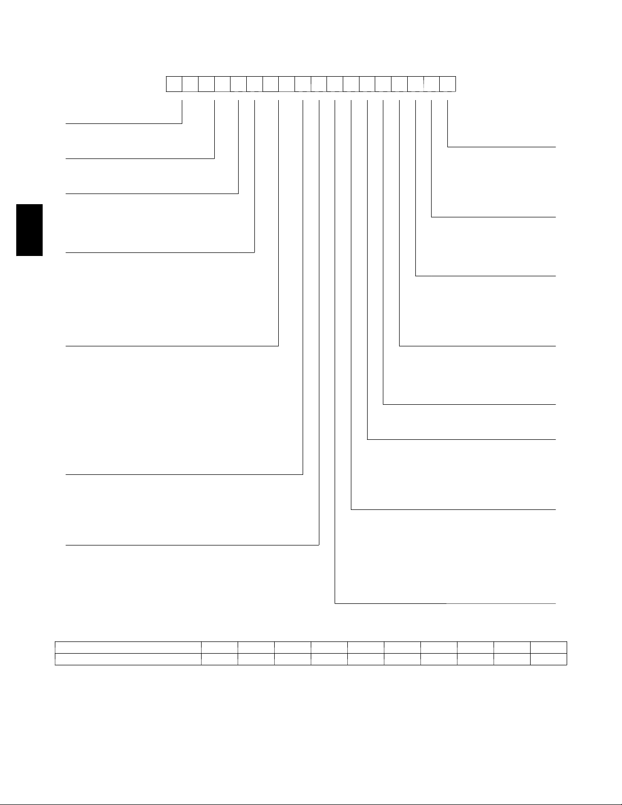
Model Number Nomenclature
Unit Heat Type Brand / Packaging
50 = Elec heat pkg rooftop 0=Standard
Tier / Model
TC = Entry tier (with Puron)
Heat Size A=None
--- = N o h e at C = N on --- f u s e d d isc
Refrig. System Options
50TC
A = Standard refrigeration system Service Options
D=2comp.upgrade 0=None
Cooling Tons Intake / Exhaust Options
04 = 3 Ton A=None
05 = 4 Ton B=Tempeconow/barorelief
06 = 5 Ton F = Enthalpy econo w/ baro relief
07 = 6 Ton K = 2 pos damper w/ baro relief
APPENDIX I. MODEL NUMBER SIGNIFICANCE
123456789101112131415161718
5 0 T C -- A 0 6 A 0 A 5 A 0 A 0 A 0
____ ____ ____
1=LTL
Electrical Options
D=Thruthebase
F = Non---fused & thru the base
1 = Unpowered convenience outlet
2 = Powered convenience outlet
Base Unit Controls
Sensor Options 0 = Electromechanical
A=None 1 = PremierLink DDC controller
B = RA smoke detector 2 = Open protocol DDC controller
C = SA smoke detector
D=RA&SAsmokedetector Design Rev
E=CO2sensor Factory assigned
F = RA smoke detector & CO
G = SA smoke detector & CO
H=RA&SAsmokedetector&CO
Indoor Fan Options 6 = 460/3/60
1 = Standard static option
2 = Medium static option Coil Options (Outdoor Coil --- Indoor Coil)
3 = High static option A = Al/Cu --- Al/Cu
2
2
2
Voltage
1 = 575/3/60
3 = 208 --- 230/1/60
5 = 208 --- 230/3/60
B = P r e coat A l / C u --- A l / C u
C = E coa t A l / C u --- A l / C u
D=EcoatAl/Cu --- EcoatAl/Cu
E = Cu/Cu --- Al/Cu
F = Cu/Cu --- Cu/Cu
Serial Number Format
POSITION NUMBER 1 2 3 4 5 6 7 8 9 10
TYPICAL 1 2 0 8 G 1 2 3 4 6
POSITION DESIGNATES
1---2 Week of manufacture (fiscal calendar
3---4 Year of manufacture (“08” = 2008)
5 Manufacturing location (G = ETP, Texas, USA)
6--- 10 Sequential number
52
Page 53

APPENDIX II. PHYSICAL DATA
Physical Data (Cooling) 3 -- 6 TONS
50TC**04 50TC**05 50TC**06 50TC**07
Refrigeration System
#Circuits/#Comp./Type 1/1/Scroll 1/1/Scroll 1/1/Scroll 1/1/Scroll
Puron (R---410a) charge A/B (lbs) 5.6 8.5 10.7 14.1
Oil A/B (oz) 25 42 42 56
Metering Device Acutrol Acutrol Acutrol Acutrol
High--- press. Trip / Reset (psig) 630 / 505 630 / 505 630 / 505 630 / 505
Low--- press. Trip / Reset (psig) 54 / 117 54 / 117 54 / 117 54 / 117
Evap. Coil
Material Cu / Al Cu / Al Cu / Al Cu / Al
Coil type 3/8” RTPF 3/8” RTPF 3/8” RTPF 3/8” RTPF
Rows / FPI 2 / 15 2/15 4/15 4/15
Tota l Fac e A r ea ( f t2)5.5 5.5 5.5 7.3
Condensate Drain Conn. Size 3/4” 3/4” 3/4” 3/4”
Evap. Fan and Motor
Motor Qty / Drive Type 1/Belt
Max BHP 1.2
RPM Range 560 --- 854 560---854 770--- 1175 ---
1phase
Standard Static
3phase
Standard Static
1phase
Medium Static
3phase
Medium Static
3phase
High Static
Motor Frame Size 48 48 48 ---
Fan Qty / Type 1/Centrifugal 1/Centrifugal 1/Centrifugal ---
Fan Diameter (in) 10 x 10 10 x 10 10 x 10 ---
Motor Qty / Drive Type 1/Belt 1/Belt 1/Belt 1/Belt
Max BHP 1.2 1.2 1.2 2.4
RPM Range 560 --- 854 560---854 770--- 1175 1073 --- 1457
Motor Frame Size 48 48 48 56
Fan Qty / Type 1/Centrifugal 1/Centrifugal 1/Centrifugal 1/Centrifugal
Fan Diameter (in) 10 x 10 10 x 10 10 x 10 10 x 10
Motor Qty / Drive Type 1/Belt 1/Belt 1/Belt ---
Max BHP 1.2 1.2 1.5 ---
RPM Range 770- -- 1175 770---1175 1035--- 1466 ---
Motor Frame Size 48 56 56 ---
Fan Qty / Type 1/Centrifugal 1/Centrifugal 1/Centrifugal ---
Fan Diameter (in) 10 x 10 10 x 10 10 x 10 ---
Motor Qty / Drive Type 1/Belt 1/Belt 1/Belt 1/Belt
Max BHP 1.2 1.2 2.4 2.9
RPM Range 770- -- 1175 770---1175 1035--- 1466 1173--- 1788
Motor Frame Size 48 48 56 56
Fan Qty / Type 1/Centrifugal 1/Centrifugal 1/Centrifugal 1/Centrifugal
Fan Diameter (in) 10 x 10 10 x 10 10 x 10 10 x 10
Motor Qty / Drive Type 1/Belt 1/Belt 1/Belt 1/Belt
Max BHP 2.4 2.4 2.9 3.7
RPM Range 1035--- 1466 1035--- 1466 1303---1687 1474---1788
Motor Frame Size 56 56 56 56
Fan Qty / Type 1/Centrifugal 1/Centrifugal 1/Centrifugal 1/Centrifugal
Fan Diameter (in) 10 x 10 10 x 10 10 x 10 10 x 10
1/Belt 1/Belt ---
1.2 1.2 ---
50TC
Cond. Coil
Cond. fan / motor
Filters
Material Cu / Al Cu / Al Cu / Al Cu / Al
Coil type 3/8” RTPF 3/8” RTPF 3/8” RTPF 3/8” RTPF
Rows / FPI 1 / 17 2/17 2/17 2/17
Tota l Fac e A r ea ( f t2) 14.6 12.6 16.5 21.3
Qty / Motor Drive Type 1/ Direct 1/ Direct 1/ Direct 1/ Direct
Motor HP / RPM 1/4 / 1100 1/4 / 1100 1/4 / 1100 1/4 / 1100
Fan diameter (in) 22 22 22 22
RAFilter#/Size(in) 2/16x25x2 2/16x25x2 2/16x25x2 4/16x16x2
OA inlet sc reen # / Size (in) 1/20x24x1 1/20x24x1 1/20x24x1 1/20x24x1
53
Page 54

APPENDIX III. FAN PERFORMANCE
General Fan Performance Notes:
1. Interpolation is permissible. Do not extra polate.
2. External static pressure is the static pressure difference between the return duct and the supply duct plus the static
pressure caused by any FIOPs or accessories.
3. Tabular data accounts for pressure loss due to clean filters, unit casing, and wet coils. Factory options and accessories
may add static pressure losses. Selection software is available, through your salesperson, to help you select the best
motor/drive combination for your a pplication.
4. The Fan Performance tables offer motor/drive recommendations. In cases when two motor/drive combinations would
work, Carrier recommended the lower horsepower option.
5. For information on the electrical properties of Carrier’s motors, please see the Electrical information section of this
book.
6. For more information on the performance limits of Carrier’s motors, see the application data section of this book.
50TC
54
Page 55

APPENDIX III. FAN PERFORMANCE (cont.)
50TC**04 1 Phase 3 Ton Horizontal Supply
AVAILABLEEXTERNALSTATICPRESSURE(IN.WG)
CFM
FieldSuppliedDrive
900 554 0.14 681 0.22 783 0.32 870 0.42 947 0.53
975 575 0.16 701 0.25 801 0.35 888 0.45 965 0.57
1050 597 0.18 721 0.28 821 0.38 906 0.49 983 0.61
1125 620 0.21 741 0.31 840 0.42 925 0.54 1001 0.66
1200 643 0.23 762 0.35 860 0.46 944 0.58 1020 0.71
1275 666 0.27 784 0.38 880 0.50 964 0.63 1039 0.76
1350 690 0.30 805 0.42 900 0.55 983 0.68 1058 0.82
1425 714 0.34 827 0.47 921 0.60 1003 0.74 1077 0.88
1500 738 0.38 849 0.52 942 0.66 1024 0.80 1097 0.95
CFM
900 1017 0.64 1082 0.76 1143 0.88 1200 1.01 1254 1.14
975 1035 0.68 1100 0.81 1160 0.93 1217 1.07 1271 1.20
1050 1053 0.73 1117 0.86 1177 0.99 1234 1.13 --- ---
1125 1071 0.78 1135 0.92 1195 1.05 1251 1.19 --- ---
1200 1089 0.84 1153 0.98 1212 1.12 --- --- --- ---
1275 1107 0.90 1171 1.04 1230 1.19 --- --- --- ---
1350 1126 0.96 1189 1.11 --- --- --- --- --- ---
1425 1145 1.03 1208 1.18 --- --- --- --- --- ---
1500 1164 1.10 --- --- --- --- --- --- --- ---
NOTE: For more information, see General Fan Performance Notes on page 54.
Boldface indicates field ---supplied drive is required.
1. Recommend using field --- supplied fan pulley (part number KR11AG006) and belt (part number KR30AE039).
2. Recommend using field---supplied motor pulley (part number KR11HY161) and belt (part number KR30AE035).
0.2 0.4 0.6 0.8 1.0
RPM BHP RPM BHP RPM BHP RPM BHP RPM BHP
1.2 1.4 1.6 1.8 2.0
RPM BHP RPM BHP RPM BHP RPM BHP RPM BHP
1
AVAILABLEEXTERNALSTATICPRESSURE(IN.WG)
Medium Static Option
Standard Static Option Medium Static Option
50TC
50TC**04 1 Phase 3 Ton Vertical Supply
AVAILABLEEXTERNALSTATICPRESSURE(IN.WG)
CFM
FieldSuppliedDrive
900 566 0.14 690 0.23 791 0.32 879 0.42 957 0.52
975 590 0.17 711 0.26 811 0.36 897 0.46 975 0.57
1050 615 0.19 733 0.29 831 0.39 916 0.50 993 0.62
1125 640 0.22 755 0.33 851 0.43 936 0.55 1012 0.67
1200 666 0.25 778 0.36 873 0.48 956 0.60 1031 0.72
1275 692 0.29 802 0.41 894 0.53 976 0.65 1051 0.78
1350 719 0.33 825 0.45 916 0.58 997 0.71 1071 0.84
1425 746 0.37 850 0.50 939 0.63 1019 0.77 1091 0.91
1500 774 0.42 875 0.55 962 0.69 1041 0.83 1112 0.98
CFM
900 1029 0.63 1095 0.75 1157 0.86 1216 0.99 1272 1.11
975 1046 0.68 1112 0.80 1174 0.92 1232 1.05 1287 1.18
1050 1064 0.73 1129 0.86 1190 0.98 1248 1.11 --- ---
1125 1082 0.79 1147 0.92 1208 1.05 1265 1.18 --- ---
1200 1100 0.85 1165 0.98 1225 1.12 --- --- --- ---
1275 1119 0.91 1183 1.05 1243 1.19 --- --- --- ---
1350 1139 0.98 1202 1.12 --- --- --- --- --- ---
1425 1159 1.05 1221 1.20 --- --- --- --- --- ---
1500 1179 1.13 --- --- --- --- --- --- --- ---
NOTE: For more information, see General Fan Performance Notes on page 54.
Boldface indicates field ---supplied drive is required.
1. Recommend using field --- supplied fan pulley (part number KR11AG006) and belt (part number KR30AE039).
2. Recommend using field---supplied motor pulley (part number KR11HY161) and belt (part number KR30AE035).
0.2 0.4 0.6 0.8 1.0
RPM BHP RPM BHP RPM BHP RPM BHP RPM BHP
1.2 1.4 1.6 1.8 2.0
RPM BHP RPM BHP RPM BHP RPM BHP RPM BHP
1
AVAILABLEEXTERNALSTATICPRESSURE(IN.WG)
Medium Static Option
Standard Static Option Medium Static Option
55
Page 56

APPENDIX III. FAN PERFORMANCE (cont.)
50TC**04 3 Phase 3 Ton Horizontal Supply
AVAILABLEEXTERNALSTATICPRESSURE(IN.WG)
CFM
FieldSuppliedDrive
900 554 0.14 681 0.22 783 0.32 870 0.42 947 0.53
975 575 0.16 701 0.25 801 0.35 888 0.45 965 0.57
1050 597 0.18 721 0.28 821 0.38 906 0.49 983 0.61
1125 620 0.21 741 0.31 840 0.42 925 0.54 1001 0.66
1200 643 0.23 762 0.35 860 0.46 944 0.58 1020 0.71
1275 666 0.27 784 0.38 880 0.50 964 0.63 1039 0.76
1350 690 0.30 805 0.42 900 0.55 983 0.68 1058 0.82
1425 714 0.34 827 0.47 921 0.60 1003 0.74 1077 0.88
1500 738 0.38 849 0.52 942 0.66 1024 0.80 1097 0.95
50TC
CFM
900 1017 0.64 1082 0.76 1143 0.88 1200 1.01 1254 1.14
975 1035 0.68 1100 0.81 1160 0.93 1217 1.07 1271 1.20
1050 1053 0.73 1117 0.86 1177 0.99 1234 1.13 1288 1.27
1125 1071 0.78 1135 0.92 1195 1.05 1251 1.19 1305 1.34
1200 1089 0.84 1153 0.98 1212 1.12 1269 1.26 1322 1.41
1275 1107 0.90 1171 1.04 1230 1.19 1286 1.33 1340 1.49
1350 1126 0.96 1189 1.11 1249 1.26 1304 1.41 1357 1.57
1425 1145 1.03 1208 1.18 1267 1.33 1323 1.49 1375 1.66
1500 1164 1.10 1227 1.25 1285 1.41 1341 1.58 1394 1.75
NOTE: For more information, see General Fan Performance Notes on page 54.
Boldface indicates field ---supplied drive is required.
1. Recommend using field --- supplied fan pulley (part number KR11AG006) and belt (part number KR30AE039).
0.2 0.4 0.6 0.8 1.0
RPM BHP RPM BHP RPM BHP RPM BHP RPM BHP
1.2 1.4 1.6 1.8 2.0
RPM BHP RPM BHP RPM BHP RPM BHP RPM BHP
1
Medium Static Option High Static Option
Standard Static Option Medium Static Option
AVAILABLEEXTERNALSTATICPRESSURE(IN.WG)
50TC**04 3 Phase 3 Ton Vertical Supply
AVAILABLEEXTERNALSTATICPRESSURE(IN.WG)
CFM
FieldSuppliedDrive
900 566 0.14 690 0.23 791 0.32 879 0.42 957 0.52
975 590 0.17 711 0.26 811 0.36 897 0.46 975 0.57
1050 615 0.19 733 0.29 831 0.39 916 0.50 993 0.62
1125 640 0.22 755 0.33 851 0.43 936 0.55 1012 0.67
1200 666 0.25 778 0.36 873 0.48 956 0.60 1031 0.72
1275 692 0.29 802 0.41 894 0.53 976 0.65 1051 0.78
1350 719 0.33 825 0.45 916 0.58 997 0.71 1071 0.84
1425 746 0.37 850 0.50 939 0.63 1019 0.77 1091 0.91
1500 774 0.42 875 0.55 962 0.69 1041 0.83 1112 0.98
CFM
900 1029 0.63 1095 0.75 1157 0.86 1216 0.99 1272 1.11
975 1046 0.68 1112 0.80 1174 0.92 1232 1.05 1287 1.18
1050 1064 0.73 1129 0.86 1190 0.98 1248 1.11 1304 1.25
1125 1082 0.79 1147 0.92 1208 1.05 1265 1.18 1320 1.32
1200 1100 0.85 1165 0.98 1225 1.12 1282 1.26 1337 1.40
1275 1119 0.91 1183 1.05 1243 1.19 1300 1.34 1354 1.49
1350 1139 0.98 1202 1.12 1262 1.27 1318 1.42 1372 1.57
1425 1159 1.05 1221 1.20 1280 1.35 1336 1.51 1390 1.66
1500 1179 1.13 1241 1.28 1300 1.44 1355 1.60 1408 1.76
NOTE: For more information, see General Fan Performance Notes on page 54.
Boldface indicates field ---supplied drive is required.
1. Recommend using field --- supplied fan pulley (part number KR11AG006) and belt (part number KR30AE039).
0.2 0.4 0.6 0.8 1.0
RPM BHP RPM BHP RPM BHP RPM BHP RPM BHP
1.2 1.4 1.6 1.8 2.0
RPM BHP RPM BHP RPM BHP RPM BHP RPM BHP
1
Medium Static Option High Static Option
Standard Static Option Medium Static Option
AVAILABLEEXTERNALSTATICPRESSURE(IN.WG)
56
Page 57

APPENDIX III. FAN PERFORMANCE (cont.)
50TC**05 1 Phase 4 Ton Horizontal Supply
AVAILABLEEXTERNALSTATICPRESSURE(IN.WG)
CFM
1200 643 0.23 762 0.35 860 0.46 944 0.58 1020 0.71
1300 674 0.28 791 0.40 887 0.52 970 0.65 1045 0.78
1400 706 0.33 820 0.45 914 0.59 997 0.72 1071 0.86
1500 738 0.38 849 0.52 942 0.66 1024 0.80 1097 0.95
1600 771 0.44
1700 804 0.51 910 0.66 1000 0.82 1079 0.98 1151 1.14
1800 837 0.59 941 0.75 1029 0.91 1107 1.08 --- --1900 871 0.67 972 0.84 1059 1.02 1136 1.19 --- --2000 906 0.76 1004 0.94 1089 1.12 --- --- --- ---
CFM
1200 1089 0.84 1153 0.98 1212 1.12 --- --- --- ---
1300 1114 0.92 1177 1.06 --- --- --- --- --- --1400 1139 1.01 1202 1.15 --- --- --- --- --- --1500 1164 1.10 --- --- --- --- --- --- --- --1600 1190 1.20 --- --- --- --- --- --- --- --1700 --- --- --- --- --- --- --- --- --- --1800 --- --- --- --- --- --- --- --- --- --1900 --- --- --- --- --- --- --- --- --- --2000 --- --- --- --- --- --- --- --- --- ---
NOTE: For more information, see General Fan Performance Notes on page 54.
Boldface indicates field ---supplied drive is required.
1. Recommend using field---supplied motor pulley (part number KR11HY161) and belt (part number KR30AE035).
0.2 0.4 0.6 0.8 1.0
RPM BHP RPM BHP RPM BHP RPM BHP RPM BHP
Standard Static Option Medium Static Option
879
1.2 1.4 1.6 1.8 2.0
RPM BHP RPM BHP RPM BHP RPM BHP RPM BHP
Medium Static Option
0.59 971 0.74 1051 0.89 1124 1.04
AVAILABLEEXTERNALSTATICPRESSURE(IN.WG)
50TC
50TC**05 1 Phase 4 Ton Vertical Supply
AVAILABLEEXTERNALSTATICPRESSURE(IN.WG)
CFM
1200 666 0.25 778 0.36 873 0.48 956 0.60 1031 0.72
1300 701 0.30 809 0.42 902 0.54 983 0.67 1057 0.80
1400 737 0.36
1500 774 0.42 875 0.55 962 0.69 1041 0.83 1112 0.98
1600 811 0.49 909 0.63 994 0.78 1071 0.93 1141 1.08
1700 849 0.57 943 0.72 1026 0.87 1101 1.03 1170 1.19
1800 887 0.65 978 0.81 1059 0.98 1133 1.14 --- --1900 926 0.75 1014 0.92 1092 1.09 --- --- --- --2000 965 0.86 1050 1.03 --- --- --- --- --- ---
CFM
Medium Static Option
1200 1100 0.85 1165 0.98 1225 1.12 --- --- --- --1300 1126 0.94 1189 1.07 --- --- --- --- --- --1400 1152 1.03 1215 1.17 --- --- --- --- --- --1500
1600 1206 1.24 --- --- --- --- --- --- --- ---
1700 1235 1.36 --- --- --- --- --- --- --- ---
1800 1264 1.48 --- --- --- --- --- --- --- ---
1900 1293 1.62 --- --- --- --- --- --- --- ---
2000 1324 1.77 --- --- --- ---
NOTE: For more information, see General Fan Performance Notes on page 54.
Boldface indicates field ---supplied drive is required.
1. Recommend using field---supplied motor pulley (part number KR11HY161) and belt (part number KR30AE035).
0.2 0.4 0.6 0.8 1.0
RPM BHP RPM BHP RPM BHP RPM BHP RPM BHP
Standard Static Option Medium Static Option
842
1.2 1.4 1.6 1.8 2.0
RPM BHP RPM BHP RPM BHP RPM BHP RPM BHP
1179 1.13 --- --- --- --- --- --- --- ---
0.48 932 0.61 1012 0.75 1085 0.89
AVAILABLEEXTERNALSTATICPRESSURE(IN.WG)
--- --- --- ---
57
Page 58

APPENDIX III. FAN PERFORMANCE (cont.)
50TC**05 3 Phase 4 Ton Horizontal Supply
AVAILABLEEXTERNALSTATICPRESSURE(IN.WG)
CFM
1200 643 0.23 762 0.35 860 0.46 944 0.58 1020 0.71
1300 674 0.28 791 0.40 887 0.52 970 0.65 1045 0.78
1400 706 0.33 820 0.45 914 0.59 997 0.72 1071 0.86
1500 738 0.38 849 0.52 942 0.66 1024 0.80 1097 0.95
1600 771 0.44
1700 804 0.51 910 0.66 1000 0.82 1079 0.98 1151 1.14
1800 837 0.59 941 0.75 1029 0.91 1107 1.08 1178 1.25
1900 871 0.67 972 0.84 1059 1.02 1136 1.19 1206 1.37
2000 906 0.76 1004 0.94 1089 1.12 1165 1.31 1234 1.49
50TC
CFM
1200 1089 0.84 1153 0.98 1212 1.12 1269 1.26 1322 1.41
1300 1114 0.92 1177 1.06 1236 1.21 1292 1.36 1346 1.52
1400 1139 1.01 1202 1.15 1261 1.31 1316 1.47 1369 1.63
1500 1164 1.10 1227 1.25 1285 1.41 1341 1.58 1394 1.75
1600 1190 1.20 1252 1.36 1311 1.53 1366 1.70 1418 1.87
1700 1217 1.31 1278 1.48 1336 1.65 1391 1.83 1443 2.01
1800 1244 1.42 1305 1.60 1362 1.78 1416 1.97 1468 2.15
1900 1271 1.55 1331 1.73 1388 1.92 1442 2.11 1494 2.31
2000 1298 1.68 1358 1.87 1415 2.07 1468 2.27 --- ---
NOTE: For more information, see General Fan Performance Notes on page 54.
Boldface indicates field ---supplied drive is required.
1. Recommend using field--- supplied fan pulley (part number KR11AZ506), motor pulley (part number KR11HY181) and belt (part number
KR30AE041).
0.2 0.4 0.6 0.8 1.0
RPM BHP RPM BHP RPM BHP RPM BHP RPM BHP
Standard Static Option Medium Static Option
879
1.2 1.4 1.6 1.8 2.0
RPM BHP RPM BHP RPM BHP RPM BHP RPM BHP
Medium Static Option High Static Option
0.59 971 0.74 1051 0.89 1124 1.04
AVAILABLEEXTERNALSTATICPRESSURE(IN.WG)
50TC**05 3 Phase 4 Ton Vertical Supply
AVAILABLEEXTERNALSTATICPRESSURE(IN.WG)
CFM
1200 666 0.25 778 0.36 873 0.48 956 0.60 1031 0.72
1300 701 0.30 809 0.42 902 0.54 983 0.67 1057 0.80
1400 737 0.36
1500 774 0.42 875 0.55 962 0.69 1041 0.83 1112 0.98
1600 811 0.49 909 0.63 994 0.78 1071 0.93 1141 1.08
1700 849 0.57 943 0.72 1026 0.87 1101 1.03 1170 1.19
1800 887 0.65 978 0.81 1059 0.98 1133 1.14 1200 1.31
1900 926 0.75 1014 0.92 1092 1.09 1164 1.26 1231 1.44
2000 965 0.86 1050 1.03 1127 1.21 1197 1.39 1262 1.58
CFM
Medium Static Option High Static Option
1200 1100 0.85 1165 0.98 1225 1.12 1282 1.26 1337 1.40
1300 1126 0.94 1189 1.07 1249 1.22 1306 1.36 1360 1.51
1400 1152 1.03 1215 1.17 1274 1.32 1330 1.48 1384 1.63
1500
1600 1206 1.24 1268 1.40 1326 1.56 1381 1.73 1433 1.90
1700 1235 1.36 1295 1.52 1352 1.69 1407 1.87 1459 2.04
1800 1264 1.48 1323 1.66 1380 1.84 1434 2.02 1485 2.20
1900 1293 1.62 1352 1.80 1408 1.99 1461 2.17 1512 2.37
2000 1324 1.77 1381 1.96 1436 2.15
NOTE: For more information, see General Fan Performance Notes on page 54.
Boldface indicates field ---supplied drive is required.
1. Recommend using field--- supplied fan pulley (part number KR11AZ506), motor pulley (part number KR11HY181) and belt (part number
KR30AE041).
0.2 0.4 0.6 0.8 1.0
RPM BHP RPM BHP RPM BHP RPM BHP RPM BHP
Standard Static Option Medium Static Option
842
1.2 1.4 1.6 1.8 2.0
RPM BHP RPM BHP RPM BHP RPM BHP RPM BHP
1179 1.13 1241 1.28 1300 1.44 1355 1.60 1408 1.76
0.48 932 0.61 1012 0.75 1085 0.89
AVAILABLEEXTERNALSTATICPRESSURE(IN.WG)
1489 2.34 --- ---
58
Page 59

APPENDIX III. FAN PERFORMANCE (cont.)
50TC**06 1 Phase 5 Ton Horizontal Supply
AVAILABLEEXTERNALSTATICPRESSURE(IN.WG)
CFM
FieldSuppliedDrive
1500 724 0.33 837 0.45 937 0.59 1028 0.74 1111 0.91
1625 765 0.40 873 0.53 969 0.67 1056 0.83 1137 1.00
1750
1875 849 0.57 947 0.71 1036 0.86 1118 1.03 1195 1.21
2000 892 0.67 986 0.82 1072 0.98 1151 1.15 1226 1.33
2125 935 0.79 1025 0.94 1108 1.11
2250 980 0.92 1066 1.08 1146 1.25 1220 1.43 --- --2375 1024 1.06 1107 1.23 1184 1.41 --- --- --- --2500 1069 1.22 1149 1.39 --- --- --- --- --- ---
CFM
1500 1188 1.09 1261 1.29 1330 1.49 --- --- --- --1625 1213 1.18 1284 1.38 -- - --- --- --- --- --1750 1239 1.28 1309 1.49 -- - --- --- --- --- --1875 1267 1.40 --- --- --- --- --- --- --- --2000
2125 --- --- --- --- --- --- --- --- --- --2250 --- --- --- --- --- --- --- --- --- --2375 --- --- --- --- --- --- --- --- --- --2500 --- --- --- --- --- --- --- --- --- ---
NOTE: For more information, see General Fan Performance Notes on page 54.
Boldface indicates field ---supplied drive is required.
1. Recommend using field --- supplied fan pull ey (part number KR11AZ606) and belt (part number KR30AE037).
0.2 0.4 0.6 0.8 1.0
RPM BHP RPM BHP RPM BHP RPM BHP RPM BHP
806 0.48 909 0.61 1002 0.76 1087 0.92 1165 1.10
1.2 1.4 1.6 1.8 2.0
RPM BHP RPM BHP RPM BHP RPM BHP RPM BHP
--- --- --- --- --- ---
1
AVAILABLEEXTERNALSTATICPRESSURE(IN.WG)
Medium Static Option
Standard Static Option
1185
---
1.29 1258 1.47
--- --- ---
50TC
50TC**06 1 Phase 5 Ton Vertical Supply
AVAILABLEEXTERNALSTATICPRESSURE(IN.WG)
CFM
1500 790 0.40 897 0.53 991 0.68 1075 0.83 1152 1.00
1625 837 0.48 940 0.62 1030 0.77 1112 0.94 1187 1.11
1750 885 0.58 983 0.73 1070 0.89 1150 1.06 1223 1.24
1875 934 0.69 1027 0.85 1112 1.01
2000 983 0.81 1073 0.98 1154 1.16 1229 1.34 --- --2125 1033 0.95 1119 1.13 1198 1.31 1270 1.50 --- --2250 1084 1.11 1166 1.29 1242 1.49 --- --- --- --2375 1134 1.28 1214 1.48 --- --- --- --- --- --2500 1185 1.48 --- --- --- --- --- --- --- ---
CFM
1500 1224 1.18 1291 1.36 --- --- --- --- --- --1625 1257 1.30 1323 1.49 -- - --- --- --- --- --1750 1292 1.43 --- --- --- --- --- --- --- --1875
2000 --- --- --- --- --- --- --- --- --- --2125 --- --- --- --- --- --- --- --- --- --2250 --- --- --- --- --- --- --- --- --- --2375 --- --- --- --- --- --- --- --- --- --2500 --- --- --- --- --- --- --- --- --- ---
NOTE: For more information, see General Fan Performance Notes on page 54.
Boldface indicates field ---supplied drive is required.
0.2 0.4 0.6 0.8 1.0
RPM BHP RPM BHP RPM BHP RPM BHP RPM BHP
Standard Static Option
1189
AVAILABLEEXTERNALSTATICPRESSURE(IN.WG)
1.2 1.4 1.6 1.8 2.0
RPM BHP RPM BHP RPM BHP RPM BHP RPM BHP
Medium Static Option
--- --- --- --- --- ---
---
1.19 1260 1.38
--- --- ---
59
Page 60

APPENDIX III. FAN PERFORMANCE (cont.)
50TC**06 3 Phase 5 Ton Horizontal Supply
AVAILABLEEXTERNALSTATICPRESSURE(IN.WG)
CFM
FieldSuppliedDrive
1500 724 0.33 837 0.45 937 0.59 1028 0.74 1111 0.91
1625 765 0.40 873 0.53 969 0.67 1056 0.83 1137 1.00
1750
1875 849 0.57 947 0.71 1036 0.86 1118 1.03 1195 1.21
2000 892 0.67 986 0.82 1072 0.98 1151 1.15 1226 1.33
2125 935 0.79 1025 0.94 1108 1.11
2250 980 0.92 1066 1.08 1146 1.25 1220 1.43 1291 1.63
2375 1024 1.06 1107 1.23 1184 1.41 1256 1.60 1325 1.79
2500 1069 1.22 1149 1.39 1223 1.58 1293 1.77 1360 1.98
50TC
CFM
1500 1188 1.09 1261 1.29 1330 1.49 1395 1.71 1457 1.95
1625 1213 1.18 1284 1.38 1352 1.59 1416 1.81 1478 2.04
1750 1239 1.28 1309 1.49 1375 1.70 1439 1.92
1875 1267 1.40 1335 1.60 1400 1.82 1462 2.04 1522 2.28
2000 1296 1.53 1363 1.74 1427 1.95
2125 1326 1.67 1392 1.88 1454 2.11 1514 2.34 1571 2.58
2250 1358 1.83 1421 2.05 1483 2.27 1541 2.51 1598 2.75
2375 1390 2.00 1452 2.22 1512 2.45 1570 2.69 1625 2.94
2500 1424 2.19 1484 2.42 1543 2.65 1599 2.89 1654 3.15
NOTE: For more information, see General Fan Performance Notes on page 54.
Boldface indicates field ---supplied drive is required.
1. Recommend using field --- supplied fan pull ey (part number KR11AZ606) and belt (part number KR30AE037).
0.2 0.4 0.6 0.8 1.0
RPM BHP RPM BHP RPM BHP RPM BHP RPM BHP
806 0.48 909 0.61 1002 0.76 1087 0.92 1165 1.10
1.2 1.4 1.6 1.8 2.0
RPM BHP RPM BHP RPM BHP RPM BHP RPM BHP
1
AVAILABLEEXTERNALSTATICPRESSURE(IN.WG)
Medium Static Option
Standard Static Option
1185
1488
1.29 1258 1.47
1499
2.18 1546 2.42
2.16
50TC**06 3 Phase 5 Ton Vertical Supply
AVAILABLEEXTERNALSTATICPRESSURE(IN.WG)
CFM
1500 790 0.40 897 0.53 991 0.68 1075 0.83 1152 1.00
1625 837 0.48 940 0.62 1030 0.77 1112 0.94 1187 1.11
1750 885 0.58 983 0.73 1070 0.89 1150 1.06 1223 1.24
1875 934 0.69 1027 0.85 1112 1.01
2000 983 0.81 1073 0.98 1154 1.16 1229 1.34 1299 1.53
2125 1033 0.95 1119 1.13 1198 1.31 1270 1.50 1338 1.71
2250 1084 1.11 1166 1.29 1242 1.49 1312 1.69 1379 1.89
2375 1134 1.28 1214 1.48 1287 1.68 1355 1.89 1420 2.10
2500 1185 1.48 1262 1.68 1333 1.89 1399 2.10 1462 2.33
CFM
1500 1224 1.18 1291 1.36 1354 1.56 1414 1.77 1472 1.98
1625 1257 1.30 1323 1.49 1385 1.69 1445 1.90 1501 2.12
1750 1292 1.43 1356 1.63 1418 1.83 1476 2.05 1532 2.27
1875 1327 1.57 1391 1.78 1451 1.99
2000 1364 1.74 1427 1.95 1486 2.17 1542 2.39 1596 2.63
2125 1402 1.92 1463 2.13 1521 2.36 1577 2.59 1630 2.83
2250 1441 2.11 1501 2.34 1558 2.57 1612 2.81 --- --2375 1481 2.33 1539 2.56 1595 2.80 --- --- --- --2500 1522 2.56 1579 2.80 --- --- --- --- --- ---
NOTE: For more information, see General Fan Performance Notes on page 54.
Boldface indicates field ---supplied drive is required.
0.2 0.4 0.6 0.8 1.0
RPM BHP RPM BHP RPM BHP RPM BHP RPM BHP
Standard Static Option
1189
AVAILABLEEXTERNALSTATICPRESSURE(IN.WG)
1.2 1.4 1.6 1.8 2.0
RPM BHP RPM BHP RPM BHP RPM BHP RPM BHP
Medium Static Option
1509
1.19 1260 1.38
2.21 1564 2.44
60
Page 61

APPENDIX III. FAN PERFORMANCE (cont.)
50TC**07 3 Phase 6 Ton Horizontal Supply
AVAILABLEEXTERNALSTATICPRESSURE(IN.WG)
CFM
FieldSuppliedDrive
1800 822 0.51 927 0.66 1018 0.82 1100 0.98 1174 1.15
1950 872 0.62 973 0.79 1061 0.95 1140 1.13 1213 1.31
2100 923 0.75 1019 0.92
2250 974 0.90 1067 1.08 1149 1.27 1224 1.46 1294 1.66
2400 1026 1.06 1115 1.26 1195 1.46 1268 1.66 1336 1.87
2550 1079 1.25 1164 1.46 1241 1.67 1312 1.88 1379 2.10
2700 1132 1.46 1214 1.67 1289 1.90 1358 2.12 1422 2.35
2850 1186 1.69 1264 1.92 1336 2.15 1404 2.39 1467 2.63
3000 1240 1.94 1315 2.18 1385 2.43 1451 2.68 1512 2.93
CFM
1800 1244 1.33 1308 1.51 1369 1.70 1427 1.90 1483 2.10
1950 1281 1.49 1345 1.68 1405 1.88 1462 2.09 1517 2.30
2100 1320 1.67 1382 1.87 1441 2.08 1498 2.29 1552 2.51
2250 1359 1.87 1420 2.08 1479 2.29 1534 2.51 1587 2.74
2400 1400 2.09 1460 2.31 1517 2.53 1572 2.76 1624 2.99
2550 1441 2.33 1500 2.55 1557 2.79 1610 3.03 1662 3.27
2700 1483 2.59 1541 2.83 1597 3.07 1650 3.32 1701 3.57
2850 1527 2.87 1583 3.12 1638 3.37 1690 3.63 --- --3000 1571 3.18 1626 3.44 1680 3.70 --- --- --- ---
NOTE: For more information, see General Fan Performance Notes on page 543.
Boldface indicates field ---supplied drive is required.
1. Recommend using field--- supplied fan pulley (part number KR11AZ406), motor pulley (part number KR11HY151) and belt (part number
KR30AE035).
50TC**07 3 Phase 6 Ton Vertical Supply
0.2 0.4 0.6 0.8 1.0
RPM BHP RPM BHP RPM BHP RPM BHP RPM BHP
1.2 1.4 1.6 1.8 2.0
RPM BHP RPM BHP RPM BHP RPM BHP RPM BHP
1
1104
AVAILABLEEXTERNALSTATICPRESSURE(IN.WG)
Standard Static Option Medium Static Option
Standard Static Option
1.10 1182 1.29 1253 1.48
50TC
AVAILABLEEXTERNALSTATICPRESSURE(IN.WG)
CFM
FieldSuppliedDrive
1800 907 0.63 1006 0.80 1092 0.97 1169 1.14 1239 1.32
1950 965 0.77 1060 0.95 1143 1.13 1218 1.32 1287 1.51
2100 1024 0.93 1115 1.12 1195 1.32 1268 1.52 1335 1.72
2250 1083 1.11 1170 1.32 1248 1.53 1319 1.74 1385 1.96
2400 1143 1.32 1227 1.54 1302 1.76 1371 1.99 1435 2.22
2550 1203 1.55 1284 1.78 1357 2.02 1424 2.26 1487 2.50
2700 1264 1.81 1342 2.06 1412 2.31 1478 2.56 1539 2.82
2850 1326 2.09 1400 2.36 1469 2.62 1532 2.89 1592 3.16
3000 1387 2.41 1459 2.69 1525 2.97 1587 3.25 1646 3.53
CFM
1800 1304 1.51 1365 1.69 1422 1.88 1477 2.08 1528 2.28
1950 1350 1.71 1410 1.91 1467 2.11 1520 2.31 1572 2.52
2100 1398 1.93 1457 2.14 1512 2.35 1565 2.57 1616 2.79
2250 1446 2.18 1504 2.40 1559 2.62 1611 2.85 1661 3.09
2400 1496 2.45 1552 2.68 1606 2.92 1658 3.16 1707 3.40
2550 1546 2.75 1601 2.99 1654 3.24 1705 3.50 --- --2700 1597 3.07 1651 3.33 1703 3.59 --- --- --- --2850 1648 3.43 1702 3.70 -- - --- --- --- --- --3000 --- --- --- --- --- --- --- --- --- ---
NOTE: For more information, see General Fan Performance Notes on page 54.
Boldface indicates field ---supplied drive is required.
1. Recommend using field--- supplied fan pulley (part number KR11AZ406), motor pulley (part number KR11HY151) and belt (part number
KR30AE035).
0.2 0.4 0.6 0.8 1.0
RPM BHP RPM BHP RPM BHP RPM BHP RPM BHP
1.2 1.4 1.6 1.8 2.0
RPM BHP RPM BHP RPM BHP RPM BHP RPM BHP
1
AVAILABLEEXTERNALSTATICPRESSURE(IN.WG)
Standard Static Option Medium Static Option
Standard Static Option
61
Page 62

Pulley Adjustment
UNIT
1phase
04
3phase
1phase
05
50TC
3phase
1phase
06
3phase
07
3phase
APPENDIX III. FAN PERFORMANCE (cont.)
MOTOR/DRIVE
COMBO
Standard Static 854 825 795 766 736 707 678 648 619 589 560
Medium Static 1175 1135 1094 1054 1013 973 932 892 851 811 770
High Static --- --- --- --- --- --- --- --- --- --- ---
Standard Static 854 825 795 766 736 707 678 648 619 589 560
Medium Static 1175 1135 1094 1054 1013 973 932 892 851 811 770
High Static 1466 1423 1380 1337 1294 1251 1207 1164 1121 1078 1035
Standard Static 854 825 795 766 736 707 678 648 619 589 560
Medium Static 1175 1135 1094 1054 1013 973 932 892 851 811 770
High Static --- --- --- --- --- --- --- --- --- --- ---
Standard Static 854 825 795 766 736 707 678 648 619 589 560
Medium Static 1175 1135 1094 1054 1013 973 932 892 851 811 770
High Static 1466 1423 1380 1337 1294 1251 1207 1164 1121 1078 1035
Standard Static 1175 1135 1094 1054 1013 973 932 892 851 811 770
Medium Static 1466 1423 1380 1337 1294 1251 1207 1164 1121 1078 1035
High Static --- --- --- --- --- --- --- --- --- --- ---
Standard Static 1175 1135 1094 1054 1013 973 932 892 851 811 770
Medium Static 1466 1423 1380 1337 1294 1251 1207 1164 1121 1078 1035
High Static 1687 1649 1610 1572 1533 1495 1457 1418 1380 1341 1303
Standard Static 1457 1419 1380 1342 1303 1265 1227 1188 1150 1111 1073
Medium Static 1518 1484 1449 1415 1380 1346 1311 1277 1242 1208 1173
High Static 1788 1757 1725 1694 1662 1631 1600 1568 1537 1505 1474
0.0 0.5 1.0 1.5 2.0 2.5 3.0 3.5 4.0 4.5 5.0
MOTOR PULLEY TURNS OPEN
NOTE: Do not adjust pulley further than 5 turns open.
--- F a cto r y s ett i n gs
62
Page 63

50TC**04 3 TONS
APPENDIX IV. ELECTRICAL DATA
VOLTAGE
V --- P h --- H z
2 0 8 --- 1 --- 6 0 187 253 16.6 79 325 1.5
2 3 0 --- 1 --- 6 0 187 253 16.6 79 325 1.5
2 0 8 --- 3 --- 6 0 187 253 10.4 73 325 1.5
2 3 0 --- 3 --- 6 0 187 253 10.4 73 325 1.5
4 6 0 --- 3 --- 6 0 414 506 5.8 38 325 0.8
5 7 5 --- 3 --- 6 0 518 633 3.8 37 325 0.6
RANGE
MIN MAX
COMP (ea) OFM (ea) IFM
RLA LRA WAT TS FLA TYPE
50TC**05 4 TONS
VOLTAGE
V --- P h --- H z
2 0 8 --- 1 --- 6 0 187 253 21.8 117 325 1.5
2 3 0 --- 1 --- 6 0 187 253 21.8 117 325 1.5
2 0 8 --- 3 --- 6 0 187 253 13.7 83 325 1.5
2 3 0 --- 3 --- 6 0 187 253 13.7 83 325 1.5
4 6 0 --- 3 --- 6 0 414 506 6.2 41 325 0.8
5 7 5 --- 3 --- 6 0 518 633 4.8 37 325 0.6
RANGE
MIN MAX
COMP (ea) OFM (ea) IFM
RLA LRA WAT TS FLA TYPE
Max
WATTS
Std Static 1000 5.1 70% 4.9
Med Static 1000 5.1 70% 4.9
Std Static 1000 5.1 70% 4.9
Med Static 1000 5.1 70% 4.9
Std Static 1000 5.1 70% 4.9
Med Static 1000 5.1 70% 4.9
High Static 2120 5.5 80% 5.2
Std Static 1000 5.1 70% 4.9
Med Static 1000 5.1 70% 4.9
High Static 2120 5.5 80% 5.2
Std Static 1000 2.2 70% 2.1
Med Static 2120 2.7 80% 2.6
High Static 2120 2.7 80% 2.6
Std Static 1000 2.0 71% 1.9
Med Static 2120 2.1 80% 2.0
High Static 2120 2.1 80% 2.0
Max
WATTS
Std Static 1000 5.1 70% 4.9
Med Static 1850 7.4 78% 7.0
Std Static 1000 5.1 70% 4.9
Med Static 1850 7.4 78% 7.0
Std Static 1000 5.1 70% 4.9
Med Static 1000 5.1 70% 4.9
High Static 2120 5.5 80% 5.2
Std Static 1000 5.1 70% 4.9
Med Static 1000 5.1 70% 4.9
High Static 2120 5.5 80% 5.2
Std Static 1000 2.2 70% 2.1
Med Static 2120 2.7 80% 2.6
High Static 2120 2.7 80% 2.6
Std Static 1000 2.0 71% 1.9
Med Static 2120 2.1 80% 2.0
High Static 2120 2.1 80% 2.0
Max
AMP Draw
Max
AMP Draw
EFF at Full Load FLA
EFF at Full Load FLA
50TC
63
Page 64

50TC**06 5 TONS
APPENDIX IV. ELECTRICAL DATA (cont.)
VOLTAGE
V --- P h --- H z
2 0 8 --- 1 --- 6 0 187 253 26.2 134 325 1.5
2 3 0 --- 1 --- 6 0 187 253 26.2 134 325 1.5
2 0 8 --- 3 --- 6 0 187 253 15.6 110 325 1.5
2 3 0 --- 3 --- 6 0 187 253 15.6 110 325 1.5
4 6 0 --- 3 --- 6 0 414 506 7.7 52 325 0.8
RANGE
MIN MAX
COMP (ea) OFM (ea) IFM
RLA LRA WAT TS FLA TYPE
50TC
5 7 5 --- 3 --- 6 0 518 633 5.8 39 325 0.6
50TC**07 6 TONS
VOLTAGE
V --- P h --- H z
2 0 8 --- 3 --- 6 0 187 253 19.0 12 325 1.5
2 3 0 --- 3 --- 6 0 187 253 19.0 12 325 1.5
4 6 0 --- 3 --- 6 0 414 506 9.7 62 325 0.8
5 7 5 --- 3 --- 6 0 518 633 7.4 50 325 0.6
RANGE
MIN MAX
COMP (ea) OFM (ea) IFM
RLA LRA WAT TS FLA TYPE
Max
WATTS
Std Static 1000 5.1 70% 4.9
Med Static 1850 7.4 78% 7.0
Std Static 1000 5.1 70% 4.9
Med Static 1850 7.4 78% 7.0
Std Static 1000 5.1 70% 4.9
Med Static 2120 5.5 80% 5.2
High Static 2615 7.9 81% 7.5
Std Static 1000 5.1 70% 4.9
Med Static 2120 5.5 80% 5.2
High Static 2615 7.9 81% 7.5
Std Static 2120 2.7 80% 2.6
Med Static 2615 3.6 81% 3.4
High Static 2615 3.6 81% 3.4
Std Static 2120 2.1 80% 2.0
Med Static 3775 2.9 81% 2.8
High Static 3775 2.9 81% 2.8
Max
WATTS
Std Static 2120 5.5 80% 5.2
Med Static 2615 7.9 81% 7.5
High Static 3775 10.7 81% 10.2
Std Static 2120 5.5 80% 5.2
Med Static 2615 7.9 81% 7.5
High Static 3775 10.7 81% 10.2
Std Static 2120 2.7 80% 2.6
Med Static 2615 3.6 81% 3.4
High Static 3775 5.0 81% 4.8
Std Static 2120 2.1 80% 2.0
Med Static 3775 2.9 81% 2.8
High Static 3775 2.9 81% 2.8
Max
AMP Draw
Max
AMP Draw
EFF at Full Load FLA
EFF at Full Load FLA
64
Page 65

APPENDIX IV. ELECTRICAL DATA (cont.)
MCA/MOCP DETERMINATION NO C.O. OR UNPWRD C.O.
ELECTRIC HEATER NO C.O. or UNPWR C.O.
IFM
UNIT
50TC**04
TYPE
N O M . V --- P H --- H Z
STD
208/230---1---60
MED
STD
MED
208/230---3---60
HIGH
STD
MED
4 6 0 --- 3 --- 6 0
HIGH
STD None None 7.3 15 7 44 9.2 15 9 46
MED None None 7.3 15 7 44 9.2 15 9 46
HIGH None None 7.4 15 7 50 9.3 15 10 52
5 7 5 --- 3 --- 6 0
Nom (kW) FLA
MCA MOCP
None None 27.2 40 26 95 29.1 45 29 97
3.3/4.4 15.9/18.3 27.2/29.0 40/40 26/27 95/95 29.1/31.4 45/45 29/29 97/97
4.9/6.5 23.5/27.1 35.5/40.0 40/45 33/37 95/95 37.9/42.4 45/45 35/39 97/97
6.5/8.7 31.4/36.3 45.4/51.5 50/60 42/47 95/95 47.8/53.9 50/60 44/50 97/97
7.9/10.5 37.9/43.8 53.5/60.9 60/70 49/56 95/95 55.9/63.3 60/70 51/58 97/97
9.8/13.0 46.9/54.2 64.8/73.9 70/80 60/68 95/95 67.1/76.3 70/80 62/70 97/97
None None 19.4 25 19 89 21.3 30 22 91
3.3/4.4 9.2/10.6 19.4/19.4 25/25 19/19 89/89 21.3/21.8 30/30 22/22 91/91
4.9/6.5 13.6/15.6 23.1/25.6 25/30 21/24 89/89 25.5/28.0 30/30 23/26 91/91
6.5/8.7 18.1/20.9 28.8/32.3 30/35 26/30 89/89 31.1/34.6 35/35 29/32 91/91
7.9/10.5 21.9/25.3 33.5/37.8 35/40 31/35 89/89 35.9/40.1 40/45 33/37 91/91
12.0/16.0 33.4/38.5 47.9/54.3 50/60 44/50 89/89 50.3/56.6 60/60 46/52 91/91
None None 19.7 30 20 107 21.6 30 22 109
3.3/4.4 9.2/10.6 19.7/19.8 30/30 20/20 107/107 21.6/22.1 30/30 22/22 109/109
4.9/6.5 13.6/15.6 23.5/26.0 30/30 22/24 107/107 25.9/28.4 30/30 24/26 109/109
6.5/8.7 18.1/20.9 29.1/32.6 30/35 27/30 107/107 31.5/35.0 35/40 29/32 109/109
7.9/10.5 21.9/25.3 33.9/38.1 35/40 31/35 107/107 36.3/40.5 40/45 33/37 109/109
12.0/16.0 33.4/38.5 48.3/54.6 50/60 44/50 107/107 50.6/57.0 60/60 47/52 109/109
None None 10.2 15 10 46 11.2 15 11 47
6.0 7.2 11.6 15 11 46 12.9 15 12 47
8.8 10.6 15.9 20 15 46 17.1 20 16 47
11.5 13.8 19.9 20 18 46 21.1 25 19 47
14.0 16.8 23.6 25 22 46 24.9 25 23 47
None None 10.2 15 10 46 11.2 15 11 47
6.0 7.2 11.6 15 11 46 12.9 15 12 47
8.8 10.6 15.9 20 15 46 17.1 20 16 47
11.5 13.8 19.9 20 18 46 21.1 25 19 47
14.0 16.8 23.6 25 22 46 24.9 25 23 47
None None 10.7 15 11 55 11.7 15 12 56
6.0 7.2 12.3 15 11 55 13.5 15 12 56
8.8 10.6 16.5 20 15 55 17.8 20 16 56
11.5 13.8 20.5 25 19 55 21.8 25 20 56
14.0 16.8 24.3 25 22 55 25.5 30 23 56
NO P.E. w/ P.E. (pwrd fr/unit)
DISC. SIZE
MCA MOCP
FLA LRA FLA LRA
DISC. SIZE
50TC
65
Page 66

APPENDIX IV. ELECTRICAL DATA (cont)
MCA/MOCP DETERMINATION NO C.O. OR UNPWRD C.O. (cont)
ELECTRIC HEATER NO C.O. or UNPWR C.O.
50TC
IFM
UNIT
50TC**05
TYPE
N O M . V --- P H --- H Z
STD
208/230---1---60
MED
STD
MED
208/230---3---60
HIGH
STD
MED
4 6 0 --- 3 --- 6 0
HIGH
STD None None 8.5 15 8 44 10.4 15 11 46
MED None None 8.5 15 8 44 10.4 15 11 46
HIGH None None 8.6 15 9 50 10.5 15 11 52
5 7 5 --- 3 --- 6 0
Nom (kW) FLA
MCA MOCP
None None 33.7 50 32 133 35.6 50 35 135
3.3/4.4 15.9/18.3 33.7/33.7 50/50 32/32 133/133 35.6/35.6 50/50 35/35 135/135
6.5/8.7 31.4/36.3 45.4/51.5 50/60 42/47 133/133 47.8/53.9 50/60 44/50 135/135
9.8/13.0 46.9/54.2 64.8/73.9 70/80 60/68 133/133 67.1/76.3 70/80 62/70 135/135
13.1/17.4 62.8/72.5 84.6/96.8 90/100 78/89 133/133 87.0/99.1 90/100 80/91 135/135
15.8/21.0 75.8/87.5 100.9/115.5 110/125 93/106 133/133 103.3/117.9 110/125 95/108 135/135
None None 23.5 30 23 99 25.4 30 25 101
4.9/6.5 13.6/15.6 23.5/25.6 30/30 23/24 99/99 25.5/28.0 30/30 25/26 101/101
6.5/8.7 18.1/20.9 28.8/32.3 30/35 26/30 99/99 31.1/34.6 35/35 29/32 101/101
12.0/16.0 33.4/38.5 47.9/54.3 50/60 44/50 99/99 50.3/56.6 60/60 46/52 101/101
15.8/21.0 43.8/50.5 60.9/69.3 70/70 56/64 99/99 63.3/71.6 70/80 58/66 101/101
None None 23.8 30 23 117 25.7 30 26 119
4.9/6.5 13.6/15.6 23.8/26.0 30/30 23/24 117/117 25.9/28.4 30/30 26/26 119/119
6.5/8.7 18.1/20.9 29.1/32.6 30/35 27/30 117/117 31.5/35.0 35/40 29/32 119/119
12.0/16.0 33.4/38.5 48.3/54.6 50/60 44/50 117/117 50.6/57.0 60/60 47/52 119/119
15.8/21.0 43.8/50.5 61.3/69.6 70/70 56/64 117/117 63.6/72.0 70/80 59/66 119/119
None None 10.7 15 10 49 11.7 15 12 50
6.0 7.2 11.6 15 11 49 12.9 15 12 50
11.5 13.8 19.9 20 18 49 21.1 25 19 50
14.0 16.8 23.6 25 22 49 24.9 25 23 50
23.0 27.7 37.3 40 34 49 38.5 40 35 50
None None 10.7 15 10 49 11.7 15 12 50
6.0 7.2 11.6 15 11 49 12.9 15 12 50
11.5 13.8 19.9 20 18 49 21.1 25 19 50
14.0 16.8 23.6 25 22 49 24.9 25 23 50
23.0 27.7 37.3 40 34 49 38.5 40 35 50
None None 11.2 15 11 58 12.2 15 12 59
6.0 7.2 12.3 15 11 58 13.5 15 12 59
11.5 13.8 20.5 25 19 58 21.8 25 20 59
14.0 16.8 24.3 25 22 58 25.5 30 23 59
23.0 27.7 37.9 40 35 58 39.1 40 36 59
NO P.E. w/ P.E. (pwrd fr/unit)
DISC. SIZE
MCA MOCP
FLA LRA FLA LRA
DISC. SIZE
66
Page 67

APPENDIX IV. ELECTRICAL DATA (cont)
MCA/MOCP DETERMINATION NO C.O. OR UNPWRD C.O. (cont)
ELECTRIC HEATER NO C.O. or UNPWR C.O.
IFM
UNIT
50TC**06
TYPE
N O M . V --- P H --- H Z
STD
208/230---1---60
MED
STD
MED
208/230---3---60
HIGH
STD
MED
4 6 0 --- 3 --- 6 0
HIGH
STD None None 9.8 15 10 46 11.7 15 12 48
MED None None 9.9 15 10 52 11.8 15 12 54
HIGH None None 10.7 15 11 63 12.6 15 13 65
5 7 5 --- 3 --- 6 0
Nom (kW) FLA
MCA MOCP
None None 39.2 60 37 150 41.1 60 40 152
4.9/6.5 23.5/27.1 39.2/40.0 60/60 37/37 150/150 41.1/42.4 60/60 40/40 152/152
6.5/8.7 31.4/36.3 45.4/51.5 60/60 42/47 150/150 47.8/53.9 60/60 44/50 152/152
9.8/13.0 46.9/54.2 64.8/73.9 70/80 60/68 150/150 67.1/76.3 70/80 62/70 152/152
13.1/17.4 62.8/72.5 84.6/96.8 90/100 78/89 150/150 87.0/99.1 90/100 80/91 152/152
15.8/21.0 75.8/87.5 100.9/115.5 110/125 93/106 150/150 103.3/117.9 110/125 95/108 152/152
None None 41.3 60 40 175 43.2 60 42 177
4.9/6.5 23.5/27.1 41.3/42.6 60/60 40/40 175/175 43.2/45.0 60/60 42/42 177/177
6.5/8.7 31.4/36.3 48.0/54.1 60/60 44/50 175/175 50.4/56.5 60/60 46/52 177/177
9.8/13.0 46.9/54.2 67.4/76.5 70/80 62/70 175/175 69.8/78.9 70/80 64/73 177/177
13.1/17.4 62.8/72.5 87.3/99.4 90/100 80/91 175/175 89.6/101.8 90/110 82/94 177/177
15.8/21.0 75.8/87.5 103.5/118.1 110/125 95/109 175/175 105.9/120.5 110/125 97/111 177/177
None None 25.9 30 25 126 27.8 40 27 128
4.9/6.5 13.6/15.6 25.9/25.9 30/30 25/25 126/126 27.8/28.0 40/40 27/27 128/128
7.9/10.5 21.9/25.3 33.5/37.8 40/40 31/35 126/126 35.9/40.1 40/45 33/37 128/128
12.0/16.0 33.4/38.5 47.9/54.3 50/60 44/50 126/126 50.3/56.6 60/60 46/52 128/128
15.8/21.0 43.8/50.5 60.9/69.3 70/70 56/64 126/126 63.3/71.6 70/80 58/66 128/128
19.9/26.5 55.2/63.8 75.1/85.9 80/90 69/79 126/126 77.5/88.3 80/90 71/81 128/128
None None 26.2 40 26 144 28.1 40 28 146
4.9/6.5 13.6/15.6 26.2/26.2 40/40 26/26 144/144 28.1/28.4 40/40 28/28 146/146
7.9/10.5 21.9/25.3 33.9/38.1 40/40 31/35 144/144 36.3/40.5 40/45 33/37 146/146
12.0/16.0 33.4/38.5 48.3/54.6 50/60 44/50 144/144 50.6/57.0 60/60 47/52 146/146
15.8/21.0 43.8/50.5 61.3/69.6 70/70 56/64 144/144 63.6/72.0 70/80 59/66 146/146
19.9/26.5 55.2/63.8 75.5/86.3 80/90 69/79 144/144 77.9/88.6 80/90 72/82 146/146
None None 28.5 40 28 170 30.4 45 30 172
4.9/6.5 13.6/15.6 28.5/28.9 40/40 28/28 170/170 30.4/31.3 45/45 30/30 172/172
7.9/10.5 21.9/25.3 36.8/41.0 40/45 34/38 170/170 39.1/43.4 45/45 36/40 172/172
12.0/16.0 33.4/38.5 51.1/57.5 60/60 47/53 170/170 53.5/59.9 60/60 49/55 172/172
15.8/21.0 43.8/50.5 64.1/72.5 70/80 59/67 170/170 66.5/74.9 70/80 61/69 172/172
19.9/26.5 55.2/63.8 78.4/89.1 80/90 72/82 170/170 80.8/91.5 90/100 74/84 172/172
None None 12.5 20 12 60 13.5 20 13 61
6.0 7.2 12.5 20 12 60 13.5 20 13 61
11.5 13.8 19.9 20 18 60 21.1 25 19 61
14.0 16.8 23.6 25 22 60 24.9 25 23 61
23.0 27.7 37.3 40 34 60 38.5 40 35 61
25.5 30.7 41.0 45 38 60 42.3 45 39 61
None None 13 20 13 69 14 20 14 70
6.0 7.2 13.0 20 13 69 14.0 20 14 70
11.5 13.8 20.5 25 19 69 21.8 25 20 70
14.0 16.8 24.3 25 22 69 25.5 30 23 70
23.0 27.7 37.9 40 35 69 39.1 40 36 70
25.5 30.7 41.6 45 38 69 42.9 45 39 70
None None 13.8 20 14 82 14.8 20 15 83
6.0 7.2 13.8 20 14 82 14.8 20 15 83
11.5 13.8 21.5 25 20 82 22.8 25 21 83
14.0 16.8 25.3 30 23 82 26.5 30 24 83
23.0 27.7 38.9 40 36 82 40.1 45 37 83
25.5 30.7 42.6 45 39 82 43.9 45 40 83
NO P.E. w/ P.E. (pwrd fr/unit)
DISC. SIZE
MCA MOCP
FLA LRA FLA LRA
DISC. SIZE
50TC
67
Page 68

APPENDIX IV. ELECTRICAL DATA (cont)
MCA/MOCP DETERMINATION NO C.O. OR UNPWRD C.O. (cont)
ELECTRIC HEATER NO C.O. or UNPWR C.O.
50TC
IFM
UNIT
50TC**07
TYPE
N O M . V --- P H --- H Z
STD
MED
208/230---3---60
HIGH
STD
MED
4 6 0 --- 3 --- 6 0
HIGH
STD None None 11.9 15 12 63 13.8 20 14 65
MED None None 12.7 20 12 74 14.6 20 15 76
HIGH None None 12.7 20 12 74 14.6 20 15 76
5 7 5 --- 3 --- 6 0
Nom (kW) FLA
MCA MOCP
None None 30.5 45 30 157 32.4 50 32 159
4.9/6.5 13.6/15.6 30.5/30.5 45/45 30/30 157/157 32.4/32.4 50/50 32/32 159/159
7.9/10.5 21.9/25.3 33.9/38.1 45/45 31/35 157/157 36.3/40.5 50/50 33/37 159/159
12.0/16.0 33.4/38.5 48.3/54.6 50/60 44/50 157/157 50.6/57.0 60/60 47/52 159/159
15.8/21.0 43.8/50.5 61.3/69.6 70/70 56/64 157/157 63.6/72.0 70/80 59/66 159/159
19.9/26.5 55.2/63.8 75.5/86.3 80/90 69/79 157/157 77.9/88.6 80/90 72/82 159/159
None None 32.8 50 32 183 34.7 50 34 185
4.9/6.5 13.6/15.6 32.8/32.8 50/50 32/32 183/183 34.7/34.7 50/50 34/34 185/185
7.9/10.5 21.9/25.3 36.8/41.0 50/50 34/38 183/183 39.1/43.4 50/50 36/40 185/185
12.0/16.0 33.4/38.5 51.1/57.5 60/60 47/53 183/183 53.5/59.9 60/60 49/55 185/185
15.8/21.0 43.8/50.5 64.1/72.5 70/80 59/67 183/183 66.5/74.9 70/80 61/69 185/185
19.9/26.5 55.2/63.8 78.4/89.1 80/90 72/82 183/183 80.8/91.5 90/100 74/84 185/185
None None 15.5 25 15 79 16.5 25 16 80
6.0 7.2 15.5 25 15 79 16.5 25 16 80
11.5 13.8 20.5 25 19 79 21.8 25 20 80
14.0 16.8 24.3 25 22 79 25.5 30 23 80
23.0 27.7 37.9 40 35 79 39.1 40 36 80
25.5 30.7 41.6 45 38 79 42.9 45 39 80
None None 16.3 25 16 92 17.3 25 17 93
6.0 7.2 16.3 25 16 92 17.3 25 17 93
11.5 13.8 21.5 25 20 92 22.8 25 21 93
14.0 16.8 25.3 30 23 92 26.5 30 24 93
23.0 27.7 38.9 40 36 92 40.1 45 37 93
25.5 30.7 42.6 45 39 92 43.9 45 40 93
None None 17.3 25 17 101 18.3 25 18 102
6.0 7.2 17.3 25 17 101 18.3 25 18 102
11.5 13.8 22.8 25 21 101 24.0 25 22 102
14.0 16.8 26.5 30 24 101 27.8 30 26 102
23.0 27.7 40.1 45 37 101 41.4 45 38 102
25.5 30.7 43.9 45 40 101 45.1 50 42 102
NO P.E. w/ P.E. (pwrd fr/unit)
DISC. SIZE
MCA MOCP
FLA LRA FLA LRA
DISC. SIZE
68
Page 69

APPENDIX V. WIRING DIAGRAM LIST
Wiring Diagrams
50TC DRAWING NUMBER.REV
Size Voltage CONTROL POWER
208/230--- 1---60 48TM500212.04 48TM500211.08
A04
A05
A06
A07
All PremierLink* 48TM500983.02
NOTE: Component arrangement on Control; Legend on Power Schematic
* The PremierLink label is an overlay for the Control label for the specific base model. Both labels
(Control and PremierLink) are required to display a complete unit control schematic with PremierLink Option
208/230--- 3---60 48TM500212.04 48TM500214.07
460--- 3---60 48TM500212.04 48TM500214.07
575--- 3---60 48TM500212.04 48TM500214.07
208/230--- 1---60 48TM500212.04 48TM500211.08
208/230--- 3---60 48TM500212.04 48TM500214.07
460--- 3---60 48TM500212.04 48TM500214.07
575--- 3---60 48TM500212.04 48TM500214.07
208/230--- 1---60 48TM500212.04 48TM500211.08
208/230--- 3---60 48TM500212.04 48TM500214.07
460--- 3---60 48TM500212.04 48TM500214.07
575--- 3---60 48TM500212.04 48TM500214.07
208/230--- 3---60 48TM500212.04 48TM500214.07
460--- 3---60 48TM500212.04 48TM500214.07
575--- 3---60 48TM500212.04 48TM500214.07
50TC
69
Page 70

50TC
APPENDIX VI. MOTORMASTER SENSOR LOCATIONS
Fig. 67 -- 50TC*A04 Outdoor Circuiting
C08259
C08261
Fig. 69 -- 50TC*A07 Outdoor Circuiting
Fig. 68 -- 50TC*A05/06 Outdoor Circuiting
C08260
C08262
Fig. 70 -- 50TC*A08 Outdoor Circuiting
70
Page 71

APPENDIX VI. (cont) MOTORMASTER SENSOR LOCATIONS
50TC
Fig. 71 -- 50TC*A09/12 Outdoor Circuiting
C08263
71
Page 72

50TC
Copyright 2008 Carrier Co rp. S 7310 W. Morris St. S Indianapolis, IN 46231 Printed in U.S.A. Edition Date: 05/08
Manufacturer r es er ves the right to change, at any time, specifications and designs without notice and without obligations.
72
Catalog No: 50TC--- 1SM
Replaces: NEW
Page 73

START-UP CHECKLIST
START-UP CHECKLIST
(Remove and Store in Job File)
I. PRELIMINARY INFORMATION
MODEL NO.: SERIAL NO.:
DA TE: TECHNICIAN:
II. PRE-START-UP (insert checkmark in box as each item is completed)
j VERIFY THA T JOBSITE VOLT AGE AGREES WITH VOLT AGE LISTED ON RA TING PLATE
j VERIFY THA T ALL PACKAGING MA TERIALS HA VE BEEN REMOVED FROM UNIT
j REMOVE ALL SHIPPING HOLDDOWN BOLTS AND BRACKETS PER INSTALLA TION INSTRUCTIONS
j VERIFY THA T CONDENSATE CONNECTION IS INSTALLED PER INSTALLATION INSTRUCTIONS
j CHECK REFRIGERANT PIPING FOR INDICATIONS OF LEAKS; INVESTIGATE AND REPAIR IF NECESSARY
j CHECK ALL ELECTRICAL CONNECTIONS AND TERMINALS FOR TIGHTNESS
j CHECK THA T RETURN (INDOOR) AIR FILTERS ARE CLEAN AND IN PLACE
j VERIF Y THAT UNIT INSTALLATION IS LEVEL
j CHECK F A N WHEELS AND PROPELLER FOR LOCATION IN HOUSING/ORIFICE AND SETSCREW
TIGHTNESS
j CHECK TO ENSURE THAT ELECTRICAL WIRING IS NOT IN CONTACT WITH REFRIGERA NT LINES
OR SHARP METAL EDGES
j CHECK PULLEY ALIGNMEN T AND BELT TENSION PER INSTA LLATION INSTRUCTIONS
III. START-UP
50TC
ELECTRICAL
SUPPLY VOLT AGE L1-L2 L2-L3 L3-L1
COMPRESSOR AMPS L1
L2 L3
INDOOR-FAN AMPS L1 L2 L3
TEMPERATURES
OUTDOOR-AIR TEMPERATURE DB
RETURN-AIR TEMPERATURE
COOLING SUPPL Y AIR
DB
DB
WB
WB
PRESSURES (Cooling Mode)
REFRIGERANT SUCTION PSIG
REFRIGERANT DISCHARGE
PSIG
F
F
j VERIFY THA T 3-PHASE F AN MOTOR AND BLOWER ARE ROTA TING IN CORRECT DIRECTION.
j VERIFY THA T 3-PHASE SCROLL COMPRESSOR IS ROTATING IN THE CORRECT DIRECTION
j VERIFY REFRIGERANT CHARGE USING CHARGING CHARTS
GENERAL
j SET ECONOMIZER MINIMUM VENT AND CHANGEOVER SETTINGS TO MATCH JOB REQUIREMENTS
(IF EQUIPPED)
Copyright 2008 Carrier Co rp. S 7310 W. Morris St. S Indianapolis, IN 46231 Printed in U.S.A. Edition Date: 04/08
Manufacturer r es er ves the right to change, at any time, specifications and designs without notice and without obligations.
73
Catalog No: 50TC--- 1SM
Replaces: NEW
 Loading...