

Carrier 50JZ-A User Manual
50JZ ---A
Single Packaged Heat Pump System
with Puron (R --- 410A) Refrigerant
50 Hz, CE Nominal 7--- 14 kW (Sizes 24---48)
Installation Instructions
NOTE: Read the entire instruction manual before starting the
installation.
NOTE: Installer: Make sure the Owner’s Manual and Service
Instructions are left with the unit after installation.
TABLE OF CONTENTS
PAGE
SAFETY CONSIDERATIONS 1.........................
INTRODUCTION 2...................................
RECEIVING AND INSTALLA TION 2--9..................
Check Equipment 2..................................
Identify Unit 2....................................
Inspect Shipment 2.................................
Provide Unit Support 2...............................
Roof Curb 2......................................
Slab Mount 2.....................................
Provide Clearances 2.................................
Rig and Place Unit 6.................................
Inspection 6......................................
Rigging/Lifting of Unit 6............................
Select and Install Ductwork 6...........................
Converting Horizontal Discharge Units to Downflow
(Vertical) Discharge Units 7..........................
Provide for Condensate Disposal 8......................
Install Electrical Connections 10........................
High--Voltage Connections 10........................
Control Voltage Connections 10.......................
Standard Connections 10............................
Transformer Protection 10...........................
Accessory Electric Heaters Installation 11...............
Sequence of Operation 11...........................
PRE--START--UP 13...................................
START--UP 13--16.....................................
Checking Cooling & Heating Control Operation 13........
Check for Refrigerant Leaks 13.........................
Start--Up Adjustments 14.............................
Checking & Adjusting Refrigerant Charge 14............
Indoor Airflow & Airflow Adjustments 15..............
Defrost Control 17...................................
Quiet Shift 17.....................................
Defrost 17.......................................
MAINTENANCE 17--20................................
Air Filter 18........................................
Indoor Blower and Motor 18...........................
Outdoor Coil, Indoor Coil, & Condensate Drain Pan 19......
Outdoor Fan 19.....................................
Electrical Controls and Wiring 19.......................
Refrigerant Circuit 19.................................
Indoor Airflow 19...................................
Metering Devices-- Piston 19...........................
Pressure Switches 19.................................
Loss of Charge Switch 19.............................
High Pressure Switch 20..............................
Copeland Scroll compressor (Puron Refrigerant) 20.........
A09042
Fig. 1 -- Unit 50JZ--A
Refrigerant System 20................................
Refrigerant 20....................................
Compressor Oil 20.................................
Servicing Systems on Roofs with Synthetic Materials 20....
Liquid Line Filter Drier 20...........................
PuronR (R--410A) Refrigerant Charging 20.............
System Information 20................................
Loss of Charge Switch 20............................
Check Defrost Thermostat 20.........................
TROUBLESHOOTING 21..............................
START-- UP CHECKLIST 21............................
SAFETY CONSIDERATIONS
Installation and servicing of this equipment can be hazardous due
to mechanical and electrical components. Only trained and
qualified personnel should install, repair, or service this equipment.
Untrained personnel can perform basic maintenance functions such
as cleaning and replacing air filters. All other operations must be
performed by trained service personnel. When working on this
equipment, observe precautions in the literature, on tags, and on
labels attached to or shipped with the unit and other safety
precautions that may apply.
Follow all safety codes. Wear safety glasses, protective clothing,
and work gloves. Use quenching cloth for brazing operations.
Have a fire extinguisher available. Read these instructions
thoroughly and follow all warnings or cautions included in
literature and attached to the unit. Consult local building codes, the
current editions of the National Electrical Code (NEC) NFPA 70.
In Canada refer to the current editions of the Canadian Electrical
Code CSA C22.1.
Recognize safety information. This is the safety--alert symbol
When you see this symbol on the unit and in instructions or manuals, be alert to the potential for personal injury. Understand these
.
1
signal wo rds: DANGER, WARNING, and CAUTION. These
words are used with the safety--alert symbol. DANGER identifies
the most serious hazards which will result in severe personal injury
or death. WARNING signifies hazards which could result in personal injury or death. CAUTION is used to identify unsafe practices which may result in minor personal injury or product and property damage. NOTE is used to highlight suggestions which will
result in enhanced installation, reliability, or operation.
!
WARNING
ELECTRICAL SHOCK HAZARD
Failure to follow this warning could result in personal
injury or death.
Before installing or servicing system, always turn off main
power to system and install lockout tag. There may be
more than one disconnect switch. Turn off accessory heater
power switch if applicable.
50JZ-- A
!
CUT HAZARD
Failure to follow this caution may result in personal injury.
When removing access panels (see Fig. 18) or performing
maintenance functions inside your unit, be aware of sharp
sheet metal parts and screws. Although special care is taken
to reduce sharp edges to a minimum, be extremely careful
when handling parts or reaching into the unit.
CAUTION
INTRODUCTION
The 50JZ--A heat pump is fully self--contained and designed for
outdoor installation. (See Fig. 1) Standard units are shipped in a
horizontal--discharge configuration for installation on a ground
level slab. Standard units can be converted to downflow (vertical)
discharge configurations for rooftop applications.
RECEIVING AND INSTALLATION
Step 1 — Check Equipment
Identify Unit
The unit model number and serial number are stamped on the unit
identification plate. Check this information against shipping
papers.
Inspect Shipment
Inspect for shipping damage before removing packaging material.
If unit appears to be damaged or is torn loose from its anchorage,
have it examined by transportation inspectors before removal.
Forward claim papers directly to transportation company.
Manufacturer is not responsible for any damage incurred in transit.
Check all items against shipping list. Immediately notify the
nearest equipment distributor if any item is missing. To prevent
loss or damage, leave all parts in original packages until
installation.
If the unit is to be mounted on a curb in a downflow application,
review Step 5 to determine which method is to be used to remove
the downflow panels before rigging and lifting into place. The
panel removal process may require the unit to be on the ground.
Step 2 — Provide Unit Support
Roof Curb
Install accessory roof curb in accordance with instructions shipped
with curb (See Fig. 5). Install insulation, cant strips, roofing, and
flashing. Ductwork must be attached to curb.
IMPORTANT: The gasketing of the unit to the roof curb is critical
for a watertight seal. Install gasketing material supplied with the
roof curb. Improperly applied gasketing also can result in air leaks
and poor unit performance.
Curb should be level to within 1/4 in. (6 mm) (See Fig. 9). This is
necessary for unit drain to function properly. Refer to accessory
roof curb installation instructions for additional information as
required.
Installation on older “G” series roof curbs.
Two accessory kits are available to aid in installing a new “G”
series unit on an old “G” roof curb.
1. Accessory kit number CPADCURB001A00, (small chassis)
and accessory kit number CPADCURB002A00, (large
chassis) includes roof curb adapter and gaskets for the
perimeter seal and duct openings. No additional
modifications to the curb are required when using this kit.
2. An alternative to the adapter curb is to modify the existing
curb by removing the outer horizontal flange and use
accessory kit number CPGSKTKIT001A00 which includes
spacer blocks (for easy alignment to existing curb) and
gaskets for the perimeter seal and duct openings. This kit is
used when existing curb is modified by removing outer
horizontal flange.
!
UNIT/STRUCTURAL DAMAGE HAZARD
Failure to follow this caution may result in property
damage.
Ensure there is sufficient clearance for saw blade when
cutting the outer horizontal flange of the roof curb so there
is no damage to the roof or flashing.
CAUTION
Slab Mount
Place the unit on a solid, level concrete pad that is a minimum of 4
in. (102 mm) thick with 2 in. (51 mm) above grade (See Fig. 2).
The slab should extend approximately 2 in. (51 mm) beyond the
casing on all 4 sides of the unit. Do not secure the unit to the slab
except when required by local codes.
OPTIONAL
RETURN
AIR
OPENING
2˝
(50.8mm)
EVAP. COIL COND. COIL
Fig. 2 -- Slab Mounting Detail
OPTIONAL
SUPPLY
AIR
OPENING
A07926
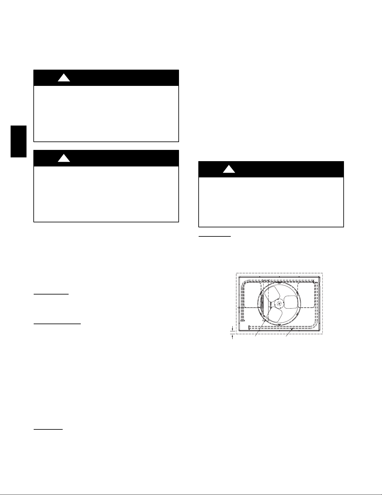
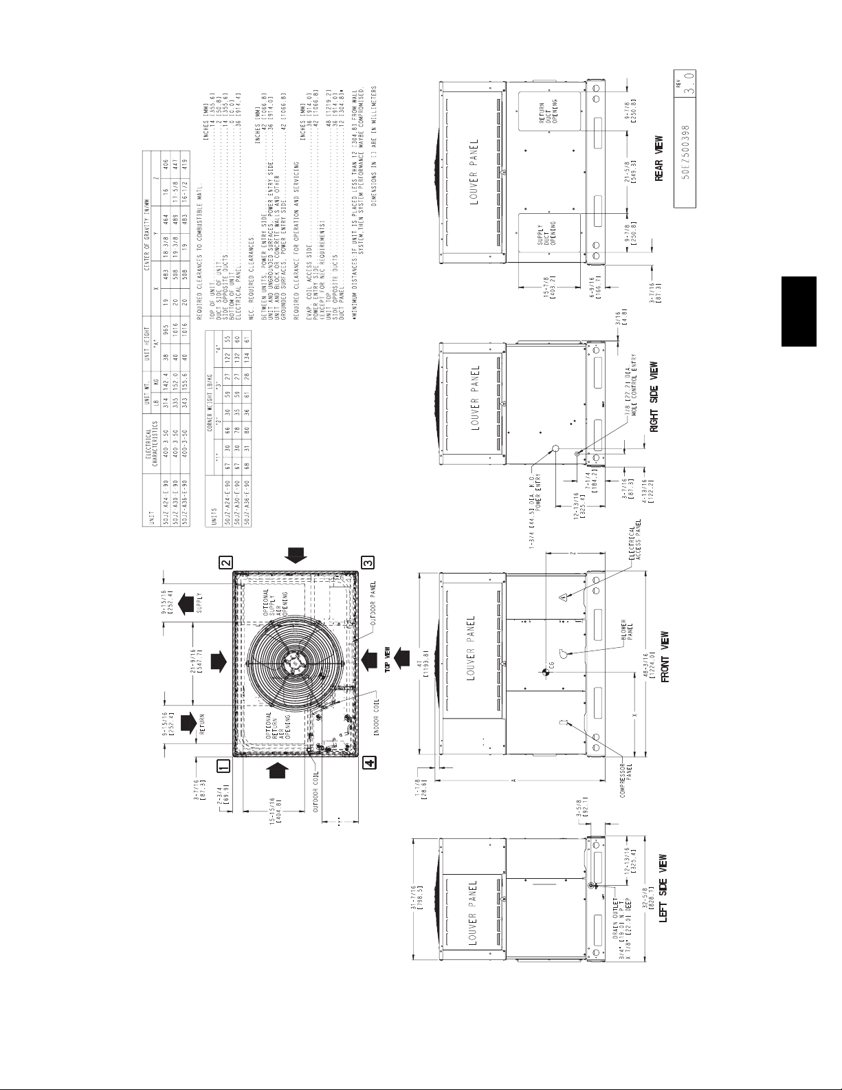
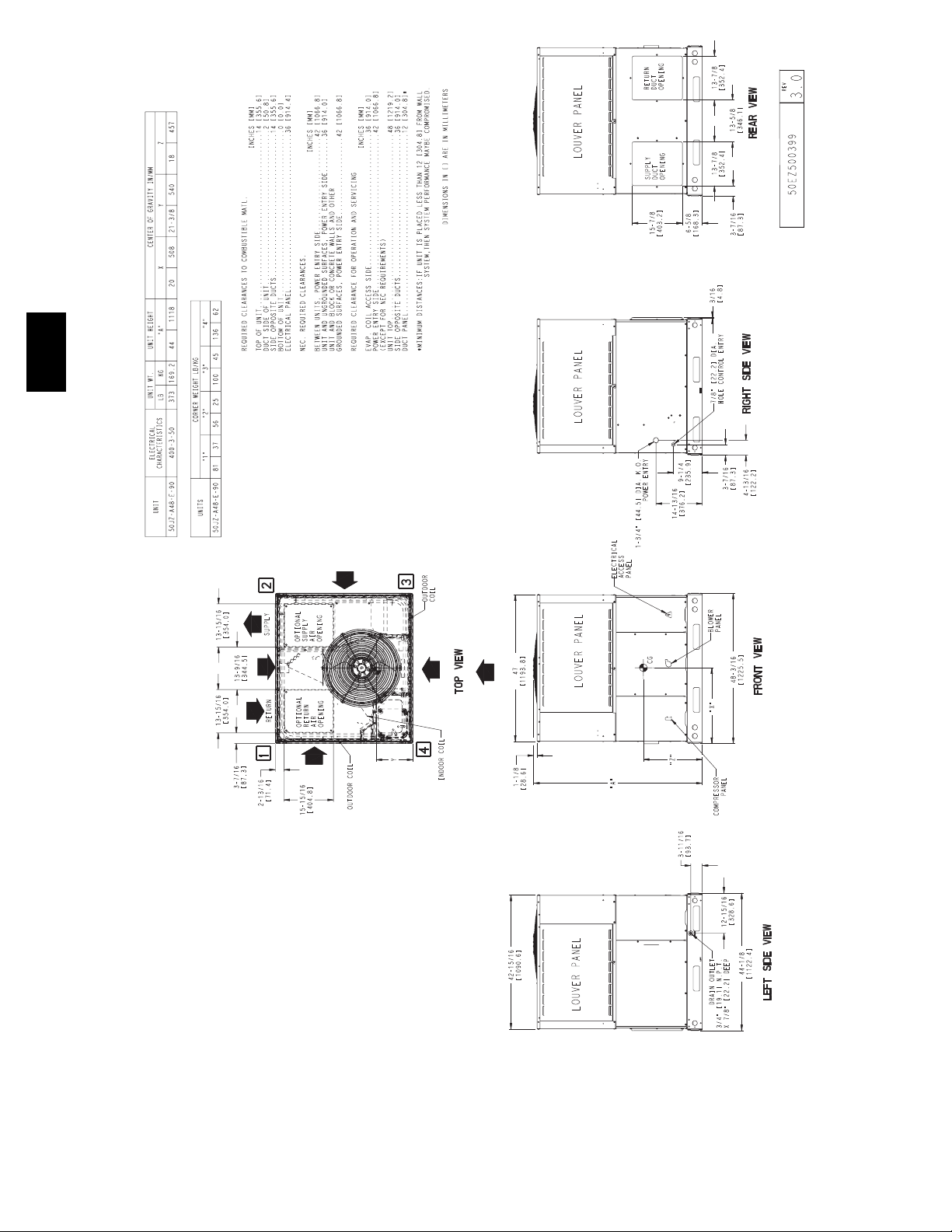
Step 3 — Provide Clearances
The required minimum service clearances are shown in Fig. 3 and
4. Adequate ventilation and outdoor air must be provided. The
outdoor fan draws air through the outdoor coil and discharges it
through the top fan grille. Be sure that the fan discharge does not
recirculate to the outdoor coil. Do not locate the unit in either a
corner or under an overhead obstruction. The minimum clearance
under a partial overhang (such as a normal house overhang) is 48
in. (1219 mm) above the unit top. The maximum horizontal
extension of a partial overhang must not exceed 48 in. (1219 mm).
IMPORTANT: Do not restrict outdoor airflow. An air restriction
at either the outdoor--air inlet or the fan discharge may be
detrimental to compressor life.
Do not place the unit where water, ice, or snow from an overhang
or roof will damage or flood the unit. Do not install the unit on
carpeting or other combustible materials. Slab--mounted units
2
should be at least 4 in. (102 mm) above the highest expected water
and runoff levels. Do not use unit if it has been under water.
50JZ-- A
Fig. 3 -- 50JZ--A24 --36 Unit Dimensions
3
A09502
50JZ-- A
Fig. 4 -- 50JZ--A48 Unit Dimensions
4
A09503
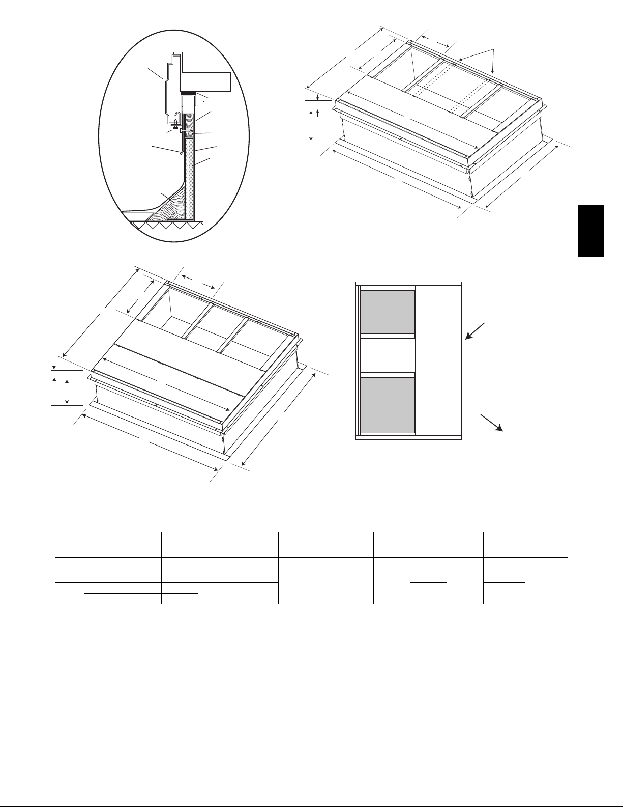
HVAC unit
base rails
Anchor screw
Flashing field
supplied
Roofing material
field supplied
Cant strip
field supplied
HVAC unit
basepan
Sealing
Gasket
Roofcurb
Wood nailer*
Roofcurb*
Insulation
(field supplied)
B
G
C
F
A
H
D
Dashed lines show cross support
location for large basepan units.
E
A09413
50JZ-- A
*Provided with roofcurb
ROOF CURB DETAIL
SMALL/COMMON CURB
A09090
B
C
G
A
F
H
E
SUPPLY
AIR
RETURN
AIR
SMALL
BASE
UNIT
LARGE
BASE
UNIT
D
UNIT PLACEMENT ON
LARGE CURB
A09415
COMMON CURB
SMALL OR LARGE BASE UNIT
A09094
A
UNIT
SIZE
Small
or
Large
Large
* Part Numbers CPRCURB010A00 and CPRCURB011A00 can be used on both small and large basepan units. T he cross supports must be located based on
whether the unit is a small basepan or a large basepan.
NOTES:
1. Roof curb must be set up for u nit being installed.
2. Seal strip must be applied, as required, to unit being installed.
3. Roof curb is made of 16 ---gauge steel.
4. Attach ductwork to curb (flanges of duct rest on curb).
5. Insulated panels: 1 --- in. (25 mm) thick fiberglass 1 lb. density.
CATALOG
NUMBER
IN.
(mm)
CPRFCURB010A00 11 (279)
CPRFCURB011A00 14 (356)
CPRFCURB012A00 11 (279)
CPRFCURB013A00 14 (356)
B (small/common
base)
IN. (mm)*
10 (254)
14 (356)
B (large base)
IN. (mm)*
14 (356) 16 (406)
C
IN.
(mm)
D
IN.
(mm)
47.8
(1214)
E
IN.
(mm)
32.4
(822)
43.9
(1116)
F
IN.
(mm)
2.7 (69)
G
IN. (mm)HIN. (mm)
30.6 (778)
42.2
(1072)
46.1
(1170)
Fig. 5 -- Roof Curb Dimensions
5
A09414
CAUTION - NOTICE TO RIGGERS
PRUDENCE - AVIS AUX MANIPULATEUR
PANNEAUX D'ACCES DOIT ÊTRE EN PLACE POUR MANIPULATION.
Use top skid as spreader bar. / Utiliser la palette du haut comme barre de répartition
ACCESS PANELS MUST BE IN PLACE WHEN RIGGING.
DUCTS
MINIMUM HEIGHT: 36" (914.4 mm)
HAUTEUR MINIMUM
50JZ-- A
SEE DETAIL A
VOIR DÉTAIL A
RIGGING WEIG HTS (SMALL CABINET) RIGGING WEIGHTS (LARGE CABINET)
Unit
Rigging Weight 314 142.4 335 152.0 343 155.6 Rigging Weight 373 169.2
NOTE: See dimensional drawing for corner weight distribution.
24 30 36
lb kg lb kg lb kg lb kg
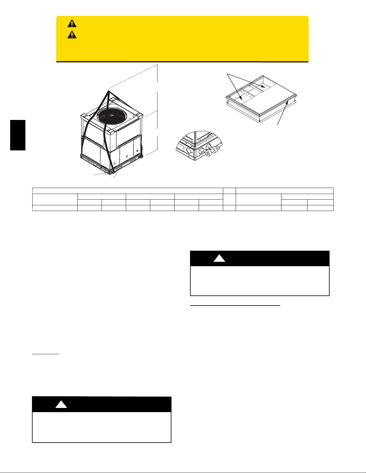
Step 4 — Rig and Place Unit
Rigging and handling of this equipment can be hazardous for
many reasons due to the installation location (roofs, elevated
structures, etc.).
Only trained, qualified crane operators and ground support staff
should handle and install this equipment.
When working with this equipment, observe precautions in the
literature, on tags, stickers, and labels attached to the equipment,
and any other safety precautions that might apply.
Training for operators of the lifting equipment should include, but
not be limited to, the following:
1. Application of the lifter to the load, and adjustment of the
lifts to adapt to various sizes or kinds of loads.
2. Instruction in any special operation or precaution.
3. Condition of the load as it relates to operation of the lifting
kit, such as balance, temperature, etc.
Follow all applicable safety codes. W ear safety shoes and work
gloves.
Inspection
Prior to initial use, and at monthly intervals, all rigging shackles,
clevis pins, and straps should be visually inspected for any damage,
evidence of wear, structural deformation, or cracks. Particular
attention should be paid to excessive wear at hoist hooking points
and load support areas. Materials showing any kind of wear in
these areas must not be used and should be discarded.
!
WARNING
UNIT FALLING HAZARD
Failure to follow this warning could result in personal
injury or death.
Never stand beneath rigged units or lift over people.
UNIT HEIGHT
HAUTEUR D'UNITÉ
DETAIL A
VOIR DÉTAIL A
Fig. 6 -- Rigging Weights
PROPERTY DAMAGE HAZARD
Failure to follow this warning could result in personal injury.
When straps are taut, the clevis should be a minimum of 36
in. (914 mm) above the unit top cover.
Rigging/Lifting of Unit (See Fig. 6)
Lifting holes are provided in base rails as shown.
After the unit is placed on the roof curb or mounting pad, remove
the top skid.
Step 5 — Select and Install Ductwork
The design and installation of the duct system must be in
accordance with the standards of the NFPA for installation of
non--residence type air conditioning and ventilating systems,
NFPA 90A or residence--type, NFPA 90B and/or local codes and
ordinances.
Select and size ductwork, supply--air registers, and return air grilles
according to ASHRAE (American Society of Heating,
Refrigeration, and Air Conditioning Engineers) recommendations.
The unit has duct flanges on the supply-- and return--air openings
on the side of the unit.
SEAL STRIP MUST BE IN
PLACE BEFORE PLACING
UNIT ON ROOF CURB
BANDE SCELLANT DOIT ÊTRE
EN PLACE AVANT DE PLACER
L'UNITÉ SUR LA BASE DE TOIT
50CY502286 2.0
Unit
A09051
48
1. Leave top shipping skid on the unit for use as a spreader bar
to prevent the rigging straps from damaging the unit. If the
skid is not available, use a spreader bar of sufficient length
to protect the unit from damage.
!
WARNING
1. Attach shackles, clevis pins, and straps to the base rails of
the unit. Be sure materials are rated to hold the weight of the
unit (See Fig. 6).
2. Attach a clevis of sufficient strength in the middle of the
straps. Adjust the clevis location to ensure unit is lifted level
with the ground.
6
!
WARNING
PERSONAL INJURY HAZARD
Failure to follow this warning could result in personal
injury or death.
For vertical supply and return units, tools or parts could
drop into ductwork Install a 90 degree turn in the return
ductwork between the unit and the conditioned space. If a
90 degree elbow cannot be installed, then a grille of
sufficient strength and density should be installed to prevent
objects from falling into the conditioned space. Units with
electric heaters require 90 degree elbow in supply duct.
When designing and installing ductwork, consider the following:
1. All units should have field-- supplied filters or accessory
filter rack installed in the return--air side of the unit.
Recommended sizes for filters are shown in Table 1.
2. Avoid abrupt duct size increases and reductions. Abrupt
change in duct size adversely affects air performance.
IMPORTANT: Use flexible connectors between ductwork and
unit to prevent transmission of vibration. Use suitable gaskets to
ensure weather tight and airtight seal. When electric heat is
installed, use fireproof canvas (or similar heat resistant material)
connector between ductwork and unit discharge connection. If
flexible duct is used, insert a sheet metal sleeve inside duct. Heat
resistant duct connector (or sheet metal sleeve) must extend 24--in.
(610 mm) from electric heater element.
3. Size ductwork for cooling air quantity (cfm). The minimum
air quantity for proper electric heater operation is listed in
Table 2. Heater limit switches may trip at air quantities
below those recommended.
4. Seal, insulate, and weatherproof all external ductwork. Seal,
insulate and cover with a vapor barrier all ductwork passing
through conditioned spaces. Follow latest Sheet Metal and
Air Conditioning Contractors National Association
(SMACNA) and Air Conditioning Contractors Association
(ACCA) minimum installation standards for residential
heating and air conditioning systems.
5. Secure all ducts to building structure. Flash, weatherproof,
and vibration--isolate duct openings in wall or roof
according to good construction practices.
CONFIGURING UNITS FOR DOWNFLOW
(VERTICAL)
DISCHARGE
shipped on unit from factory. Insure openings are air and
watertight.
NOTE: The design and installation of the duct system must be in
accordance with the standards of the NFPA for installation of
nonresidence--type air conditioning and ventilating systems, NFPA
90A or residence--type, NFPA 90B; and/or local codes and
ordinances.
Adhere to the following criteria when selecting, sizing, and
installing the duct system:
1. Units are shipped for side shot installation.
2. Select and size ductwork, supply--air registers, and
return--air grilles according to American Society of Heating,
Refrigeration and Air Conditioning Engineers (ASHRAE)
recommendations.
3. Use flexible transition between rigid ductwork and unit to
prevent transmission of vibration. The transition may be
screwed or bolted to duct flanges. Use suitable gaskets to
ensure weather--tight and airtight seal.
4. All units must have field--supplied filters or accessory filter
rack installed in the return--air side of the unit.
Recommended sizes for filters are shown in Table 1.
5. Size all ductwork for maximum required airflow (either
heating or cooling) for unit being installed. Avoid abrupt
duct size increases or decreases or performance may be
affected.
Horizontal Duct Covers
A09076
50JZ-- A
!
WARNING
ELECTRICAL SHOCK HAZARD
Failure to follow this warning could result in personal
injury or death.
Before performing service or maintenance operations on the
system, turn off main power to unit and install lockout tag.
1. Open all electrical disconnects and install lockout tag before
starting any service work.
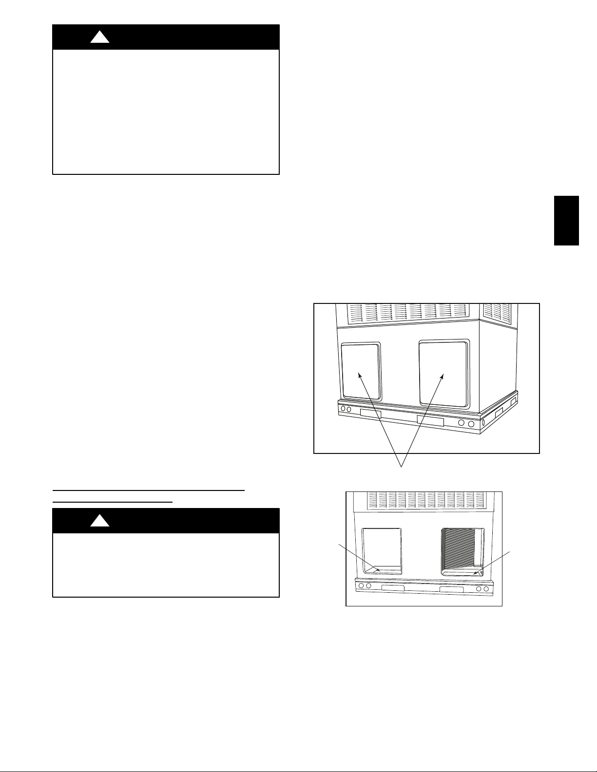
2. Remove horizontal (metal) ductcovers to access vertical
(downflow) discharge duct knockouts in unit basepan. (See
Fig. 7.)
3. To remove downflow return and supply knockout covers,
break front and right side connecting tabs with a
screwdriver and hammer. Push cover down to break rear
and left side tabs.
NOTE: These panels are held in place with tabs similar to an
electrical knockout. Reinstall horizontal duct covers (Fig. 7)
Basepan
Downflow
(Vertical)
Supply
Knockout
Fig. 7 -- Supply and Return Duct Opening
6. Adequately insulate and weatherproof all ductwork located
outdoors. Insulate ducts passing through unconditioned
space, and use vapor barrier in accordance with latest issue
of Sheet Metal and Air Conditioning Contractors National
Association (SMACNA) and Air Conditioning Contractors
of America (ACCA) minimum installation standards for
heating and air conditioning systems. Secure all ducts to
building structure.
7
Basepan
Downflow
(Vertical)
Return
Knockout
A09093
7. Flash, weatherproof, and vibration--isolate all openings in
A
building structure in accordance with local codes and good
building practices.
Step 6 — Provide for Condensate Disposal
NOTE: Ensure that condensate--water disposal methods comply
with local codes, restrictions, and practices.
The 50JZ--A units dispose of condensate through a 3/4 in. NPT
female fitting that exits on the compressor end of the unit.
Condensate water can be drained directly onto the roof in rooftop
installations (where permitted) or onto a gravel apron in ground
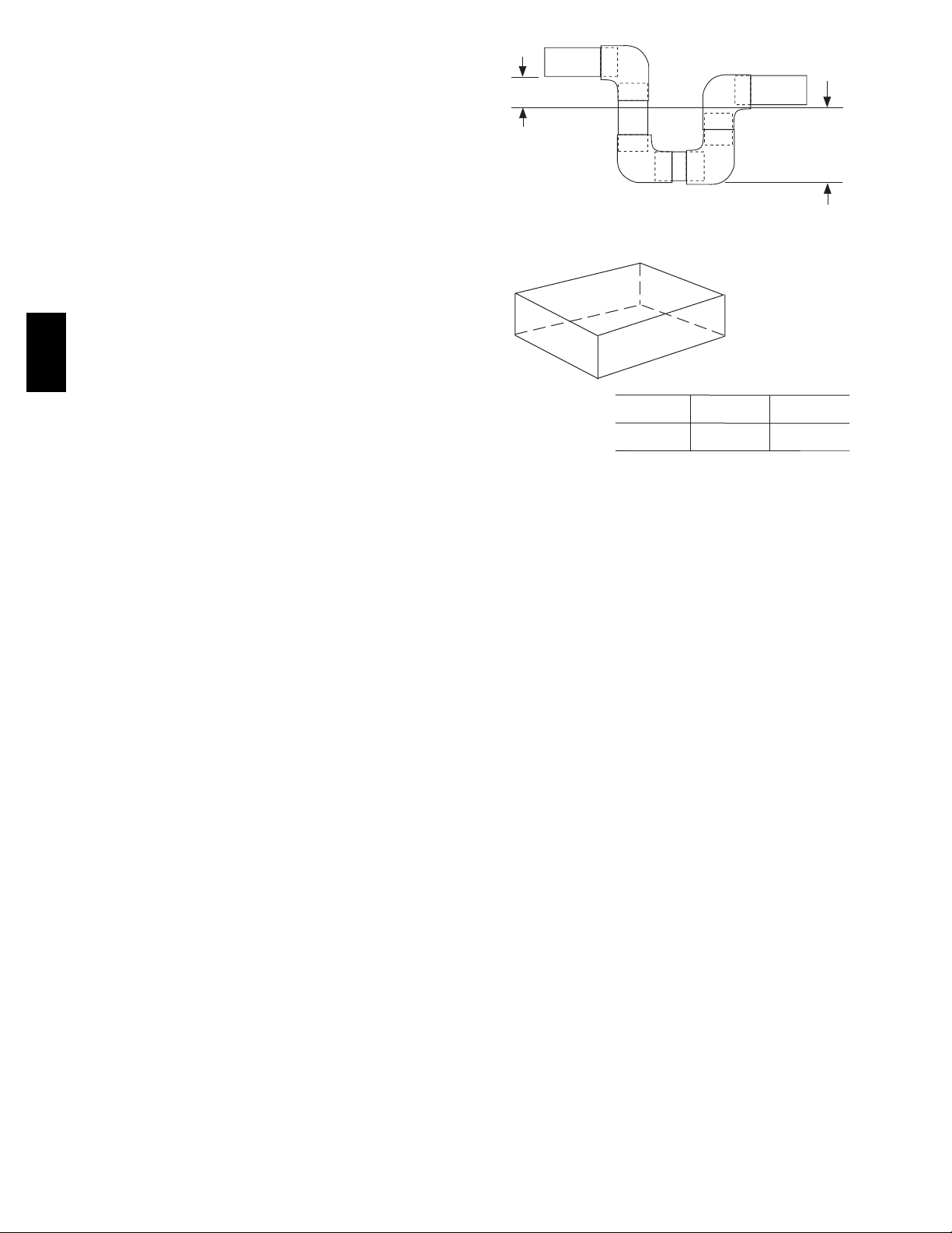
level installations. Install a field--supplied condensate trap at end of
condensate connection to ensure proper drainage. Make sure that
the outlet of the trap is at least 1 in. (25 mm) lower than the
drain--pan condensate connection to prevent the pan from
overflowing. Prime the trap with water. When using a gravel apron,
make sure it slopes away from the unit.
If the installation requires draining the condensate water away from
the unit, install a field--supplied 2 -- in. (51mm) trap at the
condensate connection to ensure proper drainage. Condensate trap
is available as an accessory or is field--supplied. Make sure that the
50JZ-- A
outlet of the trap is at least 1 in. (25 mm) lower than the unit
drain--pan condensate connection to prevent the pan from
overflowing. Connect a drain tube using a minimum of
field--supplied 3/4--in. PVC or field--supplied 3/4--in. copper pipe
at outlet end of the 2--in. (51 mm) trap. (See Fig. 8.) Do not
undersize the tube. Pitch the drain tube downward at a slope of at
least 1 in. (25 mm) every 10 ft (3 m) of horizontal run. Be sure to
check the drain trough for leaks. Prime the trap at the beginning of
the cooling season start--up.
1-in. (25 mm) min.
TRAP
OUTLET
Fig. 8 -- Condensate Trap
C
MAXIMUM ALLOWABLE
B
A-B
(6.35)
1/4
DIFFERENCE in. (mm)
B-C
(6.35)
1/4
Fig. 9 -- Unit Leveling Tolerances
2-in. (51 mm) min.
A09052
A-C
(6.35)
1/4
A07925
8
 Loading...