

Carrier 50JZ User Manual
Visit www.carrier.com
A Guide to Operating and Maintaining Your
Single-Packaged Electric Heat Pump Units
50JZ
Single-Packaged 50Hz, CE Electric Heat Pump Units
with Puron® (R-410A) Refrigerant
NOTE: Read the entire instruction manual before starting the
installation.
SAFETY CONSIDERATIONS
Note to Installer:This manual should be left with the equipment
user.
Do not store or use gasoline or other flammable vapors and
liquids in the vicinity of these or any other appliances. Failure
to follow this warning could result in fire, serious injury, or
death.
Do not use this unit if any part has been under water.
Immediately call a qualified service technician to inspect the
unit and to replace any part of the control system which has
been under water. Failure to follow this warning could result
in electrical shock, fire, serious injury, or death.
Before performing recommended maintenance, be sure the
main power switch to unit is turned off and lockout tag
installed. Electric shock could cause serious injury or death.
STARTING OR SHUTTING UNITS OFF
1. To start either of these units:
a. Turn on the electrical power supply to unit.
b. Select temperature and set SYSTEM switch or MODE
control to desired mode.
2. To shut this unit off:
NOTE: If the unit is being shut down because of a malfunction,
call your dealer as soon as possible.
a. Set system SWITCH or MODE control to OFF.
b. Turn off the electrical power supply to unit and install
lockout tag.
OPERATING YOUR HEAT PUMP
The operation of your heat pump system is controlled by the
indoor thermostat. You simply adjust the thermostat and it
maintains the indoor temperature at the level you select. Most
thermostats of heat pump systems have 3 controls: a temperature
control selector, a FAN control,andaSYSTEM or MODE control.
Refer to your thermostat owner’s manual for more information.
To better protect your investment and to eliminate unnecessary
service calls, familiarize yourself with the following facts:
1. During heating, increasing the thermostat setting more than
2°F/1.1°C may cause the supplemental heaters to be turned on
for a short period of time to satisfy the thermostat. Needless
use of the supplementary heat reduces potential energy savings.
2. Ice or frost tends to form on the coil during winter heating
operation. Your heat pump is designed to automatically melt
the ice. When in this defrost cycle, it is normal for steam or
fog to rise from the outdoor unit. Do not be alarmed!
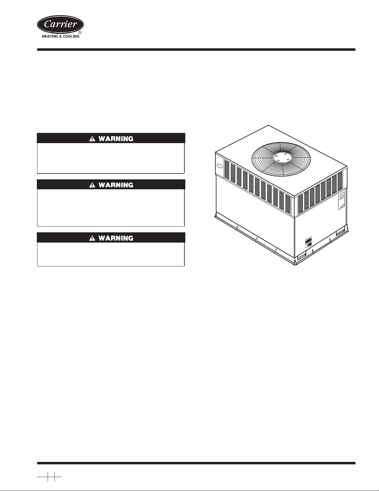
C990064
Fig. 1—Unit 50JZ (50Hz)
Step 1—Cooling Mode
With the SYSTEM or MODE control set to COOL, your heat
pump will run in cooling mode until the indoor temperature is
lowered to the level you have selected. On extremely hot days,
your heat pump will run for longer periods at a time and have
shorter “off” periods than on moderate days.
Step 2—Heating Mode
With the SYSTEM or MODE control of your indoor thermostat set
to HEAT, your heat pump will run in heating mode until room
temperature is raised to the level you have selected. Of course,
your heat pump will run for longer periods to maintain a
comfortable environment on cooler days and nights than on
moderate ones.
Step 3—Supplemental Heat
Your heat pump is your primary heating source. Your system may
also be equipped with a supplemental heating source such as
electric heat. On cold days and nights, your system will automatically turn on the supplemental heat in order to maintain the level
of comfort you have selected.
When your heat pump needs additional heat to keep you comfortable, your Carrier electronic thermostat will turn on the supplemental heat (if equipped) and display the “AUX HT” message.
Manufacturer reserves the right to discontinue, or change at any time, specifications or designs without notice and without incurring obligations.
Book 1 4
Tab 6a 8a
PC 101 Catalog No. 005–00009 Printed in U.S.A. Form OM50-C2 Pg 1 2–02 Replaces: New
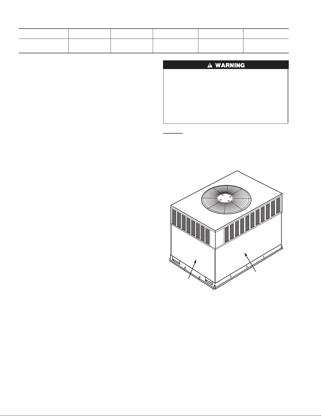
Table 1—Indoor-Air Filter Data
UNIT SIZE
50JZ (50HZ)
RETURN-AIR
FILTERS (mm.)
Throwaway
Step 4—Defrost Mode
When your heat pump is providing heat to your home or office and
the outdoor temperature drops below 45°F/7.2°C, moisture may
begin to freeze on the surface of the coil. If allowed to build up,
this ice would impede airflow across the coil and reduce the
amount of heat absorbed from the outside air. So, to maintain
energy-efficient operation, your heat pump has an automatic
defrost mode.
The defrost mode starts at a preset time interval of 30 minutes,
although, it may be reset to 60, 90 or 120 minutes. Defrost will
start at the preset time only if the ice is sufficient to interfere with
normal heating operation.
After the ice is melted from the coil, or after a maximum of 10
minutes in defrost mode, these units automatically switch back to
normal heating operation.
Do not be alarmed if steam or fog appears at the outdoor unit
during defrost mode. Water vapor from the melting ice may
condense into a mist in the cold outside air.
During certain weather conditions such as heavy snow and
freezing rain it is not uncommon for ice to build up on the unit
grille. This is normal for these weather conditions. Do not attempt
to remove the ice from the unit grille. This condition will not affect
the proper function of the unit and will clear within a few days.
Step 5—Emergency Heat Mode
This allows your supplemental heating source to keep your home
or office warm until your heat pump can be serviced.
MAINTENANCE AND SERVICE
This section discusses maintenance that should be performed by
your dealer and care you, as the owner, may wish to handle for
your new heat pump.
ROUTINE MAINTENANCE
All routine maintenance should be handled by skilled, experienced
personnel. Your dealer can help you establish a standard procedure.
For your safety, keep your unit area clear and free of combustible
materials, gasoline, and other flammable liquids and vapors.
To assure proper functioning of your unit, flow of condenser air
must not be obstructed from reaching the unit. Minimum clearance
from the top of the unit is 48 in./1219 mm. Clearance of at least 36
in./914 mm is required on sides except the power entry side (42
in./1067 mm clearance) and the duct side (12 in./305 mm minimum clearance).
MAINTENANCE AND CARE FOR THE EQUIPMENT
OWNER
Before proceeding with those things you might want to maintain
yourself, please carefully consider the following:
024 030 036 048 060
20” x 20”
(508 x 508)
20” x 20”
(508 x 508)
20” x 24”
(508 x 609.6)
24” x 30”
(609.6 x 762)
24” x 30”
(609.6 x 762)
1. TURN OFF ELECTRICAL POWER TO YOUR UNIT
BEFORE SERVICING OR PERFORMING MAINTENANCE. ELECTRIC SHOCK COULD CAUSE SERIOUS INJURY OR DEATH.
2. When removing access panels or performing maintenance
functions inside your unit, be aware of sharp sheet metal
parts and screws. Although special care is taken to keep
sharp edges to a minimum, be extremely careful when
handling parts or reaching into the unit.
Air Filters
The air filter(s) should be checked at least every 3 or 4 weeks and
changed or cleaned whenever it becomes dirty. Dirty filters
produce excessive stress on the blower motor and can cause the
motor to overheat and shut down. Table 1 indicates the correct
filter size for your unit. Refer to Fig. 2 to access the filters.
ACCESS PANEL
FILTER ACCESS
PANEL*
*For accessory filter rack.
Fig. 2—Filter Access Panel-Vertical Supply Shown
To replace or inspect filters (or accessory filter rack when
supplied):
1. Remove the filter access panel using a 5/16-in. (7.9 mm) nut
driver or wrench.
2. Remove the filter(s) by pulling it out of the unit. If the filter(s)
is dirty, clean or replace with a new one.
When installing the new filter(s), note the direction of the airflow
arrows on the filter frame.
If you have difficulty locating your air filter(s) or have questions
concerning proper filter maintenance, contact your dealer for
instructions. When replacing filters, always use the same size and
type of filter that was supplied, originally, by the installer.
2
C99094
 Loading...