

Page 1

Single-Package Rooftop Units
Electric Cooling/Gas Heating
Installation, Start-Up and
Service Instructions
48TJ016-028
CONTENTS
Page
SAFETY CONSIDERATIONS............................................I
INSTALLATION.............................................................2-31
Step 1 — Provide Unit Support............................................2
• ROOF CURB
• ALTERNATE UNIT SUPPORT
Step 2 —- Rig and Place Unit
• POSITIONING
• ROOF MOUNT
Step 3 — Field Fabricate Ductwork.....................................9
Step 4 — Make Unit Duct Connections
Step 5 — Install Flue Hood and Wind Baffle
Step 6 — Trap Condensate Drain........................................9
Step 7 — Orifice Change
Step 8 — Install Gas Piping
Step 9 — Make Electrical Connections
• FIELD POWER SUPPLY
• FIELD CONTROL WIRING
• OPTIONAL NON-FUSED DISCONNECT
• OPTIONAL CONVENIENCE OUTLET
Step 10 — Make Outdoor-Air Inlet Adjustments,. 14
Step 11 — Install Outdoor-Air Hood
Step 12 — Install All Accessories.......................................15
MOTORMASTER® I CONTROL INSTALLATION
MOTORMASTER V CONTROL INSTALLATION
Step 13 — Adjust Factory-Installed Options
PREMIERLINKTM CONTROL
ENTHALPY SWITCH/RECEIVER
OUTDOOR ENTHALPY CONTROL
DIFFERENTIAL ENTHALPY CONTROL
ENTHALPY SENSORS AND CONTROL
OPTIONAL ECONOMISERIV AND
ECONOMI$ER2
ECONOMI$ERIV STANDARD SENSORS
ECONOMI$ERIV CONTROL MODES
Step 14 — Install Humidlstat for
Optional MoistureMISer’'“ Package
START-UP......................................................................31-38
SERVICE........................................................................39-47
TROUBLESHOOTING
INDEX...................................................................................53
START-UP CHECKLIST..............................................CL 1
...............................................
...............................
.....................
....................................................
................................................
.............................
................................
....................
............................
................................................
10
11
11
14
17
29
48 52
precautions in the literature, tags and labels attached to the unit,
and other safety precautions that may apply.
Follow all siifety codes. Wear safety glasses and work
gloves. Use quenching cloth for unbrazing operations. Have
fire extinguishers available for till brazing operations.
A WARNING
2
9
9
Before performing service or maintenance operations on
unit, turn off main power switch to unit. Electrical shock
could cause personal injuiy.
A WARNING
1. Improper instiillation, adjustment, alteration, service,
or maintenance can cause properfy ckimage, personal
injuiy, or loss of life. Refer to the User's Information
Manual provided with this unit for more details.
2, Do not store or use gasoline or other flammable
vapors and liquids in the vicinity of tliis or any otlier
appliance.
What to do if you smell gas:
1. DO NOT tiy to light any appliance.
2. DO NOT touch any electrical switch, or use any
phone in your building,
3. IMMEDIATELY call your gas supplier from a neigh
bor’s phone. Follow the gas supplier’s instmctions.
4. If you cannot reach your gas supplier, cttll the fire
deparfment.
A WARNING
Disconnect gas piping from unit when pressure testing at
pressure greater than 0.5 psig. Pressures greater than
0.5 psig will cause gas valve damage resulting in haziu'dous
condition. If gas valve is subjected to pressure greater than
0.5 psig, it must be replaced before use. When pressure
testing field-supplied gas piping at pressures of 0.5 psig or
less, a unit connected to such piping must be isolated by
closing the manual gas valve(s).
SAFETY CONSIDERATIONS
Installation and seiTicing of air-conditioning equipment can
be hazardous due to system pressure and electrictil compo
nents, Only triiined and qualified service personnel should in
stall, repair, or service air-conditioning equipment.
Untrained personnel can perform basic maintenance func
tions of cleaning coils and filters and replacing filters. All other
operations should be performed by trained service personnel.
When working on air-conditioning equipment, observe
Manufacturer reserves the right to discontinue, or change at any time, specifications or designs without notice and without incurring obligations.
Book 1 |4
Tab lajca
Catalog No. 04-53480009-01 Printed in U.S.A. Form 48TJ-22SI Pg 1 3-06 Replaces: 48TJ-21SI
IMPORTANT: Units have high ambient operating lim
its. If limits are exceeded, the units will automatically
lock the compressor out of operation. Manuiil reset will
be required to restiuf the compressor.
Page 2
INSTALLATION
Inspect unit for transportation danage. If cktmage is found,
file claim with transportation agency.
Step 1 — Provide Unit Support
ROOF CURB — Assemble and install accessoiy roof curb or
horizontiil adapter roof cuifi in accordance witli instinctions
shipped with this accessoiy. See Fig. 1 and 2. Install insulation,
cant strips, roofing, and counter flashing as shown. Ductwork
can be installed to roof curb or horizontal adapter roof curb be
fore unit is set in place. Curb or adapter roof curb should be
level. Tills is necessaiy to permit unit drain to function proper
ly. Unit leveling tolerance is ± Vu, in. per linear ft in any direc
tion. Refer to Accessoiy Roof Curb or Horizontal Adapter
Roof Curb Installation Instmctions for additional information
as required. When accessoiy roof curb or horizontal adapter
roof curb is used, unit may be installed on class A, B, or C roof
covering material.
IMPORTANT: The gasketing of the unit to the roof curb
or adapter roof curb is critical for a watertight setil.
InstiJI gasket with the roof curb or adapter as shown in
Fig. 2. Improperly applied gasket can also result in air
leaks and poor unit performance.
ALTERNATE UNIT SUPPORT ^ When the curb or adapter
cannot be used, install unit on a noncombustible surface. Sup
port unit with sleepers, using unit curb support area. If sleepers
cannot be used, support long sides of unit with a minimum of 3
equally spaced 4-in. x 4-in. pads on each side.
Step 2 — Rig and Place Unit — Do not di'op unit;
keep upright. Use spreader biu's over unit to prevent sling or
cable diimage. Rollers may be used to move unit across a roof.
Level by using unit frame as a reference; leveling tolerance is
±V](i in. per linear ft in any direction. See Fig. 3 for additional
information. Unit operating weight is shown in Table 1.
Four lifting holes are provided in ends of unit base rails as
shown in Fig. 3. Refer to rigging instmctions on unit.
POSITIONING — Maintain clearance, per Fig. 4 and 5,
around and above unit to provide minimum distance from
combustible materials, proper airflow, and service access.
Do not install unit in an indoor location. Do not locate unit
air inlets near exhaust vents or other sources of contaminated
air. For proper unit operation, adequate combustion and venti
lation ail' must be provided in accordance with Section 5.3 (Air
for Combustion and Ventilation) of the National Fuel Gas
Code, ANSI Z223.1 (American National Standards Institute).
Although unit is weatlierproof, guard against water from
higher level mnoff and overhangs.
Locate mechanical di'aft system flue assembly at least 4 ft
from any opening through which combustion products could
enter the building, and at least 4 ft from any adjacent building.
When unit is located adjacent to public walkways, flue assem
bly must be at least 7 ft above grade.
ROOF MOUNT — Check building codes for weight distri
bution requirements. Unit operating weight is shown in
Table 1.
Instructions continued cm page 9.
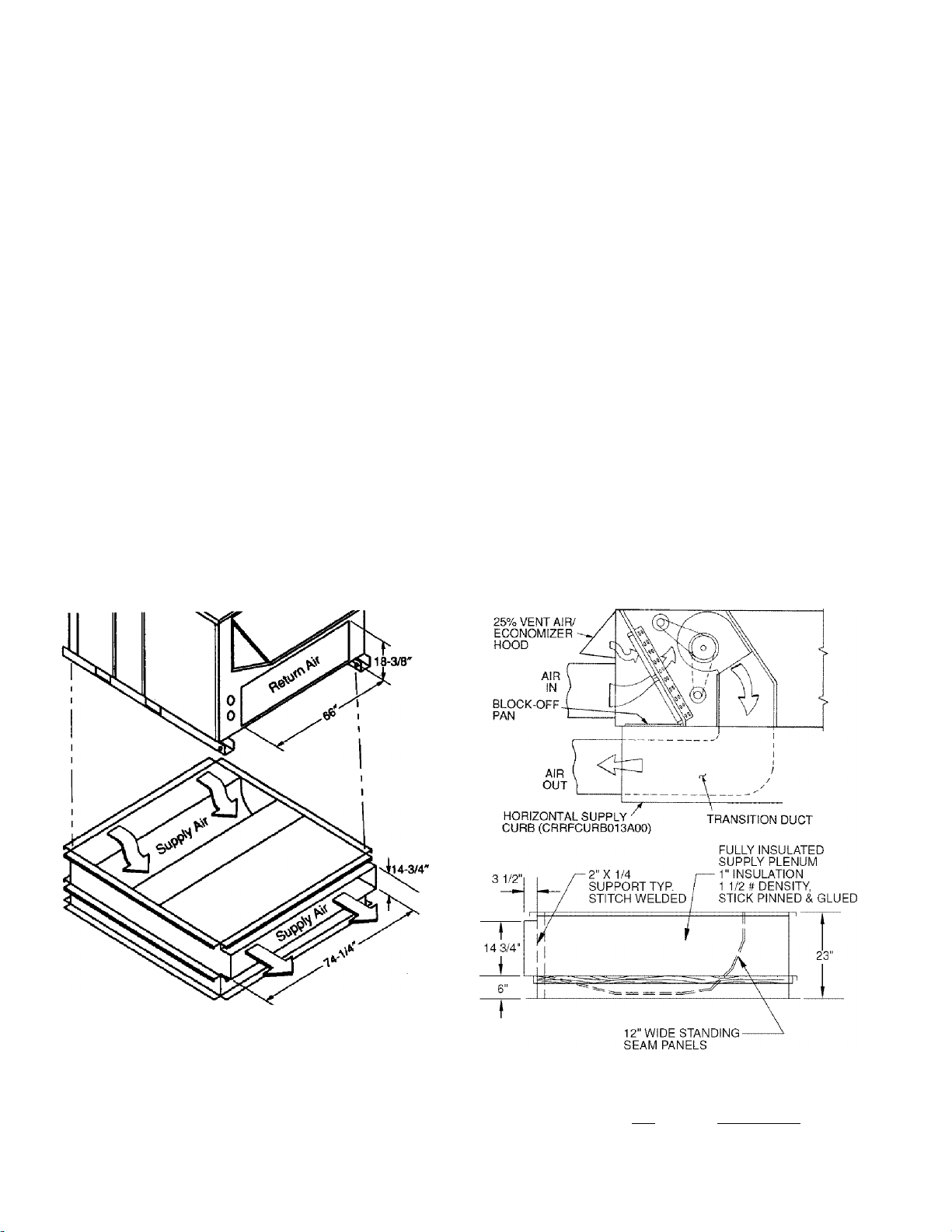
NOTE: CRRFCURB013A00 is a fuliy factory prsassembied hori
zontal adapter and includes an insulated transition duct. The pres
sure drop through the adapter curb is negligible.
For horizontal return applications; The power exhaust and baro
metric relief dampers must be installed in the return air duct.
Fig. 1 — Horizontal Supply/Return Adapter Installation
ACCESSORY
PACKAGE NO.
CRRFCURB013AOO
CURB
HEIGHT
(584)
DESCRIPTION
Pre-Assembled, Roof Curb,
Horizontal Adapter
Page 3
PKG. NO. REF.
CURB
HEIGHT
DESCRIPTION
CRRFCURB010A00 2" (305) Standard Curb 14" High
CRRFCURB011A00 2'- 0"(610) Standard Curb for Units Requiring High Installation
CRRFCURB012A00 2'- 0"(610) Side Supply and Return Curb for High Installation
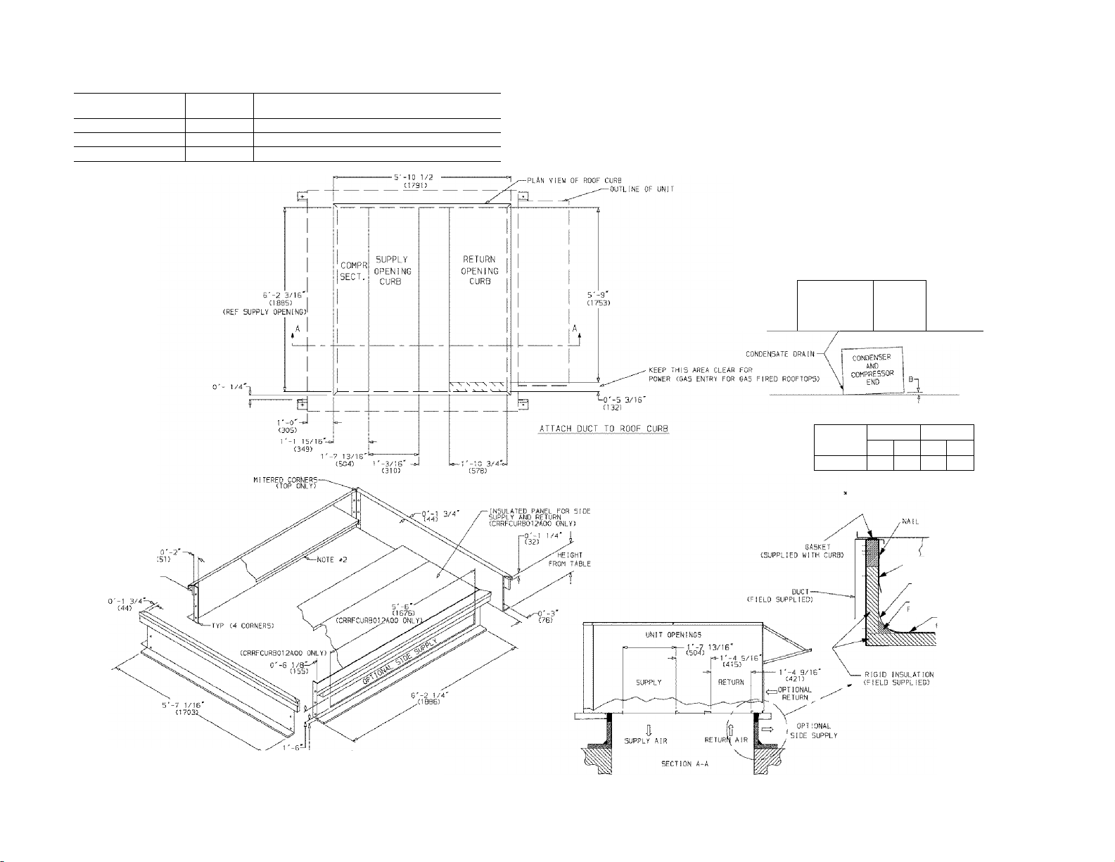
NOTES:
K ROOF CURB ACCESSORY 15 SHIPPED D15AS5EHBLED.
2. INSULATED PANELS: 1* THICK NEOPRENE COATED 1-1/2 LB DENSITY
3. DIMENSIONS IN C ) ARE IN MILLIMETERS.
4. c=i> direction of AIR FLOW
5. ROOFCURB: 16 GA. CVA03-56) STL.
S. A 30 DEGREE ELBOW MUST BE INSTALLED ON THE SUPPLY DUCT
WORK BELOW THE UNIT DISCHARGE FOR UNITS EQUIPPED WITH
ELECTRIC HEATERS.
NOTE;
TO PREVENT THE HAZARD OF STAGNANT WATER
BUllD-UP IN THE DRAIN PAN OF THE INDOOP
SECTION, UNIT CAN ONLY BE PITCHED AS SHOWN.
....
.
UNIT
ALL .26 .45 .28 .43
CONDENSER
AND
COMPRESSOR
END
DIMENSIONS (degrees ond inches)
A
DEG. IN. DEG. IN.
UNIT LEVELING TOLERANCES
-nom edge oF unit to horizcntoL.
B
A-
NOM. 5/4 K
(323 X (1023
TYP. 4 PLC5
COUNTER FLASHING;
A
CRRFCURB012A00'0NLY) 0
<CRRFCURB012AOO ONLY)
(FIELD SUPPLIED)
•ROOFING FELT
(FIELD SUPPLIED)
■CANT STRIP
(FIELD SUPPLIED)
ROOFING MATERIAL
(FIELD SUPPLIED)
Fig. 2 — Roof Curb Details
Page 4
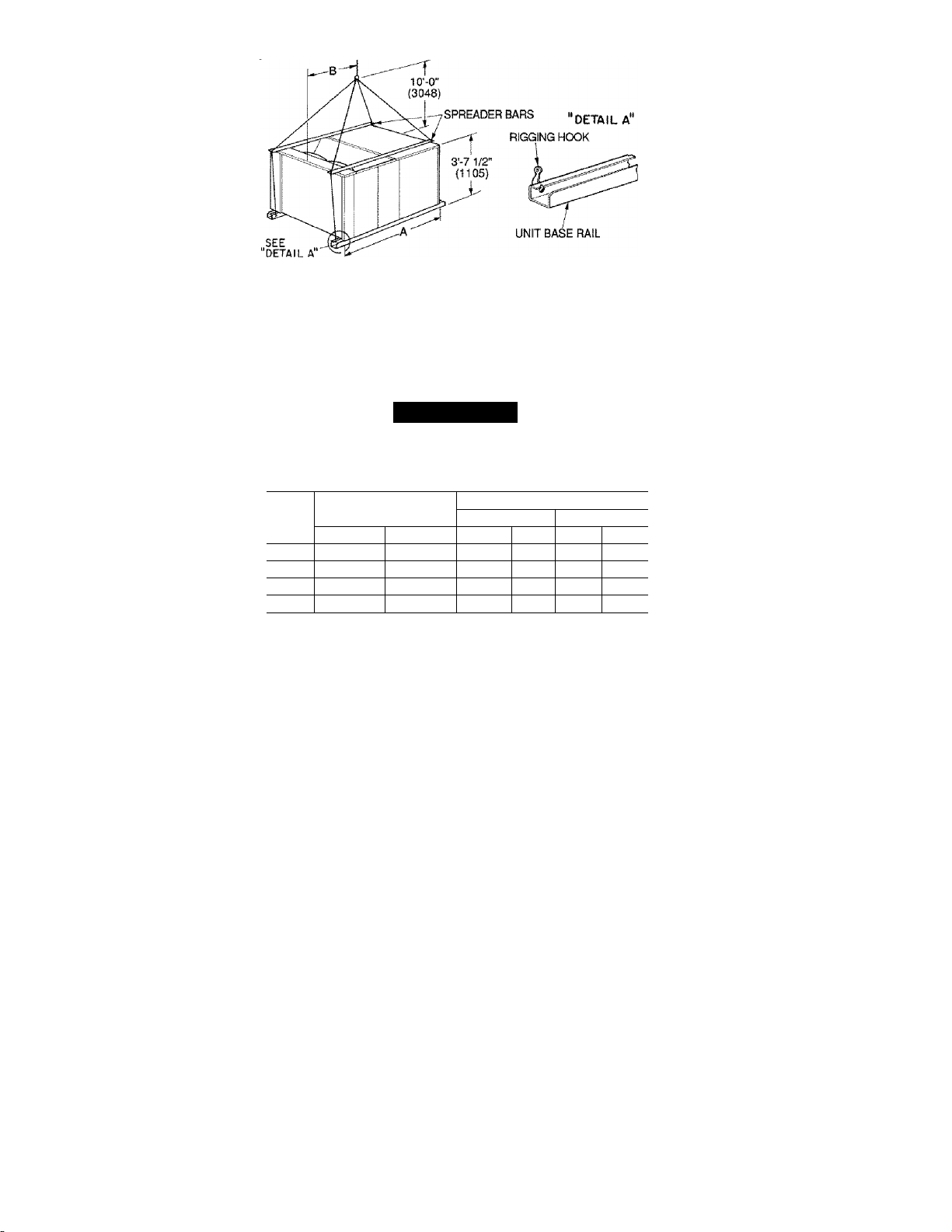
NOTES;
1. Dimensions in ( ) are in millimeters.
2. Refer to Fig. 4 and 5 for unit operating weights.
3. Remove boards at ends of unit and runners prior to rigging.
4. Rig by inserting hooks into unit base rails as shown. Use corner post from packaging to protect coil from
damage. Use bumper boards for spreader bars on all units.
5. Weights do not include optional economizer. Add 90 lb (41 kg) for economizer weight.
6. Weights given are for aluminum evaporator and condenser coil plate fins.
A CAUTION
All panels must be in place when rigging.
UNIT
48TJ
016 1775 805
020 1875 850 6-11 Vg 2121 3-3 991
024 1985 900
028 2135 968 6-11 Vg 2121 3-2 965
MAXIMUM
SHIPPING WEIGHT
lb kg Ft-in. mm Ft-in. mm
6-11V2
6-11 Vg
DIMENSIONS
A B
2121 3-5 1041
2121 3-2 965
Fig. 3 — Rigging Detaiis
Page 5
HP m PLCS
0 ' ■ 3 T3S“^ Í
1993 I
STD UNIT
WEIGHT
UNIT
lb
48TJD,
1650 748 90 41 423 192 386 175 403 183 438 199 3-5 1041 3-5 1041 1-10 559
TJF016
48TJD,
1800 816 90 41 432 196 410 186 461 209 472 214 3-3 991 3-7 1092 1-8 508
TJF020
ECONOMIZER
kg
WEIGHT
lb
CORNERACORNERBCORNERCCORNER
lb
kg
lb
kg
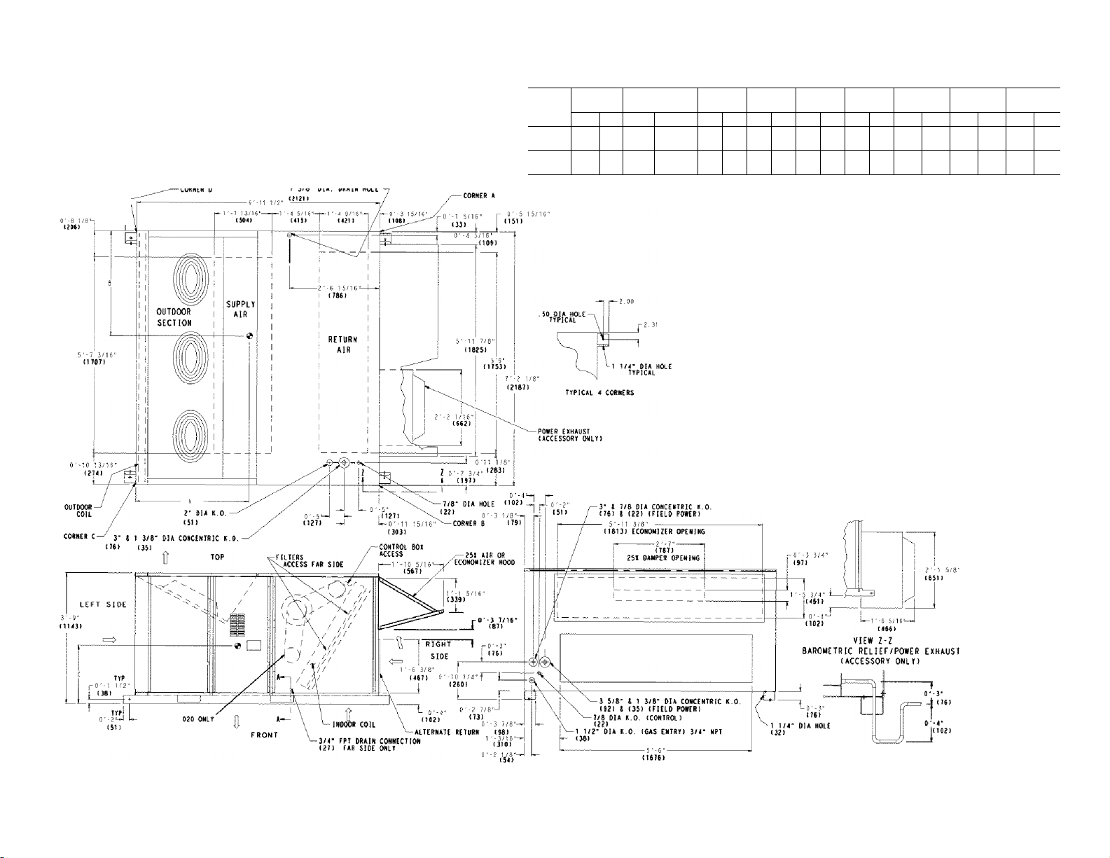
NOTES:
1. Refer to print for roof curb accessory dimensions.
2. Dimensions in ( ) are in miiiimeters.
o Direction of airflow.
5. Ductwork to be attached to accessory roof curb only.
6. Minimum clearance:
• Rear: 7'-0" (2134) for coil removal. This dimension can be reduced to
4'-0" (1219) if conditions permit coil removal from the top.
• 4'-0" (1219) to combustible surfaces, all four sides (includes between
units).
• Left side; 4'-0" (1219) for proper condenser coil airflow.
• Front: 4'-0" (1219) for control box access.
• Right side: 4'-0" (1219) for proper operation of damper and power
exhaust if so equipped.
• Top: 6'-0" (1829) to assure proper condenser fan operation.
• Bottom: 14" (356) to combustible surfaces (when not using curb).
• Control box side; 3'-0" (914) to ungrounded surfaces, non-combustible.
• Control box side: 3'-6" (1067) to block or concrete walls, or other
grounded surfaces.
• Local codes or jurisdiction may prevail.
7. With the exception of clearance for the condenser coil and the damper/
power exhaust as stated in Note #6, a removable fence or barricade
requires no clearance.
8. Dimensions are from outside of corner post. Allow O'-s/ie" (8) on each side
for top cover drip edge.
lb
kg
Center of Gravity,
D
lb
kg
DIMA DIM B DIM C
ft-in. mm ft-in. mm ft-in. mm
kg
Fig. 4— Base Unit Dimensions; 48TJ016,020
SECTION A-A
Page 6
TTP (41 PLCS^
0'-3 ?/8'
1 3/8* 8iA. 08AIM HOLE
STD UNIT
WEIGHT
UNIT
lb
48TJD,
1850 839 90 41 443 201 406 184 476 216 525 238 3-2 965 3-5 1041 1-8 508
TJF024
48TJD,
2000 907 90 41 471 214 428 194 526 239 574 260 3-2 965 3-5 1041 1-8 508
TJF028
ECONOMIZER
lb
kg
WEIGHT
CORNERACORNERBCORNERCCORNER
lb
kg
lb
kg
NOTES:
1. Refer to print for roof curb accessory dimensions.
2, Dimensions in ( ) are in millimeters.
3^ Center of Gravity.
5. Ductwork to be attached to accessory roof curb only.
6. Minimum clearance:
• Rear: 7'-0" (2134) for coil removal. This dimension can be reduced to
4'-0" (1219) if conditions permit coil removal from the top.
• 4'-0" (1219) to combustible surfaces, all four sides (includes between
units).
' Left side: 4'-0" (1219) for proper condenser coil airflow.
' Front: 4'-0" (1219) for control box access.
• Right side: 4'-0" (1219) for proper operation of damper and power
exhaust if so equipped.
• Top: 6'-0" (1829) to assure proper condenser fan operation.
' Bottom: 14" (356) to combustible surfaces (when not using curb).
' Control box side: 3'-0" (914) to ungrounded surfaces, non-combustible.
• Control box side: 3'-6" (1067) to block or concrete walls, or other
grounded surfaces.
• Local codes or jurisdiction may prevail.
7. With the exception of clearance for the condenser coil and the damper/
power exhaust as stated in Note #6, a removable fence or barricade
requires no clearance.
8. Dimensions are from outside of corner post. Allow O'-^/ie" (8) on each
side for top cover drip edge.
lb
kg
Direction of airflow.
DIMA DIM B DIMC
D
lb
kg
ft-in. mm ft-in. mm tt-in. mm
kg
Fig. 5 — Base Unit Dimensions; 48TJ024,028
SECTfON A-A
Page 7

Table 1 — Physical Data
UNIT 48TJ
208/230, 460 V 1 575 V
NOMINAL CAPACITY (tons) 15 18 20 25
OPERATING WEIGHT (lb)
Economizer
Roof Curb
COMPRESSOR
Quantity...Model (Ckt 1, Ckt 2)
Number of Refrigerant Circuits
Oi!(oz)(Ckt1,Ckt 2)
Stages of Capacity Controi (%)
REFRiGERANTTYPE
Expansion Device
Operating Charge (Ib-oz)
Circuit 1*
Circuit 2
CONDENSER COIL
Rows...Fins/in.
Total Face Area (sq ft)
CONDENSER FAN
Nominal Cfm
Quantity...Diameter (in.)
Motor Hp...Rpm
Watts Input (Total)
EVAPORATOR COIL
Rows...Fins/in.
Total Face Area (sq ft)
EVAPORATOR FAM Centrifugal Type
Quantity...Size (in.) 2...10 X 10 2...10 X 10 2...12X 12 2...12 X 12 2...12X 12
Type Drive Belt Belt Belt Belt Belt
Nominal Cfm 6000 6000 7200 8000 10,000
Motor Hp 3.7 3.0 5 7.5 10
Motor Nominal Rpm 1725 1725 1745 1745 1740
Maximum Continuous Bhp 4.25 3.45 5.90
Motor Frame Size 56H 56H 184T 213T 215T
Nominal Rpm High/Low
Fan r/s Range Low-Medium Static 891-1179 1159-1429 910-1095 1002-1225 1066-1283
Motor Bearing Type Ball Ball Ball Ball Ball
Maximum Allowable Rpm 1550 1550 1550 1550 1550
Motor Pulley Pitch Diameter Low-Medium Static 3.1/4.1 4.3/5,3 4.9/5.9 5.4/6.6 4,9/5.9
Min/Max (in.) High Static 3.7/4.7
Nomina! Motor Shaft Diameter (in.)
Fan Pulley Pitch Diameter (in.) Low-Medium Static 6.0 6.4 9.4 9.4 8.0
Nominal Fan Shaft Diameter (in.)
Belt, Quantity..,Type...Length (in.) Low-Medium Static 1...BX...42 1...BX...45 1...BX...50 1...BX...54 2...BX...50
Pulley Center Line Distance (in.) 13.5-15,5 13.5-15,5 13.3-14.8 14.6-15.4 14,6-15.4
Speed Change per Full Turn of Low-Medium Static 48 44 37 37 36
Movable Pulley Flange (rpm)
Movable Pulley Maximum Full Turns
From Closed Position 5 5 5 5 5
Factory Speed 3.5 3,5 3.5 3.5 3.5
Factory Speed Setting (rpm) Low-Medium Static 1035 1296 1002 1120 1182
Fan Shaft Diameter at Pulley (in.)
LEGEND
Bhp ™ Brake Horsepower
TXV — Thermostatic Expansion Valve
Xircuit 1 uses the lower portion of condenser coil and lower portion of evap
orator coils; and Circuit 2 uses the upper portion of both coils.
fRollout switch is manual reset.
High Static 1227-1550
High Static 5.2
High Static 1...BX...42
High Static 55
High Static 1389
016D/F
1650
90
200
2...SR’'942AE
2
90, 90
50/50
10-13 1 15-2 1 16-3 1 21-0
10-5 1 11-5 1 14-8 1 15-4
Cross-Hatched %-in. Copper Tubes, Aluminum Lanced,
2.,.17 1 3...15 1 3...15 I 4.,,15
21.7 1 21.7 1 21.7 1 21.7
10,400
3.. .22
f/2..,1050
1100
2...17 I 3...15 I 3...15 I
17.5 17.5 17.5
— — — — —
% Vh
1"/,6 13/16 1"/16 1"/i6
1"/i6 13/16 1^16 1 Vi 6 1 Vi6
Aluminum Pre-Coated, or Copper Plate Fins
Cross-Hatched ^/a-in. Copper Tubes, Aluminum Lanced or
—
_
—
—
—
—
"'"'The 48TJ028 units requires 2-in. industrial-grade filters capable of handling
face velocities of up to 625 ft/min {such as American Air Filter no. 5700 or
equivalent).
NOTE: The 48TJ016-028 units have a low-pressure switch (standard) located
on the suction side.
020D/F 024D/F 028D/F
1B00
90
200
Scr
1...SM120,
1...SRV82AE
2
110, 72
60/40
R-22
TXV
Propelle
9300
3...22
'/г...1050
1100
Copper Plate Fins, Face Split
1069-1287 1193-1458 1332-1550
4.9/5.9 5.4/6.6 4,9/5.9
1'/8 1% 13/8
8.0 7.9 6.4
1...BX...48 1..,BX,..50 2..,BX,..47
34 44 45
1178 1328 1470
1850
90
3ll
200
1.. .5M120,
1.. .5M110
2
110,110
52/48
r Type
13,700
2,,.30
1..,1075
3400
8.7 [208/230, 575 v]
9.5 [460 v[
1.. .5M161,
1.. .5M120
10.2 [208/230, 575 v[
11.8 [460 v]
2000
90
200
2
112, 110
56/44
12,500
2...30
1.,.1075
3400
4...15
17.5
1Vi6
Page 8

Table 1 — Physical Data (cent)
FURNACE SECTION
Rollout Switch Cutout Temp (F)+ 190 190 190 190
Burner Orifice Diameter (in....drill size)
Natural Gas 0.1285...30/0.136...29 0.1285...30/0.136...29 0.1285...30/0.136...29 0.1285...30/0.136...29
Thermostat Heat Anticipator Setting (amps)
208/230, 575 Stage 1 0.98 0.98 0.98 0.98
460 V stage 1 0.80 0.80 0.80 0,80
Gas Input Stage 1 172,000/225,000 206,000/270,000 206,000/270,000 206,000/270,000
Efficiency (Steady State) {%) 81 81 81 81
Temperature Rise Range
Manifold Pressure (in. wg)
Natural Gas 3.3 3.3 3.3 3.3
Gas Valve Quantity 1 1 1 1
Field Gas Connection Size (in .-FPT)
HIGH-PRESSURE SWITCH (psig)
Cutout
Reset (Auto)
LOW-PRESSURE SWITCH (psig)
Cutout
Reset (Auto)
FREEZE PROTECTION THERMOSTAT (F)
Opens
Closes
OUTDOOR-AIR INLET SCREENS
Quantity...Size (in.)
RETURN-AIR FILTERS
Quantity...Size (in.)
POWER EXHAUST V2 Hp, 208/230-460 V Motor Direct Drive, Propeller-Fan (Factory-Wired for 460 v)
Bhp ™ Brake Horsepower
TXV — Thermostatic Expansion Valve
'Circuit 1 uses the lower portion of condenser coil and lower portion of evap
orator coils; and Circuit 2 uses the upper portion of both coils.
fRollout switch is manual reset.
UNIT 48TJ 016D/F 020D/F 024D/F 028D/F
Stage 2 0.44 0.44 0.44 0,44
Stage 2 0.44 0.44 0.44 0,44
Stage 2 230,000/300,000 275,000/360,000 275,000/360,000 275,000/360,000
15-45/20-50 15-45/20-50 15-45/20-50 15-45/20-50
3/4 3/4 3/4 3/4
__________________
__________________
LEGEND
**The 48TJ028 units requires 2-in. industrial-grade filters capable of handling
face velocities of up to 625 ft/min (such as American Air Filter no, 5700 or
equivalent).
NOTE: The 48TJ016-028 units have a low-pressure switch (standard) located
on the suction side.
426
320
27
44
30 ±5
45 ±5
Cleanable
2.. .20x25x 1
1.. .20x 20 x1
Throwaway*’'
4.. .20x20x2
4.. .16x20x2
Page 9
step 3 — Field Fabricate Ductwork — Secure all
ducts to building stnjcture. Use flexible duct connectors be
tween unit and ducts as required. Insulate and weatlierproof all
external ductwork, joints, and roof openings with counter
flashing and mastic in accordance with applicable codes.
Ducts passing through an unconditioned space must be in
sulated and covered with a vapor barrier.
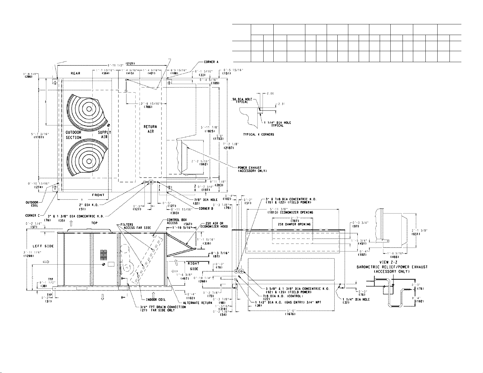
Step 4 — Make Unit Duct Connections — Unit
is shipped for thra-the-bottom duct connections. Ductwork
openings are shown in Fig. 1, 4, and 5. Duct connections are
shown in Fig. 6. Field-fabricated concentric ductwork may be
connected as shown in Fig. 7 and 8. Attach all ductwork to roof
curb and roof cuit) basepans.
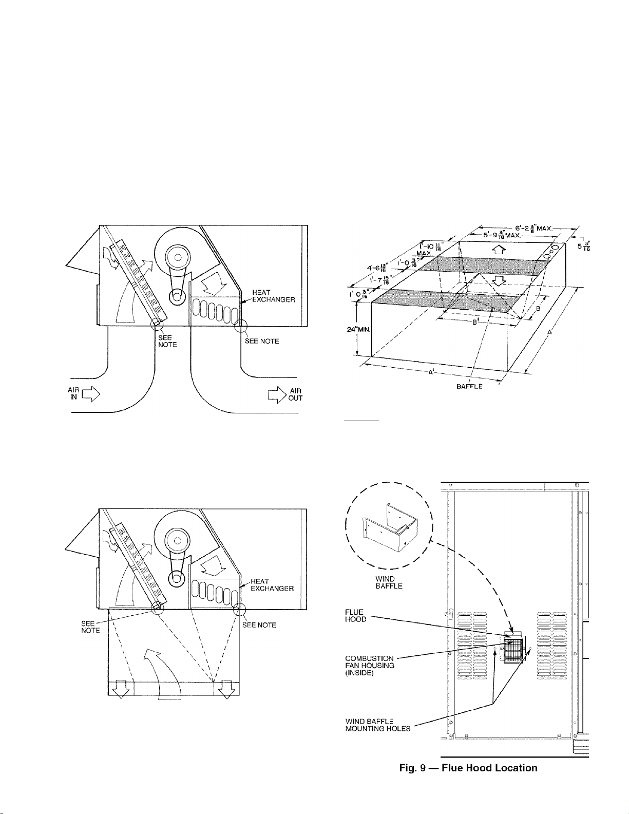
Step 5 — Install Flue Hood and Wind Baffle —
Flue hood and wind baffle are shipped secured under main
control box. To install, secure flue hood to access panel. See
Fig. 9. The wind baffle is then installed over the flue hood.
NOTE: When properly installed, flue hood will line up with
combustion tan housing. See Fig. 10.
Step 6 — Trap Condensate Drain — See Fig. 11
for drain location. One ^4-in. half coupling is provided inside
unit evaporator section for condensate drain connection. An
S'A-in. X ^4-in. diameter and 2-in. x diameter pipe nip
ple, coupled to standard V4-in. diameter elbows, provide a
straight path down through hole in unit base rtiils (see Fig. 12).
A trap at least 4-in. deep must be used.
NOTE: Do not drill in this area; damage to basepan may result in
water leak.
Fig. 6 — Air Distribution — Thru-the-Bottom
NOTE: Dimensions A, A', and B' are obtained trom field-supplied
ceiling diffuser.
I r| Shaded area indicates block-off panels.
Fig. 8 — Concentric Duct Details
AIR OUT AIR IN
NOTE: Do not drill in this area; damage to basepan may result in
water leak.
AIR OUT
Fig. 7 — Concentric Duct Air Distribution
Page 10

INDUCED DRAFT
MOTOR
Step 7 — Orifice Change — This unit is factoiy as
sembled for heating operation using natural gas at an elevation
from sea level to 2000 ft. Tliis unit uses orifice type
LH32RFnnn, where “nnn” indicates the orifice size based on
drill size diameter in thousands of an inch.
HIGH ELEVATION (Above 2000 ft) — Use accessoiy high
altitude kit when installing tliis unit at an elevation of 2000 to
7000 ft. For elevations above 7000 ft, refer to Table 2 to identi
fy the correct orifice size for fhe elevafion. See Table 3 for the
number of orifices required for each unit size. Purchase these
orifices from your local Carrier dealer. Follow instmctions in
accessoiy Installation Instmctions to install the correct orifices.
Table 2 — Altitude Compensation*
COMBUSTION MAIN BURNER HEAT EXCHANGER
FAN HOUSING SECTION SECTION
Pig -|o — Combustion Fan Housing Location
Fig. 11 — Condensate Drain Details
(48TJ016 Shown)
ELEVATION (ft)
0-1,999 30 29
2,000 30 29
3,000 31 30
4,000 31 30
5,000 31 30
6,000 31 30
7,000 32 31
8,000 32 31
9,000 33 31
10,000 35 32
*As the height above sea level Increases, there is less oxygen per
cubic foot of air. Therefore, heat input rate should be reduced at
higher altitudes. Includes a 4% input reduction per each 1000 ft.
fOrifices available through your Carrier dealer.
NATURAL GAS ORIFICEf
Low Heat High Heat
Table 3 — Orifice Quantity
UNIT ORIFICE QUANTITY
48TJD016 5
48TJD020,
48TJD024,
48TJD028,
48TJF016
48TJF020,
48TJF024,
48TJF028
7
CONVERSION TO LP (Liquid Propane) GAS -- Use acces
soiy LP gas conversion kit when converting this unit for use
witli LP fuel usage for elevations up to 7000 ft. For elevations
above 7000 ft, refer to Table 4 to identify the correct orifice
size for tlie elevation. See Table 3 for the number of orifices
required for each unit size. Purchase these orifices from your
loctil Carrier dealer. Follow instmctions in accessoiy Installa
tion Instmctions to install the correct orifices.
Table 4 — LP Gas Conversion*
Fig. 12 — Condensate Drain Piping Details
ELEVATION (ft)
0-1,999 36
2,000 37
3,000 38
4,000 38
5,000 39
6,000 40
7,000 41
8,000 41
9,000 42
10,000 43
*As the height above sea level increases, there is less oxygen per
cubic foot of air. Therefore, heat input rate should be reduced at
higher altitudes. Includes a 4% input reduction per each 1000 ft.
fOrifices available through your Carrier dealer.
10
LP GAS ORIFICEf
Page 11
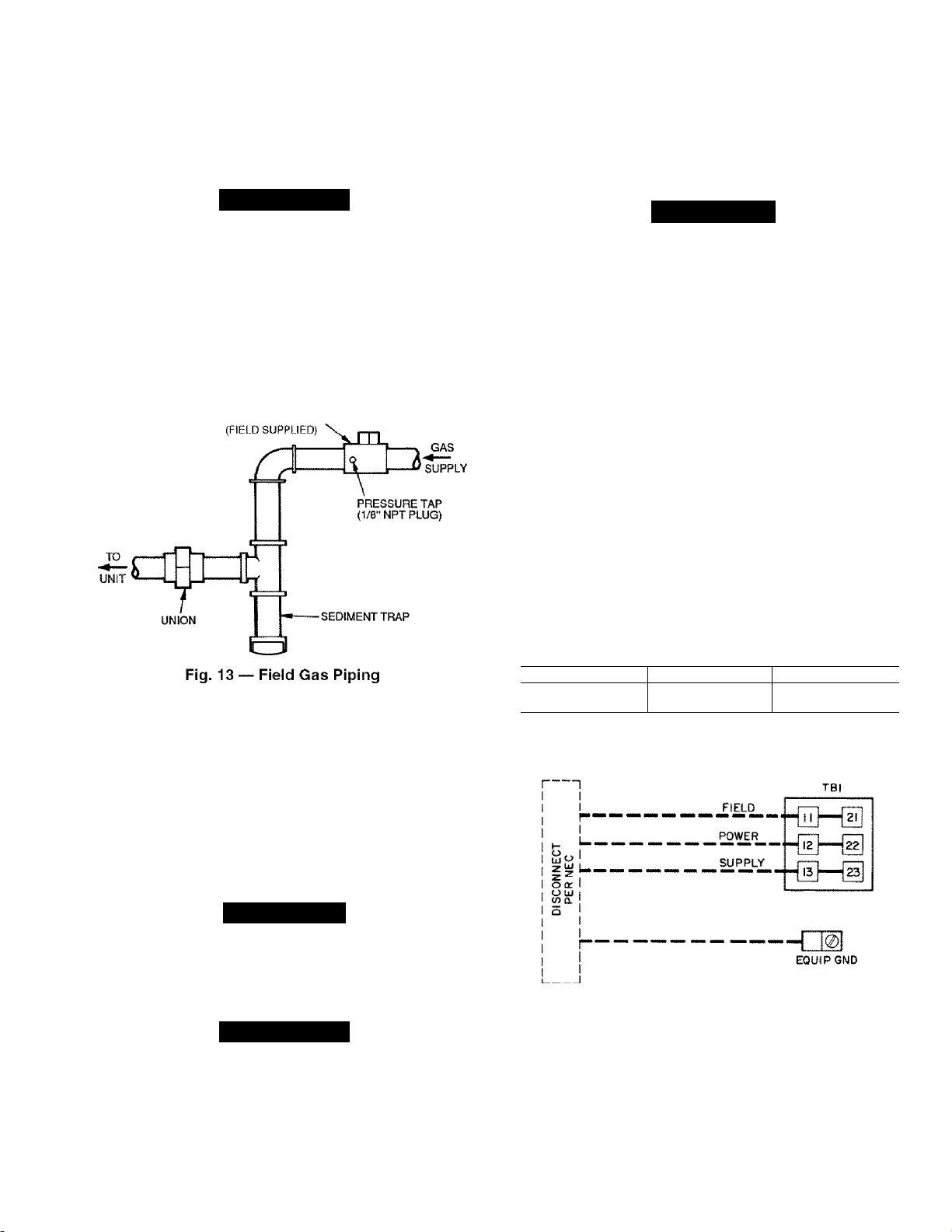
step 8 — Install Gas Piping — Unit is equipped for
use with natui'iil gas. Installation must conform with local
building codes or. in the absence of lociil codes, with the
National Fuel Gas Code. ANSI Z22.3.1.
Install field-supplied manual gas shutoff valve with a Vs-in.
NPT pressure tap for test gage connection at unit. Field gas pip
ing must include sediment trap and union. See Fig. 1.1.
Transformer no. 1 is wired for 230-v unit. If 208/230-v unit
is to be nan with 208-v power supply, the transformer must be
rewired as follows:
1. Remove cap from red (208 v) wire,
2. Remove cap from orange (230 v) spliced wire.
3. Replace orange wire with red wire.
4. Recap both wires.
A WARNING
Do not pressure test gas supply while connected to unit.
Always disconnect union before servicing. Exceeding
maximum manifold pressure may cause explosion and
injuiy.
IMPORTANT: Natural gas pressure at unit gas connec
tion must not be less than 5.5 in. wg or greater than
1.3.5 in. wg.
Size gas-supply piping for 0.5-in. wg maximum pressure
drop. Do not use supply pipe smiillei' than unit gas connection.
MANUAL SHUTOFF
step 9 — Make Electrical Connections
FIELD POWER SUPPLY — Unit is factoiy wired for volt
age shown on nameplate.
When instiilling units, provide a disconnect per NEC (Na
tional Electrical Code) of adequate size (Table 5).
All field wiring must comply with NEC and local
requirements.
Route power ground lines through control box end panel or
unit basepan (see Fig. 4 and 5) to connections as shown on unit
wiring diagram and Fig. 14.
A CAUTION
Be certain unused wires are capped. Failure to do so may
damage the transformers.
Operating voltage to compressor must be within voltage
range indicated on unit nameplate. On 3-phase units, voltages
between phases must be balanced within 2%.
Unit failure as a result of operation on improper line voltage
or excessive phase imbalance constitutes abuse and may cause
damage to electrical components.
FIELD CONTROL WIRING — Install a Carrier-approved
accessoiy thermostat assembly according to installation in-
stmctions included with accessoiy. Locate thermostat assembly
on a solid interior wall in the conditioned space to sense aver
age temperature.
Route thermostat cable or equivalent single leads of
colored wire from subbase terminals through conduit in unit to
low-voltage connections as shown on unit label wiring diagram
and in Fig. 15.
NOTE: For wire nans up to 50 ft, use no. 18 AWG (American
Wire Gage) insulated wire (35 C minimum). For 50 to 75 ft,
use no. 16 AWG insulated wire (.35 C minimum). For over
75 ft, use no. 14 AWG insulated wire (35 C minimum). All
wire larger than no. 18 AWG cannot be directly connected at
tlae thermostat and will require a junction box and splice at the
tliermostat.
Set heat anticipator settings as follows:
VOLTAGE W1 W2
208/230,575 0.98 0.44
460 0,80 0.44
Settings may be changed slightly to provide a greater degree
of comfort for a particulai' installation.
A CAUTION
Tlie correct power phasing is critical in the operation of the
scroll compressor. An incorrect phasing will cause the
compressor to rotate in the wrong direction. This may lead
to premature compressor failure.
A WARNING
Tlie unit must be electrically grounded in accordance with
local codes and NEC ANSl/NFPA 70 (National Fire Pro
tection Association) to protect against fire and electric
shock.
Field wiring must confirm to temperature limitations for
type “T’ wire. All field wiring must comply with NEC and lo
cal requirements.
LEGEND
EQUIP — Equipment
GND — Ground
NEC — National Electrical Code
TB — Terminal Block
NOTE: The maximum wire size for TB1 is 2/0.
Fig. 14 — Field Power Wiring Connections
11
Page 12
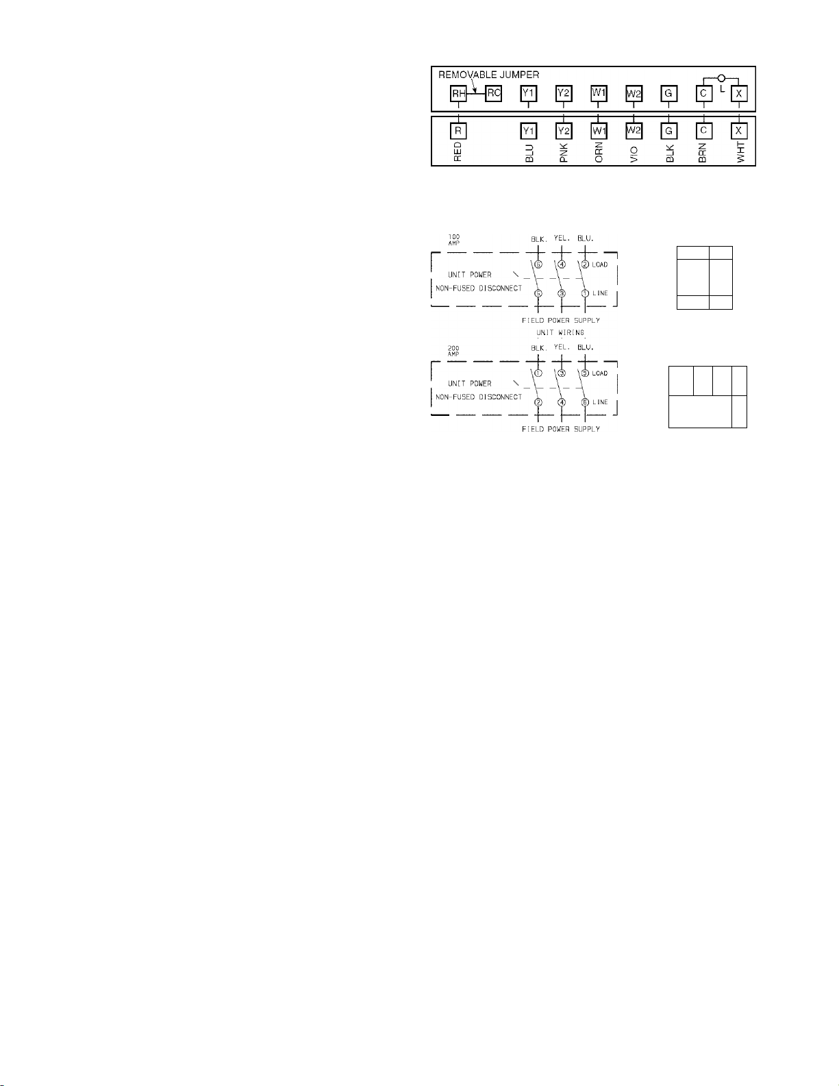
OPTIONAL NON-FUSED DISCONNECT — On units with
the optional non-fused disconnect, incoming power will be
wired into the disconnect switch. Refer to Fig, 16 for wiring
for 100 and 200 amp disconnect switches. Units with an
MOCP under 100 will use the 100 amp disconnect switch.
Units with an MOCP over 100 will use the 200 amp discon
nect switch. Refer to the applicable disconnect wiring diagram.
To prevent breakage during shipping, the disconnect handle
and shaft aie shipped and packaged inside the unit control box.
Install the disconnect handle before unit operation. To install
the handle and shaft, perform the following procedure:
1. Open the control box door and remove the handle and
shaft from shipping location.
2. Loosen the Allen bolt located on the disconnect switch.
Tlie bolt is located on the square hole and is used to hold
the shaft in place. Tlie shaft cannot be inserted until the
Allen bolt is moved.
3. Insert the disconnect shaft into the sqiuu'e hole on the dis
connect switch. The end of the shaft is specially cut and
the shaft can only be inserted in the correct orientation.
4. Tighten the Allen bolt to lock the shaft into position.
5. Close the control box door.
6. Attach the handle to the external access door with the two
screws provided. When the handle is in the ON position,
the handle will be vertical. When the handle is in tlie OFF
position, the handle will be horizontal.
7. Turn tlie handle to the OFF position and close the door.
Tlie handle should fit over the end of the shaft when the
door is closed.
8. The handle must be in the OFF position to open the con
trol box door.
OPTIONAL CONVENIENCE OUTLET--On units with
optiontil convenience outlet, a 115-v GFI (ground fault interrttpt) convenience outlet receptacle is provided tor field wiring.
Field wiring should be nm through the Vs-in. knockout pro
vided in the basepan near the return air opening.
THERMOSTAT ASSEMBLY
Fig. 15 — Field Control Thermostat Wiring
6T3 4T2 2Tl LOAD
#11®
■ “È
PI P
Pi
5L3 3L2 1L1 LINE
□ □ □
'^N N N
OHO
2 4 E
NOTE: The disconnect takes the place of TB-1 as shown on the unit wiring
diagram label and the component arrangement label.
Fig. 16 — Optional Non-Fused Disconnect Wiring
12
Page 13

Table 5 — Electrical Data
UNIT
48TJ
016
(15 Tons)
020
(18 Tons)
024
(20 Tons)
028
(25 Tons)
FLA — Full Load Amps
HACR — Heating, Air Conditioning and Refrigeration
!FH/l ~ Indoor (Evaporator) Fan Motor
LRA — Locked Rotor Amps
MCA — Minimum Circuit Amps
MOCP — Maximum Overcurrent Protection
NEC — National Electrical Code
OFM — Outdoor (Condenser) Fan Motor
RLA — Rated Load Amps
'Fuse or HACR circuit breaker.
NOTES:
1. In compliance with NEC requirements for multimofor and combinafion load
equipmenf (refer fo NEC Articles 430 and 440), the overcurrent protective
device for the unit shall be fuse or HACR breaker, Canadian units may be
fuse or circuit breaker,
2. Unbalanced 3-Phase Supply Voltage
Never operate a motor where a phase imbalance in supply voltage Is
greater than 2%. Use the following formula to determine the percent of volt
age imbalance.
% Voltage Imbalance
too X
NOMINAL
VOLTAGE
(3 Ph, 60 Hz)
208/230 187 253 25.6 190 25.6 190 3 0.5 1.7 3.7 10.5/11.0
460 414 508 13.5 95 13.5 95 3 0.5 0.8 3.7 4.8
575 5f8 632 10.2 75 10.2 75 3 0.5 0.8 3.0 3.9
208/230 187 253 33 237 23 184 3 0.5 1.7 5.0 15,8/15.8
460 414 508 16.2 130 10.2 90 3 0.5 0.8 5.0 7.9
575 518 632 12.7 85 9 73 3 0.5 0.8 5.0 6,0
208/230 187 253 33 237 29.5 237 2 1 6.6 7.5 25.0/25.0
460 414 508 16.2 130 14.1 130 2 1 3.3 7.5 13.0
575 518 632 12.7 85 11.3 85 2 1 3.4 7.5 10.0
208/230 187 253 47.5 265 33 237 2 1 6.6 10.0 28.0/28.0
460 414 508 22.9 145 16.2 130 2 1 3.3 10.0 14.6
575 518 632 17.9 102 12.7 85 2 1 3.4 10.0 13.0
LEGEND
max voltage deviation from average voltage
VOLTAGE
RANGE
Min Max RLA LRA RLA LRA Qty
average voltage
COMPRESSOR
No. 1 No. 2
OFM IFM
FLA (ea)
Hp
Hp
Example: Supply voltage is 460-3-60.
ABC
Determine maximum deviation from average voltage.
(AB) 457 - 452 = 5 V
(BC) 464 - 457 = 7 v
(AC) 457-455 = 2 V
Maximum deviation is 7 v.
Determine percent of voltage imbalance.
% Voltage Imbalance = f 00 x
This amount of phase imbalance is satisfactory as it is below the maximum
allowable 2%.
IMPORTANT: If the supply voltage phase imbalance is more than
2%, contact your local electric utility company immediately.
POWER
EXHAUST
COMBUSTION
FAN MOTOR
POWER
SUPPLY
FLA FLA LRA FLA MCA MOCP*
4,6 18.8 0.57 79/79 100/100
2.3 6.0 0.30 40 50
— — 0.57 30 35
2.1 4.8 0.57 32 40
— — 0.57 85/85 110/110
4.6 18.8 0.57 90/90 110/110
— — 0.30 41 50
2,3 6.0 0,30 43 50
— —
2,1 4.8 0.57 35 45
0.57 74/74 90/90
0.30 38 50
0.57 33 45
— — 0.57 109/109 125/125
4,6 18.8 0.57 114/114 125/125
— —
2,3 6.0 0.30 56 70
2.1 4.8 0.57 46 50
—
4.6 18.8 0.57 138/138 175/175
— —
2.3 6.0 0.30 68 90
— — 0.57 55 70
2,1 4.8 0.57 57 70
AB = 452 V
BC = 464 V
AC = 455 V
Average Voltage ;
= t .53%
0.30 54 70
0.57
0.57 134/134 175/175
0.30 66 80
452 + 464 + 455
f37f
= 457
7
457
44
50
13
Page 14

step 10 — Make Outdoor-Air Inlet Adjust
ments
MANUAL OUTDOOR-AIR DAMPER ^ All units (except
those equipped with a factoiy-instiilled economizer) have a
manual outdoor-air damper to provide ventilation air.
Damper can be preset to admit up to 25% outdoor air into
return-£iir compartment. To adjust, loosen securing screws and
move damper to desired setting, tlien retighten screws to secure
diunper (see Fig. 17).
25% ADJUSTABLE
AIR DAMPER
SECURING SCREWS
Fig. 17
Standard 25% Outdoor-Air
Section Details
Step 11 — Install Outdoor-Air Hood
Fig. 18 — Outdoor-Air Hood Component Location
HOOD DRAIN
PAN
IMPORTANT: If the unit is equipped with the optional
EconoMi$eiTV, move the outdoor air temperature sensor
prior to installing the outdoor air hood. See the Optional
EconoMi$eiTV and EconoMi$er2 section for more details.
Tlie outdoor- air hood is common to 25% air ventilation and
economizer. If EconoMi$erIV is used, all electrical connec
tions have been made and adjusted at the factory. Assemble
and install hood in the field.
NOTE: Tlie hood top panel, upper and lower filter rettdners,
hood drain pan, baffle (size 024 and 028), and filter support
bracket iu'e secured opposite the condenser end of the unit. The
screens, hood side panels, remaining section of filter support
bracket, seal strip, and hai'dware are in a package located
inside the return-air filter access panel (Fig. 18).
1. Attach seal strip to upper filter retainer. See Fig. 19.
2. Assemble hood top panel, side panels, upper filter retain
er, and drain pan (see Fig. 20).
.2. Secure lower filter retainer and support bracket to unit.
See Fig. 20. Leave screws loose on size 024 and 028
units.
4. Slide baffle (size 024 and 028) behind lower filter retainer
and tighten screws.
5. Loosen sheet metal screws for top panel of base unit
located above outdoor-air inlet opening, and remove
screws for hood side panels located on the sides of the
outdoor-air inlet opening.
6. Match notches in hood top panel to unit top panel screws.
Insert hood flange between top panel flange and unit.
Tighten screws.
7. Hold hood side panel flanges flat against unit, and instiill
screws removed in Step 5.
8. Inseit outdooi'-air inlet screens and spacer in channel cre
ated by lower filter retainer and filter support bracket.
BAFFLE
14
Page 15

step 12 — Install All Accessories— install all
field-installed accessories. Refer to the accessoiy installation
instructions included with each accessoiy.
MOTORMASTER® I CONTROL INSTALLATION
(48TJ0I6,020 UNITS)
Install Field-Fabricated Wind Baffles — Wind baffles must
be field-fabricated for all units to ensure proper cooling cycle
operation at low ambient temperatures. See Fig. 21 for baffle
detiiils. Use 20-gage, galvanized sheet metal, or similar
coiTosion-resistant metal for baffles. Use field-supplied screws
to attach baffles to unit. Screws should be V4-in. diameter and
5/8-in. long. Drill required screw holes for mounting baffles.
A CAUTION
To avoid diunage to the refrigerant coils and electrical com
ponents, use recommended screw sizes only. Use care
when drilling holes.
NOTE: Dimensions in ( ) are in mm.
Fig. 21 — Wind Baffle Details
Install Motormaster I Controls — Only one Motormaster I
control is required per unit. Tlie Motormaster I control must be
used in conjunction with the Accessoiy 0° F Low Ambient Kit
(purchased separately). Tlie Motonnaster I device controls out
door fan no. I while outdoor fans no. 2 and ."5 are sequenced off
by the Accessoiy 0° F Low Ambient Kit.
Accessory 0° F Low Ambient Kit — Instiill the Accessoiy 0° F
Low Ambient Kit per instmction supplied with accessoiy.
Sensor Assembly — Install the sensor assembly in the location
shown in Fig. 22.
Motor Mount — To ensure proper fan height, replace the exist
ing motor mount with the new motor mount provided with
accessoiy.
Transformer (460 and 575-v Units Only) — On 460 and 575-v
units, a transfonner is required. The transformer is provided
with the accessoiy and must be field-installed.
Motormaster I Control — Recommended mounting location is
on the inside of the panel to the left of the control box. The
control should be mounted on the inside of the panel, verti
cally, with leads protniding from bottom of extinsion.
0
îî°o
0 0
cp o
0 0
cp o
îi°°
cp 0
(b 0
cp 0
0 0
G) o
d) o
G) o cp o
® 0
d> 0
<p 0
îî ° 0
d> 0
(p 0
Î0 0
(p 0
cp 0 t p 0
cp o
SENSOR LOCATION
cp o
© 0
è 0
G) 0
0 0
G) o
© o
cb 0
îi°°
0 0
îi“°
G) o
îi°°
cp 0
îî°o
<p 0
G) 0
SENSOR
LOCATION
HAiRPIN END
NOTE: All sensors are located on the eighth hairpin up from the
bottom.
48TJ016
----------
HAIRPIN END
ïh-
cp o
ih"
il»
cp 0
il»
cp 0
il»
cp o
il"
il»
tp 0
il»
cp 0
il»
cp 0
il»
cp 0
il»
il»
il»
cp 0
il»
cp 0
il»
cp o
il»
cp o
il»
tp 0
il»
cp 0
il»
48TJ020
Fig. 22 — Motormaster I Sensor Locations
15
Page 16

MOTORMASTER® V CONTROL INSTALLATION
(48TJ024,028 UNITS)
Install Lield-Fabricated Wind Baffles — Wind baffles must
be field-fabricated for all units to ensure proper cooling cycle
operation at low ambient temperatures. See Fig. 21 for baffle
details. Use 20-gage, galvanized sheet metal, or similar coito-
sion-resistant metal for baffles. Use field-supplied screws to at
tach baffles to unit. Screws should be ‘A-in. diameter and
5/s-in. long. Drill required screw holes for mounting baffles.
A 0j|^||Y|Q||
To avoid dmnage to the refrigerant coils and electrical com
ponents, use recommended screw sizes only. Use cru'e
when diilling holes.
Install Motormaster V Controls — Tlie Motormaster V
(MMV) control is a motor speed control device which adjusts
condenser fan motor speed in response to declining liquid re
frigerant pressure. A properly applied Motormaster V control
extends the operating range of air-conditioning systems and
permits operation at lower outdoor ambient temperatures.
Tlie minimum iunbient temperatures at which the unit will
operate are:
TEMPERATURE OPERATING LIMÌTS — F°
standard Unit with Unit with
Unit Low Ambient Kit MMV Control
40 25 -20
To operate down to the ambient temperatures listed,
Motomiaster V controls (Fig. 23) must be added. Field-fabricat
ed and installed wind baffles iu'e also required for iill units (see
Fig. 21). The Motormaster V control permits operation of the
unit to an ambient temperature of-20 F. Tlie control regulates the
speed of 3-phase fan motors that aie compatible with the control.
Tliese motors are factoiy installed.
See Table 6 for the Motormaster V control accessoiy pack
age usage. Table 7 shows applicable voltages and motors.
Replacement of motor or fan blade IS NOT REQUIRED ON
CURRENT PRODUCTION UNITS since the control is
compatible with the factoiy-installed fan motors. Only field
wiring control is required
Install the Motormaster V control per instiuctions supplied
with accessoiy.
FR<3M FUSE BLOCK
Ó O Ò O Ó
U
TO PRESSURE^
TRANSDUCER
U L3
12 13Ai
I n io/-\
256
IflrtDfVÌÓnrTnhDnrvnfìDITri
/;n 7Î Î3 B-
O Q O O O
G
5
o
C E [3
TO MOTOR(S)
Fig. 23
Table 6 — Motormaster V Control Package Usage
UNIT VOLTAGE ITEM DESCRIPTION
48TJ024,028 460 CRLOWAÌVIB016A00
Table 7 — Applicable Voltages and Motors
VOLTAGE COMPATIBLE MOTOR
208/230-3-60 HD52AK654
460-3-60 HD52AK654
575-3-60 HD52GE576
Motormaster V Control
208/230 CRLOWAIVIB015A00
575 CRLOWAW1B017A00
16
Page 17

step 13 — Adjust Factory-Installed Options
PREMIERLINKTM CONTROL — The PremierLink control
ler is available as a special order from the factoiy and is com
patible with the CiU'rier Comfort Network® (CCN) system.
This control is designed to allow usere the access and ability to
change factoiy-defmed settings, thus expanding the function of
the standard unit control board. Carrier’s diagnostic standard
tier display tools such as Navigator''^' device or Scrolling
Marquee can be used witli the PremierLink controller.
Tire PremierLink controller (see Fig. 24) requires the use of
a Cai'rier electronic themnostat or a CCN connection for time
broadcast to initiate its internal timeclock. This is necessaiy for
broadcast of time of day functions (occupied/unoccupied). No
sensors are supplied with the field-mounted PremierLink con
trol. The factoiy-installed PremierLink conti'ol includes only
the supply-air temperature (SAT) sensor and the outdoor air
temperature (OAT) sensor as standiu'd. An indoor air quality
(CO2) sensor can be added as an option. Refer to Table 8 for
sensor usage. Refer to Fig. 25 for PremierLink controller wir
ing. The PremierLink control may be mounted in the control
panel or an area below the control panel.
NOTE: PremierLink controller version 1.3 and later is shipped
in Sensor mode. If used with a thermostat, the PremierLink
controller must be configured to Thermostat mode.
Install the Supply Air Temperature (SAT) Sensor — When
the unit is supplied with a factoiy-mounted PremierLink con
trol, the supply-air temperature (SAT) sensor (33ZCSENSAT)
is factoiy-supplied and wired. The wiring is routed from the
PremierLink control over the control box, through a grommet.
into the fan section, down along the back side of the fan, and
along the fan deck over to the supply-air opening.
The SAT probe is wire-tied to tire supply-air opening (on the
horizontal opening end) in its shipping position. Remove the
sensor for installation. Re-position the sensor in the flange of
tire supply-air opening or in the supply air duct (as required by
local codes). Drill or punch a ‘/2-in. hole in the flange or duct.
Use two field-supplied, self-drilling screws to secure the sensor
probe in a horizontal orientation.
NOTE: The sensor must be mounted in tire dischiu'ge airstream
downstream of the cooling coil and any heating devices. Be
sure the probe tip does not come in contact with any of the unit
or heat surfaces.
Outdoor Air Temperature (OAT) Sensor — When the unit is
supplied with a factoiy-mounted PremierLink control, the
outdoor-air temperature sensor (OAT) is factoiy-supplied and
wired.
Install the Indoor Air Quality (CQt) Sensor — Mount the
optional indoor air quality (CO2) sensor according to manufac
turer specificiitions.
A sepiii'ate field-supplied transformer must be used to
power the CO2 sensor.
Wire the CO2 sensor to tlie COM and lAQI terminals of J5
on the PremierLink controller. Refer to the PremierLink Instal
lation, Start-up, and Configuration Instnictions for detailed
wiring and configuration information.
HVAC SENSOR INPUTS
SPACE TEMP
SET POINT ^
SUPPLY AIR TEMP
OUTDOOR TEMP
INDOOR AIR QUALITY
OUTDOOR AIR QUALITY
DUAL MODE SENSOR (STAT)
REMOTE OCCUPANCY (Q)
COMP SAFETY (Y1) ^
FIRE SHUTDOWN (Y2) ^
SUPPLY FAN STATUS (W1)
NOT USED (W2) ^
ENTHALPY STATUS (ENTH)
CCN/LEN
PORT
/
NAVIGATOR
PORT
4-2OMA INDOOR COMPR HEAT EXHAUST
ECONOMIZER FAN MOTOR 1&2 LOW/HIGH RVS VALVE
-------------------------------
Fig. 24 — PremierLink Controller
X f M N N
OUTPUTS--------------------------------------------•-
17
Page 18

*lt PremierLink control is in thermostat mode,
tTB2 terminal designations for 24 vac discrete inputs. Default is for DDC control.
Fig. 25 — PremierLink™ Controls Wiring
OAT
PL
SAT
SPT
TB
Outdoor Air Temperature Sensor
Plug
Supply Air Temperature Sensor
Space Temperature Sensor
Terminal Block
Page 19

Table 8 — PremlerLinkT“ Sensor Usage
APPLICATION
Differential Dry Bulb
Temperature with
PremierLink*
(PremierLink
requires 4-20 mA
Actuator)
Single Enthalpy with
PremierLink*
(PremierLink
requires 4-20 mA
Actuator)
Differential Enthalpy
with PremierLink*
(PremierLink
requires 4-20 mA
Actuator)
“PremierLink control requires supply air temperature sensor 33ZCSENSAT and
outdoor air temperature sensor HH79NZ039 — included with factory-installed PremierLink control;
field-supplied and field-installed with field-installed PremierLink control.
NOTES:
1. CO2 Sensors (Optional):
33ZCSENC02 — Room sensor (adjustable). Aspirator box is required for duct mounting of the sensor.
33ZCASPC02 — Aspirator box used for duct-mounted CO2 room sensor.
33ZCT55C02 — Space temperature and C02 room sensor with override.
33ZCT56C02 — Space temperature and CO2 room sensor with override and setpoint.
2. All units include the following Standard Sensors:
Outdoor-air sensor — 50HJ540569 — Opens at 67 F, closes at 52 F, not adjustable.
Mixed-air sensor — HH97AZ001 — (PremierLink control requires supply air temperature sensor 33ZCSENSAT
and outdoor air temperature sensor HH79NZ039)
Compressor lockout sensor — 50FIJ540570 — Opens at 35 F, closes at 50 F.
OUTDOOR AIR
TEMPERATURE SENSOR
Included —
HH79NZ039
Included —
Not Used
Included —
Not Used
ENTHALPY SWITCH/RECEI VER -- Tlie accessoiy en
thalpy switcli/receiver (33CSENTHSW) senses temperature
and humidity of the ttir surrounding the device and calculates
the enthalpy when used witliout ttn entlitilpy sensor. The relay is
energized when enthalpy is high and deenergized when en
thalpy is low (based on ASHRAE [American Society of Heat
ing, Refrigeration and Air Conditioning Engineers] 90.1 crite
ria), If tin accessoiy enthtilpy sensor (33CSENTSEN) is at
tached to the return air sensor input, then differential enthalpy is
calculated. Tlie relay is energized when the enthalpy detected by
the return air enthalpy sensor is less than the entlialpy at tlie en
thalpy switch/receiver. The relay is deenergized when the en
thalpy detected by the return air enthalpy sensor is greater than
the enthalpy at the enthalpy switch/receiver (differential en
thalpy control). See Fig. 26 and 27.
OUTDOOR ENTHALPY CONTROL (Fig. 28) — Outdoor
enthalpy control requires only an enthalpy switcli/receiver
(33CSENTHSW). The enthalpy switcli/receiver is mounted in
the outdoor air inlet and calculates outdoor air enthalpy. The
enthalpy switch/receiver energizes the relay output when the
outdoor enthalpy is above 28 BTU/lb OR city bulb tempera
ture is above 75 F and is deenergized when the outdoor
enthalpy is below 27 BTU/lb
AND diy bulb temperature is
below 74.5 F. The relay output is wired to the unit economizer
which will open or close depending on the output of the
switch.
NOTE: The enthalpy calculation is done using an average alti
tude of 1000 ft above sea level.
RETURN AIR
TEMPERATURE SENSOR
Required —
33ZCT55SPT
or Equivalent
—
—
intake). Tlie enthalpy switch/receiver is not a NEMA 4
(National Electrical Manufacturers Association) enclosure and
should be mounted in a location that is not exposed to outdoor
elements such as rain or snow. Use two field-supplied no. 8 x
^/4-in. ТЕК screws. Insert the screws tlirough the holes in the
sides of the enthalpy switch/receiver.
Wiring — Сш'пег recommends the use of 18 to 22 AWG
(American Wire Gage) twisted pair or shielded cable for all
wiring. All connections must be made with Vq-in. female spade
connectors.
A 24-vac transformer is required to power the enthalpy
switch/receiver; as shown in Fig. 29, the PreniierLinkTM board
provides 24 vac. Connect the GND and 24 VAC terminals on
tlie enthalpy switcli/receiver to the terminals on the transfonner. On some applications, the power from the economizer har
ness can be used to power the enthalpy switcli/receiver. To
power tlie enthalpy switcli/receiver from the economizer har
ness, connect power of tlie enthalpy switcli/receiver to the red
and brown wires (1 and 4) on the economizer hiuness.
For connection to rooftop units with PremierLink'’'* control,
connect the LOW Enthalpy terminal on the enthalpy switch/re
ceiver to J4 — pin 2 of tlie PremierLink control on the HVAC
unit. The switch can be powered through tlie PremierLink con
trol board if desired. Wire the 24 VAC teniiinal on the entlialpy
switch/receiver to J4 — pin 1 on the PremierLink control. Wire
tlie GND terminal on the enthalpy switch/receiver to Jt —
pin 2 on the PremierLink control. The HI Enthalpy terminal is
not used. See Fig. 28.
Mounting — Mount the enthalpy switch/receiver in a location
where tlie outdoor air can be sampled (such as the outdoor air
OUTDOOR AIR
ENTHALPY SENSOR
— —
Required —
33CSENTHSW
(HH57ZC003)
or
HH57AC077
Required —
33CSENTHSW
(HH57ZC003)
or
HH57AC077
RETURN AIR
ENTHALPY SENSOR
—
Required —
33CSENTSEN
or
HH57AC078
19
Page 20

4.253"
(108.03mmJ
4,253"
(1Q8.03mrn)
©
.251
(6.35mn>)
33CSENTHSW
mm
Hi LCW GNO
Eioafv
o
3 ™
3 "
Thermistor - Humidity Sensor
Fig. 26 — Enthalpy Switch/Receiver Dimensions
Mcdel«: HHSTZCO03
Pcwar: 24 VAC
Oajp«t: 10 AFona. IC
24 VAC Sourced Power
(95.25mm)
(33CSENTHSW)
33CSENTSEN
.25'
(8,36 mm)
3
3 ■
^ o:'
3 Oí
Thermistor
Modelé; HH5?ZC00l
Powe-: 24 to 36 VDC
0 to 50 BTÜ/S»
OuQkiI: 4 to 20 raA
3.75"
(95,25mm)
• Humidity Sensor
a
•fc- bi
o
3 ^
3 ■
Fig. 27 — Enthalpy Sensor Dimensions
(33CSENTSEN)
J3RV », JDRII
"e'RY^'^ red”
20
Page 21

DIFFERENTIAL ENTHALPY CONTROL (Fig. 29) —
Differentiiil enthalpy control requires both an enthiilpy switch/
receiver (.33CSENTHSW) and an enthtJpy sensor
(33CSENTSEN), The enthalpy switch/receiver is mounted in
the outdoor air inlet and calculates outdoor air enthalpy. The
enthalpy sensor is mounted in the return airstream and ciilculates the enth;ilpy of the indoor air.
Tire enthalpy switclr/receiver energizes the HI Enthalpy re
lay output when the outdoor enthalpy is greater tlran tire indoor
enthalpy. Tire LOW Entlralpy terminal is energized when the
outdoor entlralpy is lower than the indoor enthalpy. Tire relay
output is wired to the unit economizer which will open or close
depending on the output of the switch.
NOTE; Tire enthalpy calculation is done using an average alti
tude of 1000 ft above sea level.
Mounting — Mount the enthalpy switch/receiver in a location
where tire outdoor air can be sampled (such as the outdoor air
intitke). Tire enthalpy switch/receiver is not a NEMA 4 enclo
sure and should be mounted in a location that is not exposed to
outdoor elements such as rain, snow, or direct sunlight. Use
two field-supplied no. 8 x Yr-in. ТЕК screws. Insert the screws
through the holes in the sides of the enthalpy switclr/receiver.
Mount the enthalpy sensor in a location where the indoor air
can be siunpled (such as the return air duct). Tire enthalpy
sensor is not a NEMA 4 enclosure and should be mounted in a
location that is not exposed to outdoor elements such as rain or
snow. Use two field-supplied no. 8 x V4-in. ТЕК screws. Insert
the screws tlrrough the holes in tire sides of the enthalpy sensor.
Wiring — Carrier recommends the use of 18 to 22 AWG
twisted pair or shielded cable for all wiring. All connections
must be made with Vr-in. female spade connectors.
The PremierLink'f’'* board provides 24-vac to power the
enthalpy switch/receiver. Connect the GND and 24 VAC termi
nals on the enthalpy switclr/receiver to the terminals on
tire transformer. On some applications, tire power from the
economizer htu'ness can be used to power the enthalpy switch/
receiver. To power the enthalpy switch/receiver from the
economizer harness, connect power of the enthalpy switch/
receiver to the red and brown wires (1 and 4) on the econo
mizer harness.
Connect the LOW Enthalpy terminal on the enthalpy
switch/receiver to J4 — pin 2 of the PremierLink control on the
HVAC unit. The switch can be powered through the Premier
Link control board if desired. Wire tlie 24VAC terminal on the
enthidpy switcli/receiver to J4 — pin 1 on the PremierLink
control. Wire the GND terminal on the enthalpy switch/
receiver to J1 — pin 2 on the PremierLink control. The HI
Enthalpy terminal is not used. See Fig. 28.
Connect the 4-20 mA IN terminal on the enthalpy switch/
receiver to the 4-20 mA OUT terminal on the return air entlialpy sensor. Connect the 24-36 VDC OUT terminiil on the
enthalpy switcli/receiver to the 24-36 VDC IN terminal on the
return air enthalpy sensor. See Fig. 29.
Enthalpy Switch/Receiver Jumper Settings — There are two
jumpers. One jumper determines the mode of the entlialpy
switch/receiver. The other jumper is not used. To access the
jumpers, remove the 4 screws holding the cover on the
enthalpy switcli/receiver and then remove the cover. Tlie factoiy settings for the jumpers £U'e M1 and OFF.
The mode jumper should be set to M2 for differential entlialpy control. The factoiy test jumper should remain on OFF
or the enthalpy switch/receiver will not calculate enthalpy.
LEGEND
N/C — Normally Closed
N/O — Normally Open
120 VAC
LINE VOLTAGE
JUMPER SETTINGS FOR 33CSENTHSW
1°
о 11 о
I
ooo
ooo
JUMPER SETTINGS FOR 33CSENTSEN
0 О cn
^ о О о
1 -S? r-P
■ oo ■ ooo
Boo 1 ooo
Fig. 29 — Differential Enthalpy Control Wiring
21
Page 22

Enthalpy Sensor Jumper Settings — There iii'e two jumpers.
One jumper determines the mode of the enthalpy sensor. The
otlier jumper is not used. To access the jumpers, remove the
4 screws holding the cover on the enthalpy sensor and then re
move the cover. The factory settings for the iumpers are M.3
and OFF.
Tlie mode jumper should be set to M.3 for 4 to 20 mA
output. Tlie factoiy test jumper should remain on OFF or the
enthalpy sensor will not calculate enthiilpy.
ENTHALPY SENSORS AND CONTROL The enthalpy
control (HH57AC077) is supplied as a field-installed accessoiy
to be used with the EconoMi$er2 damper control option. The
outdoor air enthalpy sensor is part of the enthalpy control. The
separate field-installed accessoiy return air enthalpy sensor
(HH57AC078) is required for differential enthalpy control.
NOTE: Tlie entlialpy control must be set to tire “D” setting for
differential entlialpy control to work properly.
Tlie enthalpy control receives tlie indoor and return
enthalpy from the outdoor and return air enthalpy sensoii; and
provides a diy contact switch input to the PremierLink'M
controller. Locate the controller in place of an existing econo
mizer controller or near the actuator. The mounting plate may
not be needed if existing bracket is used.
A closed contact indicates that outside air is preferred to the
return air. An open contact indicates that the economizer
should remain at minimum position.
Outdoor Air Enthalpy Sensor/Enthalpv Controller
(HH57AC077) — To wire the outdoor air enthalpy sensor,
perform the following (see Eig. .30 and .31):
NOTE: The outdoor air sensor can be removed from the back
of the enthiilpy controller and mounted remotely.
1, Lise a 4-conductor, 18 or 20 AWG cable to connect the
enthalpy control to the PremierLink controller and power
transformer.
2. Connect the following 4 wires from the wire hiu'ness
located in rooftop unit to the enthalpy controller:
a. Connect the BRN wire to the 24 vac terminal (TRl)
on enthalpy control and to pin 1 on 12-pin harness.
b. Connect the RED wire to the 24 vac GND terminal
(TR) on enthalpy sensor and to pin 4 on 12-pin
harness.
c. Connect the GRAY/ORN wire to J4-2 on Premier
Link controller and to terminal (.3) on enthalpy
sensor.
d. Connect the GRAY/RED wire to J4-1 on Premier
Link controller and to terminal (2) on enthalpy sensor.
NOTE: If installing in a Canier rooftop, use the two gray wires
provided from the control section to the economizer to connect
PremierLink controller to terminals 2 and 3 on enthiilpy sensor.
Return Air Enthalpy Sensor — Mount the return-air enthalpy
sensor (HH57AC078) in the return-air duct. Tlie return air
sensor is wired to the enthalpy controller (HH57AC077). The
outdoor enthiilpy changeover set point is set at the controller.
To wire the return air enthalpy sensor, perform the follow
ing (see Fig. 30):
1, Use a 2-conductor, 18 or 20 AWG, twisted pair cable to
connect the return air enthalpy sensor to the enthalpy
controller.
At the enthalpy control remove the factoiy-installed
resistor from the (SR) and (-I-) terminals.
Connect the field-supplied RED wire to (-I-) spade
connector on the return air enthalpy sensor and the (SR-i-)
terminal on the enthalpy controller. Connect the BLK
wire to (S) spade connector on the return air enthalpy
sensor and the (SR) terminal on the enthalpy controller.
NOTES:
1. Remove factory-installed jumper across SR and + before con
necting wires from return air sensor.
2. Switches shown in high outdoor air enthalpy state. Terminals 2
and 3 close on low outdoor air enthalpy relative to indoor air
enthalpy.
3. Remove sensor mounted on back of control and locate in out
side airstream.
Fig. 30 — Outdoor and Return Air Sensor Wiring
Connections for Differential Enthalpy Control
-BRACKET
HH57AC077
ENTHALPY
CONTROL AND
OUTDOOR AIR
ENTHALPY SENSOR
HH57AC078 ENTHALPY
SENSOR (USED WITH
ENTHALPY CONTROL
FOR DIFFERENTIAL
ENTHALPY OPERATION)
MOUNTING PLATE
Fig. 31 — Differential Enthalpy Control,
Sensor and Mounting Plate (33AMKITENT006)
22
Page 23

OPTIONAL ECONOMISER!V AND ECONOMISER2 —
See Fig. 32 and 33 for EconoMiSerlV component locations.
See Fig. 34 for EconoMi$er2 component locations.
NOTE: These instinctions are for installing the optional
EconoMiSerlV and EconoMi$er2 only. Refer to the accessory
EconoMiSerlV or EconoMi$er2 installation instaictions when
field installing an EconoMiSerlV orEconoMi$er2 accessory.
To complete instiillation of the optional EconoMiSerlV, per
form the following procedure.
1. Remove the EconoMiSerlV hood. Refer to Step 11 — In
stall Outdoor-Air Hood on page 14 for infonnation on
removing and installing the outdoor-iiir hood.
2. Relocate outdoor air temperature sensor from shipping
position to operation position on EconoMiSerlV. See
Fig. 32.
IMPORTANT: F;iilure to relocate the sensor will result in
the EconoMiSerlV not operating properly.
OUTDOOR AIR
TEMPERATURE SENSOR
3. Reinstall economizer hood.
4. Install till EconoMiSerlV accessories. EconoMiSerlV
wiring is shown in Fig. 35. EconoMiSer2 wiring is shown
in Fig. 36.
Outdoor air leakage is shown in Table 9. Return £iir pressure
di'op is shown in Table 10.
Table 9 — Outdoor Air Damper Leakage
DAMPER STATIC PRESSURE (in. wg)
0.2 0.4 0.6 0.8 1.0 1.2
LEAKAGE (cfm)
35 53 65 75 90 102
Table 10 — Return Air Pressure Drop (In. wg)
CFM
4500 5000 5400 6000 7200 7500 9000 10,000 11,250
0.040 0.050 0.060 0.070 0.090 0.100 0.110 0.120 0.140
SCREWS
Fig. 32 — EconoMiSerlV Component Locations ■
End View
SUPPLY AIR
TEMPERATURE SENSOR
Fig. 33 EconoMiSerlV Component Locations ■
Side View
Fig. 34 — EconoMISer2 Component Locations
23
Page 24

LEGEND
DCV — Demand Controlled Ventilation
lAQ — Indoor Air Quality
LALS— Low Temperature Compressor
Lockout Switch
OAT — Outdoor-Air Temperature
POT — Potentiometer
Potentiometer Detault Settings:
Power Exhaust Middle
Minimum Pos,
DCV Max.
DCV Set
Enthalpy
Fully Closed
Middle
Middle
C Setting
Fig. 35 — EconoMI$erlV Wiring
NOTES:
1. 620 ohm, 1 watt 5% resistor should be removed only when using differential
enthalpy or dry bulb.
2. If a separate field-supplied 24 v transformer is used for the lAQ sensor power
supply, it cannot have the secondary of the transformer grounded.
3. For field-installed remote minimum position POT, remove black wire jumper
between P and PI and set control minimum position POT to the minimum
position.
OAT — Outdoor Air Temperature Sensor
NOTES:
1. Switch on actuator must be in run position for economizer to operate.
2. 50HJ540573 actuator consists of the 50HJ540567 actuator and a harness with 500-ohm resistor.
Fig. 36 — EconoMiSer2 Wiring
24
Page 25

ECONOMISERIV STANDARD SENSORS
Outdoor Air Temperature (OAT) Sensor — The outdoor air
temperature sensor (HH57AC074) is a 10 to 20 mA device
used to measure the outdoor-air temperature. The outdoor-air
temperature is used to determine when the EconoMi$erIV can
be used for free cooling. Tire sensor must be field-relocated.
See Fig. 32. The operating range of temperature measurement
is 40 to 100 F.
Supply Air Temperature (SAT) Sensor — The supply air
temperature sensor is a 3 K tirennistor located at the inlet of the
indoor fan. See Fig. 33. This sensor is factoiy installed. The op
erating range of temperature measurement is 0° to 158 F. See
Table 11 for sensor temperature/resistance values.
Tire temperature sensor looks like an eyelet terminal with
wires innning to it. Tire sensor is located in the “crimp end”
and is settled from moisture.
Low Temperature Compressor Lockout Switch — The
EconoMi$erIV is equipped with an ambient temperature lock
out switch located in the outdoor airstretun which is used to
lockout the compressors below a 42 F ambient temperature.
See Fig. 32.
Table 11 — Supply Air Sensor Temperature/
Resistance Values
TEMPERATURE (F) RESISTANCE (ohms)
-58 200,250
_40
-22 53,010
-4 29,091
14 16,590
32 9,795
50 5,970
68 3,747
77 3.000
86 2,416
104 1,597
122 1,080
140 746
158 525
176 376
185 321
194 274
212 203
230 153
248 116
257 102
266 89
284 70
302 55
100,680
ECONOMf$ERIV CONTROL MODES
IMPORTANT: Tire optiontil EconoMi$er2 does not include
a controller. Tire EconoMi$er2 is operated by a 4 to 20 mA
signal from an existing field-supplied controller (such as
PremierLink'*''* control). See Pig. 36 for wiring infonnation.
Detennine the EconoMi$erlV control mode before set up of
the control. Some modes of operation may require different sen
sors. Refer to Table 12. The EconoMi$erl V is supplied from the
factoiy with a supply air temperature sensor, a low temperature
compressor lockout switch, and an outdoor air temperature
sensor. TIris allows for operation of the EconoMi$erTV with
outdoor air diy bulb changeover control. Additional accesso
ries can be added to ttllow for different types of changeover
control and operation of the EconoMi$er!V and unit.
Table 12 — EconoMI$erlV Sensor Usage
ECONOMISERIV WITH OUTDOOR AIR
APPLICATION
Outdoor Air
Dry Bulb
Differential Dry Bulb CRTEMPSN002A00*
Single Enthalpy HH57AC078
Differential Enthalpy
CO2 tor DCV Control
using a Wall-Mounted
CO2 Sensor
CO2 for DCV Control
using a Duct-Mounted
CO2 Sensor
’CRENTDIF004A00 and CRTEMPSN002A00 accessories are used on
many different base units. As such, these kits may contain parts that
will not be needed for installation.
t33ZCSENC02 is an accessory CO2 sensor.
**33ZCASPC02 is an accessory aspirator box required for duct-
mounted applications.
tfCRCBDIOXOOSAOO is an accessory that contains both 33ZCSENC02
and 33ZCASPC02 accessories.
33ZCSENC02f
33ZCASPC02**
Outdoor Diy Bulb Changeover — The standard controller is
shipped from the factoiy configured for outdoor diy bulb
changeover control. The outdoor air and supply air temperature
sensors tU'e included as standai'd. Por this control mode, the
outdoor temperature is comptiied to an adjustable set point se
lected on the control. If the outdoor-air temperature is above
tlie set point, tlie EconoMi$erIV will adjust the outdoor-air
dampers to minimum position. If the outdoor-air temperature is
below tlie set point, the position of the outdoor-air dampers will
be controlled to provide free cooling using outdoor tdr. When
in this mode, the LED next to the free cooling set point potenti
ometer will be on. The changeover temperature set point is
controlled by the free cooling set point potentiometer located
on the control. See Pig. 37. The settle on the potentiometer is A,
B, C, and D. See Fig. 38 for the corresponding temperature
changeover values.
Differential Dry Bulb Control — For differential diy bulb
control tire standard outdoor diy bulb sensor is used in conjunc
tion with an additional accessoiy return air sensor (part number
CRTEMPSN002A00). The accessoiy sensor must be mounted
in the return airstream. See Fig. 39.
In this mode of operation, the outdoor-air temperature is
compared to the return-air temperature and the lower tempera
ture airstream is used for cooling. When using this mode of
changeover control, turn tlie free cooling/enthalpy set point
potentiometer fully clockwise to the D setting. See Fig. 37.
EXHAUST
FAN SETPOINT
LED LIGHTS
WHEN EXHAUST
CONTACT IS MADE
Ml
NIMUM DAMPER-----------------—-ЛИИ
iSITIOM SETTING -fat—рША-,
POSITION SETTING
MAXIMUM DAMPER
DEMAND CONTROL
VENTILATION SETPOINT
LED LIGHTS WHEN
DEMAND CONTROL
VENTILATION INPUT
IS ABOVE SET POINT
DEMAND CONTROL
VENTILATION SETPOINT
LED LIGHTS WHEN
OUTDOOR AIRIS
SUITABLE FOR
FREE COOLING
FREE COOLING/ENTHALPY
CHANGEOVER SET POINT
Fig. 37 — EconoMi$erlV Controller Potentiometer
and LED Locations
DRY BULB SENSOR
Accessories Required
None. The outdoor air dry bulb sensor
is factory installed.
HH57AC078
and
CRENTDIF004A00*
33ZCSENC02
and
GC
CRCBDIOX005A00tt
0
Ik
'O
25
Page 26

Fig. 38 — Outside Air Temperature
Changeover Set Points
Outdoor Enthalpy Changeover — For enthalpy control, accessoiy enthalpy sensor (part number HH57AC078) is
required Replace the stanckird outdoor diy bulb temperature
sensor with the accessoiy entlialpy sensor in the same mount
ing location. See Fig. 32. When the outdoor iiir enthalpy rises
above the outdoor enthiilpy changeover set point, the outdoorair damper moves to its minimum position, Tlie outdoor
enthalpy changeover set point is set with the outdoor enthalpy
set point potentiometer on the EconoMi$erIV controller. The
set points are A, B, C, and D. See Fig. 40. Tlie factory-installed
620-ohm jumper must be in place across terminals SR and SR-i
on the EconoMi$er[V controller. See Fig. 32 and 41.
Differential Enthalpy Control — For differential enthalpy
control, the EconoMi$eiTV controller uses two enthalpy sen
sors (HH57AC078 and CRENTDIF004A00), one in the out
side air and one in the return airstream or the EconoMiSerlV
tfiune. The EconoMi$eiTV controller compares the outdoor air
enthalpy to the return air enthalpy to determine ExonoMi$eiTV
use, Tire controller selects the lower enthalpy air (return or out
door) for cooling. For example, when the outdoor air has a low
er enthalpy than the return air and is below the set point, the
EconoMi$erIV opens to bring in outdoor air for free cooling.
Replace the standard outside aii' diy bulb temperature sen
sor with the accessoiy enthalpy sensor in the same mounting
location. See Fig. 32, Mount the return air enthalpy sensor in
the return airstream. See Fig. 39. The outdoor enthalpy
changeover set point is set with the outdoor enthalpy set point
potentiometer on the EconoMi$eiTV controller. When using
this mode of changeover control, turn the enthalpy set point
potentiometer fully clockwise to the D setting.
NOTE: Remove 620-ohm resistor if differential entlialpy sen
sor is installed.
Indoor Air Quality (IAO) Sensor Input — The lAQ input
can be used for demand control ventilation control based on the
level of CO2 measured in the space or return air duct.
Mount the accessoiy lAQ sensor according to manufacturer
specifications. The lAQ sensor should be wired to the AQ and
AQl terminals of the controller. Adjust the DCV potentiome
ters to correspond to the DCV voltage output of the indoor air
quality sensor at the user-determined set point. See Fig. 42,
If a separate field-supplied transformer is used to power the
lAQ sensor, the sensor must not be grounded or the
EconoMi$erIV control botii'd will be damaged.
Exhaust Set Point Adjustment — The exhaust set point will
determine when the exhaust fan luns based on dtimper position
(if accessoiy power exhaust is installed). Tlie set point is modi
fied with the Exhaust Fan Set Point (EXH SET) potentiometer.
See Fig. 37. The set point represents tlie damper position above
which the exhaust fan will be turned on. When there is a
ciill for exhaust, the EconoMi$erfV controller provides a
SENSOR
Fig. 39 — Return Air Temperature or
Enthalpy Sensor Mounting Location
45 ± 15 second delay before exhaust fan activation to allow the
dampers to open. This delay allows the damper to reach the
appropriate position to avoid unnecessaiy fan overload.
Minimum Position Control — There is a minimum damper
position potentiometer on tlie EconoMiSerlV controller. See
Fig. 37. The minimum diunper position maintains tlie mini
mum aiiflow into the building during the occupied period.
When using demand ventilation, the minimum damper po
sition represents the minimum ventilation position for VOC
(volatile organic compound) ventilation requirements. Tlie
maximum demand ventilation position is used for fully occu
pied ventilation.
When demand ventilation control is not being used, the
minimum position potentiometer should be used to set the oc
cupied ventilation position. Tlie maximum demand ventilation
position should be turned fully clockwise.
Adjust the minimum position potentiometer to iillow the
minimum amount of outdoor air, as required by local codes, to
enter the building. Make minimum position adjustments with
at least 10° F temperature difference between the outdoor and
retum-air temperatures.
To determine the minimum position setting, peidbrin the
following procedure:
1. Calculate the appropriate mixed-air temperature using the
following formula:
(Tox
OA
■) -I- (TR X
100 " ' 100
RA
) = Tm
To = Outdoor-Air Temperature
O A = Percent of Outdoor Air
Tr = Return-Air Teinperature
RA = Percent of Return Air
Tm = Mixed-Air Temperature
As an example, if local codes require 10% outdoor air
during occupied conditions, outdoor-air temperature is
60 F, and retum-air temperature is 75 F.
(60 X . 10) -r (75 X .90) = 73.5 F
26
Page 27

85 90 95 100 105 110
(29) (32) (35) (38) (41) (43)
APPROXIMATE DRY BULB TEMPERATURE— °F fC)
Fig. 40 — Enthalpy Changeover Set Points
6000
5000
4000
3000
2000
1000
■HIGH LIMIT
CURVE
CO2 SENSOR MAX RANGE SETTING
Fig. 41 — EconoMi$erlV Controller
2 3 4 5 6 7 8
DAMPER VOLTAGE FOR MAX VENTILATION RATE
Fig. 42 — CO2 Sensor Maximum Range Setting
27
Page 28

2. Disconnect the supply-air sensor from termintils T and
Tl.
3. Ensure that tire factoiy-installed jumper is in place across
terminals P and PI. If remote damper positioning is being
used, make sure that tire tenninals are wired according to
Fig. 35 and that the irrinimuirr position potentiometer is
turned fully clockwise.
4. Connect 24 vac across tenninals TR and TRl.
5. Carefully adjust the minimum position potentiometer
until the measured mixed-air temperature matches the
calculated value.
6. Reconnect the supply-air sensor to tenninals T and Tl.
Remote control of the EconoMi$erIV damper is desirable
when requiring additional temporaiy ventilation. If a
field-supplied remote potentiometer (Honeywell part number
S963B1128) is wired to the EconoMi$erIV controller, the min
imum position of the damper can be controlled from a remote
location.
To control the minimum damper position remotely, remove
the factoiy-installed jumper on the P and PI terminals on the
EconoMi$erIV controller. Wire tire field-supplied potentiome
ter to the P and PI terminals on the EconoMi$erIV controller.
See Fig. 41.
Damper Movement — Damper movement from full open to
full closed (or vice veraa) tiikes 2'/2 minutes.
Thermostats — Tfie EconoMi$erIV control works with con
ventional thermostats that have a Y1 (cool stage 1), Y2 (cool
stage 2), W1 (heat stage 1), W2 (heat stage 2), and G (fan). The
EconoMi$eiTV control does not support space temperature
sensora. Connections are made at the thermostat terminal con
nection board located in the main control box.
Occupancy Control — Tire factoiy default configuration for
the EconoMiSerlV control is occupied mode. Occupied status
is provided by the red jumper from terminal 9 to terminal 10 on
TB2. When unoccupied mode is desired, install a fieldsupplied timeclock function in place of the jumper between ter
minals 9 and 10 on TB2. See Fig. 35. When the timeclock
contacts ai'e closed, tire EconoMiSerfV control will be in
occupied mode. When the timeclock contacts are open (remov
ing the 24-v signal from terminal N), the EconoMi$erIV will
be in unoccupied mode.
Demand Controlled Ventilation (DCV) — When using the
EconoMi$erIV for demand controlled ventilation, there tu'e
some equipment selection criteria which should be considered.
When selecting the heat capacity and cool capacity of the
equipment, the maximum ventilation rate must be evaluated for
design conditions. The maximum damper position must be ciilculated to provide the desired fresh air
Typically tlie maximum ventilation rate will be about 5 to
10% more than the typical cfm required per pereon, using
normal outside air design criteria.
A proportional anticipatoiy strategy should be taken with
the following conditions: a zone with a large area, varied occu
pancy, and equipment that cannot exceed the required ventila
tion rate at design conditions. Exceeding the required ventila
tion rate means the equipment can condition air at a maximum
ventilation rate that is greater than the required ventilation rate
for maximum occupancy. A propoitional-anticipatoiy strategy
will cause tlie fresh air supplied to increase as the room CO2
level increases even though the CO2 set point has not been
reached. By the time the CO2 level reaches the set point, the
damper will be at maximum ventilation and should msiintain
the set point.
In order to have the CO2 sensor control the economizer
diunper in this manner, first detemiine tlie damper voltage out
put for minimum or base ventilation. Base ventilation is the
ventilation required to remove contaminants during unoccu
pied periods. The following equation may be used to determine
the percent of outside-air entering the building for a given
damper position. For best results there should be at least a
10 degree difference in outside and return-air temperatures.
(Tox ^"^-) -H(TRx-®^^
100 100
) = Tm
To = Outdoor-Air Temperature
OA = Percent of Outdoor Air
Tr = Return-Air Temperature
RA = Percent of Return Air
Tm = Mixed-Air Temperature
Once base ventilation has been determined, set the mini
mum damper position potentiometer to the correct position.
Tlie same equation can be used to detennine the occupied or
maximum ventilation rate to the building. For example, an out
put of 3.6 volts to the actuator provides a base ventilation rate
of 5% and an output of 6.7 volts provides the maximum venti
lation rate of 20% (or base plus 15 cfm per person). Use Fig. 42
to detennine the maximum setting of tlie CO2 sensor. For ex
ample, a 1100 ppm set point relates to a 15 cfm per person de
sign. Use the 1100 ppm curve on Fig. 42 to find the point when
the CO2 sensor output will be 6.7 volts. Line up the point on the
graph with the left side of the chart to determine that the range
configuration for the CO2 sensor should be 1800 ppm. The
EconoMi$erIV controller will output the 6.7 volts from the
2 sensor to the actuator when the CO2 concentration in the
CO
space is at 1100 ppm. Tire DCV set point may be left at 2 volts
since the CO2 sensor voltage will be ignored by the
EconoMi$erIV controller until it rises above the 3.6 volt setting
of the minimum position potentiometer.
Once the fully occupied diunper position has been deter
mined, set tire maximum danper demand control ventilation
potentiometer to this position. Do not set to the maximum posi
tion as this can result in over-ventilation to the space and poten
tial high-humidity levels.
CQt Sensor Configuration — The CO2 sensor has preset
standard voltage settings tirat can be selected anytime after the
sensor is powered up. See Table 13.
Use setting 1 or 2 for Carrier equipment. See Table 13.
1. Press Clear and Mode buttons. Hold at least 5 seconds
until the sensor enters the Edit mode.
2. Press Mode twice. Tlie STDSET Menu will appear.
3. Use tlie Up/Down button to select the preset number. See
Table 1.3.
4. Press Enter to lock in tlie selection.
5. Press Mode to exit and resume normal operation.
Tlie custom settings of the CO2 sensor can be changed any
time after the sensor is energized. Follow the steps below to
change tlie non-standard settings:
1. Press Clear and Mode buttons. Hold at least 5 seconds
until the sensor enters the Edit mode.
2. Press Mode twice. Tlie STDSET Menu will appear.
3. Use the Up/Down button to toggle to the NONSTD menu
and press Enter.
4. Use the Up/Down button to toggle through each of the
nine variables, starting with Altitude, until tlie desired set
ting is reached.
5. Press Mode to move through the variables.
6. Press Enter to lock in the selection, then press Mode to
continue to the next viuiable.
28
Page 29

Table 13 — CO2 Sensor Standard Settings
SETTING EQUIPMENT OUTPUT
1
Interface with Standard
2 Proportional Any
Building Control System
3 Exponential Any
4
5 Proportional 20
Economizer
6 Exponential 15
7 Exponential 20
8 Health & Safety Proportional
Parking/Air Intakes/
9
Loading Docks
LEGEND
ppm — Parts Per Million
Proportional Any
Proportional 15
Proportional
VENTILATION
RATE
(cfm/Person)
—
—
Dehumidification of Fresh Air with DCV Control — Infor
mation from ASHRAE indicates that the largest humidity load
on any zone is the fresh air introduced. For some applications,
a field-installed energy recovery unit can be added to reduce
the moisture content of tire fresh air being brought into the
building when tire enthalpy is high. In most cases, the normal
heating and cooling processes are more than adequate to re
move the humidity loads for most commercial applications.
If normal rooftop heating and cooling operation is not ade
quate for the outdoor humidity level, an enei'gy I'ecoveiy unit
and/or a dehumidification option should be considei'ed.
ANALOG
OUTPUT
0-1 ov
4-20 mA
2-1 OV
7-20 mA
0-1 OV
4-20 mA
0-1 OV
4-20 mA
0-1 OV
4-20 mA
0-1 OV
4-20 mA
0-1 OV
4-20 mA
0-1 OV
4-20 mA
0-1 OV
4-20 mA
CO2
CONTROL RANGE
(ppm)
0-2000 1000 50
0-2000 1000 50
0-2000 1100 50
0-1100 1100 50
OPTIONAL
RELAY SETPOINT
(ppm)
0- 900 900 50
0-1100 1100 50
0- 900 900 50
0-9999 5000 500
0-2000 700 50
RELAY
HYSTERESIS
(ppm)
Step 14 — Install Humidistat for Optional
MoistureMi$er’^'^ Package — MoistuieMi$er dehu
midification package operation can be controlled by field in
stallation of a CaiTiei'-approved humidistat. To install the humi
distat perform the following procedure:
1. Locate humidistat on a solid interior wall in the condi
tioned space. Location should be a well ventilated area
to sense average humidity.
2. Route thermostat cable or equivalent single leads of col
ored wir'e from Humidistat terminals through conduit in
unit to the low voltage connection on the 2-pole terminal
strip (TB3) as shown in Fig. 4.3 and Fig. 44. See Fig. 45
for operational diagram.
29
Page 30

Fig. 43 — Typical MolstureMISer’'“ Dehumidificatlon Package
Humidlstat Wiring Schematic (460 V Unit Shown)
Fig. 44 — Typical MoistureMi$er Dehumidificatlon
Package Control Box
30
Page 31

SUCTION
S-LPS
SUB COOLER CONTROL
LOW PRESSURE SWITCH
EQUALIZER LINE
TXV — Thermostatic Expansion Valve
CONDENSER CO!L
Fig. 45 — MoistureMiSer’^“ Dehumidification Package Operation Diagram
START-UP
Use the following infoniiation and Stait-Up Checklist on
page CL-1 to check out unit PRIOR to stait-up.
Unit Preparation — Check that unit has been installed in
accordance with these installation instinctions and all applica
ble codes.
COMPRESSOR MOUNTING — Do not loosen or remove
compressor holddown bolts.
REFRIGERANT SERVICE PORTS — Each refrigerant sys
tem has a total of 3 Schrader-type service gage ports. One port
is located on tlie suction line, one on the compressor discharge
line, and one on the liquid line. In addition Schrader-type
valves are located underneath tlie low-pressure switches. Be
sure that caps on the ports are tight.
COMPRESSOR ROTATION
48TJ016 and 020 Only — The unit is equipped with a Phase
Monitor Relay (PMR) board located in the control box. The
PMR device will not allow the unit to nm if field power is con
nected incorrectly. To determine if the Phase Monitor Relay is
preventing the unit from starting, check to see if the red LED is
blinking. If tlie LED is blinking, the 3-phase field power has
been wired incorrectly. A solid light means that field power
connections are correct.
48TJ024 and 028 Only — It is important to be certain the
compressors are rotating in the proper direction. To determine
whether or not compressoi's are rotating in the proper direction:
1. Connect service gages to suction and discharge pressure
fittings.
2. Energize the compressor.
3. The suction pressure should drop and the discharge pres
sure should rise, as is normal on any start-up.
If the suction pressure does not drop and the discharge pres
sure does not rise to normal levels:
1. Note that the evaporator fan is probably also rotating
in the wrong direction.
2. Turn off power to tlie unit.
3. Reverse any two of the incoming power leads.
4. Turn on power to the unit.
5. Energize each compressor.
The suction and discharge pressure levels should now move
to their nonual start-up levels.
NOTE: When compressors are rotating in the wrong direction,
tlie unit will have increased noise levels and will not provide
heating and cooling.
After a few minutes of reverse operation, the scroll com
pressor interniJ overload protection will open, which will acti
vate the unit's lockout and requires a manual reset. Reset is
accomplished by turning the thermostat on and off.
INTERNAL WIRING — Check all electrical connections in
unit control boxes; tighten as required.
CRANKCASE HEATER (SIZE 028 AND UNITS WITH
MOISTUREMISER'M DEHUMIDIFICATION PACKAGE
ONLY) — Crankcase heater(s) is energized as long as there is
power to the unit and the compressor is not operating.
IMPORTANT: Unit power must be on for 24 houm prior to
start-up. Otheiwise, damage to the compressor may result.
EVAPORATOR FAN — Fan belt and vtuiable pulleys are
factoiy-installed. Remove tape from the fan pulley. See
Tables 14-19 for fan performance data. Be sure that fans rotate
in the proper direction. See Table 20 for air quantity limits. See
Tables 21-23 for static pressure information for accessoiles and
options. See Table 24 for fan rpm at motor pulley settings. See
Tables 25 and 26 for evaporator-fan motor data and evaporator
fan motor efficiency. To alter fan performance, see Evaporator
Fan Performance Adjustment section on page 40.
NOTE: A 3'/2-in. bolt and threaded plate are included in the
installer’s packet for 48TJ020-028 units. They can be added to
tlie motor support channel below the motor mounting plate to
£iid in raising the fan motor.
31
Page 32

Table 14 — Fan Performance — 48TJD016 (Low Heat Units)
AIHFLOW
(cfm)
4500 809 1.53 1317 906 1.74 1502 994 1.96 1690 1078 2.18 1882 1156 2.41 2077 1230 2.64 2275
4800 850 1.76 1516 942 1.98 1706 1027 2,20 1899 1107 2.43 2094 1183 2.66 2293 1255 2.89 2495
5100 892 2.01 1733 979 2.24 1928 1061 2.46 2125 1138 2.70 2325 1211 2.93 2528 1281 3.17 2733
5400 934 2.28 1970 1017 2.52 2169 1096 2.75 2371 1170 2.99 2575 1241 3.22 2781 1309 3.47 2990
5700 976 2.58 2225 1058 2.82 2429 1132 3.06 2635 1204 3.30 2843 1272 3.54 3053 1338 3.79 3266
6000 1019 2.90 2500 1096 3.14 2709 1168 3.38 2919 1238 3.63 3131 1304 3.88 3345 1368 4.13 3562
6300 1063 3.24 2795 1136 3.49 3008 1206 3.74 3223 1273 3.99 3439 1337
6600 1106 3.61 3111 1177 3.86 3329 1244 4.11 3547 1309 4.37 3767
6900
7*5 fin
0.2 0.4 0.6 0.8 1.0 1,2
Rpm Bhp Watts Rpm Bhp Watts Rpm Bhp Watts Rpm Bhp Watts Rpm Bhp Watts Rpm Bhp Watts
1150 4.00 3448 1218 4.26 3670
7500 — — — — — — — — — — — — — — — — — —
AIRFLOW
(cfm)
4500 1301 2.87 2477 1369 3.11 2683 1434 3.35 2891 1497 3.47 2997 1497 3.60 3103
4800 1324 3.13 2700 1390 3.37 2909 1454 3.62 3120 1515 3.74 3226 1515 3.87 3334
5100 1349 3.41 2942 1413 3.66 3153 1475 3.90 3367 1535 4.03 3475 1535 4.16 3584
5400 1374 3.71 3202 1437 3.96 3416 1498 4.21 3633
5700
6000
6300
nRfin
6900
7200
7500
1.4 1.6 1.8 1.9 2.0
Rpm Bhp Watts Rpm Bhp Watts Rpm Bhp Watts Rpm Bhp Watts Rpm Bhp Watts
1402 4.04 3481 1463 4.29 3699
— —
—
AVAILABLE EXTERNAL STATIC PRESSURE (in. wg)
— —
—
LEGEND
Bhp — Brake Horsepower
Flop — Factory-Installed Option
Watts — Input Watts to Motor
NOTES:
1, Standard low-medium static drive range is 891 to 1179 rpm (for 208/230
and 460-v units) or 1159 to 1429 rpm (for 575-v units). Alternate highstatic drive range is 1227 to 1550 (for 208/230 and 460-v units). The
alternate high-static drive is not available for 48TJ016 575-v units. Other
rpms require a field-supplied drive.
2. Maximum continuous bhp is 4.25 (208/230 and 460 v) or 3.45 (575 v)
and the maximum continuous watts are 3775 (208/230 and 460 v) or
3065 (575 v). Do not adjust motor rpm such that motor maximum bhp
and/or watts is exceeded at the maximum operating cfm.
AVAILABLE EXTERNAL STATIC PRESSURE (in. wg)
4 24
—
3657
— —
— —
—
— — — — — — — — — — — —
— — —
_
—
—
— — — —
—
— — — —
3. Static pressure losses (i.e., economizer) must be added to external static
4. Interpolation is permissible. Do not extrapolate.
5. Fan performance is based on wet coils, clean filters, and casing losses.
6. Extensive motor and drive testing on these units ensures that the full
7. Use of a field-supplied motor may affect wiring size. Contact your Carrier
pressure before entering Fan Performance table.
See Tables 21-23 for accessory/FlOP static pressure information.
horsepower and watts range of the motor can be utilized with confi
dence. Using fan motors up to the watts or bhp rating shown will not
result in nuisance tripping or premature motor failure. Unit warranty will
not be affected.
representative for details.
— — —
_ _ _
— — —
— —
—
Table 15 — Fan Performance — 48TJD020 and 024 (Low Heat Units)
AIHFLOW
(cfm)
5,500 755 2.27 1908 831 2.58 2171 901 2.91 2443 968 3,24 2723 1031 3.58 3009 1091 3.93 3302
6,000 810 2.72 2287 881 3.04 2556 947 3.37 2833 1010 3.71 3116 1070 4.05 3406 1127 4.40 3702
6,500 866 3.22 2710 932 3.55 2985 994 3.88 3266 1054 4.23 3554 1111 4.57 3847 1166 4.93 4146
7,000 923 3.78 3177 985 4.11 3458 1044 4.45
7,500 980 4.39 3690 1038 4.73 3976 1094 5.07 4267 1148 5.43 4564 1200 5.78 4864 1250 6.15 5170
8,000 1038 5.06 4251 1093 5.40 4542 1146 5.75 4838 1197 6.11 5138 1246 6.47 5443 1294 6.84 5752
8,500 1096 5,78 4859 1148 6.13 5156 1198 6.49 5456 1247 6,85 5761 1294 7.22 6070 1340 7.59 6382
9,000 1154 6,56 5517 1204 6.92 5818 1251 7.28 6123 1298 7.65 6432 1343 8.02 6745 1388 8.40 7062
9,500 1213 7,40 6224 1260 7.77 6531 1306 8.13 6840 1350 8.51 7154 1394 8.88 7471 1436 9.26 7791
10,000 1272 8.30 6983 1317 8.67 7294 1360 9.05 7608 1403 9.43 7926 1445 9.81 8247 1486 10.19 8570
AIRFLOW
(cfm)
5,500 1149 4.28 3602 1204 4.65 3907 1258 5.02 4217 1284 5.20 4375 1309 5.39 4533
6,000 1183 4.76 4003 1236 5.13 4310 1288 5.50 4622 1313 5.68 4780 1337 5.87 4939
6,500 1219 5.29 4450 1270 5.66 1459 1320 6.03 5073 1344 6.22 5232 1368 6.41 5391
7,000 1258 5,88 4942 1307 6.25 5253 1355 6.62 5569 1378 6.81 5729 1402 7.00 5890
7,500 1299 6.52 5480 1346 6.89 5794 1392 7.27 6113 1415 7.46 6273 1437 7.65 6435
8,000 1341 7.21 6065 1387 7.59 6383 1392 7.97 6704 1453 8.16 6866 1475 8.36 7028
8,500 1385 7.97 6699 1429 8.35 7019 1472 8.73 7343 1493 8.93 7506 1514 9.12 7670
9,000 1431 8.78 7382 1473 9.15 7705 1515 9.55 8032 1535 9.75 8196
9,500 1478 9.65 8114 1519 10.04 8441
10,000
0.2 0.4 0.6 0.8 1.0 1.2
Rpm Bhp Watts Rpm Bhp Watts Rpm Bhp Walts Rpm Bhp Watts Rpm Bhp Watts Rpm Bhp Watts
AVAILABLE EXTERNAL STATIC PRESSURE (in. wg)
1.4 1.6 1.8 1.9 2.0
Rpm Bhp Watts Rpm Bhp Watts Rpm Bhp Watts Rpm Bhp Watts Rpm Bhp Watts
— — — — — — — — — — — —
LEGEND
Bhp — Brake Horsepower
Flop — Factory-Installed Option
Watts — Input Watts to Motor
NOTES:
1. Standard low-medium static drive range for the 020 size is 910 to
1095 rpm. Standard low-medium static drive range for the 024 size is
1002 to 1225 rpm. Alternate high-static drive range for the 020 size is
1069 to 1287. Alternate high-static drive range for the 024 size is 1193 to
1458 rpm. Other rpms require a field-supplied drive.
2. Maximum continuous bhp for the 020 size is 5.90. Maximum continuous
bhp for the 024 size is 8.7 (208/230, 575 v) or 9.5 (460 v). The maximum
continuous watts for the 020 size is 5180. The maximum continuous
watts for the 024 size is 7915 (208/230, 575 v) or 8640 (460 v). Do not
AVAILABLE EXTERNAL STATIC PRESSURE (in. wg)
3744
1100 4.80 4036 1155 5.15 4333 1207 5.51 4635
— — — — — — — — —
adjust motor rpm such that motor maximum bhp and/or watts is
exceeded at the maximum operating cfm.
3. Static pressure losses (i.e., economizer) must be added to external static
pressure before entering Fan Performance table.
4. Interpolation is permissible. Do not extrapolate.
5. Fan performance is based on wet coils, clean filters, and casing losses.
See Tables 21-23 for accessory/FlOP static pressure information.
6. Extensive motor and drive testing on these units ensures that the full
horsepower and watts range of the motor can be utilized with confi
dence. Using fan motors up to the watts or bhp rating shown will not
result in nuisance tripping or premature motor failure. Unit warranty will
not be affected.
7. Use of a field-supplied motor may affect wiring size. Contact your Carrier
representative for details.
—
—
— —
— —
32
Page 33

Table 16 — Fan Performance — 48TJD028 (Low Heat Units)
AIHFLOW
(cfm)
7,000 941 3.35 2769 1002 3.80 3140 1061 4.27 3528 1117 4.76 3934 1171 5.27 4356 1224 5.80 4794
7,500 999 4,05 3348 1057 4.53 3742 1112 5,02 4152 1166 5.54 4579 1218 6,07 5020 1268 6.63 5478
8,000 1058 4.85 4007 1113 5.35 4424 1165 5.87 4856 1216 6.41 5304 1266 6.97 5766 1314 7.55 6243
8,500 1117 5.74 4750 1169 6.28 5190 1219 6.83 5645 1268 7.40 6114 1315 7.98 6597 1361 8.58 7094
9,000 1177 6.75 5583 1226 7.31 6047 1274 7.89 6524 1320 8.48 7015 1365 9.09 7520 1410 9.72 8037
9,500 1237 7.98 6511 1284 8.46 6999 1329 9.07 7499 1374 9.69 8012 1417 10.33 8538 1459 10.98 9076
10,000 1297 9.12 7450 1342 9.74 8051 1385 10.37 8574 1428 11,02 9110 1469 11.68 9657 1510 12.36 10217
10,500 1358 10.49 8674 1400 11.14 9209 1442 11.80 9755 1483 12,47 10314 1523 13.16 10883
11,000 1418 12.00 9919 1459 12.67 10478
11,250 1449 12.80 10585
AIHFLOW
(cfm)
7,000 1274 6.35 5248 1323 6.92 5718 1371 5.54 6204
7,500 1316 7.20 6960 1364 7.79 6437 1410 6.41 6939
8,000 1360 8.14 6734 1406 8.76 7239 1450 7.40 7759
8,500 1406 9.20 7605 1449 9.83 8129 1492 8.48 8666
9,000 1453 10.36 8568 1495 11.02 9111 1536 9.69 9667
9,500 1501 11.64 9627 1541 12.32 10190
10,000
10,500
11,000
11,250
Rpm Bhp Watts Rpm Bhp Watts Rpm Bhp Watts
0.2 0.4 0.6 0.8 1.0 1.2
Rpm Bhp Watts Rpm Bhp Watts Rpm Bhp Watts Rpm Bhp Watts Rpm Bhp Watts Rpm Bhp Watts
— — — — — — — — — — — — — — —
AVAILABLE EXTERNAL STATIC PRESSURE (in. wg)
1.4 1.6 1.8
_ _ _ _ _ _ _ _ _
_ _ _ _ _ _ _ _ _
—
— — —
—
— — — —
LEGEND
Bhp — Brake Horsepower
Flop — Factory-Installed Option
Watts — Input Watts to Motor
NOTES;
1. Standard low-medium static drive range Is 1066 to 1283 rpm. Alternate
high-static drive range is 1332 to 1550. Other rpms require a fieldsupplied drive.
2. Maximum continuous bhp is 10.2 (208/230, 575 v) or 11.8 (460 v) and
the maximum continuous watts are 9510 (208/230, 575 v) or 11,000
(460 v). Do not adjust motor rpm such that motor maximum bhp and/or
watts is exceeded at the maximum operating cfm.
AVAiLABLE EXTERNAL STATIC PRESSURE (in. wg)
_ _ _ _ _ _ _ _ _ _ _ _
—
— —
—
—
— —
„
— —
3. Static pressure losses (i.e., economizer) must be added to external static
pressure before entering Fan Performance table,
4. Interpolation is permissible. Do not extrapolate.
5. Fan performance is based on wet coils, clean filters, and casing losses.
See Tables 21-23 for accessory/FlOP static pressure information,
6. Extensive motor and drive testing on these units ensures that the full
horsepower and watts range of the motor can be utilized with confi
dence. Using fan motors up to the watts or bhp rating shown will not
result in nuisance tripping or premature motor failure. Unit warranty will
not be affected.
7. Use of a field-supplied motor may affect wiring size. Contact your Carrier
representative for details.
— — —
Table 17 — Fan Performance — 48TJF016 (High Heat Units)
AIHFLOW
(cfm)
4500 819 1.55 1335 914 1.76 1518 1001 1.98 1705 1083 2.20 1894 1160 2.42 2088 1234 2.65 2284
4800 861 1.78 1538 951 2.00 1726 1035 2.22 1916 1113 2.45 2110 1188 2.68 2307 1259 2.91 2507
5100 904 2,04 1759 989 2,26 1952 1069 2,49 2147 1145 2,72 2345 1218 2.95 2545 1287 3.17 2749
5400 947 2,32 1999 1028 2,55 2197 1105 2,78 2396 1179 3,01 2598 1248 3.25 2802 1315 3.49 3009
5700 990 2,62 2259 1068 2,85 2461 1142 3,09 2665 1213 3,33 2871 1280 3.57 3079 1345 3.81 3289
6000 1034 2.94 2539 1109 3.18 2745 1180 3.42 2953 1248 3.67 3163 1313 3.91 3375 1376 4.16 3589
6300 1078 3.29 2840 1150 3.54 3050 1218 3.78 3262 1284 4.03 3476 1348 4.28 3692
6600 1123 3.67 3161 1192 3.91 3376 1258 4.16 3592
6900 1167 4.06 3504 1234 4.32 3723 — — — — — — — — — — — —
7200
AIHFLOW
(cfm)
4500 1304 2,88 2484 1371 3,12 2688 1435 3.36 2895 1467 3.48 2999 1497 3.60 3104
4800 1327 3.14 2711 1393 3.38 2917 1456 3.62 3126 1486 3.75 3232 1517 3.87 3338
5100 1353 3.43 2955 1417 3.67 3165 1478 3.92 3377 1508 4.04 3484 1537 4.16 3592
5400 1380 3.73 3219 1442 3.98 3432 1502 4.23 3646 1531 4.35 3755
5700
6000
6300
6600
6900
7200
Rpm Bhp Watts Rpm Bhp Watts Rpm Bhp Watts Rpm Bhp Watts Rpm Bhp Watts Rpm Bhp Watts
0.2 0.4 0,6 0.8 1.0 1.2
— —
—
— —
—
AVAILABLE EXTERNAL STATIC PRESSURE (irt. wg)
1.4 1.6 1.8 1.9 2.0
Rpm Bhp Watts Rpm Bhp Watts Rpm Bhp Watts Rpm Bhp Watts Rpm Bhp Watts
1408 4.06 3503 1468 4.31 3718
— — — — — — - — — - — -
LEGEND
Bhp — Brake Horsepower
Flop — Factory-Installed Option
Watts — Input Watts to Motor
NOTES:
1
Standard low-medium static drive range is 891 to 1179 rpm (for 208/230
and 460-v units) or 1159 to 1429 rpm (for 575-v units). Alternate highstatic drive range is 1227 to 1550 (for 208/230 and 460-v units). The
alternate high-static drive is not available for 48TJ016 575-v units. Other
rpms require a field-supplied drive.
Maximum continuous bhp is 4.25 (208/230 and 460 v) or 3.45 (575 v)
and the maximum continuous watts are 3775 (208/230 and 460 v) or
AVAILABLE EXTERNAL STATIC PRESSURE (iri. wg)
— — —
—
— —
—
—
— — —
—
- — — - — — — - —
3065 (575 v). Do not adjust motor rpm such that motor maximum bhp
and/or watts is exceeded at the maximum operating cfm.
3. Static pressure losses (i.e., economizer) must be added to external static
pressure before entering Fan Performance table.
4. Interpolation is permissible. Do not extrapolate.
5. Fan performance is based on wet coils, clean filters, and casing losses.
See Tables 21-23 for accessory/FlOP static pressure information.
6. Extensive motor and drive testing on these units ensures that the full
horsepower and watts range of the motor can be utilized with confi
dence. Using tan motors up to the watts or bhp rating shown will not
result in nuisance tripping or premature motor failure. Unit warranty will
not be affected.
7. Use of a field-supplied motor may affect wiring size. Contact your Carrier
representative for details.
— —
— —
—
—
_ _ _
— —
— —
—
—
33
Page 34

Table 18 — Fan Performance — 48TJF020 and 024 (High Heat Units)
AiHFLOW
(cfm)
5,500 795 2,43 2043 866 2.74 2306 934 3.07 2578 998 3.40 2856 1059 3.74 3142 1117 4.08 3434
6,000 854 2,92 2452 921 3.24 2722 984 3.57 3998 1044 3,90 3281 1102 4.25 3570 1158 4.60 3865
6,500 914 3,46 2909 977 3.79 3184 1036 4.12 3465 1093 4.46 3752 1148 4.81 4045 1201 5.16 4343
7,000 975 4.06 3414 1034 4.39 3695 1090 4.73 3981 1144 5.08 4272 1196 5.43 4569 1246 5.79 4870
7,500 1037 4.72 3969 1092 5.06 4255 1145 5.41 4546 1196 5.76 4842 1256 6.12 5142 1294 6.48 5447
8,000 1099 5,44 4575 1150 5,79 4866 1201 6.14 5162 1249 6.50 5462 1297 6,86 5766 1343 7.22 6075
8,500 1161 6,22 5232 1210 6,57 5529 1258 6.93 5829 1304 7.29 6134 1349 7,66 6443 1393 8.03 6755
9,000 1223 7,07 5943 1270 7,43 6245 1315 7.79 6550 1360 8.16 6869 1403 8.53 7171 1445 8.90 7487
9,500 1286 7,98 6708 1331 8.34 7014 1374 8.71 7324 1416 9.08 7638 1457 9.46 7954 1498 9.84 8274
10,000 1349 8.95 7528 1392 9.32 7839 1433 9.70 8154 1473 10.07 8471
AIRFLOW
(cfm)
5,500 1173
6,000 1211 4.95 4165 1263 5.32 4471 1313 5.69 4782 1337 5.87 4939 1361 6,06 5097
6,500 1252 5,53 4646 1302 5.89 4954 1350 6.26 5267 1373 6.56 5425 1396 6.64 5584
7,000 1295 6.16 5176 1343 6.52 5487 1389 6.90 5802 1412 7.09 5961 1434 7.28 6121
7,500 1340 6.85 5756 1386 7.22 6070 1431 7.60 6387 1452 7.79 6547 1474 7.98 6709
8,000 1388 7.60 6388 1431 7.97 6704 1474 8.35 7024 1495 8.54 7186 1516 8.74 7348
8,500 1436 8.41 7071 1478 8.79 7390 1520 9.17 7713 1540 9.37 7876
9,000 I486 9.28 7807 1527 9.67 8130
9,500 1538 10.22 8597
10,000
Rpm Bhp Watts Rpm Bhp Watts Rpm Bhp Watts Rpm Bhp Watts Rpm Bhp Watts Rpm Bhp Watts
0.2 0.4 0.6 0.8 1.0 1.2
AVAILABLE EXTERNAL STATIC PRESSURE (in. wg)
1.4 1.6 1.8 1.9 2.0
Rpm Bhp Watts Rpm Bhp Watts Rpm Bhp Watts Rpm Bhp Watts Rpm Bhp Watts
4.44
3732 1227 4.80 4036 1279 5.17 4345 1304 5.35 4502 1329 5,54 4629
—
—
— — — — — — —
LEGEND
Bhp — Brake Horsepower
Flop — Factory-Installed Option
Watts — Input Watts to Motor
NOTES;
1. Standard low-medium static drive range for the 020 size is 910 to
1095 rpm. Standard low-medium static drive range for the 024 size is
1002 to 1225 rpm. Alternate high-static drive range for the 020 size is
1069 to 1287. Alternate high-static drive range for the 024 size is 1193 to
1458 rpm. Other rpms require a tield-supplied drive.
2, Maximum continuous bhp tor the 020 size is 5.90. Maximum continuous
bhp for the 024 size is 8.7 (208/230, 575 v) or 9.5 (460 v). The maximum
continuous watts for the 020 size is 5180. The maximum continuous
watts for the 024 size is 7915 (208/230, 575 v) or 8640 (460 v). Do not
AVAILABLE EXTERNAL STATIC PRESSURE (iti, wg)
_ _ _ _ _ _ _ _ _
—
— — —
— —
„
adjust motor rpm such that motor maximum bhp and/or watts is
exceeded at the maximum operating dm.
3. Static pressure losses (i.e., economizer) must be added to external static
pressure before entering Fan Performance table.
4. Interpolation is permissible. Do not extrapolate.
5. Fan performance is based on wet coils, clean filters, and casing losses.
See Tables 21-23 for accessory/FlOP static pressure information.
6. Extensive motor and drive testing on these units ensures that the full
horsepower and watts range of the motor can be utilized with confi
dence. Using fan motors up to the watts or bhp rating shown will not
result in nuisance tripping or premature motor failure. Unit warranty will
not be affected.
7. Use of a field-supplied motor may affect wiring size. Contact your Carrier
representative for details.
—
—
— — — — — —
_ _ _
—
„
—
—
„
—
Table 19 — Fan Performance — 48TJF028 (High Heat Units)
AIRFLOW
(cfm)
7,000 992 4.05 3,348 1051 4.44 3,668 1106 4.83 3995 1160 5.24 4331 1212 5.65 4675 1262 6.08 5026
7,500 1055 4.77 3,947 1110 5.17 4,277 1162 5.58 4615 1214 6.00 4960 1263 6.43 5312 1311 6.86 5672
8,000 1118 5.58 4,610 1170 5.99 4,950 1220 6.41 5298 1268 6.84 5653 1315 7.27 6014 1361 7.72 6382
8,500 1182 6,46 5,339 1231 6.88 5,690 1278 7.31 6047 1324 7.75 6411 1369 8,20 6782 1413 8.66 7158
9,000 1246 7,42 6,136 1292 7.86 6,498 1337 8.30 6865 1381 8.75 7239 1424 9,21 7618 1466 9.68 8003
9,500 1310 8,47 7,005 1354 8.92 7,377 1397 9.38 7754 1439 9.84 8137 1480 10,31 8525 1520 10.79 8918
10,000 1374 9.61 7,947 1416 10.07 8,329 1457 10.54 8715 1497 11.02 9107 1537 11.50 9504
10,500 1439 10.84 8,964 1479 11.32 9,356 1518 11.79 9752
11,000 1503 12.17 10,059 1542 12.65 10,460
11,250 1536 12.86 10,636
AIRFLOW
(cfm)
7,000 1311 6.51 5385 1359 6.96 5751 1405 6.00 6124
7,500 1358 7.30 6039 1403 7.76 6412 1448 6.84 6792
8,000 1406 8.17 6767 1560 8.63 7137 1492 7.75 7524
8,500 1456 9.12 7541 1498 9.59 7929 1539 8.75 8323
9,000 1507 10.15 8393 1548 10.63 8790 — — —
9,500
10,000
10,500
11,000
11,250
Rpm Bhp Watts Rpm Bhp Watts Rpm Bhp Watts Rpm Bhp Watts Rpm Bhp Watts Rpm Bhp Watts
Rpm Bhp Watts Rpm Bhp Watts Rpm Bhp Watts
0.2 0.4 0.6 0.8 1.0 1.2
— — — — — — — — — — — — — — —
AVAILABLE EXTERNAL STATIC PRESSURE (in. wg)
1.4 1.6 1.8
—
—
—
— — — — — — — — —
— — —
—
— — —
— —
LEGEND
Bhp — Brake Horsepower
Flop — Factory-Installed Option
Watts — Input Watts to Motor
NOTES:
1, Standard low-medium static drive range is 1066 to 1283 rpm. Alternate
high-static drive range is 1332 to 1550. Other rpms require a field-
supplied drive.
2. Maximum continuous bhp is 10.2 (208/230, 575 v) or 11.8 (460 v) and
the maximum continuous watts are 9510 (208/230, 575 v) or 11,000
(460 v). Do not adjust motor rpm such that motor maximum bhp and/or
watts is exceeded at the maximum operating cfm.
AVAfLABLE EXTERNAL STATIC PRESSURE (in. wg)
— —
— — —
3. Static pressure losses (i.e,, economizer) must be added to external static
pressure before entering Fan Performance table.
4. Interpolation is permissible. Do not extrapolate.
5. Fan performance is based on wet coils, clean filters, and casing losses.
See Tables 21-23 for accessory/FlOP static pressure information.
6. Extensive motor and drive testing on these units ensures that the full
horsepower and watts range of the motor can be utilized with confi
dence, Using fan motors up to the watts or bhp rating shown will not
result in nuisance tripping or premature motor failure. Unit warranty will
not be affected.
7. Use of a field-supplied motor may affect wiring size. Contact your Carrier
representative for details.
—
—
— —
— — —
— — —
— —
— —
—
—
— —
— — —
— — —
—
—
—
34
Page 35

Table 20 — Air Quantity Limits
UNIT
48TJ
016 4500 3800 3800 7,500
MINIMUM
COOLING
CFM
Low Heat High Heat
020 5400 4750 5450 9,000
024 6000 4750 5450 10,000
028 7000 4750 5450 11,250
Table 21 — Accessory/FlOP Static Pressure*
(In. wg) —48TJ016
MINIMUM
HEATING CFM
MAXIMUM
CFM
COMPONENT
Economizer 0.04 0.05 0.07 0.09 0.10
4500 5000 6000 7200 7500
CFM
LEGEND
Flop — Factory-Installed Option
*The static pressure must be added to external static pressure. The sum and the
evaporator entering-air cfm should then be used in conjunction with the Fan Per
formance tables to determine biower rpm and watts.
Table 22 — Accessory/FlOP Static Pressure*
(In. wg) — 48TJ020-028
COMPONENT
Economizer 0.06 0.07 0.09 0.11 0.12 0.14
5000 6000 7200 9000 10,000 11,250
LEGEND
Flop — Factory-Installed Option
*The static pressure must be added to external static pressure. The sum and the
evaporator entering-air cfm should then be used in conjunction with the Fan Perfor
mance tables to determine blower rpm and watts.
CFM
Table 23 — MolstureMISer’'“ Dehumldlflcatlon
Package Static Pressure Drop (In. wg)
UNIT SIZE
48TJ016 15 .040 .071 .111
48TJ020 18 .058 .102 .160
48TJ024 20 .071 .126 .197
48TJ028 25 .111 .197 .308
UNIT NOMINAL
TONS
300 400 500
CFM PER TON
Table 24 — Fan Rpm at Motor Pulley Settings*
48TJ
016(208/230, 460 v)t
016 (208/230, 460 V)“
016(575 v)t
020t
020**
024t
024**
028t
028**
‘Approximate fan rpm shown,
flndicates standard drive package.
“Indicates alternate drive package.
ttDue to belt and pulley size, pulley cannot be set to this number of
1/2
0
tt tt
tt tt
tt tt
tt tt
tt tt
tt tt
tt tt
tt tt
tt tt tt tt
1179 1150 1121 1093 1064 1035 1006 978 949 920 891
1559 1522 1488 1455 1422 1389 1356 1323 1289 1256 1227
1429 1403 1376 1349 1323 1296 1269 1242 1215 1188 1159
1095 1077 1058 1040 1021 1002 984 965 947 928 910
1287 1265 1243 1222 1200 1178 1156 1134 1112 1091 1069
1225 1209 1187 1165 1143 1120 1098 1076 1053 1031 1002
1458 1434 1407 1381 1354 1328 1301 1275 1248 1222 1193
1283 1269 1247 1225 1203 1182 1160 1138 1116 1095 1066
turns open.
li/j
1
2i/j
2
1551 1524 1497 1470 1443 1415 1388 1361 1332
3
NOTE: For
required.
3i'a
speeds not listed above, field-supplied drives are
41/j
4
5
5i'a
35
6
Page 36

Table 25 — Evaporator-Fan Motor Data
UNIT
48TJ
016
020
024
028
LEGEND
ВНР — Brake Horsepower
BkW — Brake Kilowatts
‘Extensive motor and eleclricai testing on these units ensures that the fuii horsepower (brake kiiowatt)
range of the motors can be utilized with confidence. Using your fan motors up to the horsepower (brake
kilowatt) ratings shown in this table will not result in nuisance tripping or premature motor failure. Unit
warranty will not be affected.
NOTE: All indoor-fan motors 5 hp and larger meet the minimum efficiency requirements as established by
the Energy Policy Act of 1992 (EPACT) effective October 24, 1997.
UNIT
VOLTAGE
208/230 4.25 3.17 3,775 10.5
460 4.25 3.17 3,775 4.8
575 3.45 2.59 3,065 3,9
208/230
460 7.9
575 6,0
208/230 8.70 6.49 7,915 22.0
460 9.50 7.08 8,640 13.0
575 8.70 6.49 7,915 10.0
208/230 10.20 7.61 9,510 28.0
460 11.80 8.80 11,000 14.6
575 10.20 7.61 9,510 13.0
MAXIMUM
ACCEPTABLE
CONTINUOUS ВНР*
5.90 4.40 5,180
Table 26 — Evaporator-Fan Motor Efficiency
UNIT 48TJ MOTOR EFFICIENCY (%)
016 (3.0 Hp) 81.7
016(3.7 Hp) 85,8
020 (5 Hp) 87.5
024 (7.5 Hp) 88.5
028 (10 Hp) 89,5
NOTE: All indoor-fan motors 5 hp and larger meet the minimum effi
ciency requirements as established by the Energy Policy Act of 1992
(EPACT) effective October 24, 1997.
CONDENSER-FANS AND MOTORS Condenser fans
and motor's are factoi-y set. Refer to Condenser-Fan Adjustment
section (page 42) as requii'ed. Be sure that tans I'otate in the
pixrper direction.
RETURN-AIR FILTERS — Check that coi'rect filter's ar'e
installed in filter tracks (see Table I). Do not oper'ate unit with
out retur n-air filter s.
OUTDOOR-AIR INLET SCREENS — Outdoor-air inlet
scr'eens must be in place befor'e oper'ating unit.
GAS HEAT — Ver'ify gas pr'essures befor'e tur'ning on heat as
follows:
1. Turn off r"nanual gas stop.
2. Connect pr'essur'e gage to supply gas pressure tap (see
Fig. 1.3).
3. Connect pressur'e gage to r'nanifold pr'essur'e tap on gas
valve.
4. Turn on ruanual gas stop and set theranostat to HEAT
position. Adjust set point to several degr'ees above the
curr'ent r'oom teruper'atun; to ensur'e a heat demand. After
the unit has tarn for several minutes, verify that incoming
pressure is 5.5 in. wg or gr'eater', and that the manifold
pressure is 3.3 in. wg. If manifold pr'essure must be ad
justed, refer to Gas Valve Adjustment section on page 43.
.3. After unit has been in oper ation for 5 minutes, check tem
perature rise acr'oss the heat exchangers. See unit infor'rnative plate for corr'ect rise limits of the heat supplied.
Air quantities may need to be adjusted to bring the actual
MAXIMUM
ACCEPTABLE
CONTINUOUS BkW*
Operating Sequence
COOLING, UNITS WITHOUT ECONOMIZER — Wlien
ther'rnostat calls for cooling, ter'rnimils G and Y1 ar'e ener'gized.
The indoor (evaporator') fan contactor (IFC), cornpr'essor con
tactor no. 1 (Cl) and outdoor'-fan contactor (OFC) an: ener'
gized, and evapor'ator-fan motor', cornpnsssor' no. 1, and both
condenser' fans star!. Tlie condenser'-fan motor's rirn continuous
ly while unit is cooling. If the thermostat calls for a second stage
of cooling by ener'gizing Y2, cornpr'essor contactor no. 2 (C2) is
energized and compressor no. 2 starts.
When the thermostat is satisfied, Cl and C2 ше deener
gized and tlie cornpr'essors and outdoor (condenser) fan motors
(OFM) shut off. After a 30-second delay, the indoor (evapora
tor') fan motor (IFM) shuts off If the ther'rnostat fan selector
switch is in the ON position, tlie evapor'ator-fan motor will ran
continuously.
HEATING. UNITS WITHOUT ECONOMIZER ^ When
the thermostat calls for heating, ter'rninal W1 is ener'gized. In
or'der to pr'event ther'rnostat shorf-cycling, the unit is locked
into the Heating mode for at least 1 minute when W1 is ener'
gized. The induced-dr'aft motor (IDM) is then ener'gized and
the bur'ner ignition sequence begins. The indoor (evapor'ator')
fan motor (IFM) is ener'gized 4.5 seconds after a flame is
ignited. On units equipped for two stages of heat, when addi
tional heat is needed, W2 is energized and the high-fu'e sole
noid on the main gas valve (MGV) is ener'gized. When the
ther'rnostat is satisfied and W1 and W2 ar'e deener'gized, the
IFM stops after a 4.5-second tirne-off delay.
COOLING. UNITS WITH ECONOMI$ERIV ^ When tree
cooling is not available, tlie compressor's will be controlled by
the zone thermostat. When tree cooling is available, the
outdoor-itir damper is modulated by the EconoMi$er'IV contr'ol
to pr'ovide a .50 to 55 F supply-air temperature into the zone. As
the supply-air ternper'ature fluctuates above 55 or below 50 F,
the damper's will be modulated (open or close) to br'ing the
supply-air ternperatun: back within the set point limits.
For EconoMi$er'IV oper'ation, there must be a ther'rnostat
call for the fan (G). This will move Ше damper to its minimum
position during the occupied mode.
ACCEPTABLE
OPERATING WATTS
rise to within the allowable limits.
MAXIMUM
MAXIMUM
AMP DRAW
15.8
.36
Page 37

Above 50 F supply-air temperature, the dampers will modu
late from 100% open to the minimum open position. From 50 F
to 45 F supply-air temperature, the dtunpers will maintain
at the minimum open position. Below 45 F the diimpers will
be completely shut. As the supply-air temperature rises, the
dampers will come back open to the minimum open position
once the supply-air temperature rises to 48 F.
If optional powei' exhaust is installed, as the outdoor-air
damper opens and closes, the power exhaust fan will be ener
gized and deenergized.
If field-installed accessoiy CO2 sensors are connected to the
EconoMi$erIV control, a demand controlled ventilation strate
gy will begin to operate. As the CO2 level in the zone increases
above tlie CO2 set point, the minimum position of tlie damper
will be increased proportionally. As the CO2 level decreases
because of the increase in fresh air, tlie outdoor-air damper will
be proportionally closed. Damper position will follow the high
er demand condition from DCV mode or free cooling mode.
Damper movement from full closed to full open (or vice
verea) will tiike between 1V2 and 2V2 minutes.
If free cooling can be used as determined from the appropri
ate changeover command (switch, diy bulb, enthalpy curve,
differential diy bulb, or differential entlialpy), a call for cooling
(Yl closes at the thermostat) will cause the control to modulate
the clamper open to miiintain the supply air temperature set
point at 50 to 55 F.
As tlie supply-air temperature di'ops below the set point
range of 50 to 55 F, the control will modulate the outdoor-air
dampers closed to maintain the proper supply-air tempeiature.
HEATING, UNITS WITH ECONOMI$ERIV -- When the
room thermostat calls for heat, the heating controls are ener
gized as described in the Heating, Units Without Economizer
section. When the indoor fan is energized, the economizer
damper moves to the minimum position. Wlien the indoor fan
is off, the economizer diunper is fully closed.
COOLING. UNITS WITH ECONOMI$ER2. PREMIERLINRi^' CONTROL AND A THERMOSTAT — When free
cooling is not available, the compressoi's will be controlled by
the PremierLink control in response to the Yl and Y2 inputs
from the thermostat.
Tlie PremierLink control will use the following information
to determine if free cooling is available:
• Indoor fan has been on for at least .30 seconds.
• The SPT, SAT, and OAT inputs must have valid readings.
• OAT must be less than 75 F,
• OAT must be less than SPT,
• Enthalpy must be LOW (may be jumpered if an enthalpy
sensor not available).
• Economizer position is NOT forced.
Pre-cooling occurs when the is no call from the themiostat
except G. Pre-cooling is defined as the economizer modulates
to provide 70 F supply air.
When free cooling is available the PremierLink control will
control the compressors and economizer to provide a supplyair temperature determined to meet the Yl and Y2 ctills from
the thermostat using the following tliree routines. Пае three
control routines are based on OAT
Tlie 3 routines ш'е based on OAT where:
SASP = Supply Air Set Point
DXCTLO = Direct Expansion Cooling Lockout Set Point
PID = Proportional Integral
Routine 1 (OAT < DXCTLO)
• Yl energized - economizer maintains a SASP =
(SATLOl -I- 3),
• Y2 energized - economizer maintains a SASP =
(SATL02 -I- 3).
Routine 2 (DXCTLO < OAT < 68 F)
If only Yl eneraized. the economizer maintains a SASP
= (SATLOl -1-3).
If SAT > SASP -I- 5 and economizer position > 80%,
economizer will go to minimum position for 3 minutes or
until SAT > 68 F.
First stage of mechanical cooling will be energized.
Integrator resets.
Economizer opens again and controls to current SASP
after stage one on for 90 seconds.
With Yl and Y2 energized economizer maintains an
SASP = SATL02 -I- .3.
If SAT > SASP -I- 5 and economizer position >80%,
economizer will go to minimum position for 3 minutes or
until SAT > 68 F.
If compressor one is on then second stage of mechanical
cooling will be energized. Otherwise the first stage will
be energized.
Integrator resets.
Economizer opens again and controls to SASP after
stage one on for 90 seconds.
Routine 3 (OAT > 68)
Economizer is opened 100%.
Compressors 1 and 2 are cycled based on Yl and Y2
using minimum on and off times and watching the sup
ply air temperature as compared to SATLOl and
SATL02 set points.
If optional power exhaust is installed, as the outdoor-air
damper opens and closes, the power exhaust fans will be ener
gized and deenergized.
If field-installed accessoiy CO2 sensors tti'e connected to the
PremierLink control, a PID-controlled demand ventilation
strategy will begin to operate. As the CO2 level in the zone
increases above the CO2 set point, the minimum position of the
damper will be increased proportionally. As the CO2 level
decreases because of the increase in fresh air, the outdoor-air
damper will be proportionally closed.
HEATING UNITS WITH ECONOMI$ER2. PREMIERLINK
CONTROL AND A THERMOSTAT—-When the tliermostat
calls for heating, terminal W1 is energized. Tlie PremierLink
control will move the economizer damper to the minimum
position if there is a call for G and closed if tliere is a call for
W1 without G In order to prevent thermostat from short cy
cling, the unit is locked into the heating mode for at least
10 minutes when W1 is energized. The induced-di'aft motor is
tlien energized and the burner ignition sequence begins.
On units equipped for two stages of heat, when additional
heat is needed, W2 is energized and tlie high-fire solenoid on
tlie main gas valve (MGV) is energized. When the thermostat
is satisfied and W1 is deenergized, the IFM stops after a
45-second time-off delay unless G is still maintained.
COOLING UNITS WITH ECONOMI$ER2. PREMIER
LINK CONTROL AND A ROOM SENSOR — When free
cooling is not available, the compressors will be controlled by
the PremierLink controller using a PID Error reduction calcula
tion as indicated by Fig. 46.
The PremierLink controller will use the following informa
tion to detennine if free cooling is available:
• Indoor fan has been on for at least 30 seconds.
• The SPT, SAT, and OAT inputs must have valid readings.
• OAT must be less than 75 E
• OAT must be less than SPT.
• Enthalpy must be LOW (may be jumpered if and
enthalpy sensor is not available).
• Economizer position is NOT forced.
When free cooling is available, the outdoor-air damper is
positioned through the use of a Proportional Integral (PID)
control process to provide a calculated supply-air temperature
.37
Page 38

into the zone. The supply air will maintiiin the space tempera
ture between the heating and cooling set points as indicated in
Fig. 47.
Tlie PremierLink''''* will integrate the compressors stages
with the economizer based on similar logic as the three routines
listed in the previous section. Tlie SASP will float up and down
based on the eiror reduction calculations that compare space
temperatuie and space set point.
When outdoor-air temperature conditions require the econo
mizer to close for a compressor stage-up sequence, the econo
mizer control integrator is reset to zero after the stage-up se
quence is completed. This prevents the supply-tiir temperature
from di'opping too quickly and creating a freeze condition that
would make tlie compressor turn off prematurely.
Tlie high space set point is used for DX (direct expansion)
cooling control, while the economizer space set point is a
ciiiculated value between the heating and cooling set points.
Tlie economizer set point will always be at least one degree
below the cooling set point, allowing for a smooth transition
from mechanical cooling with economizer assist, back to
economizer cooling as the cooling set point is achieved.
Tlie compressors may be used for initial cooling then the
PremierLink controller will modulate tlie economizer using an
error reduction calculation to hold the space temperature
between the heating and cooling set points. See Fig. 47.
Tlie controller uses the following conditions to determine
economizer cooling:
Enthalpy is Low
SAT reading is available
OAT reading is available
SPT reading is available
OAT < SPT
Economizer Position is NOT forced
If any of the above conditions are not met, the economizer
submaster reference (ECSR) is set to maximum limit and the
diunper moves to minimum position. The operating sequence
is complete. The ECSR is recalculated eveiy 30 seconds.
If an optional power exhaust is installed, as the outdoor-air
diunper opens and closes, tlie power exhaust fans will be
energized and deenergized.
if field-installed accessoiy CO2 sensors are connected to
the PremierLink control, a PID-controlled demand ventilation
strategy will begin to operate. As the CO2 level in the zone
increases above the CO2 set point, the minimum position of the
damper will be increased proportionally. As the CO2 level
decreases because of the increase in fresh air, the outdoor-air
damper will be proportionally closed.
HEATING, UNIT WITH ECONOMI$ER2. PREMIERLINK
CONTROL AND A ROOM SENSOR ^ Eveiy 40 seconds
the controller will calculate the required heat stages (maximum
of 3) to maintain supply air temperature (SAT) if the following
qualifying conditions are met:
• Indoor fan has been on for at least 30 seconds.
• COOL mode is not active.
• OCCUPIED, TEMP.COMPENSATED START or HEAT
mode is active.
• SAT reading is available.
• Fire shutdown mode is not active.
If all of the above conditions lu'e met, tlie number of heat
stages is calculated; otheiwise the required number of heat
stages will be set to 0.
If tlie PremierLink controller detennines that heat stages are
required, the economizer damper will be moved to minimum
position if occupied and closed if unoccupied.
Staging should be as follows:
If Heating PID STAGES=2
• HEAT STAGES=I (75% capacity) will energize HS1
• HEAT STAGES=2 (100% capacity) will energize HS2
In order to prevent short cycling, the unit is locked into the
Heating mode for at least 10 minutes when HS I is deenergized.
When HSl is energized tlie induced-draft motor is then
energized and tlie burner ignition sequence begins. On units
equipped for two stages of heat, when additional heat is need
ed, HS2 is energized and the high-fire solenoid on the main gas
valve (MGV) is energized. When tlie space condition is satis
fied and HSl is deenergized the IFM stops after a 45-second
time-off delay unless in the occupied mode. The fan will mn
continuously in the occupied mode as required by nationtil
energy and fresh air standards.
NOTE: PremierLink control performs smart staging of 2 stages of DX
cooling and up to 3 stages of heat.
Fig. 46 — DX Cooling Temperature
Control Example
38
Page 39

SERVICE
^ WARNING
Before performing service or maintenance operations on
unit, turn off main power switch to unit and install lockout
tag on disconnect switch. Electrical shock could cause per
sonell injuiy.
Cleaning — inspect unit interior at beginning of each
heating and cooling season and as operating conditions require
(see Fig. 48). Remove unit top panel and/or side panels for ac
cess to unit interior.
COIL MAINTENANCE AND CEEANING RECOMMEN
DATION — Routine cleaning of coil surfaces is essential to
maintiiin proper operation of the unit. Elimination of contami
nation and removal of harmful residues will greatly increase
the life of the coil and extend the life of tlie unit. The following
maintenance and cleaning procedures are recommended as part
of the routine maintenance activities to extend the life of the
coil.
INDUCED DRAFT INTEGRATED GAS VIEW CONTROL BOX
MOTOR UNIT CONTROLLER PORT ACCESS PANEL
aluminum, pre-coated, copper/copper or E-coated coils be
cleaned with the Totaline environmentally sound coil cleaner
as described below. Coil cleaning should be part of the unit’s
reguUirly scheduled maintenance procedures to ensure long life
of the coil. Failure to clean the coils may result in reduced du
rability in the environment.
Avoid the use of:
• Coil brighteners
• Acid cleaning prior to painting
• High pressure washers
• Poor quality water for cleaning
Totaline environmentally sound coil cleaner is non-flamma
ble, hypoallergenic, nonbacterial, and a USDA accepted biode
gradable agent that will not harm the coil or surrounding com
ponents such as electrical wiring, piiinted metal surfaces, or in
sulation. Use of non-recommended coil cleaners is strongly
discouraged since coil and unit durability could be affected.
Totaline Environmentally Sound Coil Cleaner Application
Equipment
• 2V2 gallon garden sprayer
• Water rinse with low velocity spray nozzle
A CAUTION
Harsh chemicals, household bleach or acid or basic clean
ers should not be used to clean outdoor or indoor coils of
any kind. These cleaners can be veiy difficult to rinse out
of the coil and can accelerate corrosion at the fm/tube inter
face where dissimilar materials are in contact. If there is
dirt below the surface of tlie coil, use the Totaline environ
mentally sound coil cleaner as described above.
Fig. 48 — Typical Gas Heating Section
Remove Surface Loaded Fibers — Surface loaded fibers or
dirt should be removed with a vacuum cleaner. If a vacuum
cleaner is not available, a soft non-metallic bristle bmsh may
be used. In either case, the tool should be applied in the direc
tion of the fins. Coil surfaces can be easily damaged (fin edges
can be easily bent over and damage to the coating of a protect
ed coil) if the tool is applied across the fins.
NOTE; Use of a water stream, such as a garden hose, against a
surface loaded coil will drive tlie fibers and dirt into the coil.
This will make cleaning efforts more difficult. Suiface loaded
fibeisi must be completely removed prior to using low velocity
clean water rinse.
Periodic Clean Water Rinse — A periodic clean water rinse is
veiy beneficial for coils that are applied in coastal or industrial
environments. However, it is veiy important that the water
rinse is made with veiy low velocity water stream to avoid
damaging tlie fin edges. Monthly cleaning as described below
is recommended.
Routine Cleaning of Coil Surfaces — Montlily cleaning with
Totaline® environmentally sound coil cleaner is essential to
extend the life of coils. This cleaner is available from Canier
Replacement parts division as part number P902-0.'301 for a
one gallon container, and part number P902-0.805 for a 5 gallon
container. It is recommended that all coils, including standard
A CAUTION
High velocity water from a pressure washer, garden hose,
or compressed air should never be used to clean a coil. The
force of the water or air jet will bend the fin edges and
increase airside pressure drop. Reduced unit performance
or nuisance unit shutdown may occur.
Totaline Environmentally Sound Coil Cleaner Application
instructions
1. Proper eye protection such as safety glasses is recom
mended during mixing and application.
2. Remove all surface loaded fibers and dirt with a vacuum
cleaner as described above.
.4. Tlioroughly wet finned surfaces with clean water and a
low velocity garden hose, being careful not to bend fins.
4. Mix Totaline environmentally sound coil cleaner in a
2V2 gallon gai'den sprayer according to the instmctions
included with the cleaner. The optimum solution temper
ature is lOOF.
NOTE: Do NOT USE water in excess of 1.30 F, as the enzy
matic activity will be destroyed.
5. Tlioroughly apply Totaline environmentally sound coil
cleaner solution to all coil surfaces including finned area,
tube sheets and coil headers.
6. Hold garden sprayer nozzle close to finned areas and ap
ply cleaner with a vertical, up-and-down motion. Avoid
spraying in horizontal pattern to minimize potential for
tin damage.
7. Ensure cleaner thoroughly penetrates deep into finned
ai'eas.
8. Interior and exterior finned tu'eas must be thoi'oughly
cleaned.
9. Finned surfaces should remain wet with cleaning solution
for 10 minutes.
39
Page 40

10. Ensure surfaces are not allowed to diy before rinsing.
Reapplying cleaner as needed to ensure 10-minute satura
tion is achieved.
11. Thoroughly rinse till surfaces witli low velocity clean
water using downward rinsing motion of water spray
nozzle. Protect fins from ckimage from the spray nozzle.
CONDENSATE DRAIN — Check and clean each year at
stiut of cooling season. In winter, keep drains and traps dry.
During periods of low outdoor temperatures, add anti-freeze
solution to the drain to prevent freeze up. Follow dl precau
tions on anti-freeze labeling.
FILTERS — Clean or replace at start of each heating and cool
ing season, or more often if operating conditions require. Refer
to Table 1 for type and size.
OUTDOOR-AIR INLET SCREENS Clean screens with
steam or hot water and a mild detergent. Do not use throwaway
filtei's in place of screens. See Table 1 for quantity and size.
MAIN BURNER — At the beginning of each heating season,
inspect for deterioration or blockage due to corrosion or other
causes. Observe the main burner flames. Refer to Mtiin Burnera section on 43.
FLUE GAS PASSAGEWAYS — The flue collector box and
heat exchanger cells may be inspected by removing heat ex
changer access panel (see Fig. 4 and 5), flue box cover, and
main burner assembly. Refer to Main Burners section on
page 43 for burner removal sequence. If cleaning is required,
remove heat exchanger baffles and clean tubes witli a wire
bnish.
Use caution with ceramic heat exchanger baffles. When insLJling retaining clip, be sure the center leg of the clip extends
inward toward baffle. See Fig. 49.
HEAT EXCHANGER
TUBES
NOTE: One baffle and clip will be in each upper tube of the heat
exchanger.
Fig. 49 — Removing Heat Exchanger Ceramic
Baffles and Clips
COMBUSTION-AIR BLOWER — Clean periodically to as
sure proper airflow and heating efficiency. Inspect blower
wheel every fall and periodically during heating season. For the
first heating season, inspect blower wheel bi-monthly to deter
mine proper cleaning frequency.
To inspect blower wheel, remove heat exchanger access
panel. Shine a flashlight into opening to inspect wheel. If clean
ing is required, remove motor and wheel assembly by remov
ing screws holding motor mounting plate to top of combustion
fan housing. The motor and wheel assembly will slide up and
out of the fan housing. Remove the blower wheel from the mo
tor shaft and clean with a detergent or solvent. Replace motor
and wheel assembly.
Lubrication
COMPRESSORS — Each compressor is chttrged with the
correct amount of oil at the factoiy. Conventional white oil
(Sontext 200LT) is used. White oil is compatible witli 3GS oil,
and 3GS oil may be used if the addition of oil is required. See
compressor nameplate for originiil oil charge. A complete rechiuge should be four ounces less than the origintil oil charge.
When a compressor is exchanged in the field it is possible that
a major portion of the oil from the replaced compressor may
still be in the system. While this will not affect the reliability of
the replacement compressor, the extra oil will add rotor drag
and increase power usage. To remove this excess oil, an access
valve may be added to the lower portion of the suction line at
the inlet of the compressor. Tlie compressor should then be nm
for 10 minutes, shut down, and the access valve opened until
no oil flows. Tills should be repeated twice to make sure the
proper oil level has been achieved.
FAN SHAFT BEARINGS — For size 016 units, bearings are
peniianently lubricated. No field lubrication is required. For
size 020-028 units, lubricate bearings at least eveiy 6 months
with suitable bearing grease. Extended grease line is provided
for far side fan bearing (opposite drive side). Typical lubricants
are given below:
MANUFACTURER LUBRICANT
Texaco Regal AFB-2*
Mobil Mobilplex EP No. 1
Sunoco Prestige 42
Texaco Multifak2
'Preferred lubricant because it contains rust and oxidation inhibitors.
CONDENSER AND EVAPORATOR-FAN MOTOR
BEARINGS — Tlie condenser-fan and evaporator-fan motors
have peniianently sealed bearings, so no field lubrication is
necessary.
Evaporator Fan Performance Adjustment
(Fig. 50-52) — Fan motor pulleys ai'e factoiy set for speed
shown in Table 1.
To change fan speeds:
1. Shut off unit power supply.
2. a. Size 016 Only: Loosen belt by loosening carriage
nuts holding motor mount assembly to fan sci'oll
side plates (A and B).
b. Size 020-028 Only: Loosen nuts on the 2 carriage
bolts in the motor mounting base. Install jacking
bolt and plate under motor base (bolt and plate are
shipped in installer’s packet). Using bolt and plate,
raise motor to top of slide and I'einove belt. Secure
motor in this position by tightening the nuts on the
carriage bolts.
3. Loosen movable-pulley flange setscrew (see Fig. 50).
4. Scnew movable flange towai'd fixed flange to increase
speed and away from fixed flange to decrease speed In
creasing fan speed increases load on motor. Do not ex
ceed maximum speed specified in Table 1.
See Table 20 for air quantity limits.
5. Set movable flange at neai'est keyway of pulley hub and
tighten setscrew. (See Table 1 for speed change for each
full tur n of pulley flange.)
6. Replace and tighten belts. See Belt Tension Adjustment
section on page 42.
To align fan and motor pulleys;
1. Loosen fan pulley setsci'ews.
2. Slide fan pulley triong fan shaft.
3. Make angular alignment by loosening motor from
mounting plate.
40
Page 41

Evaporator Fan Service and Replacement
48TJ016 UNITS (See Fig. 51)
NOTE; To remove belts only, follow Steps 1-6.
1. Remove filter and supply-air section panels.
Remove unit top panel.
2.
Loosen carriage nuts A tmd B holding motor mount
3.
assembly to fan scroll side plates.
Loosen screw C.
4.
Rotate motor mount assembly (with motor attached) as
5.
far as possible away from evaporator coil.
Remove belt.
6.
7. Rotate motor mount assembly back past original position
toward evaporator coil.
Remove motor mounting nuts D and E (both sides).
8.
Lift motor up through top of unit.
9.
Reverse above procedure to reinstall motor.
10.
Check and adjust belt tension as necessaiy.
11.
48TJ020-028 UNITS (See Fig. 52) -- Tlie 48TJ020-028 units
use a fan motor mounting system that features a slide-out
motor mounting plate. To replace or service the motor, slide
out the bracket.
1.
Remove the evaporator-fan access panel and the heat
ing control access panel.
Remove the center post (located between the evaporator
fan and heating control access panels) and all screws
securing it.
3.
Loosen nuts on the 2 carriage bolts in the motor mounting
base.
4.
Using jacking bolt under motor base, raise motor to top of
slide and remove belt. Secure motor in this position by
tightening the nuts on tlie cturiage bolts.
5.
Remove the belt drive.
6.
Remove jacking bolt and tapped jacking bolt plate.
Remove the 2 screws that secure the motor mounting
7.
plate to the motor support channel.
8.
Remove the 3 screws from the end of the motor support
channel that interfere witli the motor slide path.
SECOND BELT
ON 10 HP MOTOR
NOTE: A 3V2-in. bolt and threaded plate are included in the
installer’s packet. They should be added to the motor support chan
nel below the motor mounting plate to aid in raising the motor. The
plate part number is 50DP503842. The adjustment bolt is %-16 x
U/4 in. LG.
Fig. 52 — 48TJ020-028 Evaporator-Fan
Motor Section
Fig. 50 — Evaporator-Fan Pulley and Adjustment
41
Page 42

9. Slide out the motor and motor mounting plate.
10. Disconnect wiring connections and remove the 4 mount
ing bolts.
11. Remove tlie motor.
12. To instiill the new motor, reverse Steps 1-11.
Belt Tension Adjustment — To adjust belt tension:
1. Loosen fan motor bolts.
2. a Size 016 Units:
Move motor mounting plate up or down for proper
belt tension ('/2 in. deflection with one finger),
b. Size 020-028 Units:
Turn motor jacking bolt to move motor mounting
plate up or down for proper belt tension (^/g in.
deflection at midspan with one finger [9 lb force]).
3. Tighten nuts,
4. Adjust bolts and nut on mounting plate to secure motor in
fixed position.
Condenser-Fan Adjustment
48TJ016,020 UNITS (Fig. 5.3)
1. Shut off unit power supply.
2. Remove access panel(s) closest to the fan to be adjusted.
3. Loosen fan hub setscrews.
4. Adjust fan height on shaft using a straightedge placed
across the fan orifice.
5. Tighten setscrews and replace panel(s).
6. Turn on unit power.
48TJ024,028 UNITS (Fig. 54)
1. Shut off unit power supply.
2. Remove fan top-grille assembly and loosen fan hub
screws.
3. Adjust fan height on unit, using a straightedge placed
across the fan orifice.
4. Tighten setscrews and replace mbber hubcap to prevent
hub from rusting to motor shaft,
5. Fill hub recess witli permagum if mbber hubcap is
missing.
Powor Failuro — Dampers have a spring return. In event
of power failure, dampers will return to fully closed position
until power is restored. Do not manually operate economiz,er
motor.
Refrigerant Charge — Amount of refrigerant chiu-ge is
listed on unit nameplate and in Table 1. Refer to Carrier
GTAC II; Module 5; Charging, Recoveiy, Recycling, and
Reclamation section for chiu'ging methods and procedures.
Unit panels must be in place when unit is operating during
chiU'ging procedure.
NOTE: Do not use recycled refrigerant as it may contain
contaminants.
NO CHARGE — Use standard evacuating techniques. After
evacuating system, weigh in the specified amount of refriger
ant (refer to Table 1).
LOW CHARGE COOLING — Using cooling charging chart
(see Fig. 55), add or remove refrigerant until conditions of the
chaif are met. Note that chtu'ging chtuf is different from those
nonnally used. An accurate pressure gage and temperature
sensing device is required. Charging is accomplished by ensur
ing the proper amount of liquid sub-cooling. Measure liquid
line pressure at the liquid line service valve using pressure
gage. Connect temperature sensing device to the liquid line
neitr the liquid line service valve and insulate it so tliat outdoor
ambient temperature does not affect reading.
TO USE THE COOLING CHARGING CHART — Use the
above temperature and pressure readings, and find the intersec
tion point on the cooling charging chart. If intersection point
on chart is above line, add refrigerant. If intersection point on
chiu't is below line, carefully recover some of the charge.
Recheck suction pressure as charge is adjusted.
NOTE: Indoor-air cfm must be within normal operating range
of unit. All outdoor fans must be operating.
Tlie TXV (thermostatic expansion valve) is set to maintain
between 15 and 20 degrees of superheat at the compressors.
The valves are factory set and should not require re-adjustment,
MOISTUREMISERTM SYSTEM CHARGING —- The sys
tem charge for units with the MoistureMi$er option is greater
than that of the standard unit iilone. Tlie chtuge for units with
this option is indicated on the unit nameplate drawing. To
chaige systems using the MoistureMi$er dehumidification
package, fully evacuate, recover, and re-chtuge the system to
the nameplate specified charge level. To check or adjust
refrigerant charge on systems using the MoistureMi$er dehu
midification package, chaige per the standard subcooling
chiu'ts. The subcooler MUST be deenergized to use the charg
ing chiufs. The charts reference a liquid pressure (psig) and
temperature at a point between the condenser coil and the sub
cooler coil. A tap is provided on the unit to measure liquid
pressure entering the subcooler (leaving tlie condenser).
ALL OUTDOOR FANS MUST BE OPERATING
BOTH CIRCUITS
NOTE: Dimensions are in inches.
Fig. 53 — Condenser Fan Adjustment, 48TJ016,020
Fig. 54 — Condenser-Fan Adjustment, 48TJ024,028
Fig. 55 — Cooling Charging Chart
42
Page 43

Gas Valve Adjustment
NATURAL GAS — The gas valve opens and closes in re
sponse to the thermostat or limit control.
When power is supplied to valve terminals D1 and C2, the
main viilve opens to its preset position.
The regular factoiy setting is stamped on the v;ilve body
(3.3 in. wg).
To adjust regulator:
1. Set thermostat at setting for no call for heat.
2. Turn main gas valve to OFF position.
3. Remove Vs-in. pipe plug from manifold or gas valve
pressure tap connection. Install a suitable pressure
measuring device.
4. Set main gas valve to ON position.
5. Set thennostat at setting to call for heat.
6. Remove screw cap covering regulator adjustment screw
(see Fig. 56).
7. Turn adjustment screw clockwise to increase pressure or
counterclockwise to decrease pressure.
8. Once desired pressure is established, set thermostat set
ting for no call for heat, turn off main gas valve, remove
pressure-measuring device, and replace Vs-in. pipe plug
and screw cap.
Protective Devices
COMPRESSOR PROTECTION
Phase Protection — On 48TJ016 and 020 units, the phase
monitor relay (PMR) will monitor the sequence of the 3-phase
electrical system to provide phase reversal protection. The
PMR will also monitor tlie 3-phase voltage inputs to provide
phase loss protection for tlie 3-phase device.
Overcurrent — Each compressor has internal line break motor
protection, except the circuit no. 1 on the 48TJ028 units. Com
pressor no. 1 on the 48TJ028 unit uses an electronic module,
located witli the compressor junction box, to provide motor
protection. Tliis electronic module monitors winding and dischaige temperatures. If tliese temperatures reach tlie trip val
ues, the module interiupts the control line and causes the
compressor to switch off.
Crankcase Heater — Only the 48TJ028 unit and units with
optional MoistureMiSeff^* dehumidification system are
equipped with a 70-watt crankcase heater to prevent absorption
of liquid refrigerant by oil in the crankcase when the compres
sor is idle. The crankcase heater is energized whenever there is
a main power to the unit and the compressor is not energized.
IMPORTANT: After a prolonged shutdown or servicing,
energize the crankcase heaters for 24 horn's before stint
ing the compressors.
REGULATOR
ADJUSTMENT
SCREW
(REMOVE
COVER)
Fig. 56 — Gas Valve
Main Burners — For all applications, main burners are
factoiy set and should require no adjustment.
MAIN BURNER REMOVAL
1. Shut off (field-supplied) manual main gas valve.
2. Shut off power to unit.
3. Remove unit control box access panel, burner section ac
cess panel, and center post (see Fig. 4 and 5).
4. Disconnect gas piping from gas valve inlet.
5. Remove wires from gas valve.
6. Remove wires from rollout switch.
7. Remove sensor wire and ignitor cable from IGC board.
8. Remove 2 screws securing manifold bracket to basepan.
9. Remove 2 screws that hold the burner support plate
flange to the vestibule plate.
10. Lift burner assembly out of unit.
CLEANING AND ADJUSTMENT
1. Remove burner rack from unit as described in Main
Burner Removal section above.
2. Inspect burners, and if dirty, remove burners from rack.
3. Using a soft bnjsh, clean burners and crossover port as
required.
4. Adjust spark gap. See Fig. 57.
5. Reinstall burners on rack.
6. Reinstiill burner rack as described above.
Filter Drier — Replace whenever refrigerant system is
exposed to atmosphere.
Compressor Lockout — If any of the safeties (high-pressure,
low-pressure, freeze protection thermostat, compressor internal
tliermostat) trip, or if tliere is loss of power to tlie compressors,
tlie cooling lockout (CLO) will lock the compressors off. To
reset, manually move the thermostat setting.
EVAPORATOR-PAN MOTOR PROTECTION — A man
ual reset, ciilibrated trip, magnetic circuit breaker protects
against overcurrent. Do not bypass connections or increase the
size of the breaker to correct trouble. Determine the cause and
correct it before resetting the breaker.
CONDENSER-FAN MOTOR PROTECTION — Each
condenser-fan motor is internally protected against
overtemperature.
HIGH-PRESSURE AND LOW-PRESSURE SWITCHES ^
If either switch trips, or if the compressor overtemperature
switch activates, that refrigerant circuit will be automatically
locked out by the CLO. To reset, manually move the thermo
stat setting.
FREEZE PROTECTION THERMOSTAT (PPT) — An PPT
is located on the top and bottom of the evaporator coil. They
detect frost build-up and turn off the compressor, allowing the
coil to clear. Once the frost has melted, the compressor can be
reenergized by resetting the compressor lockout.
Relief Devices — All units have relief devices to protect
against damage from excessive pressures (i.e., fire). Tliese
devices protect the high and low side.
Control Circuit, 24-V — This control circuit is pro
tected against overcurrent by a 3.2 amp circuit breaker.
Breaker can be reset. If it trips, determine cause of trouble
before resetting. See Fig. 58 and 59 for typical wiring diagram
and component ai'rangement.
Replacement Parts — a complete list of replacement
parts may be obtained from any Carrier distributor upon
request.
Diagnostic IGC Control LEDs — Tlie IGC bomd
has LEDs for diagnostic purposes. Refer to Troubleshooting
section on page 48.
43
Page 44

Optional Hinged Access Doors — When the optional
service package is ordered or tlie if the hinged access doors
option is ordered, the unit will be provided with external and
internal hinged access doore to facilitate service.
Four external hinged access doors are provided. All externiil
doors ai'e provided with 2 large V4 turn latches with folding
biiil-type handles. (Compressor access doors have one latch.) A
single door is provided for filter and drive access. One door is
provided for control box access. The control box access door is
interlocked with tlie non-fused disconnect which must be in the
OFF position to open the door. Two doors aie provided for ac
cess to the compressor compartment.
SEE
Two internal access doors are provided inside the filtei/
drive access door. The filter access door (on the left) is secured
by 2 small '/4 turn latches witli folding bail-type handles. Tliis
door must be opened prior to opening the drive access door.
The drive access door is shipped with 2 sheet metal screws
holding the door closed. Upon initial opening of the door, these
screws may be removed and discarded. The door is then held
shut by the filter access door, which closes over it.
SEE
SPARK GAP .161"
Vj!=-
DETAIL "C"
Fig. 57 — Spark Gap Adjustment
44
jllljpi
4
Page 45

SCHEMATIC
45
Page 46

CD CD CD®
CIO ! CIO ?
IZI EX
COMPONENT ARRANGEMENT
CONTROL BOX
o
o
PII
<D(IKr>
<D® ®
<2)0®
<D® ®
H'B
LED
I<5C
o
CAP S BO TTOM
CAP 2 MiODlE
CAP ! TOP
0(3)©
I® <ID ®
I® © @
buio ODIi2 0U1O ODU2
®<D®
d)® CD
1*1
IM
HIM
0
KJ
® ® <0) ® (0)
® <s> ®
OfMl.2,3
— BlK
1 }— T£L
— B RN
L-QR » ^
IS“'
""If
gss;
2V !9W
DCV ^
|D1, DCV
g|s!I
2v 18V
FfiEE _X_
COOL
\
ECONCaiJsER IV
— I I II-,
J_L
IPS
! 2
BOARD
0
[p[SEI]
IIP
Mil
FIEL D POKER KER IHD
FPT
1 i 2
bid
1M
•1J
'1 '1
§
fl -1
tr| £n|
/
m
EQU IP CHD
|C83
^ (FU2)
D”" a
PMR
u u
•-RIB-
*-8LK-|—Ì 6fl <T)
FIEL D CONTROL « IRINC
COM P ^
1 S 2 ®
23D FRANI
©
©
X—I
RAN I
<5)®®
®®o
®@o
®®o
EC0N0UI7ER MOTOR
Fig. 59 — Typical Component Arrangement (48TJ016 Unit Shown)
46
Page 47

LEGEND AND NOTES FOR FIG. 58 AND 59
AHA — Adjustable, Heat Anticipator
BKR W/AT — Breaks with Amp Turns
C — Contactor, Compressor
CAP — Capacitor
CB — Circuit Breaker
CC — Cooling Compensator
CLO — Compressor Lockout
COMP — Compressor Motor
DM — Damper Motor
DU — Dummy Terminal
EQUIP — Equipment
FPT — Freeze Protection Thermostat
FU — Fuse
GND — Ground
HPS — High-Pressure Switch
lAQ — Indoor Air Quality Sensor
IDM — Induced-Draft Motor
IFM — Indoor-Fan Motor
IGC — Integrated Gas Unit Controller
L — Light
LED — Light Emitting Diode
LPS — Low-Pressure Switch
LS — Limit Switch
MGV — Main Gas Vaive
NEC — National Electrical Code
OAT — Outdoor Air Temperature Sensor
OCCUP — Occupancy Sensor
OFC — Outdoor-Fan Contactor
OFM — Outdoor-Fan Motor
PL — Plug Assembly
PMR — Phase Monitor Relay
QT — Quadruple Terminal
RAT — Return Air Temperature Sensor
RS — Rollout Switch
LEGEND
SN — Sensor
TB — Terminal Block
TC — Thermostat Cooling
TH — Thermostat Heating
TRAN — Transformer
<; > Terminal (Marked)
Q Terminal (Unmarked)
I I Terminal Block
9 Splice
-----------
Factory Wiring
— Field Control Wiring
----------
Accessory or Optional Wiring
To indicate common potential only;
not to represent wiring.
°' ° Economizer Motor
—Remote POT Field Accessory
; OAT Sensor
Disch Air Sensor
; RAT Accessory Sensor
Low Ambient Lockout Switch
NOTES:
1. Compressor and/or tan motor(s) thermally protected three phase motors protected against primary
single phasing conditions.
2. If any of the original wire furnished must be replaced, it must be replaced with Type 90° C or its
equivalent.
3. TRAN1 is wired for 230-v operation. If unit is 208 v, disconnect the black wires from the ORN TRAN
wire and reconnect to the RED TRAN wire. Apply wirenuts to wires.
4. CB1,2 Must Trip Amps are equal to or less than 156% FLA. IFCB 140%.
5. The CLO locks out the compressor to prevent short cycling on compressor overload and safety devices;
before replacing CLO check these devices.
6. Jumpers are omitted when unit is equipped with economizer.
7. Number(s) indicates the line iocation of used contacts. A bracket over (2) numbers signifies a single
pole, double throw contact. An underlined number signifies a normally closed contact. Plain (no line)
number signifies a normally open contact.
8. Remove Jumper between RC and RH.
9. 620 Ohm, 1 watt, 5% resistor should be removed only when using differential enthalpy or dry bulb.
10. If a separate field-supplied 24 v transformer is used for the lAQ sensor power supply, it cannot have the
secondary of the transformer grounded.
11. OAT sensor is shipped inside unit and must be relocated in the field for proper operation.
12. For field-installed remote minimum position POT. remove black wire jumper between P and PI and set
control minimum position POT to the minimum position.
47
Page 48

TROUBLESHOOTING
Unit Troubleshooting — Refer to Tables 27 29 and
Fig. 60.
EconoMi$erlV Troubleshooting — See Table 30
for EconoMiSerlV logic.
A functional view of the EconoMi$erIV is shown in Fig. 61.
Typictil settings, sensor ranges, and jumper positions are also
shown. An EconoMi$erIV simulator program is available from
CiU'rier to help with EconoMi$erIV training and troubleshooting.
ECONOMI$ERIV PREPARATION---This procedure is
used to prepare the EconoMi$erIV for troubleshooting. No
troubleshooting or testing is done by performing the following
procedure.
NOTE: This procedure requires a 9-v batteiy, 1.2 kilo-ohm
resistor, and a .5.6 kilo-ohm resistor which are not supplied
with the EconoMi$erIV.
IMPORTANT: Be sure to record tire positions of all poten
tiometers before starting troubleshooting.
1. Disconnect power at TR and TRl. All LEDs should be
off. Exhaust fan contacts should be open.
2. Disconnect device at P and PI.
3. JumperP to PI.
4. Disconnect wires at T and T1. Place .5.6 kilo-ohm resistor
across T and T1.
5. Jumper TR to 1.
6. Jumper TR to N.
7. If connected, remove sensor from terminals So and -i-.
Connect 1.2 kilo-ohm 4074EJM checkout resistor across
terminals So and -I-.
8. Put 620-ohm resistor across terminals Sr and -i-.
9. Set minimum position, DCV set point, and exhaust
potentiometers fully CCW (counterclockwise).
10. Set DCV maximum position potentiometer fully CW
(clockwise).
11. Set entlialpy potentiometer to D.
12. Apply power (24 vac) to terminals TR and TRl.
DIFFERENTIAL ENTHALPY — To check differential
enthalpy:
1. Make sure EconoMl$erIV piepaation procedure has
been performed.
2. Place 620-ohm resistor across So and -i-.
3. Place 1.2 kilo-ohm resistor across Sr and -i-. The Free
Cool LED should be lit.
4. Remove 620-ohm resistor across So and -I-. The Free
Cool LED should turn off.
5. Return EconoMi$erJV settings and wiring to normiil
after completing troubleshooting.
SINGLE ENTHALPY — To check single enthalpy:
1. Make sure EconoMi$erIV prepiu'ation procedure has
been performed.
2. Set the enthalpy potentiometer to A (fully CCW). The
Free Cool LED should be lit.
3. Set the enthiilpy potentiometer to D (fully CW). The Free
Cool LED should turn off.
4. Return EconoMi$erIV settings and wiring to normal
after completing troubleshooting.
DCV (Demand Controlled Ventilation) AND POWER
EXHAUST-- To check DCV and Power Exhaust:
1. Make sure EconoMi$erIV prepai'ation procedure has
been performed.
2. Ensure terminals AQ and AQl ae open. The LED for
both DCV and Exhaust should be off Tire actuator
should be fully closed.
3. Connect a 9-v batteiy to AQ (positive node) and AQl
(negative node). Tire LED for both DCV and Exhaust
should turn on. The actuator should diive to between 90
and 95% open.
4. Turn tlie Exhaust potentiometer CW until tire Exhaust
LED turns off. The LED should turn off when the
potentiometer is approximately 90%. The actuator should
remain in position.
5. Turn the DCV set point potentiometer CW until the DCV
LED turns off. The DCV LED should turn off when the
potentiometer is approximately 9-v. The actuator should
drive fully closed.
6. Turn the DCV and Exhaust potentiometers CCW until
the Exhaust LED turns on. The exhaust contacts will
close 30 to 120 seconds after the Exhaust LED turns on.
7. Return EconoMi$erIV settings and wiring to normal
after completing troubleshooting.
DCV MINIMUM AND MAXIMUM POSITION — To check
the DCV minimum and maximum position:
1. Make sure EconoMi$erIV preparation procedure has
been peifonned.
2. Connect a 9-v batteiy to AQ (positive node) and AQl
(negative node). The DCV LED should turn on. Tire
actuator should diive to between 90 and 95% open.
3. Turn the DCV Maximum Position potentiometer to mid
point. Tire actuator should drive to between 20 and 80%
open.
4. Turn the DCV Maximum Position potentiometer to lltlly
CCW. Tire actuator should drive fully closed.
5. Turn the Minimum Position potentiometer to midpoint.
The actuator should diive to between 20 and 80% open.
6. Turn the Minimum Position Potentiometer folly CW. The
actuator should drive fully open.
7. Remove tlie jumper from TR and N. The actuator should
drive fully closed.
8. Return EconoMi$erIV settings and wiring to nonntil
after completing troubleshooting.
SUPPLY-AIR INPUT — To check supply-air input:
1. Make sure EconoMi$erIV preparation procedure has
been peifonned.
2. Set the Entlialpy potentiometer to A. The Free Cool LED
turns on. The actuator should drive to between 20 and
80% open.
3. Remove the 5.6 kilo-ohm resistor and jumper T to T1.
The actuator should diive folly open.
4. Remove tlie jumper across T and T1. The actuator should
drive fully closed.
5. Return EconoMi$erIV settings and wiring to normal
after completing troubleshooting.
ECONOMISER IV TROUBLESHOOTING COMPLE
TION — This procedure is used to return the EconoMi$erIV
to operation. No troubleshooting or testing is done by perform
ing the following procedure.
1. Di sconnect power at TR and TR 1.
2. Set enthalpy potentiometer to previous setting.
3. Set DCV maximum position potentiometer to previous
setting.
4. Set minimum position, DCV set point, and exhaust
potentiometers to previous settings.
5. Remove 620-ohm resistor from terminals Sr and -i-.
6. Remove 1.2 kilo-ohm checkout resistor from terminals So
and -I-. If used, reconnect sensor from tenninals So and -I-.
7. Remove jumper from TR to N.
8. Remove jumper from TR to 1.
9. Remove 5.6 kilo-ohm resistor from T and T1. Reconnect
wires at T and T1.
10. Remove jumper from P to PI. Reconnect device at P and
PI.
11. Apply power (24 vac) to terminttls TR and TRl.
48
Page 49

Table 27 — Cooling Service Analysis
PROBLEM CAUSE REMEDY
Compressor and
Condenser Fan
Will Not Start.
Compressor Will Not
Start but Condenser Fan
Runs.
Compressor Cycles
(other than normally
satisfying thermostat).
Compressor Operates
continuously.
Excessive Head
Pressure.
Head Pressure Too Low. Low refrigerant charge. Check for leaks, repair, and recharge.
Excessive Suction
Pressure.
Suction Pressure Too
Low.
LEGEND
TXV — Thermostatic Expansion Vaive
Power failure. Call power company.
Fuse blown or circuit breaker tripped. Replace fuse or reset circuit breaker.
Defective thermostat, contactor, transformer, or control
relay.
Replace component.
Insufficient line voltage. Determine cause and correct.
Incorrect or faulty wiring. Check wiring diagram and rewire correctly.
Thermostat setting too high. Lower thermostat setting below room temperature.
Three phase power incorrectly connected (sizes Of 6 and
020 only). Indicated by flashing red LED on Phase Moni
tor Relay (PMR) board (see Control Box Component
Arrangement for location).
Correct field power phasing.
Faulty wiring or loose connections in compressor circuit. Check wiring and repair or replace.
Compressor motor burned out, seized, or internal over
load open.
Determine cause. Replace compressor.
Defective overload. Determine cause and replace.
Compressor locked out Determine cause for safety trip and reset lockout.
One leg of 3-phase power dead. Replace fuse or reset circuit breaker.
Determine cause.
Refrigerant overcharge or undercharge. Recover refrigerant, evacuate system, and recharge
to nameplate.
Defective compressor. Replace and determine cause.
Insufficient line voltage. Determine cause and correct.
Blocked condenser. Determine cause and correct.
Defective overload. Determine cause and replace.
Defective thermostat. Replace thermostat.
Faulty condenser-fan motor. Replace.
Restriction in refrigerant system. Locate restriction and remove.
Dirty air filter. Replace filter.
Unit undersized for load. Decrease load or increase unit size.
Thermostat set too low. Reset thermostat.
Low refrigerant charge. Locate leak, repair, and recharge.
Air in system. Recover refrigerant, evacuate system, and recharge.
Condenser coil dirty or restricted. Clean coil or remove restriction.
Dirty air filter. Replace filter.
Dirty condenser coil. Clean coil.
Refrigerant overcharged. Recover excess refrigerant.
Faulty TXV. 1. Check TXV bulb mounting and secure tightly to
suction line.
2. Replace TXV if stuck open or closed.
Air in system. Recover refrigerant, evacuate system, and recharge.
Condenser air restricted or air short-cycling. Determine cause and correct.
Restriction in liquid tube. Remove restriction.
High heat load. Check for source and eliminate.
Faulty TXV. 1. Check TXV bulb mounting and secure tightly to
suction line.
2. Replace TXV if stuck open or closed.
Refrigerant overcharged. Recover excess refrigerant.
Dirty air filter. Replace filter.
Low refrigerant charge. Check for leaks, repair, and recharge.
Metering device or low side restricted. Remove source of restriction.
Faulty TXV. 1. Check TXV bulb mounting and secure tightly to
suction line.
2. Replace TXV if stuck open or dosed.
Insufficient evaporator airflow. increase air quantity. Check filter and replace if
necessary.
Temperature too low in conditioned area. Reset thermostat.
Field-installed filter drier restricted. Replace.
49
Page 50

Table 28 — Heating Service Analysis
PROBLEM CAUSE REMEDY
Burners Will Not
Ignite.
Inadequate Heating. Dirty air filter. Clean or replace filter as necessary.
Poor Flame
Characteristics.
Burners Will Not Turn
Off.
Misaligned spark electrodes. Check flame ignition and sensor electrode positioning.
No gas at main burners. Check gas line for air; purge as necessary. After purging
Water in gas line. Drain water and install drip leg to trap water.
No power to furnace. Check power supply, fuses, wiring, and circuit breaker.
No 24 V power supply to control circuit. Check transformer. Transformers with internal overcur
Miswired or loose connections. Check all wiring and wire nut connections.
Burned-out heat anticipator in thermostat. Replace thermostat.
Broken thermostat wires. Run continuity check. Replace wires if necessary.
Gas input to unit too low. Check gas pressure at manifold. Check gas meter for
Unit undersized for application. Replace with proper unit or add additional unit.
Restricted airflow. Clean filter, replace filter, or remove any restrictions.
Blower speed too low. Install alternate motor, if applicable, or adjust pulley to
Limit switch cycles main burners. Check rotation of blower, thermostat heat anticipator set
Too much outdoor air. Adjust minimum position.
Incomplete combustion (lack of combustion air)
results in:
Aldehyde odors, CO, sooting flame, or floating flame.
Unit is locked into Heating mode for a one minute
minimum.
Adjust as needed.
gas line of air, allow gas to dissipate for at least 5 min
utes before attempting to relight unit.
Check gas valve.
rent protection require a cool-down period before
resetting. Check 24-v circuit breaker; reset if necessary.
input. If too low, increase manifold pressure or replace
with correct orifices.
increase fan speed.
tings, and temperature rise ot unit. Adjust as needed.
Check economizer operation.
Check all screws around flue outlets and burner com
partment. Tighten as necessary.
Cracked heat exchanger.
Overfired unit — reduce input, change orifices, or adjust
gas line or manifold pressure.
Check vent for restriction. Clean as necessary.
Check orifice to burner alignment.
Watt until mandatory one-minute time period has
elapsed or cycle power to unit.
Table 29 — MoistureMiSer™ Dehumidification Subcooler Service Analysis
PROBLEM CAUSE REMEDY
Subcooler Will Not Energize No power to subcooler control transformer. Check power source. Ensure all wire connections
No power from subcooler control transformer to
liquid line three-way valve.
Liquid line three-way valve will not operate. 1. Solenoid coil defective; replace.
Subcooler Will Not Deenergize Liquid line three-way valve will not close. Valve is stuck open; replace.
Low System Capacity Low refrigerant charge or frosted coil. 1. Check charge amount. See system charging
are tight.
1. Fuse open; check fuse. Ensure continuity of wiring.
2. Subcooler control low-pressure switch open.
Cycle unit off and allow low-pressure switch
to reset. Replace switch if it will not dose.
3. Transformer bad; check transformer.
2. Solenoid valve stuck closed; replace.
section.
2. Evaporator coil frosted; check and replace
subcooler control low-pressure switch if necessary.
50
Page 51

1 FLASH - ШЮОН FAN DELAY
МООИта (^SATING)
2 FLA&CS - OPENING OF UWKT
swnt>»
3 FLASHES - FLAPyE SEmOR
IfOtCAIES RAI«e WriN
CLO^D GAS VALVE
4 FLASHES - UWr SWiTCH
CYCim 4 TIMES CW SINGLE
CALL FOR HEAT
5 FLASHES - KSNmON LOCKOUT
(No i^iKxxi 15 n^iutes)
6 FLASHES ' »®UCe3 DRAFT
MOTCIR FALH.T
(No ^om t>e HaM Effect
Sensor for so 8eoorxi8)
7 FLA»1^ - OPENING OF
ROLlOUr SWITCH
-BASHING
COMPRESSC» &
OUnXXiR FAN MOTOR
STAfTT liym£DIATe.Y
1 ЖХ»ЮОЫ DBAY
FOR INDOOR FAN
COCXJNG OBAANO
CC»ff>I^SSOR AND
OUTDOOR FAN STOP
SATisFie:?
IMMEDIATELY
1. BLOWN 5 AMP
2. OEFECTWE 24V TRANS.
3. 8RO<ENWIf^
4. NO POWER TO Lihfir
'
E__________________________________
HEATING
'W1' FROM BASE CONTROL BOARD ENERGIZES
ON IGC - 1 MINUTE LOCK'ON
COMBUSrraN RBAY ON КЭС IS ENERGgED
COlieUSTlON RELAY BCRQEES IHOUGED DRAFT MOTOR (}0Щ ТЖОЦОН
Й= ЮМ IS T4JRNB4G AT СС«НВЛ’ ЗРШЭ (АТ LEAST 2400 RPM). HALL
B=FECT SENSOR SB4DS С<Ж1^СТ SIGNAL TO TE!»í»iAL 'Jf ON ЮС
те«|ШМ'см' ONK3C
I FUVSHfiS - HAICV«ARE OR
SOFTWARE FALft.T
9 FLASHES - SOFTWARE
LOCKOUT
30 ЖЮНО OFF DELAY
FOR MXX3RFAN
IGC SAI=ErY LOOC VWIU
OFF GAS VAL\^ AND SPARK
IGC «GM VCXTA3E
ТНАЫ8РС1?Ш^ CREATES A
10,000 VCXT SPARK FC« 5
SECONDS
AFTB? 45 SECX)NDS (C« L^ F im Ш^^G
HAS BEBÍ REDUCED DIE TO L»«T SVMTCH
TRIPS) ЮС WLL BCRGI^ BLOWBÍ RELAY
1= LlfcBT SWITCH AND RCXLOUT
SWITCH ARE CLO^, IGC SAFETY
1ОЭ0 mi INTIiATE K3NfnON
SEQL04CE
ЮС SAFETY LOQC C№4S GAS
VALVE FOR 5 SECONDS
SUBTRACT 5 ^COIDS {OR
ANOTHER 6SBXM)S) FROM
mOQR fm ON TIME DaAY
LEGEND
IGC — Integrated Gas Unit Controller
NOTE; Thermostat Fan Switch in the “AUTQ
position.
(DaAY EXmBBi BY 5 SECONDS FOR B»CH LMfT SVOTCH TiaP -
« S6CO№) BIjOWB? siutdff delay
MAXIMUM DBAY: 3 MNUTES)
F!g. 60 — IGC Control (Heating and Cooling)
51
Page 52

Table 30 — EconoMI$erlV Input/Output Logic
INPUTS OUTPUTS
Demand Control
Ventilation (DCV)
Below set
(DCV LED Off)
High
(Free Cooling LED Off)
Low
(Free Cooling LED On)
Above set
(DCV LED On)
High
(Free Cooling LED Off)
Low
(Free Cooling LED On)
*For single enthalpy control, the module compares outdoor
enthalpy to the ABCD set point,
tPower at N terminal determines Occupied/Unoccupied setting:
24 vac (Occupied), no power (Unoccupied).
"Moduiatlon is based on the supply air sensor signal.
tfModulation is based on the DCV signal.
Enthalpy*
Outdoor Return
Low On On On On Minimum position Closed
High On On On Off Modulating** (between min.
Low On On On On
High On On On Off Modulating***
Y1 Y2
On Off On Off
Oft Off Off Off
On Off Off Off
Off Off Off Off Minimum position Closed
On Off On Off
Off Off Off Off
On Off Off Off
Off Off Off Off
Compressor
Stage1Stage
2
N Terminait
Occupied Unoccupied
Damper
Modulating** (between
position and full-open)
Modulafingtt (between min.
position and DCV maximum)
closed and full-open)
Modulafingtt (between
closed and DCV
maximum)
Modulafingttt
’"Modulation is based on the greater of DCV and supply air sensor
signals, between minimum position and either maximum position
(DCV) or fully open (supply air signal).
tttModulation is based on the greater of DCV and supply air sen
sor signals, between closed and either maximum position (DCV)
or fully open (supply air signal).
2 - IP №C
AClUATOR
' ■ t -nh-
Tc4r|-r-s*ofn "K
uU"?JÎ
l5rrr./;ta'iftr tY- ¡1 ji
I "ij-- ,i l•‘fr[■•=*^î<:l:lf
1
i
Fig. 61 — EconoMi$erlV Functional View
-
-----
,jm
52
Page 53

Altitude compensation 10
Burner spark gap 44
Carrier Comfort Network® 17
Changeover set points 26
Charging chart, refrigerant 42
Clearance 5,6
CO2 sensor
Configuration 2d
Settings 27,29
Combustion blower wheel 40
Compressor
Lubrication 40
Mounting JI
Rotation JI
Concentric duct 9
Condensate drain
Cleaning 40
Location 9,10
Condenser coil 7
Cleaning J9
Condenser fan 7
Adjustment 42
Control circuit
Wiring 11
Convenience outlet 12
Crankcase heater il, 43
Demand control ventilation 28
Dehumidification 29
Dimensions 3-6
Ductwork 9
EconoMi$erIV 2.Î-29
Control mode 25
Controller wiring 24
Demand ventilation control 28
Dry bulb changeover 25
Enthalpy sensor 26
Troubleshooting 48,52
Usage 25
Wiring 24
EconoMi$er2 23,24
Electrical connections 11
Electrical data 13
Enthalpy changeover set points 27
Error codes 51
Evaporator coil 7
Cleaning 39
Evaporator fan motor
Eubrication 40
Motor data .36
Mounting 41
Performance 32-34
Pulley adjustment 41
Pulley setting 7, 55
Speed 7
Filter
Cleaning 40
Size 8
Filter drier 43
Flue collector box 40
Flue gas passageways 40
Flue hood 9
Freeze protection thermostat 8
Gas connection 8
Gas input 8
Gas piping 11
Gas pressure 1, 8, 11
Heat anticipator settings 8,11
High-pressure switch 8, 43
Hinged access doors 44
Horizontal adapter roof curb 2
Humidistat 29
Indoor air quality sensor /7
Integrated gas controller 51
Error codes 5 /
Liquid propane 10
Low-pressure switch 8, 43
Main burners 40, 43
Manual outdoor air damper 14
INDEX
MoistureMi$er™
dehumidification 29-31, 35, 42, 50
Motormaster® I control 15
Motorinaster V control 16
Mounting
Compressor 31
Unit 2
Natural gas 8, 43
Non-fused disconnect 12
Operating limits 16
Operating sequence 56-5(S
Cooling .36
EconoMi$erIV 36,37
EconoMi$er2 with
PremierLinki^^' control 37, 38
Heating .36,37
Outdoor air hood 14
Outdoor air temperature sensor 17, 25
Outdoor air inlet screens
Cleaning 40
Dimensions 8
Physical data 7, 8
Power supply 11
Wiring 11
PremierLink controls 17-20
Pressure, drop
Economizer 35
MoistureMi$er 35
Pressure switches
High pressure 8
Low pressure 8
Refrigerant
Charge 7,42
Type 7
Refrigerant servdce ports 31
Replacement parts 43
Return air filter 8, 36
Return air temperature sensor 26
Rigging unit 2, 4
Roof curb
Assembly 2
Dimensions 2,3
Leveling tolerances 2, 3
Weight 7
Safety considerations 1
Service 39-47
Start-up 31-38
Start-up checklist CL-!
Supply-air temperature sensor 17, 25
Thermostat 12
Troubleshooting 48-52
Weight
Corner ,5,6
EconoMi$erIV ,5-7
Maximum 4
Unit ,5-7
Wind baffle 15, 16
Wiring
EconoMi$erIV 24
EconoMi$er2 24
Humidistat .30
Non-fused disconnect 12
Power connections 11
PremierLink 18,20
Thermostat /2
Unit 45,46
-S3
Page 54

SERVICE TRAINING
Packaged Service Training programs iue an excellent way to increase your knowledge of the equipment
discussed in this manual, including;
Unit Familiarization
Installation Overview
Maintenance
Operating Sequence
A large selection of product, theoiy, and skills programs are available, using popular video-based formats
and materials. All include video and/or slides, plus companion book.
Classroom Service Training which includes “hands-on” experience with the products in our labs can
mean increased confidence that really pays dividends in faster troubleshooting and fewer ciillbacks. Course
descriptions and schedules ;u'e in our catalog.
CALL FOR FREE CATALOG 1-800-644-5544
[ ] Packaged Seivice Training [ ] Classroom Service Training
Copyright 2006 Carrier Corporation
Manufacturer reserves the right to discontinue, or change at any time, specifications or designs without notice and without incurring obligations.
Tab lla 6a
Catalog No. 04-53480009-01 Printed in U.S.A. Form 48TJ-22SI Pg 54 3-06 Replaces: 4STJ-21 SIBook|l 4
Page 55

Page 56

START-UP CHECKLIST
MODEL NO.:
DATE:
____
______
SERIAL NO.:
TECHNICIAN:
PRE-START-UP
□ VERIFY THAT ALL PACKING MATERIALS HAVE BEEN REMOVED FROM UNIT
□ VERIFY INSTALLATION OF INDOOR FAN MOTOR ADJUSTMENT BOLT AND PLATE (48TJ020-028 ONLY)
□ VERIFY INSTALLATION OF OUTDOOR-AIR HOOD
□ VERIFY INSTALLATION OF FLUE HOOD AND WIND BAFFLE
□ VERIFY THAT CONDENSATE CONNECTION IS INSTALLED PER INSTRUCTIONS
□ VERIFY THAT ALL ELECTRICAL CONNECTIONS AND TERMINALS ARE TIGHT
□ CHECK GAS PIPING FOR LEAKS
□ CHECK THAT FILTERS AND SCREENS ARE CLEAN AND IN PLACE
□ VERIFY THAT UNIT IS LEVEL
□ CHECK FAN WHEEL AND PROPELLER FOR LOCATION IN HOUSING/ORIFICE. AND VERIFY SETSCREW
IS TIGHT
□ VERIFY THAT FAN SHEAVES ARE ALIGNED AND BELTS ARE PROPERLY TENSIONED
□ VERIFY THAT SCROLL COMPRESSOR IS ROTATING IN THE CORRECT DIRECTION
□ VERIFY THAT CRANKCASE HEATER HAS BEEN ENERGIZED FOR 24 HOURS (SIZE 028 AND UNITS WITH
MOISTUREMISERTM DEHUMIDIFICATION SYSTEM ONLY)
START-UP
o
Q
0
Z
o
3
o
ELECTRICAL
SUPPLY VOLTAGE E1-L2 L2-L3 L3-L1
COMPRESSOR AMPS— COMPRESSOR NO. 1 LI L2 L3
— COMPRESSOR NO. 2 LI L2 L3
SUPPLY FAN AMPS
TEMPERATURES
OUTDOOR-AIR TEMPERATURE
RETURN-AIR TEMPERATURE
COOLING SUPPLY AIR
GAS HEAT SUPPLY AIR
PRESSURES
GAS INLET PRESSURE
GAS MANIFOLD PRESSURE
REFRIGERANT SUCTION
REFRIGERANT DISCHARGE
STAGE NO. 1 IN. WG STAGE NO, 2 IN. WG
CIRCUIT NO, 1 PSIG CIRCUIT NO. 2 PSIG
CIRCUIT NO. 1 PSIG CIRCUIT NO. 2 PSIG
EXHAUST FAN AMPS
F DB (Dry-Bulb)
F DB
________
F
F
IN. WG
F WB (Wet-Bulb)
□ VERIFY REFRIGERANT CHARGE USING CHARGING CHART ON PAGE 42.
GENERAL
□ ECONOMIZER MINIMUM VENT AND CHANGEOVER SETTINGS TO JOB REQUIREMENTS
O
Q
0
z
O
_i
<
H
3
o
Copyright 2006 Carrier Corporation
Manufacturer reserves the right to discontinue, or change at any time, specifications or designs without notice and without incurring obligations.
Book 1 |4 Catalog No. 04-53480009-01 Printed in U.S.A. Form 48TJ-22SÌ PgCL-1 3-06 Replaces: 48TJ-21SI
Tab lajea
 Loading...