

Page 1
48N
HEATING A COOLING
Packaged Heating/Cooling Units
Installation Instructions
NOTE TO INSTALLER: Leave these instructions, the User’s
Manual, and Parts Replacement Guide with the unit after
installation.
A WARNING
Improper installation, adjustment, alteration, service,
maintenance, or use can cause carbon monoxide poison
ing, explosion, fire, electric shock, or other occurrences
which may injure you or damage your property. Con
sult a quahfi^ed installer, service agency, or the gas suppher for information or assistance. The qualified agency
must use factory authorized kits and accessories when
modifying this unit.
NOTE: The installation of this unit must conform to the
guidelines presented in these unit Installation Instructions.
Read and become familiar with this publication before start
ing the installation.
INTRODUCTION
Model 48N Packaged Gas/Electric Unit is fully self-con
tained, combination gas heating/electric cooling unit
designed for outdoor installation. Model 48N may be
installed either on a rooftop or groimd-level slab. See Fig. 1.
For rooftop downflow applications, an accessory roof
mounting curb must be used.
Model 48N Unit meets the California maximum oxides of
nitrogen (Nox) emission regulations.
These units are equipped with an energy-saving, automatic,
intermittent, electric spark ignition system that does not
have a continuously burning phot. All units are manufac
tured with natural gas controls.
These units are designed for a minimum continuous return
air temperature of 60 °F. (dry bulb) or an intermittent opera
tion down to 55°F. (dry bulb) such as when used with a
night set back thermostat.
Model 48N is A.G.A. and C.G.A. design-certified. See
Tables 2 thru 7 for the heating input ratings.
These units are factory-charged with R-22 refrigerant.
Installation is simple: connect gas supply, air ducts, highand low-voltage wiring, condensate drain, and instedl a fieldsupplied air filter.
All units can be connected into existing duct systems that
are properly sized and designed to handle an airflow of 350
to 450 Cfm per each 12,000 Btuh of rated cooling capacity.
See Tables 2 thru 7 for cooling and heating airflow require
ments.
NOTE: When installing any accessory item, see the manu
facturer’s Installation Instructions packaged with the ac
cessory. The Qualified Agency must use factory authorized
kits or accessories when modifying this unit.
Fig. 1—Model 48N
IMPORTANT—READ BEFORE INSTALLING
1. This installation must conform with all applicable local
and national codes.
2. The power supply (volts, hertz, and phase) must corre
spond to that specified on unit rating plate.
3. The electrical supply provided by the utility must be
sufficient to handle load imposed by this unit.
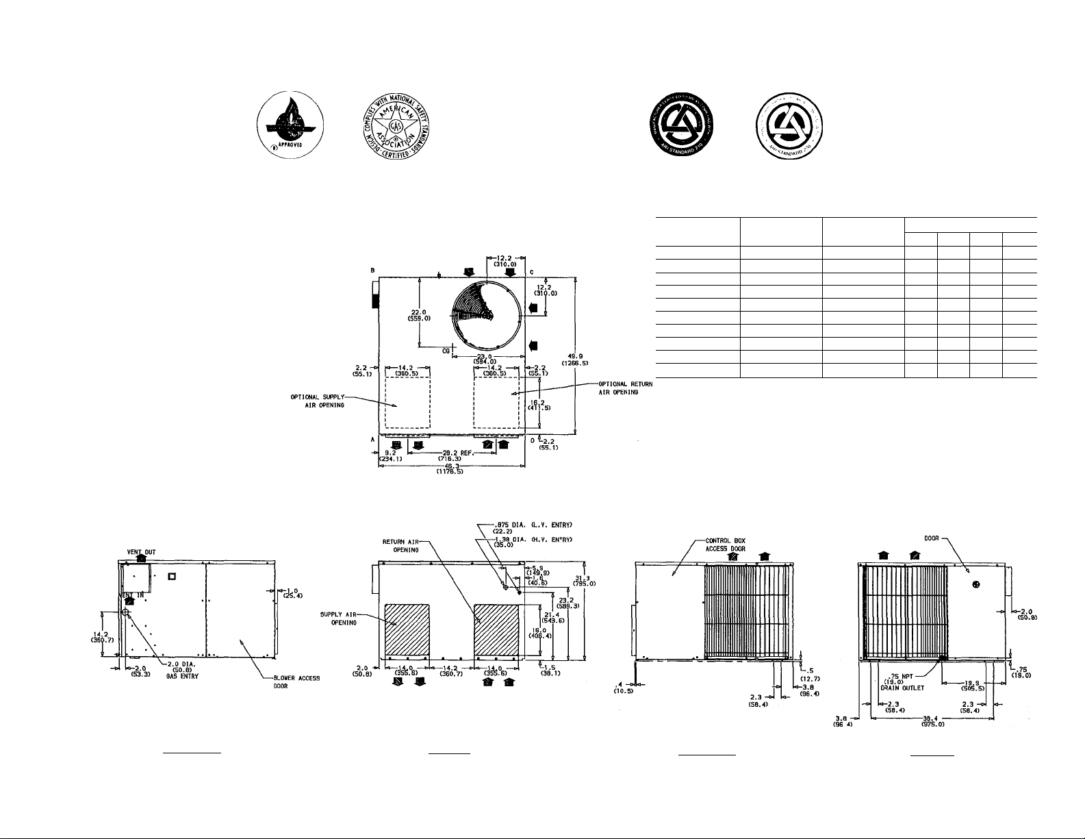
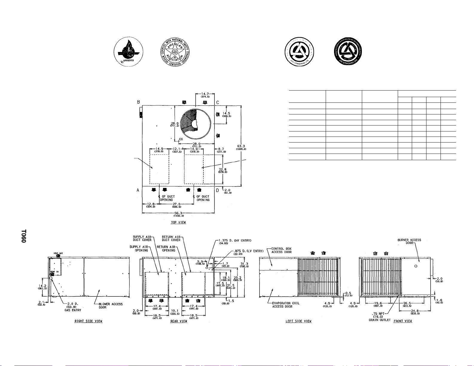
4. Refer to the 48N dimensional drawing for locations of
gas inlet, electrical inlets, condensate drain, duct con
nections, and required clearances before setting unit in
place. Figs. 2 and 3.
5. Locate the unit where the vent cap will be a minimum
of 4-ft from openable windows or doors.
6. This installation must conform with local building
codes and with the National Fuel Gas Code ANSI
Z223.1-1984 and Addenda Z223.la-1987 (In Canada,
CAN/CGA B149.1, (2)-M86) or NFPA 54-1984 TIA-5484-1. Refer to Provincial and local plumbing or
wastewater codes and other applicable local codes.
7. For outdoor installation on wood flooring or on class A,
B, C roof covering materials.
GENERAL
Model 48N Packaged Gas/Electric Unit has been designed
and tested in accordance with ANSI Z21.47-1987, ARI
Standard 210-81, and ARI Standard 270-84, CAN/CGA-2.3M86, CAN 1-2.17-M80, CAN 1-2.21-M85, CSA C22.2 No. 0-
1982, No. 3-1979 and No. 119-M1985. The appliance design
is certified by the American Gas Association (A.G.A.) and
Canadian Gas Association (C.G.A.) for use with natural or
LP (propane) gases with appropriate controls and orifices.
A87316
Tab llalla
Manufacturer reserves the right to discontinue, or change at any time, specifications or designs without notice and without incurring obiigations.
I
^ PC 101 Catalog No. 564-816 Printed in U.S.A. Form 48NT-9SI Pg 1 9-88 Replaces: 48NT-8SI
Page 2
I
IV)
o
a
2--n
Z N)
(/) o
N
(D
(A
^ z
S w
2 >
C
■1^
00
Z
S
H
o
■u
IV)
S
m
D
30
>
z
o
EFFICIENCY
RATING
CERTIFIED
G
ama
Unit Weights
Unit lbs.
48NLT018 47D
48NLT024
48NLT030
48NHT024
48NMT030
48NLT036 506
48NLT042
48NHT030
48NMT036 510
48NMT042
Above unit top
Duct side of unit____6 min. Side opposite blower access panel........30
Side opposite ducts
NOTE: Provision must be made for fresh ambient air to reach the outdoor
coil without recirculation of the air from the outdoor fan discharge.
Shipping Wt. Operating Wt.
474 454
490
480 460
486 476
516 496
500
520
48N REQUIRED CLEARANCES (Inches)
.....................
48 Blower access panel side
.........
30 Bottom of unit
lbs. A
450
470 103
486 107
480 106
490 108
500 110
..........................................
Corner Wt. lbs.
B C D
99
126 126 99
100
127 127 100
132 132 103
101
129 129 101
105 133 133 105
136 136 107
109
139 139 109
134 134 106
137 137 108
140 140 110
......................
BURNER ACCESS
30
0
RIGHT SIDE vmw
REAR VIEW
LEFT SIDE VIEM
FRONT VIFR
Page 3
00
0
Q.
— -n
2 w
1 I
(/) o
n‘ 9
<D S
» m
5 £2
o >
S r-
05
=r 3J
= I
z ^
T o
EFFICIENCY
RATING
CERTIFIED
G
ama
Unit Weights
Shipping Wt.
550
556
594
600
060
624
630
636 616
48N REQUIRED CLEARANCES (Inches)
...................
___
48 Blower access panel side
6 min. Side opposite blower access panel
OPTIONAL SUPPLY-
AIR OPENING
-OPTIONAL RETURN
AIR OPENING
Unit lbs. lbs. A
48NHT036
48NVT036
48NHT042 570 550 122
48NVT042 576
48NLT048
48NMT048
48NHT048
48NLT060
48NMT060
48NHT060
Above unit top
Duct side of unit
Side opposite ducts...........30 Bottom of unit
NOTE: Provision must be made for fresh ambient air to reach the outdoor
coil without recirculation of the air from the outdoor fan discharge.
o
Operating Wt.
530 117
536 119
556 124
574 128
580 130 159 160
586 131 161 162
604
610 138
..........................................
Corner Wt. lbs.
136
139 169 169 140
.......................
B C D
148
147
148 149 120
152 153 123
153
158 159 129
165 166 137
166 167 139
........
154
30
30
0
118
125
131
132
Page 4
This publication contains the following:
Step 1. Moving and Setting Unit in Place
Step
Step
Step
Step
Step
Step
Step
Step
Step 10.
Step 1—Moving and Setting Unit in Place
Condensate Disposal
Venting
Gas Piping
Duct Connections
Electrical Connections
7. Preparing Unit for Steurtup
8. Heating Section Startup and Adjustments
9. Cooling Section Startup and Adjustments
Care and Maintenance
A CAUTION
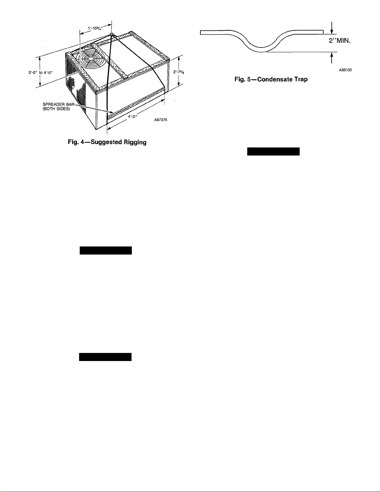
Use spreader bars and crate top when rigging the unit
to be lifted. Model 48N must be rigged for lifting as
shown in Fig. 4. Use extreme caution to prevent dam
age when moving the unit. Unit must remain in an
upright position during eJl rigging and moving opera
tions. The unit must be level for proper condensate
drainage; therefore, the ground-level pad or accessory
roof-mounting curb must be level before setting the
unit in place. When a field-fabricated support is used,
ensure that the support is level and properly supports
the unit.
A. Rooftop installation
A CAUTION
When installing the unit on a rooftop, be sure that the
roof will support the additional weight. Refer to Figs. 2
& 3 for Model 48N to obtain toted weight and corner
weight information.
For downflow applications, an accessory roof-mounting
curb must be installed on, and flashed into the roof before
unit installation. The instructions for installing the acces
sory curb are packaged with the curb.
For end-discharge applications place the unit on a level base
that provides proper support. On flat roofs, be sure that the
unit is located at least 4-ins. above the highest expected
water level on the roof to prevent flooding.
B. Ground-Level Installation
Place the unit on a sohd, level, concrete pad that is a mini
mum of 2-ins. thick and that extends approximately 2-in.
beyond the casing on all four sides of the unit. Do not secure
the unit to the pad except when required by local codes.
C. Clearances
The required minimiim operating and service clearances are
shown in Figs. 2 and 3. Adequate combustion, ventilation
and condenser air must be provided.
A CAUTION
Do not restrict condenser airflow. An air restriction at
either the outdoor-air inlet (the entire surface of the out
door cofl.) or the fan discharge can be detrimental to
compressor hfe.
The condenser fan discharges through the top of the unit.
Ensure that the fan discheirge does not recirculate to the
condenser coil. Do not locate the unit in either a corner or
under a complete overhead obstruction. The minimum clear
ance under a partial overhang (such as a normal house roof
overhang) is 48-ins. above unit top. The maximum horizon
tal extension of a partial overhang must not exceed 48-in..
Do not locate the unit where water, ice, or snow from an
overhang or roof wiU damage or flood the unit by falling on
the top. Do not locate the unit where grass, shrubs, or other
plants will interfere with the airflow either into or out of the
unit. Do not install the unit on carpeting, tile, or other com
bustible material other than wood flooring. Furnace may be
installed on wood flooriag or on Class A, B, or C roof cover
ing materials.
Step 2—Condensate Disposal
NOTE: Ensure that condensate-water disposal methods
comply with local codes, restrictions, and practices.
Model 48N disposes of condensate water through a 3/4-in.,
Male Female NPT drain fitting. See Figs. 2 and 3 for
location.
Install a 2-in. trap at the drain fitting to ensure proper
drainage. See Fig. 5. Make sure that the outlet of the trap is
at least 1-in. lower than the unit drain pan connection to
prevent the pan from overflowing. Prime the trap with
water.
If the installation requires draining the condensate water
away from the unit, connect a drain tube using a minimum
of 7/8-in. OD copper tubing, 3/4-in. galvanized pipe, or
3/4-in. plastic pipe. Do not undersize the tube. Pitch the
drain tube downward at a slope of at least 1-in. in every 10ft of horizontal run. Be sure to check the drain tube for
leaks.
Condensate water can be drained directly onto the roof in
rooftop installations (where permitted) or onto a gravel
apron in ground-level installations. When using a gravel
apron, make sure it slopes away from the unit.
Step 3—Venting
The vent-cap assembly is shipped in the burner compart
ment. Remove the access door to locate the assembly.
Page 5
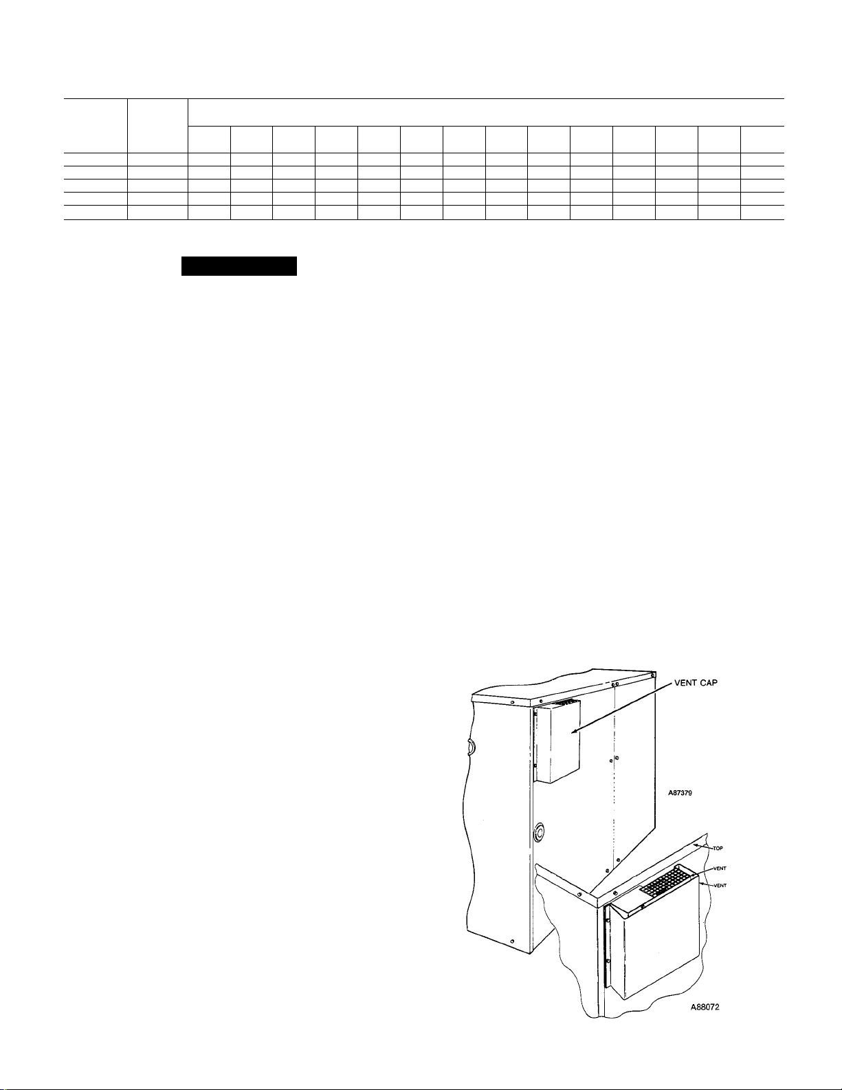
Table 1—Maximum Gas Flow Capacity of Pipe in Cubic Feet of Gas Per Hour for Gas
Pressures of 0.5 PSIG or Less and a Pressure Drop of 0.5 inch Water Coiumn
(Based on a 0.60 Specific Gravity Gas)
Nominal
Iron Pipe,
Size,
Inches
1/2 .622
3/4
1
1-1/4
1-1/2
Ref: Table 0^4, NFPA 54—1984
*This length includes an ordinary number of fittings.
Internal
Diameter,
Inches
.824
1.049
1.380
1.610
10 20 30 40 50 60 70 80 90
175 120 97 82 73 66
360 250
680 455 375 320 285 260 240 220 205 195 175 160 145
1,400 950 770 600 580 530 490 460 430 400 360 325 300 280
2,100 1,460 1,180 990 900 810
170 151 138
200
A CAUTION
The venting system is designed to ensure proper vent
ing. The vent cap assembly must be installed as indi
cated in this section of the unit Installation
Instructions.
NOTE: Screw holes in the flue assembly and the unit flue
panel are not symmetrically located; thereby, ensuring
proper orientation when installing these components.
Refer to Fig. 6 and install the vent cap as follows:
1. Place vent cap assembly over flue panel, orient screw
holes in vent cap with holes in flue panel, and secure
vent cap in place by inserting the single screw on the
right side of vent cap.
2. Place the vent cap guard over the vent cap, orient holes
in vent cap guard with holes in vent cap and flue panel.
Secure the entire assembly with the remaining two
screws on the left side of vent cap and vent cap guard
assembly.
Step 4—Gas Piping
The gas supply pipe enters the unit through the access hole
provided. The gas connection to the unit is made to the
1/2-in. FPT gas inlet on the manual shutoff or gas valve.
Install a separate gas supply line that runs directly from
the meter to the heating section. Refer to Table 1 and the
National Fuel Gas Code for gas pipe sizing. Do not use cast-
iron pipe. Check the local utihty for recommendations con
cerning existing lines. Choose a supply pipe that is large
enough to keep the pressure loss as low as practical. Never
use pipe smaller than the 1/2-in. FPT gas inlet on the unit
gas valve.
When instaUing the gas supply hne, observe local codes per
taining to gas pipe installations. Refer to the National Fuel
Gas Code ANSI Z223.1-1984 (In Canada, CAN/CGA
B 149.1, (2)-M86) or NFPA 54-1984 in the absence of local
buUding codes. Adhere to the following pertinent recom
mendations:
1. Avoid low spots in long runs of pipe. Grade aU pipe
1/4-in. in every 15-ft to prevent traps. Grade all hori
zontal runs downward to risers. Use risers to connect
to heating section and to meter.
2. Protect all segments of piping system against physical
and thermal damage. Support all piping with appropri
ate straps, hangers, etc. Use a minimum of one hanger
every 6-ft. For pipe sizes larger than 1/2-in., follow rec
ommendations of national codes.
3. Apply joint compound (pipe dope) sparingly and only
to male threads of joint when making pipe connections.
Use only pipe dope that is resistant to action of lique
fied petroleum gases as specified by local and/or
national codes. Never use teflon tape.
Length of Pipe, Feet*
200
— —
135
61
125
750
100 125
57
118
690 650 620 550 500 460 430
53 50 44
110 103 93
150 175
40
84 77 72
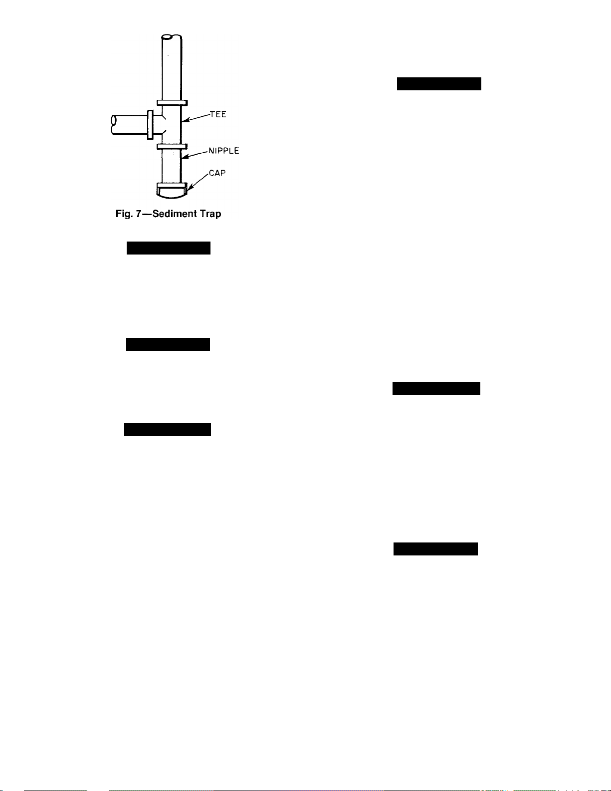
4. Install sediment trap in riser leading to heating sec
tion. This drip leg functions as a trap for dirt and con
densate. Install trap where condensate can not freeze.
Install this sediment trap by connecting a piping tee to
riser leading to heating section, so that straightthrough section of tee is vertical. See Fig. 7. Then, con
nect capped nipple into lower end of tee. Extend
capped nipple below level of gas controls.
Install an accessible, external, manual main shut-off
5.
valve in gas supply pipe within 6-ft of heating section.
Install ground-joint union close to heating section
6.
between unit manual shutoff and external manual main
shut-off valve.
7. Pressure-test all gas piping in accordance with local
and national plumbing and gas codes before connecting
piping to unit.
NOTE: When pressure testing the gas supply system after
the gas supply piping has been coimected to the unit gas
valve, the supply piping must be disconnected from the gas
vedve during any pressure testing of the piping systems at
test pressure in excess of 0.5 psig. When pressure testing
the gas supply piping system at test pressures equal to or
less than 0.5 psig, the unit heating section must be isolated
from the gas piping system by closing the external main
manual shut-off valve and slightly opening the ground-joint
union.
Fig. 6—Vent Cap Assembly
Page 6
A73130
A CAUTION
Unstable operation may occur when the gas valve and
manifold assembly are forced out of position while con
necting improperly routed rigid gas piping to the gas
valve. Use a backup wrench when making connection to
avoid strain on, or distortion of, the gas control piping.
A CAUTION
If a flexible conductor is required or allowed by the
authority having jurisdiction, black iron pipe shall be
installed at the gas valve and extend a minimum of
2-ins. outside the unit casing.
A WARNING
Never use a match or other open flame when checking
for gas leaks. Never purge gas line into combustion
chamber. Failure to adhere to this warning could result
in an explosion.
8. Check for gas leaks at all field-installed and factoryinstalled gas lines after all piping connections have
been completed. Use soap-and-water solution (or
method specified by local codes and/or regulations).
2. Select and size ductwork, supply-air registers, and
return-air grilles according to ASHRAE recom
mendations.
A CAUTION
When the duct-system fastening holes are being drilled
into side of Model 48N instead of the unit duct flanges,
use extreme ceire to avoid puncturing the coil or cofl.
tubes.
3. Use flexible transition between rigid ductwork and unit
to prevent transmission of vibration. The transition
may be screwed or bolted to duct flanges. Use suitable
gaskets to ensure weather and airtight seal.
4. Install external, field-supplied air filter(s) in return-air
ductwork where it is easily accessible for service. Rec
ommended filter sizes are shown in Tables 2 thru 7.
5. Size aU ductwork for maximum required airflow (either
heating or cooling) for unit being installed. Avoid
abrupt duct size increases or decreases.
6. Adequately insulate and weatherproof all ductwork
located outdoors. Insulate ducts passing thru uncondi
tioned space, and use vapor barrier in accordance with
latest issue of SMACNÀ and ACCA minimum installa
tion standards for heating and air conditioning sys
tems. Secure aU ducts to building structure.
7. Flash, weatherproof, and vibration-isolate all openings
in building structure in accordance with local codes and
good building practices.
Step 6—Electrical Connections
A WARNING
The unit cabinet must have an uninterrupted, unbro
ken, electrical ground to minimize the possibility of per
sonal injury if an electrical fault should occur. This
ground may consist of electrical wire connected to the
unit ground lug in the control compartment, or conduit
approved for electrical ground when installed in accor
dance with the National Electrical Code ANSI/NFPA
70-1987 (in Canada, Canadian Electrical Code CSA
C22.1) and local electrical codes. Do not use gas piping
as an electrical ground. A failure to adhere to this warn
ing could result in the installer being hable for the per
sonal injury of others.
Step 5—Duct Connections
Model 48N has duct flanges on the supply- and return-air
openings on the side and bottom of the unit. See Figs. 2 and
3 for connection sizes emd locations.
NOTE: The design and installation of the duct system must
be in accordance with the standards of the National Fire
Protection Association for installation of nonresidence-type
air conditioning and ventilating systems, NFPA No. 90A or
residence-type, NFPA No. 90B; and/or local codes and
ordinances.
Adhere to the following criteria when selecting, sizing, and
installing the duct system:
1. Remove appropriate panels from unit to obtain either
side or bottom discharge. If models 48NLT018 thru
48NMT042 are installed in horizontal discharge apphcations, remove side duct covers, save screws, and
install the covers on bottom duct openings. For models
48NHT036 thru 48NHT060 remove either side or bot
tom duct covers as needed and discard.
A CAUTION
A failure to follow these precautions could result in
damage to the unit being installed:
1. Make all electrical connections in accordance with
National Electrical Code ANSI/NFPA 70-1987 and
local electrical codes governing such wiring. In Canada,
all electrical connections must be in accordance with
CSA standard C22.1 Cemadian Electrical Code Part 1
and applicable local codes. Refer to Unit Wiring
Diagram.
2. Use only copper conductor for connections between
field-supplied electrical disconnect switch and unit. DO
NOT USE ALUMINUM WIRE.
3. Ensure that high-voltage power to unit is within oper
ating voltage range indicated on unit rating plate. On
3-phase units, ensure that phases are balanced within
2%. Consult local power company for correction of
improper voltage and/or phase balance.
Page 7
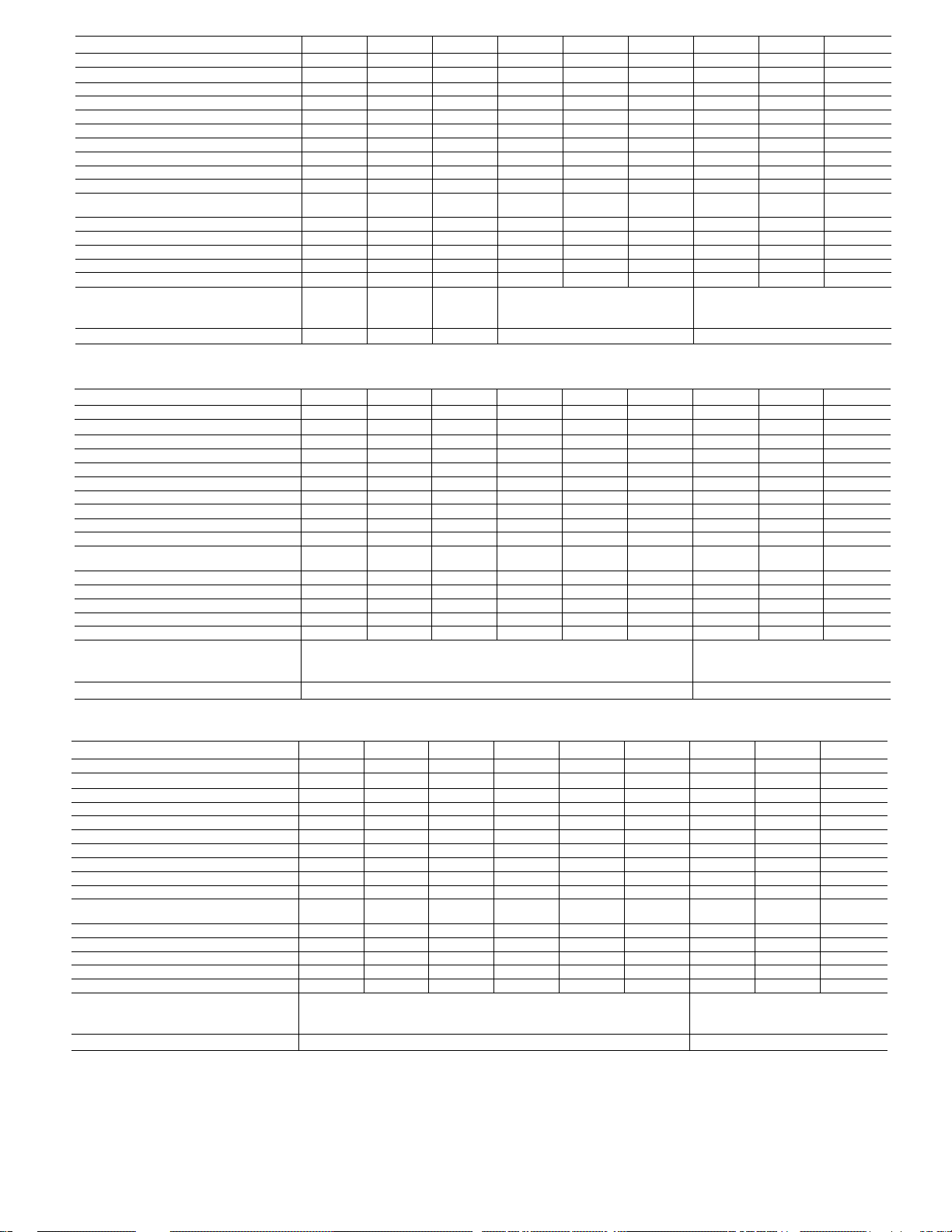
Table 2—Specifications—Models 48N (Sizes NLT018300 thru NLT036600)
MODEL 48N
SIZE
Unit Volts—Phase (60 Hz)
Operating Voltage Range
Unit Full Load Amps
Maximum Fuse Size (Amps)
Minimum Ampacity for Wire Sizing*
Minimum Wire Size (75 C Copper)
Maximum Wire Length (Ft.)
Cooling Capacity (Btuh)t
Rated Cooling Airflow (cfm)t
External Static Pressure (In.
water)t
ARI Sound Rating^
Rated Heating Input (cfm)
Output Capacity (Btuh)**
AFUE(%)**
Rated Heating Airflow (cfm)
Recommended Minimum Field-
Supplied Filter Size (Sq ln.)tt
Disposable-Type
Cleanable- or High-Capacity Type
LT018300 LT024300
208/230—1 208/230—1
187—253
(Applicable notes are listed below Table 4.)
48N 48N
HT024300 LT030300 MT030300
48N 48N
HT030300
208/230—1 208/230—1 208/230—1 208/230—1
11.5
187—253
14.2
187—253 187—253 187—253 187—253
14.2
16.8 16.8 17.3
20 25 25 30 30
13.6 17.1 17.1 20.4 20.4
14
60 70
17,800 23,800 23,800 29,000 29,000
600
0.10
7.8
40,000 40,000 60,000 40,000
31,000 31,000 46,000
12 12
70
10 10 10 10
100 100 100 75
29,000
800 800 1100 1100 1100 1300 1300
0.10 0.10 0.15 0.15 0.15 0.15 0.15
8.0 8.0 8.0 8.0 8.0 8.0 8.0
60,000 80,000 60,000 60,000 60,000
31,000 46,000 61,000 46,000 48,000
77.5 77.5 77.5 77.5 77.5 77.5
658 658 740 658
288
192 256
384 384 528
256 352
740 987
48N
30
20.7
48N 48N
LT036300 LT036500
208/230—1
187—253
208/230—3
187—253 414—506
21.2 14.6
40 25
26.9
18.6
12
65
35,200 35,200
77.5
—
987 987 987
624
416
48N
LT036600
460—3
7.7
15
9.0
14
110
35,200
1300
0.15
8.0
48,000
—
Table 3—Specifications—Models 48N (Sizes MT036300 thru VT036600)
MODEL
SIZE
Unit Volts—Phase (60 Hz)
Operating Voltage Range
Unit Full Load Amps
Maximum Fuse Size (Amps)
Minimum Ampacity for Wire Sizing*
Minimum Wire Size (75 C Copper)
Maximum Wire Length (Ft.)
Cooling Capacity (Btuh)f
Rated Cooling Airflow (cfm)f
External Static Pressure (In.
water)t
ARI Sound Ratingf:
Rated Heating Input (cfm)
Output Capacity (Btuh)**
AFUE(%)**
Rated Heating Airflow (cfm)
Recommended Minimum FieldSupplied Filter Size (Sq ln.)tt
Disposable-Type
Cleanable- or High-Capacity Type
48N 48N
MT036300
MT036500 MT036600 HT036300
48N 48N 48N
208/230—1 208/230—3 460—3
187—253
21.2 14.6
40
26.9
10
75
35,200
1300
0.15 0.15
8.0
80,000
61,000
77.5
187—253 414—506
7.7
25 15
18.6 9,0
12 14 41
65 110
35,200 35,200 35,800
1300 1300
0.15 0.15 0.15 0.15
8.0 8.0 8.0
80,000 80,00 100,0000
64,000 64,000 78,000
__
—
987 987 987 1481
624
416
HT036500 HT036600
208/230—1 208/230—3
48N
460—3 208/230—1
187—253 187—253 414—506
22.4 16.8 8.5 '
40 25 15
26.2 19.3 9.8
12 12
60 70 70
35,800 35,800
1300 1300 1300
8.0 8.0
100,000 100,000
80,000 80,000
77.5
—
— 77.5
1481 1481
48N 48N
VT036300
VT036500 VT036600
208/230—3
187—253
187—253 414—506
22.4 16.8
40
26.2
25
19.3 9.8
10 10
100
35,800
1300
0.15
8.0
100
35,800 35,800
1300 1300
0.15
8.0 8.0
120,000 120,000
93,000 96,000
—
1367
1367 1367
624
416
(Applicable notes are listed below Table 4.)
Table 4—Specifications-
MODEL
SIZE
Unit Volts—Phase (60 Hz)
Operating Voltage Range
Unit Full Load Amps
Maximum Fuse Size (Amps)
Minimum Ampacity for Wire Sizing*
Minimum Wire Size (75 C Copper)
Maximum Wire Length (Ft.)
Cooling Capacity (Btuh)t
Rated Cooling Airflow (cfm)f
External Static Pressure (In.
water)t
ARI Sound Rating^:
Rated Heating Input (cfm)
Output Capacity (Btuh)**
AFUE(%)**
Rated Heating Airflow (cfm)
Recommended Minimum FieldSupplied Filter Size (Sq ln.)ft
Disposable-Type
Cleanable- or High-Capacity Type
48N
LT042300
208/230—1
187—253
24.6 16.0
50
31.1
8
95
41,500
1500 1500
0.15 0.15
7.8 8.0
60,000 60,000
46,000 48,000 48,000
77.5
987
- Models 48N (Sizes LT042300 thru HT042600)
48N 48N 48N
LT042500 LT042600 MT042300
208/230—1 460—3
208/230—1 208/230—3
187—253 414—506 187—253
8.8 24.6
30
15 50 30
20.4 10.3 31.1
10
100 100
14 8 10
95 100 100
41,500 41,500 41,500
1500 1500
0.15 0.15 0.15 0.15
8.0 8.0
60,00 80,000 80,000
61,000 64,000 64,000
—
987
—
77.5
987 987 987 987
720
480
48N 48N
MT042500
MT042600 HT042300
460—3 208/230—1
187—253 414—506
16.0 8.8
2.4 10.3
41,500 41,500
1500 1500 1500
8.0 8.0
80,000 100,000
-
48N
187—253
26.7
15 45
31.7
14 10
75
41,500 41,500
0.15
8.2 8.2
_
78,000
77.5
1481 1481
48N 48N
HT042500
208/230—3
187—253
18.2 9.6
30
21.1
12
65 110
1500
0.15
100,000
80,000 80,000
— —
720
480
*lf other than 75 C copper wire is used, determine size from unit ampacity and the National Electrical Code. Voltage drop of wire must be less than 2%
of unit rated voltage.
tRated in accordance with U.S. Government D.O.E. test procedures and/or ARI Standard 210.
tRated in accordance with ARI Standard 270.
**The capacity ratings of single-phase units are in accordance with U.S. Government D.O.E. test procedures and/or A.G.A. certification requirements. For
3-phase units, the efficiency rating is a product thermal efficiency rating determined under continuous operating conditions, independent of any
installed system.
ttRequired filter areas shown are based on the larger of the ARI-rated cooling airflow or the heating airflow at a velocity of 300 ft/min for disposable type
or 450 ft/min for high-capacity type. Air filter pressure drop must not exceed 0.08 in.-water.
48N
460—3
8.5
15
10
100
0.15
120,000
96,000
—
HT042600
460—3
414—506
15
11.1
14
41,500
1500
0.15
8.2
100,000
1481
Page 8
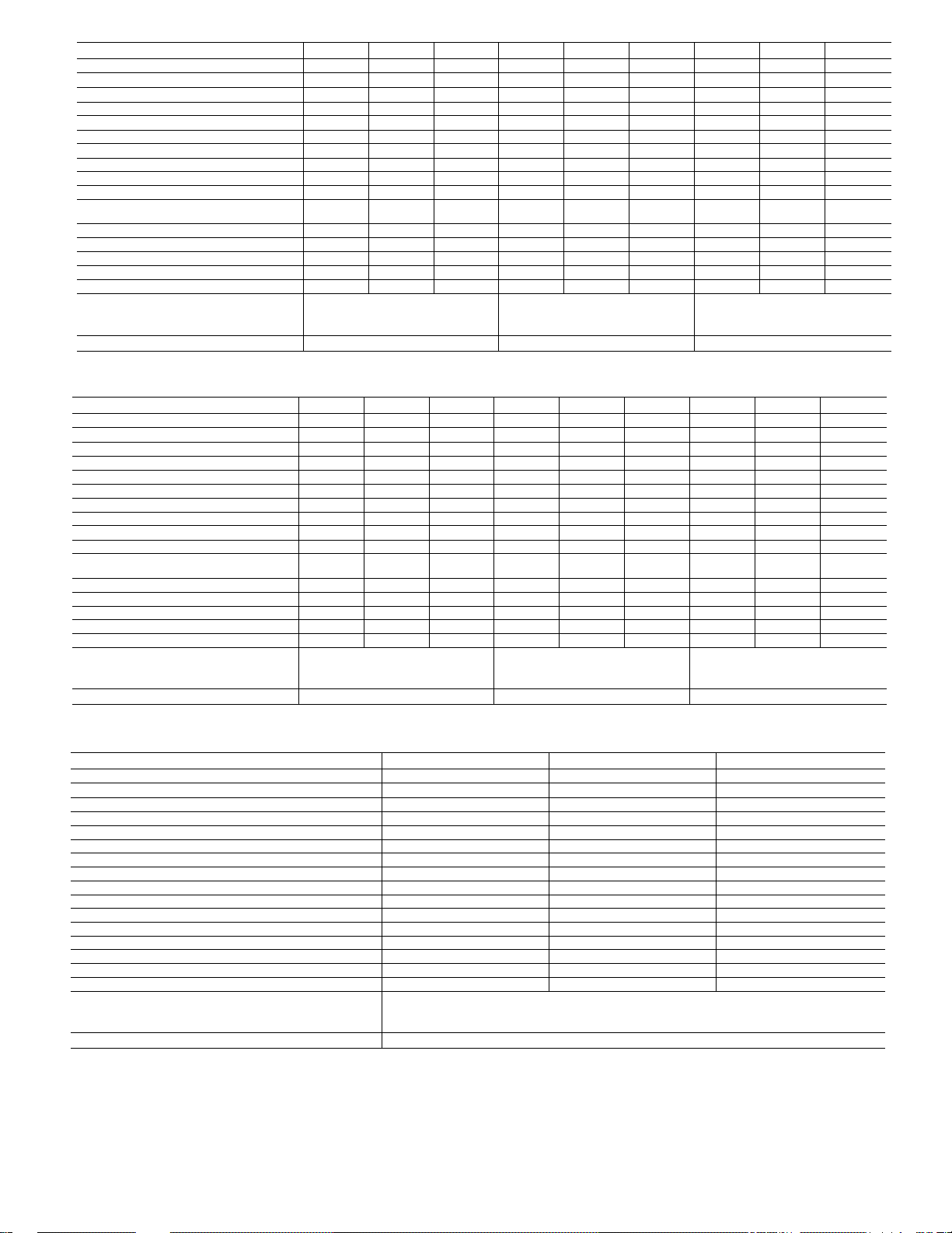
Table 5—Specifications—Models 48N (Sizes VT042300 thru MT048600)
MODEL 48N 48N 48N 48N
SIZE VT042300
Unit Volts—Phase (60 Hz)
Operating Voltage Range
Unit Full Load Amps
Maximum Fuse Size (Amps)
Minimum Ampacity for Wire Sizing*
Minimum Wire Size (75 C Copper) 10 12
Maximum Wire Length (Ft.)
Cooling Capacity (Btuh)f
Rated Cooling Airflow (cfm)f
External Static Pressure (In.
water)t
ARI Sound Rating^:
Rated Heating Input (cfm)
Output Capacity (Btuh)** 93,000 96,000 96,000
AFUE(%)** 77.5
Rated Heating Airflow (cfm)
Recommended Minimum Field-
Supplied Filter Size (Sq ln.)tt
Disposable-Type
Cleanable- or High-Capacity Type 480 544
208/230—1 208/230—3 460—3 208/230—1
187—253 187—253 414—506
26.7
45 30 15
31.7
75
41,500
1500
0.15 0.15 0.15
8.2
120,000
1367 1367 1367
VT042500 VT042600 LT048300
187—253 187—253
18.2 9.6 27.2
50 40 20
21.1
65
11.1 32.7
14
8
110 95
41,500 41,500 47,500
1500 1500 1700
0.20
8.2
8.2
8.2
120,000 120,000 80,000
62,000 64,000 48,000
—
—
77.5
1481
720 816
(Applicable notes are listed below Table 7.)
48N
LT048500
208/230—3
22.1
26.0 13.1
10
100
47,500
1700 1500
0.20
8.2
80,000
— —
1481
48N
LT048600
460—3
414—506
11.0
14
100
47,500
0.15
8.2
60,000
1481
48N
MT048300
208/230—1
187—253 187—253 414—506
27.5 22.1 11.0
50
32.7 26.1 13.1
8 10 14
95
47,500
1700
0.20 0.20 0.20
8.2 8.2 8.2
100,000 100,000 100,000
78,000
77.5
1481 1481 ,1481
48N 48N
MT048500
MT048600
208/230—3
40 20
100 100
47,500
47,500
1700 1700
80,000 80,000
— —
816
544
460-3
Table 6—Specifications—Models 48N (Sizes HT048300 thru MT060600)
MODEL
SIZE
Unit Volts—Phase (60 Hz)
Operating Voltage Range
Unit Full Load Amps
Maximum Fuse Size (Amps)
Minimum Ampacity for Wire Sizing*
Minimum Wire Size (75 C Copper)
Maximum Wire Length (Ft.) 75 65
Cooling Capacity (Btuh)t
Rated Cooling Airflow (cfm)t
External Static Pressure (In.
water)t
ARI Sound Ratingf:
Rated Heating input (cfm)
Output Capacity (Btuh)**
AFUE (%)** 77.5
Rated Heating Airflow (cfm)
Recommended Minimum FieldSupplied Filter Size (Sq ln.)tt
Disposable-Type
Cleanable- or High-Capacity Type
48N
HT048300
48N 48N
HT048500 HT048600
208/230—1 208/230—3 460—3 208/230—1 208/230—3 460—3
187—253 187—253 414—506 187—253 187—253 414—506
27.5 22.1 11.0 40.8 31.6 14.6
50
32.7
26.0 13.1 48.5 37.0
10 12 14 8 10 14
47,500 47,500 47,500 59,500 59,500 59,500
1700
1700
0.20 0.20
8.2 8.2 8.2 8.4 8.4 8.4
120,000
120,000
93,000 96,000 96,000
1367 1367 1367 1481 1481 1481
816 960
544
40
20 60 50 25
110 95 100 100
1700 2000 2000 2000
0.20 0.20
120,000 80,000
_
—
48N
LT060300 LT060500 LT060600
48N 48N
17.2 48.5
0.20 0.20
80,000 100,000
—
62,000
77.5
0.20
80,000
64,000 64,000
—
640
48N
MT060300 MT060500 MT060600
208/230—1
187—253
40.8
60 50 25
8 10
95 100 100
59,500 59,500 59,500
2000 2000 2000
8.4
78,000
77.5
1646 1646 1646
(Applicable notes are listed below Table 7.)
Table 7—Specifications-
MODEL
SIZE HT060300
Unit Volts—Phase (60 Hz) 208/230—1 208/230—3
Operating Voltage Range
Unit Full Load Amps
Maximum Fuse Size (Amps) 60 50
Minimum Ampacity for wire Sizing* 48.5 37.0
Minimum Wire Size (75 C Copper)
Maximum Wire Length (Ft.) 75 65
Cooling Capacity (Btuh)t
Rated Cooling Airflow (cfm)t
External Static Pressure (in. water)t
ARI Sound Ratingt
Rated Heating Input (Btuh)**
Output Capacity (Btuh)** 93,000 96,000 96,000
AFUE(%)** 77.5
Rated Heating Airflow (cfm)
Recommended Minimum Field-
Supplied Filter Sizeft
Disposable-Type
Cleanable- or High-Capacity Type 640
- Models 48N (Sizes HT060300 thru HT060600)
48N 48N
187—253
40.8 31.6
10 12
59,500 59,500
2000 2000
0.20 0.20
8.4 8.4
120,000
1975 1975
HT060500 HT060600
187—253 414—506
120,000
— —
960
*lf other than 75 C copper wire is used, determine size from unit ampacity and the National Electrical Code. Voltage drop of wire must be less than 2%
of unit rated voltage.
fRated in accordance with U.S. Government D.O.E. test procedures and/or ARI Standard 210.
tRated in accordance with ARI Standard 270.
**The capacity ratings of single-phase units are in accordance with U.S. Government D.O.E. test procedures and/or A.G.A. certification requirements. For
3-phase units, the efficiency rating is a product thermal efficiency rating determined under continuous operating conditions, independent of any
installed system.
ttRequIred filter areas shown are based on the larger of the ARI-rated cooling airflow or the heating airflow at a velocity of 300 ft/min for disposable type
or 450 ft/mln for hIgh-capacIty type. Air filter pressure drop must not exceed 0.08 in.-water.
48N 48N
208/230—3 460-3
187—253
31.6
414—506
14.6
37.0 17.2
14
0.20 0.20
8.4
8.4
100,000 100,000
80,000
— —
80,000
960
640
48N
460—3
14.6
25
17.2
14
110
59,500
2000
0.20
8.4
120,000
1975
8
Page 9

4. Insulate low-voltage wires for highest voltage con
tained within conduit when low-voltage control wires
are run in same conduit as high-voltage wires.
5. Do not deunage internal components when drilling thru
any panel to mount electrical hardware, conduit, etc.
A. High-Voltage Connections
The unit must have a separate electrical service with a field-
supphed, waterproof, fused disconnect switch mounted at,
or within sight from the unit. Refer to the unit rating plate
for maximum fuse size and minimum circuit amps (ampac
ity) for wire sizing. Tables 2 thru 7 show recommended wire
sizes based on rating plate data.
The field-supphed disconnect switch box may be mounted
on the unit over the high-voltage inlet hole in the control
corner panel. See Figs. 2 and 3.
Proceed as follows to complete the high-voltage connections
to the unit:
1. Connect ground lead to chassis ground connection
when using separate ground wire.
2. Run high-voltage leads into unit control box and con
nect to contactor. See unit wiring label, and Fig. 8.
B. Special Procedures for 208-V Operation
A WARNING
Make sure that the power supply to the unit is switched
OFF before making any wiring changes. Electrical
shock can cause personal injury or death.
For operation on 208 volts, disconnect the orange
transformer-primary lead from the contactor. See the unit
wiring label. Remove the tape and cover from the terminal
on the end of the red transformer-primary lead. Save the
cover. Connect the red lead to the contactor terminal from
which the orange lead was disconnected.
Using the cover removed from the red lead, insulate the
loose terminal on the orange lead. Wrap the cover with elec
trical tape so that the metal terminal can not be seen.
Indoor blower motor speed taps should be changed for 208V
operation on 208/230v rated units. Interchange motor leads
at printed circuit board (PCI) in unit control box. High
speed for coohng and medium speed for heating operation.
See Step 9-C and unit wiring label. Do not change blower
speed setting for 460V rated units.
C. Control Voltage Connections
Locate the room thermostat on an inside wall in the space
to be conditioned where it will not be subjected to either a
coohng or heating source or direct exposure to sunhght.
Mount the thermostat 4 to 5-ft above the floor.
Use No. 18 AWG color-coded, insulated (35 C minimum)
wires to make the control voltage connections between the
thermostat and the unit. If the thermostat is located more
than 100-ft from the unit (as measured along the control
voltage wires), use No. 16 AWG color-coded, insulated (35 C
minimum) wires.
A grommeted, control voltage inlet hole is located in the
panel adjacent to the control access panel. See Figs. 2 and 3.
Run the low-voltage leads from the thermostat, thru the
inlet hole, and to the control voltage terminals through a
hole in the bottom of the unit control box. Pass control volt
age leads through wire ties located under unit control box.
Connect the thermostat leads to the terminals as shown in
Fig. 8.
D. Heat Anticipator Setting
The room thermostat heat anticipator must be properly
adjusted to ensure proper heating performance. Set the heat
anticipator, using an ammeter to determine the exact
required setting.
NOTE: For thermostat selection purposes, use 1.0 amp for
the approximate required setting.
THERMOSTAT (TYPICAL)
-TERMINAL BOARD
rCONTACTOR TERMINALS
(SEE UNIT WIRING LABEL)
©5^
CONTROL BOX
• FIELD CONTROL-VOLTAGE WIRING
' FIELD HIGH-VOLTAGE WIRING
Fig. 8—High and Control Voltage Connections
Failure to make a proper heat anticipator adjustment will
result in improper operation, discomfort to the occupants of
the conditioned space, and inefficient energy utilization;
however, the required setting may be changed shghtly to
provide a greater degree of comfort for a particular
installation.
E. Circuit Breaker
Unit has manual reset circuit breaker which is located in the
low voltage wiring box adjacent to low voltage terminal
board. If unit fails to operate, first check breaker for tripped
position. If breaker is tripped, re-set and try to start unit. If
breaker continues to trip there is a problem in the low volt
age electrical circuit. (Electrical short, ground, or trans
former overload) Correct the condition and check for normal
unit operation.
Step 7—Preparing Unit for Startup
DANGER: Failure to observe the following warnings
could result in serious personal injury;
1. Follow recognized safety practices and wear protec
tive goggles when checking or servicing refrigerant
system.
2. Do not operate compressor or provide any electric
power to unit unless compressor termineJ cover is in
place and secured.
3. Do not remove compressor terminal cover until all
electrical sources have been disconnected.
4. Reheve all pressure from system before touching or
disturbing anything inside terminal box if refriger
ant leak is suspected around compressor terminals.
5. Never attempt to repair soldered connection while
refrigeremt system is under pressure.
6. Do not use torch to remove any component. System
contains oil emd refrigerant under pressure. To
remove a component, wear protective goggles and
proceed as follows:
a. Shut off gas supply and then electrical power to
unit.
b. Relieve all pressure from system.
c. Cut component connecting tubing with tubing
cutter and remove component from unit.
d. Carefully unsweat remaining tubing stubs when
necessary. Oil can ignite when exposed to torch
flame.
r
GND
FIELD SUPPLIED
FUSED DISCONNECT
- 3-PHASE
UNITS ONLY
A WARNING
A87380
9
Page 10

A. Prestartup Procedures
Proceed as follows to inspect eind prepare the unit for initial
startup:
1. Remove all access panels.
2. Read and follow instructions on aU WARNING, CAU
TION, and INFORMATION labels attached to, or
shipped with unit.
3. Make the following inspections:
a. Inspect for shipping and handling damages such as
broken lines, loose parts, disconnected wires, etc.
b. Inspect for oil at all refrigerant tubing connections
and on unit base. Detecting oil generally indicates a
refrigerant leak. Leak-test all refrigerant tubing
connections using electronic leak detector, hahde
torch, or hquid-soap solution. If refrigerant leak is
detected, see “Refrigerant Leaks” in the next part
of this section.
c. Inspect aU field- and factory-wiring connections. Be
sure that connections are completed and tight.
d. Inspect coil fins. If damaged during shipping and
handling, carefully stredghten fins with a fin comb.
4. Verify the following conditions:
A WARNING
Do not purge gas supply into the combustion cham
ber. Do not use a match or other open flame to check
for gas leaks. Failure to adhere to this warning could
result in an explosion.
a. Make sure that gas supply has been purged, and
that aU gas piping has been checked for leaks.
b. Make sure that outdoor fan blade is correctly posi
tioned in fan orifice. Blades should clear fan motor
by no more than 1/4-in..
c. Make sure that air filter(s) is in place.
d. Make sure that condensate drain pan is filled with
water to ensure proper drainage.
e. Make sure that all tools and miscellaneous loose
parts have been removed.
Unit is now ready for initial startup.
B. Refrigerant Leaks
Proceed as foUows to repair a refrigerant leak and to charge
the unit:
1. Locate leak and ensure that refrigerant system pres
sure has been relieved.
2. Repair leak following accepted practices.
NOTE: Install a filter-drier whenever the system has been
opened for repair.
3. Add a small charge of R-22 refrigerant vapor to system
and leak-test unit.
4. Evacuate refrigerant system if additional leaks are not
found.
5. Charge unit with R-22 refrigerant, using a volumetric-
charging cylinder or accurate scale. Refer to unit rating
plate for required charge. Be sure to add extra refriger
ant to compensate for internal volume of filter-drier.
NOTE: See Step 9, part B for checking and adjusting refrig
erant charge.
Step 8—Heating Section Startup and Adjustments
A CAUTION
Complete the required procedures given in Step 7, '
paring Unit for Startup,” before starting the unit.
‘Pre-
Do not jumper any safety devices when operating the unit.
Ensure that burner orifices are properly aligned. Unstable
operation may occur when the burner orifices in the mani
fold are misaligned.
NOTE: When installing a unit in extremely cold chmate
areas, a run-in period for the inducer motor is recom
mended. After the unit has been installed disconnect the red
wire from terminal 2 at the ignition control (IGN) and
jumper terminals R-W at the control voltage termineJ
board. See Figs. 12, 13, & 14. The inducer motor should run
but burner ignition will not occur. Allow inducer motor to
run for 4 to 5 hours. Reconnect red wire to terminal 2 at
ignition control (IGN) and remove R-W jumper at the con
trol voltage terminal board. Proceed as follows to complete
heating section start up.
Follow the fighting instructions on the heating section oper
ation label (located inside the burner access door) to start
the heating section.
However, when fighting the unit for the first time, perform
the following additional steps:
1. If the gas supply pipe was not purged before connect
ing the unit, it will be full of air. It is recommended
that the ground joint union be loosened, and the supply
fine be allowed to purge until the odor of gas is
detected. Never purge gas fines into a combustion
chamber. Immediately upon detection of gas odor,
retighten the union. Allow 5 minutes to elapse, then
fight unit in accordance with Step 8, part A below.
A. Checking Heating Controi Operation
Start and check the unit for proper heating control opera
tion as follows: (See furnace fighting instructions located
inside burner access panel.)
Place the room thermostat SYSTEM switch in the HEAT
position and the FAN switch in the AUTO position. Set the
heating temperature control of the thermostat above room
temperature. Observe that after built-in time delays, the
pilot automatically fights, the burners fight, and the blower
motor starts. Observe that the burners and pilot go out, and
that after a built-in delay the blower motor stops when the
heating control setting of the thermostat is satisfied.
NOTE: 060 size 460V models are equipped with a 3-phase
blower motor. Check blower wheel for correct rotation as
indicated by arrow on blower housing. If blower wheel
rotates in opposite direction, reverse any two blower motor
leads or any two fine voltage leads. Recheck blower wheel
rotation if necessary to reverse leads.
B. Gas Input
Check gas input and manifold pressure after unit start-up.
(See Table 8) If adjustment is required proceed as follows.
A CAUTION
These units are designed to consume the rated gas
inputs using the fixed orifices at specified manifold
pressures as shown in Table 8. DO NOT REDRILL
THE ORIFICES UNDER ANY CIRCUMSTANCES.
The rated gas inputs shown in Table 8 are for eiltitudes from
sea level up to 2000-ft above sea level. These inputs are
based on natural gas with a heating value of 1050 Btu/ft^ at
0.65 specific gravity, or LP (propane) gas with a heating
value of 2500 Btu/ft^ at 1.5 specific gravity. For elevations
above 2000-ft, reduce input 4% for each 1000-ft above sea
level. When the gas supply being used has a different heat
ing value or specific gravity, refer to national and local
10
Page 11

codes, or contact your Distributor or Branch to determine
the required orifice size.
C. Adjusting Gas Input
The gas input to the unit is determined by measuring the
gas flow at the meter or by measuring the manifold pres
sure. Measuring the gas flow at the meter is recommended
for natural gas units. The manifold pressure must be mea
sured to determine the input of propane gas units.
1. Measuring Gas Flow at Meter Method—Natural Gas
Units
Minor adjustment can be made by changing the manifold
pressure. The manifold pressure must be maintained
between 3.2 and 3.8-in. water. If larger adjustments are
required, change main burner orifices following the recom
mendations of national and local codes.
NOTE: All other apphances that use the same meter must
be turned off when gas flow is measured at the meter.
Proceed as follows:
Turn off gas supply to unit.
a.
Remove pipe plug on outlet of gas valve, then con
b.
nect manometer at this point. Turn on gas to unit.
Record number of seconds for gas meter test dial to
c.
make one revolution.
Divide number of seconds in step c into 3600 (num
ber of seconds in 1 hour).
Multiply result of step d by the number of cubic ft
e.
shown for one revolution of test dial to obtain cubic
ft of gas flow per hour.
f. Multiply result of step e by Btu heating value of gas
to obtain total measured input in Btuh. Compare
this value with heating input shown in Table 8.
(Consult the local gas suppher if the heating value
of gas is not known.)
Example: Assume that the size of test dial is 1 cubic ft, one
revolution takes 30 seconds, eind the heating value of the
gas is 1050 Btu/ft®, then proceed as follows:
a. 30 seconds to complete one revolution.
b. 3600 -30 = 120.
c. 120 X 1 = 120 ft® of gas flow/hr.
d. 120 X 1050 = 126,000-Btuh input.
If the desired gas input is 125,000 Btuh, only a minor
change in the manifold pressure is required.
Observe manifold pressure and proceed as follows to adjust
gas input:
Remove cover screw over regulator adjustment
a.
screw on gas valve.
Turn regulator adjustment screw clockwise to
b.
increase gas input, or turn regulator adjustment
screw counterclockwise to decrease input. Manifold
pressure must be between 3.2 and 3.8-in.-water.
A WARNING
Unsafe operation of the unit may result if manifold
pressure is outside this range. Personal injury or unit
damage may result.
c. Replace cover screw cap on gas valve.
d. Turn off gas supply to unit. Remove manometer
from pressure tap. Replace pipe plug on gas valve.
Turn on gas to unit. Check for leaks.
2. Measuring Manifold Pressure—Propane Gas Units
The main burner orifices on a propane gas unit are sized for
the unit rated input when the manifold pressure is 10.5-in.
water.
Proceed as follows to adjust gas input on a propane gas
unit:
a. Turn off gas to unit.
b. Remove pipe plug on outlet of gas valve then con
nect memometer at this point.
c. Turn on gas to unit.
d. Remove cover screw over REG ADJ screw on gas
valve.
e. Adjust regulator adjustment screw for a manifold
pressure reading of 10.5-in.-water. Turn adjusting
screw clockwise to increase manifold pressure, or
turn adjusting screw counterclockwise to decrease
manifold pressure.
f. Replace cover screw.
g. Turn off gas to unit. Remove manometer from pres
sure tap. Replace pipe plug on gas valve, then tmrn
on gas to unit. Check for leaks.
D. Check Burner Flame
Observe the unit heatmg operation, and watch the burner
flames through the observation port to see if they are light
blue and soft in appearance, and the flames are approxi
mately the same for each burner. See Fig. 10.
E. Blower Heat-Relay Operation
Blower relay PCI (See the unit wiring diagram.) is located in
the control box and adjusts to permit either longer or
shorter “off” cycles. The “on” cycle is factory set for 1 min
ute on timing. The adjusting dial on the relay (See Fig. 9) is
factory-set at the minimum position to provide optimum
performance for most installations. On unusual installa
tions, the length of time the blower remains on may require
increasing. To increase blower operation time, rotate the
adjusting dial counter-clockwise. To decrease blower opera
tion time, rotate dial clockwise. (Minimum time 1 minute.)
Maximum time 3 minutes.)
F. Airflow and Temperature Rise
The heating section of each size of unit is designed and
approved for heating operation within the temperature rise
range stamped on the unit rating plate.
Table 8—Rated Gas Inputs at Indicated Manifold Pressures
Gas Supply Pressure
Number
Model
No.
48NLT018, 024, 030
48NHT024, MT030, LT036, LT042
48NHT030, MT036, MT042, LT048, LT060 4 5.0
48NHT036, HT042, MT048, MT060 5 5.0 13.6 11.0 13.6 3.5
48NVT036, VT042, HT048, HT060 6 5.0 13.6 11.0 13.6 3.5 10.5 5536544 120,000 55365-55 120,000
♦Based on altitudes from sea level up to 2000 feet above sea level. For altitudes above 2000 feet, reduce input rating 4% for each 1000 feet above sea
level. In Canada, from 2000 ft. above sea level to 4,500 ft. above sea level, derate the unit 10%.
fWhen a 48N is converted to propane, the burners must be modified. See kit instructions.
of
Orifices
Min Max Min Max Natural Propane
2 5.0 13.6
3 5.0 13.6 11.0
(in. wc)
Natural Propane
11.0 13.0 3.5 10.5
13.6
11.0 13.0 3.5 10.5 55365-44 80,000 55365-55 80,000
13.0
Manifold
Pressure
(In. wc)
3.5
10.5
12.5
Natural Gas
Orifice
P/N
55365-44
55365-44
55365-44 100,000
Heating
Input
(Btuh)*
40,000 55365-55 40,000
60,000 55365-55 60,000
Propane Gast
Input
P/N
55365-55
Heating
(Btuh)*
100,000
11
Page 12

Table 9 shows the approved temperature rise range for each
unit, and the air delivery Cfm at various temperature rises.
The heating operation airflow must produce a temperature
rise that fedls within the approved range.
Refer to Step 9, part C, of these instructions to adjust heat
ing airflow, when required.
G. Safety Check of Limit Control
The control shuts off the combustion gas supply and ener
gizes the circulating-air blower motor if the furnace
overheats.
The recommended method of checking this hmit control is
to gradually block off the return air after the furnace has
been operating for a period of at least 5 minutes. As soon as
the hmit control functions, the retum-air opening should be
unblocked to permit normal eiir circulation. By using this
method to check the hmit control, it can be estabhshed that
the hmit is functioning properly and the furnace will “fail
safe” if there is a restricted circulating air supply or motor
failure. If the hmit control does not function during this
test, the cause must be determined emd corrected.
H. Heating Sequence of Operation See Figs. 12,13 or 14
Room thermostat cahs for heat closing circuit between “ R”
and “W” 24 volt control circuit terminals. (Power to the
“R” terminal is supphed through “CB” Circuit Breaker and
“LS, ALS Emd FL” safety switches) “PC2” inducer control
board is energized which starts the inducer motor “IM”.
The inducer motor comes up to speed, the vacuum in the col
lector box increases, opening the normahy closed and clos
ing the normahy open contacts of the contacts of the pres
sure switch “PS” energizing the circuit to the “IGN” igni
tion control and the phot valve “PV”. If the flame sensor
proves the presence of the pilot flame the internal switching
of the ingition control de-energizes the spark generator and
energizes the main gas valve, “MV” and the “IFR2” elec
tronic timer. Gas flows to the main burners and is ignited
by the phot flame. The “PCI” electronic timer will close the
“IFR2” relay between 60 to 90 seconds after the burners
are ignited and the blower motor “IFM” will start. When
the thermostat is satisfied the “R” and “W” circuit is
opened and power is removed from the “PC2” inducer con
trol and the “IGN” ignition module which causes the main
gas vedve to close instantly and the inducer motor is de
energized. The electronic timer “PCI” will keep the “IFM”
blower motor running Em additional 1 to 3 minutes. Then
the blower stops and the unit is on standby until another
call for heat.
NOTE: If the main limit switch opens due to the unit over
heating, the blower motor is turned on thru the electronic
board.
If the pilot fails to hght within a 50 second trail for ignition
period from the initial caff for heat the ignition control
“IGN” will lockout the system and prevent further hghting
attempts. To reset, open the “R” - “W” thermostat circuit
for 30 seconds and re-close.
I. Limit Switches
Furnace limit switch “LS” (See Figs. 12, 13 or 14.) closes
the gas valve if the leaving-eur temperature exceeds the
maximum allowable temperature.
Normally closed hmit switch “LS” completes the control
circuit through the thermostat “R” circuit, See Figs. 12, 13
or 14. Should the leaving-air temperature rise above the
maximum allowable temperature the hmit switch opens emd
the “R” control circuit “bresiks.” Any interruption in the
“R” control circuit instantly closes the gas valve and stops
gas flow to the burners and phot. The blower motor contin
ues to run until the time-delay sequence of blower relay
“PCI” is completed.
When the air temperature at the hmit switch drops to the
low-temperature setting of the hmit switch, the switch
closes and completes the “R” control circuit. The electricspark ignition system cycles and the unit retm-ns to normal
heating operation.
J. Auxiliary Limit Switch
Auxihary hmit switch “ALS” is a temperature-actuated
manual reset switch and is connected in series with the hmit
switch “LS.” The function of the switch is to prevent abnor
mal blower compartment temperatures. The switch is
mounted on the blower housing. When the temperature at
the auxihary switch reaches the maximum allowable tem
perature the “R” control circuit “breaks”, closing the gas
valve and stopping gas flow to the burners and pilot. To
reset switch push in on red push button. If it cycles again,
shut down the unit and cah for service.
K. Fusible Link
Fusible Link “FL” is a temperature-actuated device con
nected in series with the hmit switch “LS.” It is located iu
the wire bundle adjacent to the burner manifold.
The function of the device is to prevent abnormaUy high
burner compartment temperatures. The hnk will melt if an
overheating condition caused by inadequate combustion air
supply or improper venting occurs. Do not jumper this fuse.
Correct the condition and replace the fuse with an identical
part.
Step 9—Cooling Section Startup and Adjustments
CAUTION
Complete the required procedures given in Step 7, “Pre
paring Unit for Startup,” before starting the unit.
Do not jumper emy safety devices when operating the
unit.
Do not operate the compressor when the outdoor tem
perature is below 55 F (unless accessory low-temp kit is
installed).
Do not rapid-cycle the compressor. AUow 5 minutes
between “on” cycles to prevent compressor damage.
A. Checking Cooling Control Operation
StEurt and check the unit for proper cooling control operation
as follows:
1. Place room thermostat SYSTEM switch in OFF posi
tion. Observe that blower motor starts when FAN
switch is placed in ON position and shuts down when
FAN switch is placed in AUTO position.
2. Place SYSTEM switch in COOL position and FAN
switch in AUTO position. Set cooling control below
room temperature. Observe that compressor, con
denser fan, and evaporator blower motors start.
Observe that cooHng cycle shuts down when control
setting is satisfied. Blower motor has off delay of
approximately one minute on shut down.
3. When using an autochangeover room thermostat, place
both SYSTEM and FAN switches in AUTO positions.
Observe that unit operates in heating mode when tem
perature control is set to “caU for heating” (above
room temperature) and operates in coohng mode when
temperature control is set to “call for cooling” (below
room temperature).
NOTE: 060 size 460V models are equipped with a 3-phase
12
Page 13

blower motor. Check blower wheel for correct rotation as
indicated by arrow on blower housing. If blower wheel
rotates in opposite direction, reverse any two blower motor
leads or any two line voltage leads. Recheck blower wheel
rotation if necessary to reverse leads.
B. Checking and Adjusting Refrigerant Charge
The refrigerant system is fuUy charged with R-22 refriger
ant, tested, and factory-sealed.
NOTE: Adjustment of the refrigerant charge is not required
unless the unit is suspected of not having the proper R-22
charge. For all appHcations, the correct R-22 charge for the
best performance is the charge that results in a suction gas
superheat of 5 F at the compressor inlet when the unit is
operating at the ARI rating conditions of 95 F DB outdoor
and 80 F DB/67 F WB indoor.
A superheat charging label is attached to the outside of the
compressor access door. The label includes a “Field Super
heat Charging Table” and a “Required Suction-Tube (F)”
temperature chart.
An accurate superheat thermocouple-, or thermistor-type
thermometer, a shng psychrometer, and a gauge manifold
are required when using the superheat charging method for
evaluating the unit charge. Do not use mercury or small
dial-type thermometers because they are not adequate for
this type of measurement.
A CAUTION
When evaluating the refrigerant charge, an indicated
adjustment to the specified factory charge must always
be very minimal. If a substantial adjustment is indi
cated, an abnormal condition exists somewhere in the
cooling system; such as insufficient airflow across
either coil or both coils.
Proceed as follows:
1. Remove caps from low- and high-pressure service
fittings.
2. Using hoses with valve core depressors, attach low-and
high-pressure gauge hoses to low- and high-pressure
service fittings, respectively.
3. Start unit in cooling mode and let unit run until system
pressures stabilize.
4. Measure and record the following:
a. Outdoor eunbient-air temperature (F DB).
b. Evaporator inlet-air temperature (F WB).
c. Suction-tube temperature (F) at low-side service fit
ting.
d. Suction (low-side) pressure (PSIG).
5. Using “Field Superheat Charging Table,” compare
PILOT FLAME BURNER FLAME
outdoor-air temperature (F DB) with evaporator inletair temperature (F WB) to determine desired system
operating superheat temperature. See Table 10.
6. Next, using “Required Suction-Tube (F)” table, com
pare desired superheat temperature with suction (lowside) operating pressure (PSIG) to determine proper
suction-tube temperature. See Table 11.
7. Compare actual suction-tube temperature with proper
suction-tube temperature. Using a tolerance of ,± 3 F,
add refrigerant if actual temperature is more than 3 F
higher than proper suction-tube temperature, or
remove refrigerant if actual temperature is more than
3 F lower than required suction-tube temperature.
NOTE: If the problem causing the inaccurate readings is a
refrigerant leak, see Step 7, part B, of these instructions.
C. Indoor Airflow and Airflow Adjustments
A CAUTION
For coohng operation, the recommended airflow is 350
to 450 Cfm per each 12,000 Btuh of rated cooling capac
ity. For heating operation, the airflow must produce a
temperature rise that falls within the range steunped on
the unit rating plate.
Model 018-048 size units have direct-drive blower motors.
Blower motors are factory-connected to dehver the proper
heating and coohng airflows at normal external static pres
sures (medium speed coohng, low speed heating for 230v
units and high speed coohng, heating for 460v units).
060 size units have belt drive blower motors which have the
motor puUey factory set at four turns open.
For 208v operation on 208/230v rated direct drive units,
interchange motor leads to high speed for coohng and
medium speed for heating operation.
Table 9 shows the temperature rise at various airflow rates.
Tables 12 and 13 show both heating and coohng airflows at
various external static pressures. Refer to these tables to
determine the airflow for the system being instaUed. See
Tables 2 thru 7 for the rated heating and coohng airflows.
NOTE: Be sure that ah supply- emd return-air grflles are
open, free from obstructions, and adjusted properly.
A WARNING
Disconnect electrical power to the unit before changing
blower speed. (Be sure to turn off gas supply before dis
connecting electrical power.) Electrical shock can cause
personal injury or death.
13
Page 14

A CAUTION
Do not change the blower-motor lead connections on
460-V units from the factory setting. Damage to unit
may result.
The heating emd/or cooling airflow of 208/230-V direct-drive
blower motors can be changed by changing the lead connec
tions of the blower motor. The motor leads are color-coded
as follows:
black = high speed
blue = medium speed
red = low speed
NOTE: For all 208/230 V direct-drive units, the motor lead
connected to the heat relay (L) on PCI blower control deter
mines the heating speed and resulting air-flow; and the
motor lead connected to the cooMng relay (H) on PCI blower
control determines the coohng speed and resulting airflow.
See the unit wiring label.
To change the heating and/or coohng speed of a direct-drive
motor, connect the appropriate color-coded lead to the
appropriate relay. Connect unused motor lead to terminal
Ml on the PCI blower control.
When installing a 208- or 230-V direct-drive unit that is
factory-connected for heating and coohng speeds that are
not the same, and the same speed for both heating and cool
ing is required for a particular application, connect the
appropriate color-coded lead to terminal H of coohng relay
and connect a field-supplied jumper between terminal L on
heat relay and terminal H of coohng relay. Connect unused
leads to terminals Ml and M2 on PCI blower control.
D. Unit Controls
All compressors have the following internal-protection
controls:
1. High-pressure Relief Valve—T\ds valve opens when the
pressure differential between the low and high side
becomes excessive.
2. Compressor Overload—This overload interrupts power
to the compressor when either the current or internal
temperature become excessive, and automatically
resets when the internal temperature drops to a safe
level. This overload may require up to 60 minutes (or
longer) to reset; therefore, if the internal overload is
suspected of being open, disconnect the electrical
power to the unit and check the circuit thru the over
load with an ohmmeter or continuity tester.
E. Cooling Sequence of Operation
NOTE: Although the actual unit wiring may vary slightly
from that shown in Figs. 12, 13 or 14, the sequence of opera
tion win not be affected.
With the room thermostat SYSTEM switch in the COOL
position and the FAN switch in the AUTO position, the
cooling sequence of operation is as follows:
When the room temperature rises to a point that is slightly
above the cooling control setting of the thermostat, the
thermostat completes the circuit between thermostat termi
nal “R” to terminals “Y” and “G.” These completed cir
cuits through the thermostat connect contactor coil “C”
(through unit wire “Y”) and relay coil “IFRl” (through unit
wire “G”) across the 24-volt secondary of tremsformer
“TRAN.”
The normally open contacts of energized contactor “C”
close and complete the circuit through compressor motor
“COMP” and condenser fan motor “OFM.” Both motors
start instantly.
The set of normally open contacts of energized relay
“IFRl” closes and completes the circuit through evapora
tor blower motor “IFM.” The blower motor starts
instantly.
NOTE: The cooling cycle remains “on” until the room
termperature drops to point that is slightly below the cool
ing control setting of the room thermostat. At this point,
the thermostat “breaks” the circuit between thermostat ter
minal “R” to terminals “Y” and “G.” These open circuits
deenergize contactor coU “C” and relay coil “IFRl”. The
condenser and compressor motors stop. After a one minute
delay the blower motor stops. The unit is in a “standby”
condition, waiting for the next “call for cooling” from the
room thermostat.
Step 10—Care and Maintenance
To ensure continuing high performance, and to minimize the
possibility of premature equipment failure, periodic mainte
nance must be performed on this equipment. This combina
tion heating/cooling unit should be inspected at least once
each year by a qualified service person.
NOTE TO EQUIPMENT OWNER: Consult your local Dealer
about the avedlability of a maintenance contract.
A WARNING
The ability to properly perform maintenance on this
equipment requires certain expertise, mechanical skills,
tools, and equipment. If you do not possess these, do
not attempt to perform any maintenance on this equip
ment other than those procedures recommended in the
Users Manual. A FAILURE TO HEED THIS WARN
ING COULD RESULT IN SERIOUS PERSONAL
INJURY AND POSSIBLE DAMAGE TO THIS
EQUIPMENT.
The rninimum maintenance requirements for this equipment
are as follows:
1. Inspect air filter(s) each month. Clean or replace when
necessary.
2. Inspect cooling coil, drain pan, and condensate drain
each cooling season for cleanliness. Clean when
necessary.
3. Inspect blower motor and wheel for cleanliness and
check lubrication each heating and cooling season.
Clean and lubricate when necessary.
4. Check electrical connections for tightness and controls
for proper operation each heating and cooling season.
Service when necessary.
5. Check emd inspect heating section before each heating
season. Clean and adjust when necessary.
6. Check and clean vent screen if needed.
A WARNING
A failure to foUow these warnings could result in seri
ous personal injury:
1. Turn off gas supply, then turn off electrical power
to the unit before performing any maintenance or
service on the unit.
2. Use extreme caution when removing panels and
parts. As with any mechanical equipment, personal
injury can result from sharp edges, etc.
3. Never place anything combustible either on, or in
contact with, the unit.
4. Should overheating occur, or the gas supply fail to
shut off, shut off the external main manual gas
valve to the unit, then shut off the electrical supply.
14
Page 15

Table 9—Air Delivery (Cfm) at Indicated
Temperature Rise and Rated Heating Input
Nominal Size
48NLT018
48NLT024
48NLT030
48NHT024
48NMT030
48NLT036
48NLT042 60,000
48NHT030
48NMT036
48NMT042
48NLT048
48NLT060 80,000 2370
48NHT036
48NHT042
48NMT048
48NMT060 100,000
48NVT036
48NHT042
48NHT048
48NHT060
NOTE: Dashed areas of the table do not fall in the approved temperature rise range of the unit.
Heating
Input (Btuh) 25
40,000
60,000
80,000
100,000
120,000
_
— — — —
—
—
120,000
30 35 40
—
987 846 740
_ _ _
_
1481 1269
1975
—
2469 2116
— —
2962 2539 2222
1111
1693 1481
2116 1851
1851
—
45 50
658 592
987 888
987
888 808
1316 1185
1316 1185 1077
1646
1481
1646 1481 1346 1234
—
1975
1777 1616
1777
Table 10—Superheat Charging Table
(Superheat Entering Suction Service Valve)
Outdoor
Temp (F)
55 9
60 7
65
70
75
80
85 —
90
95 —
100
105
110 — — —
115
50
52 54 56
12 14 17
10 12 15
—
6 10 13
— —
—
—
—
—
— ~ 6 9 12
— —
— —
_
— —
— — —
—
— —
7 10
_
—
— —
—
— —
—
— —
—
— — — — — — —
NOTE: Do not attempt to charge system under these conditions or refrigerant slugging may occur.
Indoor Coil Entering Air Temp (F WB)
58 60 62 64
20 23
18 21
16 19
13 16
26 29
24 27 30
21 24 27
19 21 24
15 18 21 24 28
5 8
—
—
—
— —
12 15 18
_
8
5 9 13
—
11
__
— — —
— — —
— —
6
55
538
808
1077
1346
60 65 70
493
740
740
— — —
683 634 592
_ _ _
987 911
_ _
1234 1139
846
_ _
— — —
— —
1481
1616 1481
66
32 35
1367
— — — —
68
70
37
33 35
1269 1185 1111
72
40 42
38
30 33 36 38 41
27
30
33 36
31
15 19 22
21
25
28 31
26 30 33
16 210 24
10 14 18 22 25
12 15
8
20 23 27
5 9 13 17 22
11
6
15 20
8
14 18 23
75 80
790
74
40
34
27
31
29
26
25
—
—
_
—
76
45
43
39
37
35
Table 11—Required Suction-Tube Temperature (F)
(Entering Suction Service Valve)
Superheat
Temp (F) 61.5 64.2 67.1 70.0
0
35 37 39 41
2 37 39 41
4 39 41 43 45 47
6
8 43 45
10 45
41
43 45 47
47
47
49 51 53
12 47 49 51
14 49 51 53
16 51 53 55 57 59
18 53 55 57 59 61
20
22
24 59
55 57
57
59 61 63
61 63 65 67
59
26 61 63 65 67 69
28 63
65
67
30 65 67 69 71 73
32 67
34
69 71 73 75 77
36 71
69
73
71
75 77 79
38 73 75 77 79
40 75 77 79
Suction Pressure At Service Port (Psig)
43 45 47
49 ~ 51
53 55
55 57
61
69 71
73 75
81
15
73.0 76.0 79.2
43 45
47 49 51
82.4
49 51
49
49
51 53 55
53
55 57
51 53 55
55
57 59
59
57 59 61 63
59 61 63 65
61 63 65
63 65 67 69
63
65
67
69
65 67 69 71 73
69
71
73 75
71 73 75 77
73 75 77 79
75
77
79
77 79 81
79
81
83
81 83 85
81 83 85 87 89
83
85
87 89 91
85.7
53
57
61
67
71
81
83
85
87
Page 16

Table 12—Model 48N Air Delivery (Cfm) at Indicated External
Static Pressure & Voitage (Sizes 48NLT018 thru 48NHT048)
48N Motor
Volt/Ph/Hz
48NLT018,
48NLT024, 48NHT024AtLow 712 700 689
208/230-1-60
48NLT030, 48NMT030
208/230-1-60
48NHT030, LT036
48NMT036, LT042
48NMT042
208/230-1-60
208/230-3-60, 460-3-60 Hi
48NHT036, NVT036
48NHT042
208/230-1-60
208/230-3-60
460-3-60t
48NLT048, NMT048
48NHT048
208/230-3-60
460-3-60t
(Applicable notes are listed below Table 13.)
Speed 0.0
•t
Med 1185
Hi 1370 1291 1221
At
Low
•t
Med 1184 1163 1150
Hi 1443
At
Low 1002 970
•t
Med 1515
Л
Low
•
Med 1913
Hi 2032 1942 1844
A
Low 1627 1589 1527
•
Med
Hi 2138 2045 1943 1846 1738
735
1764 1705
1610
1945 1880 1796 1708
0.1 0.2 0.3 0.4 0.5
1129
726
1414
1452
1570 1504 1435 1358 1260 1787
1820
End Discharge
208V
1088
713
1376
938
1389
1621
1736
External Static Pressure-Inches Water
0.0
680 663 651
1026 979 922
1142
1134
1329 1279 1197
1308 1227 1102 1597 1530
1521
1645 1544 1428 1976 1909 1806
1759
1449 1364 1282 1807 1758 1704
1063 1003 1442 1359
702
898 854 796 1056
689 675
1105
1383
1636
1611
1064
1254 1857 1795 1708
1514
1508
1624
750
1256
775
1248
1519
2086
2061 1970 1892
2178
0.1
1195 1148
1226
1489 1449
1022 986
1733
1983 1883
2081
230V or 460V
0.2 0.3
737 726
1285
763
751 740
1211
1464 1378
1641 1559 1458 1345
1941 1869 1769 1650
0.4
716
1081
1202
1194 1164 1120
1399
946
1603
1714 1603 1495
1782
1607 1518
1813
700 686
1031
1119 1056
726
1347
900 839
1293
1457 1321
1665 1545
1704
0.5
971
' 711
1261
1164-
1404
1580
Tabie 13—Down Discharge
48N Motor
Volt/Ph/Hz Speed 0.0 0.1 0.2
48NLT018
48NLT024, 48NHT024АФLow
208/230-1-60
48NLT030, 48NMT030
208/230-1-60
48NHT030, LT036
48NMT036, LT042,
48NMT042
208/230-1-60
208/230-3-60, 460-3-60t
48NHT036, NVT036
48NHT042, NVT048
208/230-1-60
208/230-3-60
460-3-60t
48NLT048, 48NMT048
48NHT048
208/230-1-60
208/230-3-60
208/230-3-60
460-3-60t
• Factory blower motor speed setting for cooling operation.
AFactory blower motor speed setting for heating operation.
*Air delivery values are without air filter and are for dry coil. See Table 16 for wet coil pressure drop. Deduct field-supplied air filter pressure drop and
wet coil pressure drop to obtain external static pressure available for ducting.
t460 volt units high speed only. Do not change blower speed settings.
tFor 208V operation, change the blower motor speed setting to the next higher speed. See steps 6 and 9.
NOTE: Do not operate the unit at a cooling airflow that is less than 350 cfm per each 12,000 Btuh of rated cooling capacity. Indoor coil icing may occur
at airflows below this point.
•t
Med
Hi 1308
At
Low
•t
Med 1155 1138 1120
Hi 1411 1362 1326
АФ
Low 969 947
•t
Med
Hi 1683 1615 1536
A
Low 1534 1493 1430
•
Med 1797 1709 1620
Hi 1885 1779 1704
A
Low 1539 1515 1466
•
Med 1833 1768 1700
Hi 1957 1873 1786 1699 1598 1495 1997
705 692 684
1138 1102 1045
1234 1162
724 715
1494 1430
208V
706
911 863
1358
External Static Pressure—Inches Water
0.3 0.4 0.5
671
996
1084
695 682 665 763
1104
1249
1273
1440 1274 1153 1763 1700
1359
1547
1608
1410
1599
657
942
1020 951 1379
1073
1195
816
1174 1058 1574
1280
1448 1315 1855 1707 1684
1507
1325
1505
639
889
1031 1218 1200 1182
1133 1493 1457 1412
760 1022 998
1200 1704 1638
1404
1229
1390
0.0
743
1196
1906
1735
1918
0.1
1161
1301 1225 1143
1507 1431
1821 1722
1688 1613
1849 1752
1907
230V or 460V
0.2 0.3
730
754 744 733
721 707 693
1101 1050 993
1165
1358
960 910 860 801
1341 1237 1115
1619 1492
1553 1468 1390 1304
1574 1498
1623 1533 1410
1539 1440 1334
1670 1561
1817 1713 1618 1506
0.4 0.5
674
1075 1002
719 701
1132 1088
1274
1343
932
1218
1215
1361
1442
16
Page 17

Table 14—Model 48NT060 (Belt Drive) Air Delivery (Cfm) At Indicated External
Static Pressure (in. W.C.) (Dry Coil without Air Filter*)
End Discharge
EXTERNAL STATIC PRESSURE—INCHES WATER
208V
2343
2129
1775
0.6
2152 1965
2035 1829
1921
— —
0.8
0.0
2808
_
2716
2585
2454
2287
230V or 460V
0.2 0.4
2588
2498 2282
2355 2154
2209
2028 1780
2331 2189
1966
0.6
2075
1921
1733
— —
0.8
2007
1864
—
—
RPM
1430
1380 2
1330 3
1280 4
1230
PULLEY TURNS
OPEN
1 See Note #2 2761 2534
5 2287 1964
0.0 0.2 0.4
2685
2583
2445 2174 1960 — —
2444 2230
2341
Table 15—Model 48NT060 (Belt Drive) Air Delivery (Cfm) At Indicated External
Static Pressure (in. W.C.) (Dry Coil without Air Filter*)
Down Discharge
RPM
1430
1380 2
1330
1280
1230
NOTES: 1. Factory setting is 4 turns open.
’Air delivery values are without air filter. Air delivery values are for dry coil. See Table 16, page 10 for coil pressure drop. Deduct field supplied filter pressure
drop and wet coil pressure drop to obtain external static pressure available for ducting.
PULLEY TURNS
OPEN
1 See Note #2
3 2454 2221
4
5
2. Do not operate biower beiow 1 turn open on motor puiiey. Motor overheating may resuit.
3. Do not operate unit in cooiing mode at airfiow rate beiow 1750 cfm. Indoor coii icing may occur.
0.0 0.2 0.4
2623 2407 2225 2044 1867
2551 2322
2323 2065 1862 — —
2272
1866
EXTERNAL STATIC PRESSURE—INCHES WATER
208V
2118 1933 1737
2022 1825
—
0.6 0.8
—
— —
0.0
2667 2458 2243
2580 2373 2168
2465 2237 2046
2331
2173 1927
0.2
2098
230V or 460V
0.4
1867
— — —
0.6 0.8
2078 1906
1971 1771
1825
—
—
—
Table 16—Wet Coil Pressure Drop
Airflow
(CFM)
650 0.038
850
1050 0.066
1250 0.081
1450 0.111
1650 0.129
1850
2050 0.180
2250
A. Air Filter
Pressure Drop
(in. W.C.)
0.046
0.150
0.198
A CAUTION
Never operate the unit without a suitable air filter in
the return-air duct system. Always replace the filter
with the same dimensional size and type as originally
installed. See Tables 2 thru 7 for recommended filter
sizes.
Inspect air filter(s) at least once each month and replace
(disposable-type) or clean (cleanable-type) at least twice dur
ing each heating and cooling season or whenever the filter(s)
becomes clogged with dust and lint.
Replace filters with the seune dimensional size and type as
originally provided, when necessary.
B. Unit Top Removal
A CAUTION
Condenser fan and motor are fastened to the unit top.
When removing the top, use extreme care to not puU
the fan motor leads loose.
NOTE: When performing maintenance or service procedures
that require removal of the unit top, be sure to perform all
of the routine maintenance procedures that require top
removal, including: inspection of the heat exchanger area,
coil inspection and cleaning, emd condensate drain pan
inspection and cleaning.
Only qualified service personnel should perform mainte
nance and service procedures that require unit top removal.
Refer to the following top removal procedures:
1. Turn off gas supply, then turn off electric power to
unit.
2. Remove all screws that secure unit top, including
screws euound four sides and those on top that screw
into internal divider panels. Save all screws.
3. Tape all side panels at each seam near unit top. Use
tape strips that are at least 5-ins. long to prevent sides
from falling when top is removed.
4. Lift top from unit carefully. Set top on edge and ensure
that top is supported by unit side that is opposite duct
(or plenum) side. Use extreme care to prevent damage
to the fan blades, motor, and insulation.
5. Carefully replace and secure unit top to unit, using
screws removed in step 3, when maintenance and/or
service procedures are concluded. (Be sure to use origi
nal screws that have rubber washers to seal out water
when securing top to internal divider panels.)
C. Evaporator Blower and Motor
For longer life, operating economy, and continuing efl&ciency; clean accumulated dirt and grease from the blower
wheel and motor annually.
Lubricate the motor every 5 years if the motor is used inter
mittently (thermostat FAN switch in AUTO position), or
every 2 yeeus if the motor is used continuously (thermostat
FAN switch in ON position).
A WARNING
Turn off the gas supply, then disconnect and tag electri
cal power to the unit before cleaning and lubricating the
blower motor and wheel. Failure to adhere to this warn
ing could cause personal injury or death.
17
Page 18

Clean and lubricate the blower motor and wheel for direct
drive models as follows:
1. Remove and disassemble blower assembly as follows:
a. Remove blower access door.
b. Disconnect blower motor leads from their termina
tion points at motor. Disconnect yeUow lead from
control box at capacitor. Disconnect auxUliary hmit
switch leads at switch.
c. Remove blower assembly from unit. Be careful not
to tear insulation in blower compartment.
d. Ensure proper reassembly by marking blower wheel
and motor in relation to blower housing before dis
assembly.
e. Loosen setscrew(s) that secures wheel to motor
shaft, remove screws that secure motor mount
brackets to housing, and slide motor and motor
mount out of housing.
2. Lubricate motor as follows:
a. Thoroughly clean all accumulations of dirt or grease
from motor housing.
b. Remove dust caps or plugs from oil ports located at
each end of motor.
c. Use a good grade of SAE 20 nondetergent motor oil
and put one teaspoon, 5cc, 3/16 oz., or 16 to 25
drops in each oil port.
d. Allow time for oil to be absorbed by each bearing,
then wipe excess oil from motor housing.
e. Replace dust caps or plugs in oil ports.
3. Remove and clean blower wheel as follows:
a. Ensure proper reassembly by marking wheel orien
tation and cutoff plate location.
b. Remove screws holding cutoff plate, emd remove
plate from housing.
c. Lift wheel from housing. When hemdhng and/or
cleaning blower wheel, be sure not to disturb bal
ance weights (chps) on blower wheel vanes.
d. Remove caked-on dirt from wheel and housing with
a brush. Remove lint and/or dirt accumulations
from wheel and housing with vacuum cleaner, using
soft brush attachment. Remove grease and oil with
mild solvent.
e. Reassemble wheel and cutoff plate into housing.
f. Reassemble motor into housing. Be sure setscrews
are tightened on motor shaft flats emd not on round
part of shaft.
¡lean and lubricate the blower motor and wheel as follows
or belt drive models:
1. Remove blower assembly as follows:
a. Remove blower access door from unit.
b. Disconnect auxiliary hmit switch leads at switch.
c. Remove blower assembly and motor from unit. Be
careful not to tear insulation in blower compart
ment. Support assembly to prevent damage to
motor leads.
2. Lubricate motor as follows:
a. Thoroughly clean all accumulations of dirt or grease
from motor housing.
b. Remove dust caps or plugs from oil ports located at
each end of motor.
c. Use a good grade of SAE 20 nondetergent motor oil
and put one teaspoon, 5cc, 3/16 oz., or 16 to 25
drops in each oil port.
d. Allow time for oil to be absorbed by each bearing.
then wipe excess oil from motor housing,
e. Replace dust caps or plugs in oil ports.
3. Remove and clean blower wheel as follows:
a. Remove blower belt, then remove blower pulley.
b. Remove blower shaft bearing retainers.
c. Loosen blower wheel setscrew, then pull blower
shaft from wheel.
d. Remove screws holding cutoff plate, then remove
cutoff plate.
e. Lift wheel from housing. When handhng and/or
cleaning, be sure not to disturb balance weights on
blower wheel vanes.
f. Remove caked-on dirt from wheel and housing with
a brush. Remove lint and/or dirt accumulations
from wheel and housing with vacuum cleaner, using
soft brush attachment. Remove grease and oil with
mild solvent.
g. Reassemble wheel and cutoff plate into housing.
h. Reinstall blower shaft, bearing retainers, blower
pulley, and belt.
4. Reinstall blower assembly into unit, route blower
motor leads into control compartment, and reconnect
all blower motor leads to proper termination point in
unit control box. Replace panels.
5. Restore electrical power, then gas supply to unit. Start
unit and check for proper blower rotation and motor
speeds during heating and cooling cycles. 5
D. Heating Section
Ensure dependable and efficient heating operation by
inspecting the heating section before each heating season,
and cleaning when necessary.
Proceed as follows to inspect and clean heating section:
1. Turn off gas and power to unit.
2. Remove burner access door.
3. Disconnect two wires from inducer motor.
4. Remove complete inducer assembly from unit.
5. Remove screws that secure collector box to heat
exchanger, exposing flue openings.
6. Remove flue choke.
7. Using field-provided small wire brush, steel spring
cable, reversible electric drill, and vacuum cleaner;
clean cells.
a. Assemble wire brush and steel spring cable.
(1.) Use 4-ft of 1/4-in. diameter high-grade steel
spring cable (commonly known as drain
cleanout or Roto-Rooter cable).
(2.) Use 1/4-in. diameter wire brush (commonly
known as 25-caliber rifle cleaning brush).
NOTE: The items called for in sections 1 and 2 can be pur
chased at a local heirdware store.
(3.) Insert twisted wire end of brush into end of
spring cable, and crimp tight with crimping tool
or strike with ball-peen hammer. Tightness is
very important.
(4.) Remove metal sleeve from wire brush to allow
proper brush action.
b. Cleem each heat exchanger cell.
(1.) Attach variable-speed reversible drill to end of
spring cable (end opposite brush).
(2.) Insert brush end of cable into upper opening of
cell and slowly rotate with drill. Do not force
cable. Gradually insert at least 3-ft of cable into
two upper passes of cell.
18
Page 19

(3.) Work cable in and out of cell three or four times
to obtain sufficient cleaning. Do not pull cable
with great force. Reverse drill and gradually
work cable out.
(4.) Remove burner assembly.
(5.) Insert brush end of cable in lower opening of
cell, and proceed to clean in same manner.
(6.) Repeat foregoing procedures until each ceU in
unit has been cleaned.
(7.) Using vacuum cleaner, remove residue from
each cell.
(8.) Using vacuum cleaner with soft brush attach
ment, clean burner assembly.
(9.) Reinstall burner assembly.
8. After cleaning, check sealant and gaskets to ensure
that they have not been damaged. If new sealants or
gaskets are needed, contact your Distributor.
9. Reinstall flue choke. Be sure all screws are in and tight.
10. Clean and replace flue collector assembly, making sure
all screws are secure.
11. Replace inducer assembly.
12. Recoimect two wires to inducer motor.
13. Replace burner access door.
14. Turn on power and gas.
15. Set thermostat and check unit for proper operation.
E. Pilot
Inspect the pilot and clean (when necessary) at the begin
ning of each heating season. Remove the accumulation of
soot and carbon from the pilot. The pilot flame must be high
enough for proper impingement on the flame sensor. Pilot
flame must also come in contact with the pilot hood (target)
for proper operation. If the pilot flame appears too hard (lift
ing and blowing) or too soft (unstable) check inlet gas pres
sure for proper value. See Table 8. The spark electrode must
be located so the spark travels through a combustible mix
ture of gas, if necessary, readjust the electrode as shown in
Fig. 11 be certain to maintain the 1/8-in. spark gap.
G. Condenser Fan
A CAUTION
Keep the condenser fan free from all obstructions to
ensure proper cooling operation. Never place articles on
top of the unit. Damage to unit may result.
Remove control and compressor access panels. Inspect the
fan blades for cracks or bends each year. Ensure that blades
clear the motor by no more than 1/4-in. If the blade assembly
has slipped down the motor shaft, adjust the fan position on
the motor shaft by loosening the setscrew(s), then moving
the blade assembly up. Be sure that the setscrew(s) is on the
flat(s) of the motor shaft before tightening.
H. Electrical Controls and Wiring
Inspect and check the electrical controls emd wiring annu
ally. Be sure to turn off the gas supply and then the electri
cal power to the unit.
Remove the control, blower, and compressor compartment
access panels to locate all the electrical controls and wiring.
Check all electrical connections for tightness. Tighten all
screw connections. If any smoky or burned connections are
noticed: disassemble the connection, clean aU the parts,
restrip the wire end, and reassemble the connection properly
and securely.
After inspecting the electrical controls and wiring, replace
all the panels. Start the unit, and observe at least one com
plete heating cycle and one complete cooling cycle to ensure
proper operation. If discrepancies are observed in either or
both operating cycles, or if a suspected malfunction has
F. Condenser Coil, Evaporator Coil, and Condensate
Drain Pan
Inspect the condenser coil, evaporator coil, and condensate
drain pan at least once each year. Proper inspection and
cleaning requires the removal of the unit top. See part B of
this section.
The coils are easily cleaned when dry; therefore, inspect and
clean the coils either before or after each cooling season.
Remove all obstructions, including weeds and shrubs that
interfere with the airflow, through the condenser coil.
Straighten bent fins with a fin comb. If coated with dirt or
Hnt, clean the coils with a vacuum cleaner, using the soft
brush attachment. Be careful not to bend the fins. If coated
with oil or grease, clean the coUs with a rtuld detergent-andwater solution. Rinse coils with clear water, using a garden
hose. Be careful not to splash water on motors, insulation,
wiring, or air filter(s). For best results, spray condenser coU
fins from inside to outside the unit. On units with an outer
and inner condenser coU, be sure to clean between the coils.
Be sure to flush all dirt and debris from the unit base.
Inspect the drain pan and condensate drain line when
inspecting the coils. Clean the drain pan and condensate
drain by removing all foreign matter from the pan. Flush
the pan and drain tube with clear water. Do not splash
water on the insulation, motor, wiring, or air fiilter(s). If the
drain tube is restricted, cleeur it with a “plumbers snake” or
similar probe device.
Fig. 11—Position of Electrode to Pilot
19
Page 20

Fig. 12—Wiring Schematic—1 Phase-230V (Typical)
20
))
A88078
Page 21

21
Page 22

occurred, check each electrical component with the proper
electrical instrumentation. Refer to the unit wiring label
when making these checkouts.
NOTE: Refer to the heating and/or cooling sequence of oper
ation in this publication as an aid in determining proper con
trol operation.
I. Refrigerant Circuit
Inspect all refrigerant tubing connections and the unit base
for oil accumulations annually. Detecting oil generally indi
cates a refrigerant leak.
If oil is detected or if low cooUng performance is suspected,
leak-test all refrigerant tubing; using an electronic leak-
detector, halide torch, or liquid-soap solution. If a refriger
ant leak is detected, see Step 7, part B, “Refrigerant
Leaks,” in this publication.
If no refrigerant leaks are found and low cooling perform
ance is suspected, see Step 9, part B, “Checking and
Adjusting Refrigerant Charge,” in this pubhcation.
J. Gas Input
The gas input does not require checking unless improper
heating performance is suspected. If a problem exists, refer
to Step 8 of this publication.
K. Evaporator Airflow
The heating and/or cooling airflow does not require checking
unless improper performance is suspected. If a problem
exists, be sure that all supply- and return-air grilles are open
and free from obstructions, and that the air filter is clean.
When necessary, refer to Step 9, part C, of this pubhcation
to check the system airflow.
L. Metering Device Servicing
See Fig. 15 for metering device components. The piston has
a refrigerant metering orifice through it. The retainer forms
a seahng surface for hquid hne flare connection. To check,
clean or replace piston:
1. Shut off power to unit.
2. Remove refrigerant from unit using approved refriger
ant removed methods.
3. Remove hquid line flare connections from metering
device.
4. Note position of arrow on metering device body with
respect to unit.
5. PuU retainer out of body. Be careful not to scratch flare
seahng surface. If retainer does not puU out easily,
carefuhy use locking phers to remove retainer. Replace
scratched or damaged retainer.
6. Slide piston out by inserting a smah soft wire through
metering hole (18-gage thermostat wire). See that
metering hole, seahng surface around piston cones and
fluted portion of piston are not damaged.
7. Chart on unit access panel ihustrates proper arrange
ment and size of piston. See Table 17 for piston sizes.
8. Clean piston refrigerant metering orifice.
9. Replace reteuner 0-riug Part No. is 99CC501052.
M. Liquid Line Strainer
The Liquid Line Strainer (to protect metering device), is
made of wire mesh and located in the hquid hne on inlet
side. Strainer is pressed into the hne. Remove strainer by
threading a No. 10 sheet metal screw into strainer and puUing the screw with phers.
22
Page 23

SYMPTOM
Pilot will not light.
Burners will not ignite.
Inadequate heating
Poor flame
characteristics
Table 18—Heating Sen/ice Analysis Chart
CAUSE
No spark at electrode
Spark shorting out to main burner
No gas at pilot burner
Water in gas line
No power to furnace
No 24-volt power supply to control circuit
Miswired or loose connections
Dirty pilot—yellow flame
Pilot burning improperly—sharp blue flame
Burned-out heat anticipator in thermostat
No gas at main burners
Broken thermostat wire
Dirty air filter
Gas input to furnace too low
Unit undersized for application
Restricted airflow
Blower speed too low
Limit switch cycles main burners
Incomplete combustion results in:
Aldehyde odors, (CO), sooting flame—
floating flame
REMEDY
Check air gap between electrode tip and pilot target.
Gap should be as shown in Fig. 11.
Readjust as necessary.
Clean moisture or dirt accumulation on electrode
ceramic with cloth.
Cracked ceramic—replace pilot electrode assembly.
Check for loose or broken wiring at and between electronic
control head and electrode. Replace wire or
tighten connection as necessary.
Check fuses or circuit breaker to insure voltage
to unit.
Check for 24-volts between 2 and GR,
and between 6 and GR. If you read 24
volts and above steps have been
completed, replace electronic control
head portion of control head/gas
valve assembly.
Realign electrode tip away from main burner
but maintain spark gap to pilot burner. See Fig. 11.
Clean pilot orifice.
Check inlet pressure to gas value.
Recommended operating pressure 7-in. w.c.
natural gas, 11-in w.c. LP gas. 0.5 psig
(14-in w.c.) max. pressure
Check for 24 volts between terminals 1
and GR. If you read 24 volts and
above steps have been completed,
replace gas valve portion
of control head/gas valve assembly.
Drain—install water trap.
Check power supply, fuses, wiring, or
circuit breaker.
Check transformer—replace if necessary.
Check all wiring and wirenut connections.
Clean pilot orifice.
Replace pilot.
Replace thermostat.
1. Check for 24 volts between terminals 3
and GR on control head. If you read 24
volts, replace gas valve portion of
control head/gas valve assembly.
2. If 24 volts is not present, check
flame sensor for cracked ceramic
insulator or shorted sensor cable.
3. Use flame simulator Y99AW-1 to
test sensing circuit. Follow instructions
packaged with simulator.
Replace electronic control if sensor
circuit is not defective.
Run continuity check to locate break.
Clean or replace filter as necessary.
Check gas pressure at manifold. Clock gas meter
for input. If too low, increase manifold
pressure, or replace with correct orifices.
Replace with proper unit—or add additional unit.
Clean or replace filter—or remove any restriction.
Use faster speed tap—or install optional blower.
Dirty air filters-clean or replace.
Registers closed, restricted ductwork—open
or remove restriction.
Check heat anticipator setting on thermostat—readjust.
Check all screws around flue outlets and burner
compartment—tighten.
LACK OF COMBUSTION AIR.
Cracked heat exchanger—replace.
Overfired furnace—reduce input, or change orifices.
Check vent for restriction—clean as required.
Check orifice to burner alignment.
23
Page 24

FLARE NUT STRAINER RETAINER COOLING
Fig. 15—Metering Device Components
Table 19—Cooling Service Analysis Chart
SYMPTOM CAUSE
Power failure
Compressor and
condenser fan
will not start.
Compressor will not start
but condenser fan runs.
Compressor cycles,
(other than normally
satisfying thermostat)
Compressor operates
continuously.
Excessive head pressure
Head pressure too low
Excessive suction
pressure
Suction pressure too low
Fuse blown or circuit breaker tripped
Defective thermostat, contactor, transformer, or
controi relay
Insufficient line voltage
Incorrect or faulty wiring
Thermostat setting too high
Faulty wiring or loose connections in compressor
circuit
Compressor motor burned out, seized, or internal
overload open
Defective run/start capacitor, overload, start relay
One leg of three-phase power dead
Refrigerant overcharge or undercharge
Defective compressor
Insufficient line voltage
Blocked condenser
Defective run/start capacitor, overload, or start relay
Defective thermostat
Faulty condenser fan motor or capacitor
Restriction in refrigerant system
Dirty air filter
Unit undersized for load
Thermostat set too low
Low refrigerant charge
Leaking valves in compressor
Air in system
Condenser coil dirty or restricted
Dirty air filter
Dirty condenser coil
Refrigerant overcharged
Air in system
Condenser air restricted or air short-cycling
Low refrigerant charge
Compressor valves leaking
Restriction in liquid tube
High heat load
Compressor valves leaking
Refrigerant overcharged
Dirty air filter
Low refrigerant charge
Metering device or low side restricted
Insufficient evaporator airflow
Temperature too low in conditioned area
Outdoor ambient below 55 F
Field-installed filter-drier restricted
TO
INDOOR
COIL
FLARE
NUT
(TOWARD INDOOR COIL)
REMEDY
Call power company.
Replace fuse or reset circuit breaker.
Replace component.
Determine cause and correct.
Check wiring diagram and rewire correctly.
Lower thermostat setting below room temperature.
Check wiring and repair or replace.
Determine cause. Replace compressor.
Determine cause and replace.
Replace fuse or reset circuit breaker.
Determine cause.
Blow refrigerant, evacuate system, and recharge to
nameplate.
Replace and determine cause.
Determine cause and correct.
Determine cause and correct.
Determine cause and replace.
Replace thermostat.
Replace.
Locate restriction and remove.
Replace filter.
Decrease load or increase unit size.
Reset thermostat.
Locate leak, repair, and recharge.
Replace compressor.
Blow refrigerant, evacuate system, and recharge.
Clean coil or remove restriction.
Replace filter.
Clean coil.
Purge excess refrigerant.
Blow refrigerant, evacuate system, and recharge.
Determine cause and correct.
Check for leaks, repair, and recharge.
Replace compressor.
Remove restriction.
Check for source and eliminate.
Replace compressor.
Purge excess refrigerant.
Replace filter.
Check for leaks, repair, and recharge.
Remove source of restriction.
Increase air quantity. Check filter—replace if
necessary.
Reset thermostat.
Install low-ambient kit.
Replace.
Tab I la I la
Manufacturer reserves the right to discontinue, or change at any time, specifications or designs without notice and without incurring obligations.
^ PC 101 Catalog No. 564-816 Printed in U.S.A. Form 48NT-9SI Pg 24 9-88 Replaces: 48NT-8SI
 Loading...