

Page 1
Number One
AirConditbning
Maker
Carrier Parkway • Syracuse, N Y 13201
Packaged Rooftop Multizone Units
DX Cooling/Natural or LP Gas, Electric or Hot Water/Glycol Heat
CONTENTS
INTRODUCTION I
PHYSICAL DATA 2
CONSTRUCTION 3
General 3
Electrical - 3
Refrigeration System 3
Heating 5
i-x
....
mm
Page
INTRODUCTION
The Carrier 48MA/50ME modular multizone
differs markedly from the traditional hot deck/
cold deck reheat multizone. Carrier’s packaged
rooftop units do not employ the hot deck/cold
deck principle or the zoning dampers associated
with conventional units.
Carrier’s distinctive design — individual modules
for heating and/or cooling with constant module
airflow, is a true innovation to the multizone
market. The modular units heat, cool or dehumidify in each module simultaneously and
independently of all other modules. Modules can
serve individual zones or be grouped together to
serve larger zones.
The modular multizones are available in 6 sizes
based on cooling capacity.
SYSTEM SELECTION AND OPERATION 7
APPLICATION 10
Diversity 10
Limitations 10
Reheat Applications 11
Economizer 11
Economizer and Exhaust Performance 14
Economizer Economics 15
Night Setback 16
MISCELLANEOUS 19
Sound and Vibration 19 ■;
Thermostat Usage and Control 20
Return Air Systems 20
RATING TABLES 30-41
FAN PERFORMANCE 42
Pulley Selection 42
Balancing Dampers 42
Performance Table 43
HEATING PERFORMANCE 46
Electric 46
Gas 46
Hot Water/Glycol 47
ELECTRICAL DATA 48-52
Power Wiring 52
Capacity
(tons) Modules
15
20
25
28 5
30
37
No. of Unit
8
8 48MA/50ME024
10 48MA/50ME028
10 48MA/50ME030
12 48MA/50ME034
12 48MA/50ME040
Designation
48MA/50ME016
LP or natural gas, electric resistance or hot
water/glycol heating options are available to maxi
mize efficient use of local energy resources. Economizers, power exhaust, roll filters and
high-efficiency filters are also available as factory
installed options - all providing a greater
flexibility in applying the modular multizone to
specific job requirements.
A recent multizone energy study compared the
energy usage of the Carrier modular units with 3
competitive designs. The study simulated (by
computer) the operation of the units for one year
in a typical building in each of 14 major U.S. cities.
The cities represented complete coverage of the
climatic conditions experienced throughout the
country. Study results showed the Carrier multi
zone consumed less energy than the others in each
case considered under all climatic conditions.
Details of the energy study are contained in the
Carrier brochure, The Modular Multizone Versus
the Others.
© Carrier Corporation 1976
Form 50ME-1XA
Page 2

Table 1 — Physical Data
UNIT 48MA OR SOME
Zone Modules
OPERATING WT (lb)
Bose Unit 48MA
Bose Unit SOME (with heat)
Roof Curb
REFRIG CHARGE (lb, R-22)
COMPRESSOR
No. 1 Type
Cylinders ... Unloaders
No. 2 Type
Cylinders (has no unloaders)
System Oil Charge (pts)
Unlaader Settings (psig)
Left Bank
Right Bank
Loads
Unloads
Loads
Unloads
Capacity Steps (%)
OUTDOOR AIR FANS
Mtr Hp ... Rpm ... Frame (NEMA)
No. 1
No. 2
No. 3
INDOOR AIR FANS
No. ... Size (in.)
Cfm (Norn)
Motor Hp ... Rpm Std
Opt
Fan Pulley
Outside Diameter (in.)
Bore (in..)
Fan Belt No. ... Size w/Std Mtr
w/Opt Mtr
Motor Pulley A
Outside Diam (in.) w/Std Mtr
w/Opt Mtr
Bore (in.)
Resulting Fan Rpm w/Std Mtr
w/Opt Mtr - - - -
Motor Pulley B
Outside Diam (in.) w/Std Mtr 6.0
w/Opt Mtr
Resulting Fan Rpm w/Std Mtr 995
w/Opt Mtr
HEATING SECTION (48MA)
Rise Range
Input (1000 Btuh) Min-Max Total
Each Module
Bonnet Cap. (1000 Btuh) Total
Stage 1/Stoge 1 ± 2
HEATING SECTION (SOME ELEC)
HEATING SECTION (SOME, GLY.)
Max allowable inlet temperature
Max allowable flow, each coil
Solution mixture
Max allowable working pressure
Total internol volume (gals)
PRESSURE SWITCHES
, _ Cutout
Low-Pressure r. ^ .
Cut-in
High-Pressure ^ul^n
Indoor Air Flow Switch (AFS 1)
Factory Setting (cfm)
Adjustment Range (cfm)
INDOOR AIR FILTERS
Std No. ... Size (in.)
High Efficiency (optional)
No. ... Size (in.)
Roll Media (optionol)
0T6
8
3385
2985
_506
28 "
024
8
3805
3405
506
~~32
028
10
4075
3665
506
43
030
10
4080
3670
506
43
Reciprocating Hermetic, 1725 Rpm
06DE537
6 2
06 DE 824
6 .. 2
06DA824
6
22
06DE537
6 . 2
06DA824
6
22
06DE537
6 . . 2
06DA537
6
22
Compressor No. 1 Only
71.0 ± 1 5
57.5 ±25
76 0 + 1 5
62 5 ± 2.5
100,67,33
100,83,67
50,33,17
100,80,60
40,20
100,80,60
40,20
Propeller, Direct Drive
1 . 1075
1 ... 1140
2 ... 15x15
2 . 15x15 2 . 15x15 2 . 15x15
6000 8000 10,000
5 . . 1725
- - - -
10.6
Р/!б
1 3V630 1 ... 3V630 2 ... 3VS60 2 . 3V560
7/2 ... 1725
10.6
10 ... 1725
8 0 8 0
56 (1-phase)
56 (3-phase)
10,000
10 ... 1725
P/16
- - - -
Instai led
Factory
5.3
_ - - -
iVe
880
6.0
1%
995
6 9
— -
1145
- -
5 0
1%
1095
Shippec
5.6
1230
'5 0
1%
1095
With Unit
5 6
1230
2-Stage Furnace Assembly in Each Zone Module
25 F to 55 F at 0 75 in. v^g ESP
240-480
60
360
22.5/45.0
240-480
60
360
22.5/45.0
300-600 I 300-600 I 360-720
60 60 60
450 450 540
22.5/45.0 I 22.5/45.0 j 22.5/45.0
See Electrical Data Table for Electric Heat Data
1 Heating Coil in each Zone Module
ZOO F
6 gpm
20% glycol
30 psig
2.61
2.61
3.15 ] 3.15 1
29 ± 5 psig
39 ± 5 psig
400 ± 5 psig
300 ± 5 psig
6000
4000-6000
12 ... 20x25x2
Same but with 36.5% efficiency (NBS Dust Spot Test)
65 ft of 2-in. media
034
040
12
4800
4400
5700
5250
630
57
06DE537
6 ... 2
06DA537
"65 “■
06EE250
4 . . 1
06EA250
6
21
31
75.5 ± 1 5
58.0 ±25
100,83,67
50,33,17
100,75,
50,25
I 1 1140 . 56 (3-ph)
3 ... 15x9 3 . 15x9
12,000
15 ... 1725
20 ... 1725
12,000
15 ... 1725
20 ... 1725
8 0
1“/б 1‘Мб
2 3V630
3 . 3V670
2 ... 3V630
3 . . 3V670
5 0 5.0
6.0
1% 1%
1095
1320
1095
1320
5 6 5.6
6.5 6.5
1230 1230
1425 1 1425
360-720
22.5/45.0
3 76
3.76
9000
6000-9000
12
630
4
8.0
6.0
60
540
О
Page 3

CONSTRUCTION
General — Carrier Modular multizones are sturdy
and lightweight. The units are ideal for rooftop
applications where low silhouettes are required.
^|p Maximum height of any 48MA/50ME unit
mounted on a matching roof curb is less than 5
feet. Each unit is of one-piece design with extruded
aluminum frame and 26 ga steel top and side panel
construction. Panels are easily removed for access
to unit interior. Assembled, the insulated unit will
not sweat at 77 E wet-bulb on cooling days. The
unit insulation conserves heat energy in the winter,
keeping energy costs to a minimum.
The unit roof curb, constructed of 14 ga
galvanized steel, is National Roofing Con
tractors Association (NRCA) approved. A
condenser run-off sheet is built into the curb and is
insulated to prevent heat transfer. The curb is
designed to be flashed to the roof and includes
wood nailers to aid installation. All duct and utility
connections are inside the curb perimeter.
Service access on side panels is accomplished by
removing latches on each side of panel. The side
panel gaskets provide complete perimeter sealing
when compressed against the base unit frame. Each
48MA/50ME unit has large, waterproof condensate
pans to prevent moisture leakage into the con
ditioned space. Galvanneal steel panel surfaces are
bonderized and finished with Carrier Weather
Armor, a baked enamel finish.
Enters are 2-in. throwaway fiberglass with an
NBS efficiency of 10%. High efficiency (36.5%
NBS) throwaway filters are available as a factoryinstalled option. With 41.5 square feet of zone
filter area standard, both the low- and high-
efficiency filters are extremely effective. With this
large area, filter velocity is low — 335 fpm in the
48MA/50ME040 and 145 fpm in the 48MA/
50ME016. A roll filter package is available as a
factory-installed option.
The package consists of 65 ft of 2-in. filter
media, automatic media advance switch, advance
motor and a runout switch. Outside air is drawn
into the unit thru louvered side panels and pre
filtered by cleanable outdoor air filters in the
panels.
Electrical — The Carrier Modular multizones
include factory-installed power and control circuit
breakers which are suitable for use as disconnect
switches where local codes permit. A 350-va,
115-volt convenience outlet on the main control
panel allows use of a trouble light or small power
tools.
Etched solid copper circuit panels with inter
changeable plug-in relays and marked terminal
boards are used in all units to improve reliability
and simplify the modular design. Conventional
commercial 24-volt, 2-stage heat/2-stage cool
thermostats are readily wired to marked terminals
on the zone control board. Modules combined to
make a single, large zone are controlled by a single
thermostat by wiring the zone module control
terminals as illustrated in thermostat usage section
using factory-supplied jumpers.
Refrigeration System — The modular multizone
units incorporate individual zone evaporator coils
plus an outdoor air (Humidry®) evaporator coil
(see Eig. 1). The zone coils are controlled by room
thermostats thru a liquid line solenoid valve. The
metering device for the zone evaporators is a
capillary tube.
The outdoor air evaporator coil cools and
dehumidifies the outside air drawn into the unit.
This coil is a “free floating” coil; that is, after the
first zone cooling coil is activated by cooling
demand, the outdoor air coil is controlled by
suction pressure only. Since the outdoor air evap
orator coil handles a varying load, a thermal
expansion valve is used to meter the correct
amount of liquid refrigerant to this coil.
The load on unit compressors varies depending
on outdoor air coil load and the number of zone
coils in operation simultaneously. Compressor
unloaders and hot gas bypass valves are employed
to compensate for the variation. The 15-ton unit
unloads to 1/3 or 5 tons, the 20-ton unit to 1/6 or
3.3 tons, the 25-ton unit to 1/5 or 5 tons, the
28-ton unit to 1/6 or 4.7 tons, the 30-ton unit to
1/6 or 5 tons, and the 37-ton unit to 1/4 or 9.3
tons. The unloaders operate from suction pressure
to maintain system suction temperature between
32 and 45 E. If the load is less than the minimum
step indicated above, a hot gas bypass valve meters
hot gas into the outdoor air coil to provide an
additional load to the system. This keeps the
compressor on the line and prevents the coils from
icing up due to low suction temperature.
Since the outdoor air coil would become a
condenser when the ambient temperature is below
the suction temperature, a thermostat closes the
outdoor air damper if the ambient drops below
32 E and compressors are operating. If there is no
airflow across the outdoor coil, there is no heat
transfer and the coil becomes an extension of the
refrigerant piping.
Head pressure is maintained by cycling one or 2
condenser fans with a condensing pressure switch
and modulating the remaining fan with a Motormaster® solid state speed controller, permitting
operation of the refrigerant system to -20
ambient. The Carrier modular design is not de
pendent on an economizer cycle for cooling at low
outdoor temperatures. (A factory-installed econo
mizer option is available.)
All multizone units function satisfactorily in
the full cooling or full heating mode. However, at
Page 4
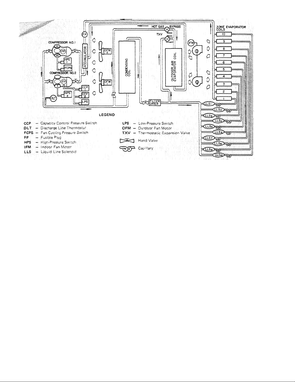
Fig. 1 — Refrigerant Piping Schematic (10-Zone Units Shown, 8- and 12-Zone Units Similar)
partial load operation, difficulties arise in conven
tional hot deck/cold deck units. When some zones
are at full heat, some at partial heat, some at
partial cooling, conventional multizones must
operate the hot and cold decks simultaneously at
high energy cost. The Carrier Modular design
satisfies each zone’s demand by a discrete
module(s). There are no hot decks, cold decks or
zone air mixing dampers to waste energy. The only
energy expended is that required to heat or cool
the individual zone. Since there is no mixing,
energy is saved and operating costs are significantly
lowered. In addition, the control system provides
excellent humidity and temperature control. Multi
stage cooling is available on larger zones where 2 or
more modules are used for efficient control of
zone space requirements.
The following features and safety devices are
provided on the refrigerant cycle:
1. Suction line accumulator
2. Crankcase heaters
3. High- and low-pressure switches
4. Discharge line thermostat
5. Time Guard® circuit
6. Airflow switch for indoor fan motor
7. Internal motor protection thermostats em
bedded in compressor motor windings
8. Hot gas bypass capability
9. Compressor unloading capability
10. Filter-driers
PSYCHROMETRICS ^ The 48MA/50ME units
differ psychrometrically from the conventional
multizones due to the operation of the outdoor air
coil. The coil in the Carrier units cools and
dehumidifies the outdoor air entering the unit thus
assuring that raw outdoor air is not passed along to
the zones. This air treatment by the outdoor air
coil (and also by the zone module evaporator coils)
provides excellent low load performance and
precise temperature control to the conditioned
space. The only large load variation occurs on the
outdoor air coil where a thermal expansion valve is
used. This allows the use of simple capillary tube
expansion devices on the zone coils. The zone coils
cool and dehumidify a mixture of return air and
outdoor air — outdoor air at the approximate dew
point temperature of the return air.
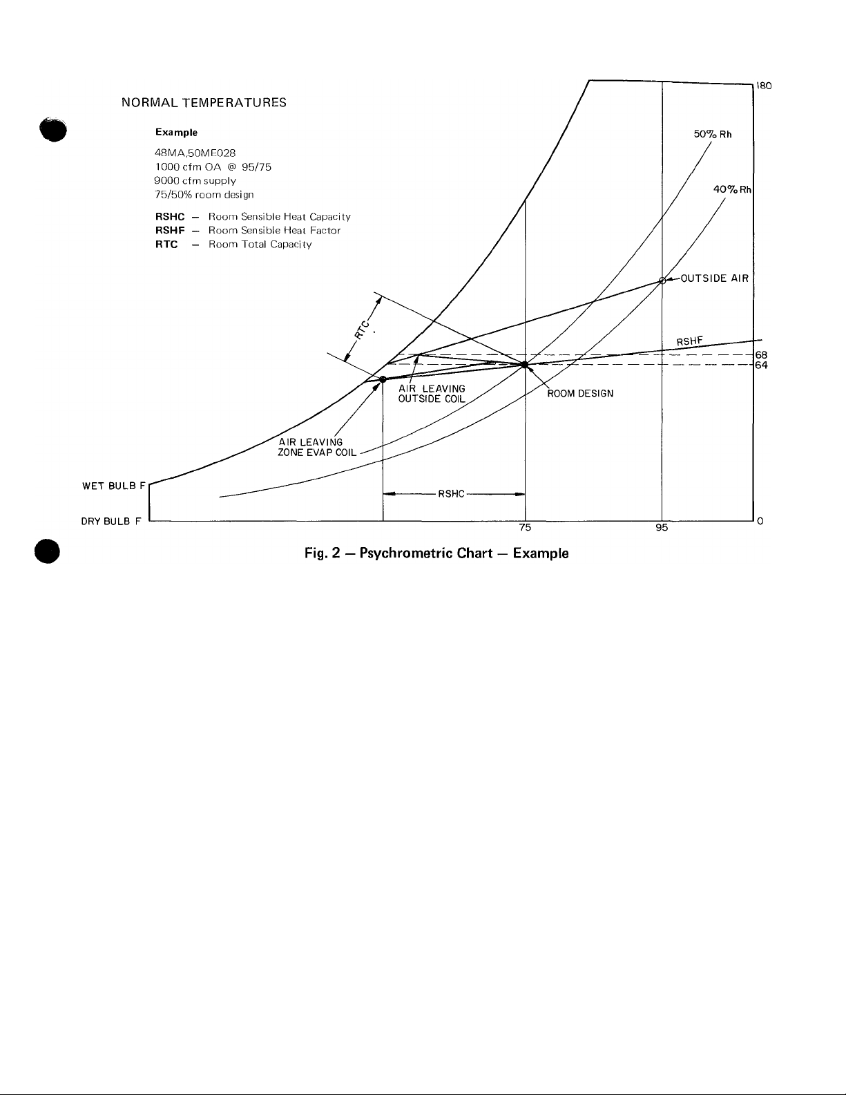
The psychrometric chart (Figure 2) illustrates
this air treatment for a typical set of conditions. As
an example: 1000 cfm of outdoor air at 95 F/75 F
having 99 grains moisture content enters the
outdoor air coil and is cooled and treated so that
the air leaving the coil has 68 grains of moisture
content. The outdoor air coil under these con
ditions has a capacity of 60,000 Btuh of which
39,000 Btuh is sensible. This is a coil sensible heat
factor of 0.65. By examining the room conditions,
it is evident that the outdoor air coil is very
effective in removing the latent load. At 75 F/50%,
the room content is 64 grains of moisture. The
percent moisture removed with respect to room
conditions is:
Page 5
GRAINS OF MOISTURE/
LBS OF DRY AIR
% removed
99 - 68
99 - 64
100 =
88.5%
The 1000 cfm of outdoor air at 68 grains is mixed
with 8000 cfm of return air at 75 F/50% room
conditions (64 grains). This mixture then enters
the zone modules and is cooled and dehumidified
by the zone coil.
Heating (General) — The 48MA/50ME modular
multizone units offer a wide range of factoryinstalled heating options.
In all cases, the modular design provides a
number of small heating steps to maintain very
close discharge temperature control without wide
variation. Conventional multizones cycle a few
large increments to maintain the necessary hot
deck temperatures and, thus, cannot control dis
charge temperature as well as the modular units.
Another feature of the modular design is the
reduced impact of heater malfunction. Any unit
can have a malfunction — such as an open coil in a
relay or contactor or gas valve failure in a gas-fired
unit. The Carrier 48MA/50ME units, with 8, 10 or
12 independent heating sections, would experience
heat failure in one module only and all others
would operate normally. Conventional multizones
could lose a large percentage of heating capacity or
the entire heat source in the hot deck could
become inactive.
The Carrier modular multizone units are de
signed to provide reliability, serviceability, oper
ating economy and comfort control — features
difficult to match with conventional hot deck/cold
deck reheat multizone units.
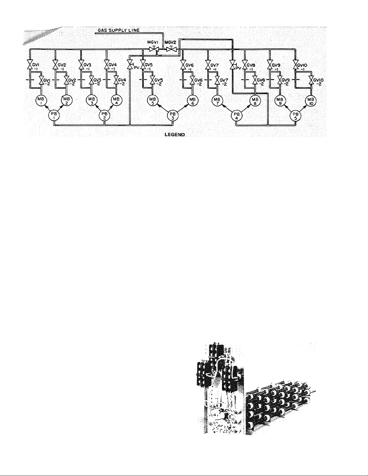
GAS HEATING SYSTEM (48MA) Each module
has a 2-stage burner, with one pilot per pair of
modules. The first-stage gas valve (115-v) controls
gas flow to the main orifice and to the second-stage
valve. A 24-v solenoid valve provides gas to the
second stage when open (see Eig. 3). Both heating
stages are contained in one valve body.
The gas heating section has standing pilots and
continuous forced draft combustion. The pilots
have automatic spark relight for dependable
ignition.
The 48MA modular multizone has individual 18
ga Chromized steel heat exchangers and stainless
steel main burners in each module.
Safety features on the heating system include:
1. A.G.A. certification of the entire unit design as '
well as the furnace section.
2. Airflow switch for indoor fan motor.
3. Airflow switch for forced draft fan motors.
4. Door switch for combustion compartment.
5. Pilot switch to ensure a pilot flame
Page 6
GV - Gas Vaive (Zone Module)
MOTSS:
t
MS ~ Main Burner
Pirst stage of gas valve is a 115-vott sok-noid; second stage is a
24-voit soienoid with .60% gas bvpess.
Gnits 48MA034 ano 040 fi ave one pilot shotoff valve feeding all
pilot burners.
Unit is eouipped with a forced-draft blower and: the foiiowing
Fig. 3 — Gas Piping Schematic (10-Zone 48MA Unit Shown, 8- and 12-Zone Units Similar)
MGV PS -
Main Gas Vaive
Pilot Sorrier
safety devices: forced-draft airfiow switcfi, tiame rcll-oot pro
tection switch, combustion dtarnbet access door switch, heating
lirrtt switches, and soark-ignitecl automatic pilots. Al! of these
switches are iccateci in the heating section and rrtust. be in safe
condition before tfie inain burners can ignite.
PV ~ Pilot Valve (shutoff;
6. Heating limit switches.
7. Flame rollout protection switch.
In special applications where natural gas supply
is limited, units must be modified to operate under
derated input/output conditions. The 48MA modu
lar multizones can be derated by changing the zone
module burner spuds and gas valve orifices as
follows:
NATURAL GAS FIRED UNITS
TOTAL MODULE
DERATED INPUT (%)
High F ire/Low Fire
90/45
80/40
70/35
SPUD SIZE
No 36
No 38
No 41
No 43
GAS VALVE
ORIFICE SIZE
No 36
No. 38
No. 41
No 43
Under these conditions, the units still have 2 stages
of derated heat input. Derating below these limits
is not approved. If single-stage heat is acceptable,
disconnect high fire stage to permit each module
low fire input only (% as shown under low fire).
Contact Carrier Service Department before de
rating to the above limits.
ELECTRIC HEATING SYSTEM (SOME) - The
SOME electric heating system contains single-phase
Nichrome wire coils (see Fig. 4), wired and phase
balanced to provide 2 or 3 steps of heat control.
Each zone has 2 or 3 steps of strip heat available,
controlled simultaneously by the zone thermostat
and the outdoor air thermostat. When heat is
required, the first stage of zone thermostat ener
gizes the first step of zone heating. The second step
(on 3-step units) of heating is controlled by the
second stage of the zone thermostat. The second
(on 2-stage units) and third step of heating is
controlled by the outside air thermostat (OAT.)
and operates simultaneously with the second stage
of the thermostat (on 3-stage units) when the
outside air temperatures are below OAT. setpoint.
The setpoint on the outside air thermostat is
adjustable from 0 to 55 F.
Safety features include:
1. UL certification on entire unit, as well as
electric heat section
2. Manual reset circuit breakers
3. Klixon high-temperature protection
4. Airflow safety for indoor fan motor
5. Fusible links in each heater phase
6. Two-pole contactors on each element
Fig. 4 — Electric Heating Unit (50ME)
Page 7
нот WATER/GLYCOL HEATING SYSTEM -
Hot water is a frequent selection for heating due to
simplicity of the piping system, the ease in
maintaining uniform temperature control and
quieter operation. In addition, when renovating an
existing building, a hot water heating plant is
usually available.
Carrier’s hot water/glycol heating option
(Fig. 5) is ideally suited for these renovations. Each
zone module has its own high capacity heating coil.
All controls, solenoid operated shutoff valve and
balancing valves are included in the option. There
is no internal piping or wiring; only one connection
is required for supply and return hot water/glycol.
The option does not include internal pressure relief
for partial load operation. External piping to the
unit must be in accordance with existing codes. It
must include proper relief for water flow (the
maximum allowable hot water/glycol system work
ing pressure is 30 psi.) or a modulating control to
compensate for decrease in water flow rate to zone
coils under partial load conditions when some coils
are cycled closed. System heater coils are designed
for operation with a water/glycol solution of 20%
minimum glycol for proper freeze-up protection.
Figure 35 located in the Heating Capacity Section,
page 47 portrays an example of selecting and rating
hot water/glycol heating coils for use with SOME
multizone units.
The hot water/glycol option is not intended for
use on a steam system. Where steam is the only
heating medium available, a steam-to-water con
verter or a steam-to-water interchanger should be
used.
typical multizone design considerations. Using the
Engineering Guide, calculate cooling and heating
load estimates for the areas to be served by the
multizone unit. Divide each area into zones based
on the peak load and control requirements within
the area.
The resulting loads in a typical building have
been calculated as follows:
Cooling
Grand Total Load (GTE) .................... 275,000 Btuh
Sensible Load (SL)
..............................
215,000 Btuh
Room Design....................................75 F db/50% Rh
Outdoor Air (OA) Cfm
.......................................
1000
OA Ambient Temperature .... 95 F db/75 F wb
Electric Power Source
у XT Room Total Load* Room Sensible Load
zone JNo. (RTL)/Zone (RSL)/Zone
1 19,000 Btuh 16,935 Btuh
2 25,000 Btuh 22,505 Btuh
3 25,000 Btuh 22,505 Btuh
4 70,000 Btuh 59,160 Btuh
5 22,000 Btuh 19,720 Btuh
6 25,000 Btuh 22,505 Btuh
7 40,000 Btuh 33,870 Btuh
Total 226,000 Btuh 197,200 Btuh
*Loads are peak loads.
.................................
460/3/60
Heating (Electric Resistance Heat required)
Zone No
1 34,000 Btuh 10.0 kw
2
3
4 111,000 Btuh 32.5 kw
5
6
7
Total*
*Zone Peak Capacities.
Heating Load/Zone
44,000 Btuh 12.9 kw
44,000 Btuh
42,000 Btuh 12.3 kw
44,000 Btuh
81,000 Btuh
400,000 Btuh
Electric Resistance/Zone
12 9kw
12 9kw
23 7 kw
117 2 kw
Fig. 5 — Hot Water/Glycol Heating (50ME)
SYSTEM SELECTION AND OPERATION
To better understand the actual operation of
the modular multizone, a typical design example is
provided.
Refer to Carrier’s Engineering Guide for Multi
zone Unit Systems and contents of this booklet for
Selection:
Due to the many heating options and ranges on
each 48MA/50ME unit, multizone unit selection is
normally based on cooling load requirements.
Enter the 48MA/50ME rating tables in the Per
formance Data Section and select the unit that
meets or exceeds the grand total load at the
specified conditions. (Interpolation may be neces
sary to obtain unit rating at certain conditions;
extrapolations are not advised. Contact Carrier
Engineering for performance data at points beyond
the range of published tables.) The 024 size unit
does not have sufficient capacity to meet load
requirements at any cfm. The 028 size exceeds
load requirements; however, it is the smallest unit
that meets specifications. Thus, the 48MA/“'
50ME028 at: 9000 cfm; 1000 cfm OA; 95 F/75
OA temperature; and 75 F/50% Rh room design
has a TC of 282,000 Btuh, SHC of 219,000 Btuh,
compressor kw of 27.5 and a RSHF of .835.
Calculate the RTC and the RSHC by deducting the
outdoor air load from the unit capacity.
Page 8
The outdoor air load with respect to room condi-
as follows:
outdoor ail
total heat (OATH) = 4 5 (hgg:,- Ьго,ошХ (OA cfm)
= 4.5 (38.61 - 28.29) (1000)
= 46,440 Btuh
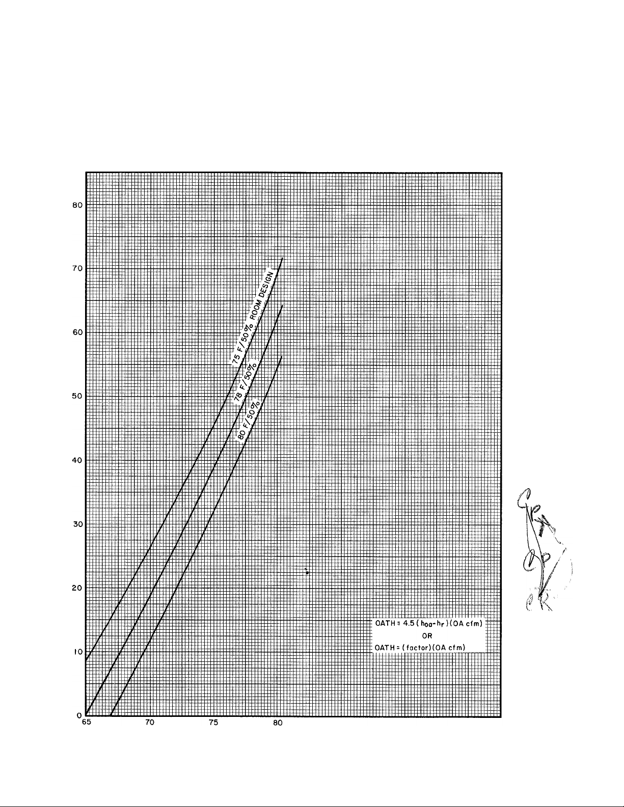
Or, a graph, shown 'in Fig. 6, can be used to find
the OA load factor, 4.5 (hoa “ hfoom). for all
conditions illustrated in the 48MA/50ME rating
tables (Performance Rating Section). Thus,
OATH = (OA load factor) (OA cfm)
= (46.5) (1000)
= 46,500 Btuh
which agrees with the above calculation.
Outdoor air
sensible heat (OASH) = 1.09 (toa ■" boom) (OA cfm)
= 1.09(95 - 75) (1000)
= 21,800 Btuh
<
О
2
u.
0
\
1
z>
H
Ш
Q
<
о
<
I-
o
h-
Ш
a
CO
I-
Э
о
OA WET BULB
Fig. 6 — Outdoor Air Load Selection Chart
8
Page 9

The unit capacity available to offset room loads is.
Room TC = Unit TC — outdoor air TC
= 282,000 -46,500
= 235,500 Btuh
Room SHC = Unit SHC — outdoor air sensible heat
= 219,000 -21,800
= 197,200 Btuh
For comparison:
GTL
SL
RTL
RSL
Load
275.000 Btuh
215.000 Btuh
226.000 Btuh
197,200 Btuh
Unit Capacity
TC = 282,000 Btuh
SHC = 219,000 Btuh
RTC = 235,500 Btuh
RSHC = 197,200 Btuh
The 48MA/50ME size meets or exceeds the
total and zone load requirements at the specified
conditions. The excess RTC decreases space
average relative humidity slightly below the room
design of 50%. By increasing air quantity above
9000 cfm, this excess latent capacity can be
converted to additional sensible capacity if desired.
Since the modular multizone is a constant
volume machine, the selected supply cfm per zone
must be proportioned to satisfy each zone’s peak
load condition.
Room sensible capacities (RSC) are divided
equally among the modules if an equal cfm is going
to each. In this example, the 48MA/50ME028 has
10 modules and the nominal cfm is 900 cfm per
module.
The cfm to each zone can be varied (with
field-supplied manual dampers in zone ducts) to
match different zone requirements, but since the
original rating was based on 9000 cfm supply air,
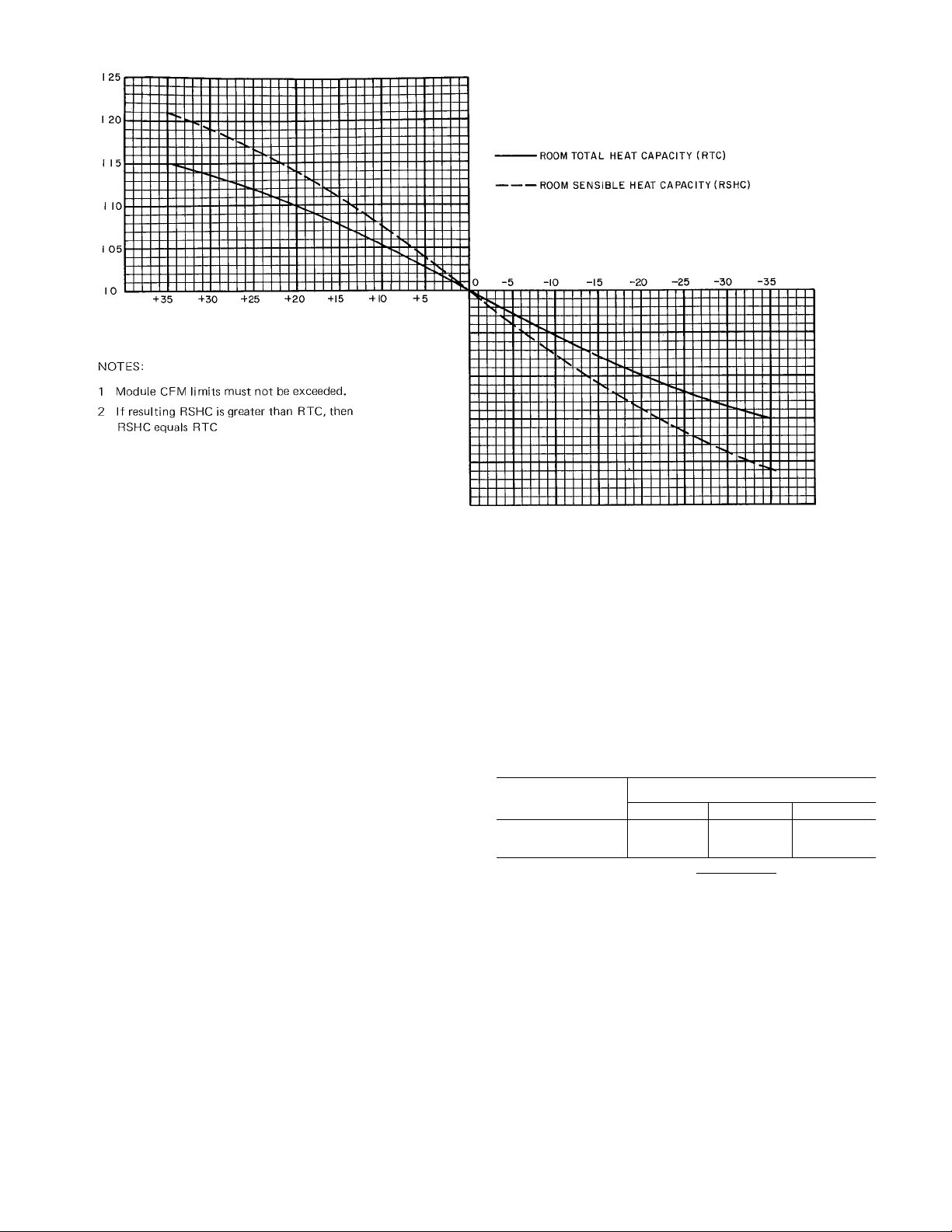
all variations must total 9000 cfm. The effects of
changing cfm quantities on room TC and room
SHC in each module are shown in Fig. 7. When the
cfm is changed (by some percent) from the
nominal in a specific module, then the room
capacity multipliers in Fig. 7 are used to correct
room TC and room SHC. Capacity versus cfm
changes for the example is given in Table 2.
By analyzing each zone’s ratio of deviation
from equal sensible heat allocation, the proper cfm
change is determined. In the example, if building
room SHC is 197,200 Btuh and 10 zones are used,
each zone’s normal room SHC is 19,720 Btuh. But
if zone 3 has 22.505 Btuh room SHC, then by ratio
of 22,505 : 19,720 or 1.14, the cfm change is
+20% (see Fig. 7). Correspondingly, if zone 1 had
16,935 Btuh room SHC, the cfm change is -20%.
In applications where the zone selection is not
an increment of the number of unit modules (i.e.
one zone requiring 500 cfm in a 48MA/50ME028
with 10,000 cfm), refer to Module Cfm Limits,
page 10, for details on using cfm’s below
600 cfm/module.
Formulas required to use ratings are:
Outdoor Air Total Heat (OATH)
OATH = 4.5 (OA cfm) (hoa-hioom)
Outdoor Air Sensible Heat (OASH)
OASH = 1.09 (OA cfm) (toa ~ troom)
Room Total Capacity (RTC)
RTC = Unit TC-OATH
Room Sensible Heat Capacity (RSHC)
RSHC = Unit SHC - OASH
Room Sensible Heat Factor (RSHF)
portp _ RSHC
Leaving Air Temperature (LAT)
LAT = room temperature
RSHC
1.09 cfm
Determine Heating Capacity:
The specified requirement for electric heat
dictates the selection of a 50ME028 unit with a kw
option that meets or exceeds the heating load.
Table 9, page 50 indicates that the 028 unit has
heating capacity options of 66, 88 and 132 kw.
The 132 kw option is selected as it provides
adequate heat for this application. The kw/zone
and number of heat stages available are:
Zone No.
1
2
3
4
5
6
7
Total
Load
10.0 kw
kw 13.2 kw
12.9
12.9 kw
kw
32.5
kw 13 2
12.3
kw 31.2 kw
12.9
23.7 kw 26 4 kw
117.2 kw 132.0 kw 30
Zone Heating
Capacity
13.2
kw
13.2 kw
kw
39.6
kw
Stages
of Heat
3
3
3
9
3
3
6
Stages of heat are controlled individually in the
small zones or collectively in large zones to provide
flexible and continuous control for each zone.
Table 2 — Capacity vs Cfm Changes
ZONE
*Unit total capacity multiplier is obtained from Fig. 7. Use % change from nominal and read multiplier from graph.
RSHC — Room Sensible Heat Capacity RSL — Room Sensible Load RTC — Room Total Capacity
NO. OF
NO.
MODULES
1 1 16,935 16,935/19,720 = 86
2
3 1 22,505
4 3 59,160 59,160/3 X 19,720 = 1.00 0 2700 1 0
5 1
6
7
1 22,505
1 22,505 22,505/19,720 =1.14 +20 1080 1.1
10 197,200 9000
2
RSL/ZONE
PEAK LOAD
19,720 19,720/19,720 =1.00 0
33,870
% DEVIATION
(RSL/NOM UNIT RSHC)
22,505/19,720 =1.14
22,505/19,720 =1.14
33,870/2 x19,720 = .86
% CFM CHANGE
FROM NOMINAL
-20
+20 1080 1 1
+20 1080 1 1
-20 1440 .9
UNIT TOTAL
CFM
CAPACITY
MULTIPLIER*
720
900 1.0
X
9
X
X
X
X
X
X
X
UNIT
NOMINAL
RTC/ZONE
23,550
23,550
23,550
3 X 23,550
23,550
23,550
2 X 23,550
ADJUSTED
UNIT RTC
21,195
25,905
25,905
70,650
23,550
25,905
42,390
235,500
Page 10
LJ
a
z>
2
a:
II
2
O
O
•% CFM CHANGE ■
FROM NOMINAL
I 0
95
90
85
<
a.
<
80
75
Fig. 7 — 48MA/50ME Room Capacity Multipliers
Power Wiring Data — The 50ME028, 460-3-60 unit
with 132 kw of electric resistance heat, has a 75.8
cooling circuit minimum wire ampere and a heating
circuit minimum wire ampere of 207.0. If any
module is operating on mechanical cooling (com
pressor operating), one heating stage in each
module is locked out and cannot be energized.
This, a common feeder can be sized for minimum
wire ampere of 221 (see Fig. 37).
APPLICATION
Diversity — The size, shape and orientation of the
building — as well as the application and location
of zones, influence the degree of diversity that may
be applied to a multizone system.
Since the normal application of multizone units
involves zones where loads are shifting due to solar
energy, people, equipment and lights, diversity will
exist.
The Carrier modular multizones will be affected
by building diversity only on the refrigeration
system. When a particular zone (or zones) thermo
stats are satisfied, a solenoid shuts off the zone
evaporator coil. This enables more refrigerant to
flow to other operating zone coils, creating a larger
capacity for that zone. However, the diversity will
lower the selected unit total capacities.
The 48MA/50ME ratings do not reflect diver
sity but can be converted to diversity ratings by
using the capacity correction factors and formulas
in Table 3.
Table 3 — Capacity Correction Factor (CCF)
LOAD
TC (Unit)
SHC (Unit)
RTC (with diversity)
RSHC (with diversity)
DIVERSITY FACTOR
1.0
1 0
1 0
90 .80
97
94
[TC (CCF) - OATH]
(Diversity Factor)
[SHC (CCF) - OASH]
Diversity Factor
94
89
This is accomplished by rating the unit assum
ing that no more than 9 of 10 zones would be on
at one time, 90% diversity. The same logic applies
to other diversity factors on an average basis, such
as 85 or 95%.
A rating with a diversity factor results in a
lower room SHF; therefore, a reselection at a
higher total unit cfm is advisable to take full
advantage of the building diversity.
Limitations
MODULE CFM LIMITS AND FAN PER
FORMANCE — The cfm limits per zone are
1200 cfm maximum and 600 cfm minimum. The
10
Page 11

outboard zones in the 8-, 10- and 12-module units
are limited to a maximum of 1000 cfm. The
maximum limit is necessary to prevent blow-off to
the heat exchangers and into the ductwork. The
minimum limit prevents burner cycling on limit
switches and prevents electric heater cycling. At
reduced cfm’s, zone evaporator coils overfeed
refrigerant, but there is no liquid flood-back to the
compressor as it is protected by a suction line
accumulator.
For applications below 600 cfm, it is recom
mended that the heating controls be modified as
follows:
Gas fired (300 to 599 cfm) — Use first-stage
heat only, deactivate second stage.
Electric Resistance (450 to 599 cfm) — Use
first- and second-stage heat on 3-stage units.
Electric Resistance (300 to 449 cfm) — Use
first-stage heat on 2- or 3-stage heat units.
Optimum performance is delivered in the 800 to
1000 cfm range. Extremely low cfm requirements
reduce unit cooling capacity. Low zone cfm
applications may also be handled by sizing the
zone for a higher cfm (to increase unit efficiency)
and diverting the extra air into the return air
system or a larger interior space. Extra air should
not be diverted into spaces with different
perimeter wall orientations.
Fan performance data. Table 4 and Fig. 32, 33
and 34, (Fan Curves) are located in the Fan
Performance Section and are based on 15% out
door air. When the outdoor air dampers are closed
and there is no outdoor ventilation air into the
unit, unit cfm is reduced by 2 to 6%. This
reduction is due to the static pressure drops
existing in the separate airflows thru the unit. This
reduction should be considered in special applica
tions where little or no ventilation is required and
cfm requirements are critically designed.
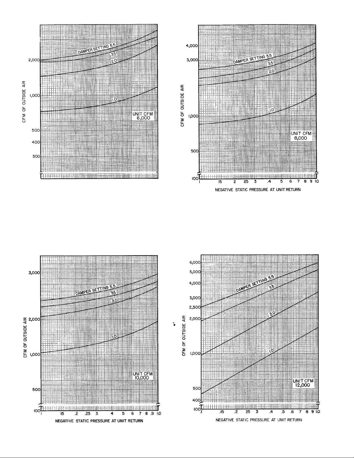
MAXIMUM VENTILATION LIMITS Under
normal mechanical cooling, the amount of ventila
tion air that can be introduced is a function of the
outdoor air damper setting and negative static
pressure at the return air intake of the unit. Figures
8 thru 11 show ventilation air versus negative static
pressure at various settings of the outdoor air
damper. A 5.5 setting of the ventilation control
dial is the maximum opening of the dampers. The
ventilation dial can be set in any position from 0 to
5.5 to obtain the desired cfm of outdoor air. The
ventilation dial is located on the control panel
adjacent to the heating section.
Reheat Applications — A space with a high latent
load and a very low sensible load may require
reheat capability for dehumidification. Typical
spaces of this type are conference rooms or visual
aids rooms where people congregate with the lights
out.
Reheat control is achieved on the 48MA/50ME
unit by wiring a humidistat (Fig. 12) in parallel
with the cooling thermostat on any zone requiring
reheat capability. This may be done on one module
or all modules. When using reheat control on
electric resistance heat units, extreme care must be
exercised with power wiring as heating and cooling
can operate simultaneously in each module.
When the zone’s humidity level reaches the
setpoint of the humidistat, mechanical refrigera
tion is activated for that zone module and the air is
dehumidified and then reheated on thermostat
demand before being discharged to the zoned
space.
The 48MA/50ME Economizer — The 48MA/50ME
units can be equipped with an economizer control.
The control functions as follows: with ambient
temperatures above the economizer changeover
point, the outdoor air damper is set at the
ventilation position, cooling is accomplished by the
compressors when the room thermostat calls for
cooling. If the zone is not calling for cooling, the
mixed air is circulated thru the space. When the
ambient temperature drops below the economizer
changeover point, the compressors are locked out
and the damper motor is under control of a mixed
air thermostat to maintain a mixed air temperature
low enough to provide cooling when the room
thermostat demands it. (See Fig. 13.)
11
Page 12
3,000
100
I 15 2 25 3 .4 5 .6 7 8 9 10
NEGATIVE STATIC PRESSURE AT UNIT RETURN
Fig. 8 — Ventilation Air Chart,
48MA/50ME016
Fig. 9 — Ventilation Air Chart,
48MA/50ME024
Fig. 10 — Ventilation Air Chart,
48MA/50ME028,030
Fig. 11 — Ventilation Air Chart,
48MA/50ME034,040
12
Page 13
If a zone thermostat calls for cooling while in
economizer mode, a set of cooling relay (CR)
contacts close, energizing the economizer relay
(ECR). See Fig. 14. The ECR is a DPDT plug-in
relay. For economizer damper control, the ECR
locks out the outside air damper adjustable poten
tiometer and shifts the damper control to a Mixed
Air Thermostat (MAT.). The MAT. sensor, located
in the fan section, adjusts the outside air damper to
maintain a preset mixed air temperature (see
Fig. 15).
The 48MA/50ME economizer operation pro
vides economic use of outdoor air for low-cost
cooling. When all zone cooling thermostats are
satisfied, economizer controls are bypassed and the
outdoor dampers are modulated to the minimum
ventilation position. The mixed air temperature
increases, minimizing the amount of reheat re
quired in other zones that require heating.
Refer to Economizer Economics, page 15 to
determine if the addition of an economizer is
justified.
Г
HA — Heat Anticipator S)
Hu - H umidistat
TC — Thermostat, Cooling
TH — Thermostat, Heating
-------------------
----------------------
~l LI
LEGEND
-------
Fig. 12 — Humidistat Connections
Screw Terminal
Printed Circuit
Factory Control Wires
Field Wiring
SEQUENCE;
1 — Ambient temperature decreases
2 — Compressor is locked out by economizer control thermostat
3 — Outside air damper is regulated by mixed air thermostat
to maintain fixed mixed air temperature
Fig. 13 — Economizer Operation
C — Compressor Contactor
CCP — Capacity Control Pressurestat
CHR — Crankcase Heater Relay
CR — Cooling Relay
DLT — Discharge Line Thermostat
ECR — Economizer Relay
ECT — Economizer Thermostat
EXC — Exhaust Motor Contactor
EXR — Exhaust Relay
FCPS — Ean Cycling Pressurestat
HPS — High Pressure Switch
HR — Holding Relay
IT — Internal Thermostat
LPS — Low-Pressure Switch
MCR — Master Cooling Relay
MHR — Master Heating Relay
OFC — Outdoor Fan Contactor
TM - Ti mer Motor
LEGEND
Fig. 14 — Economizer Condensing Schematic
13
Page 14
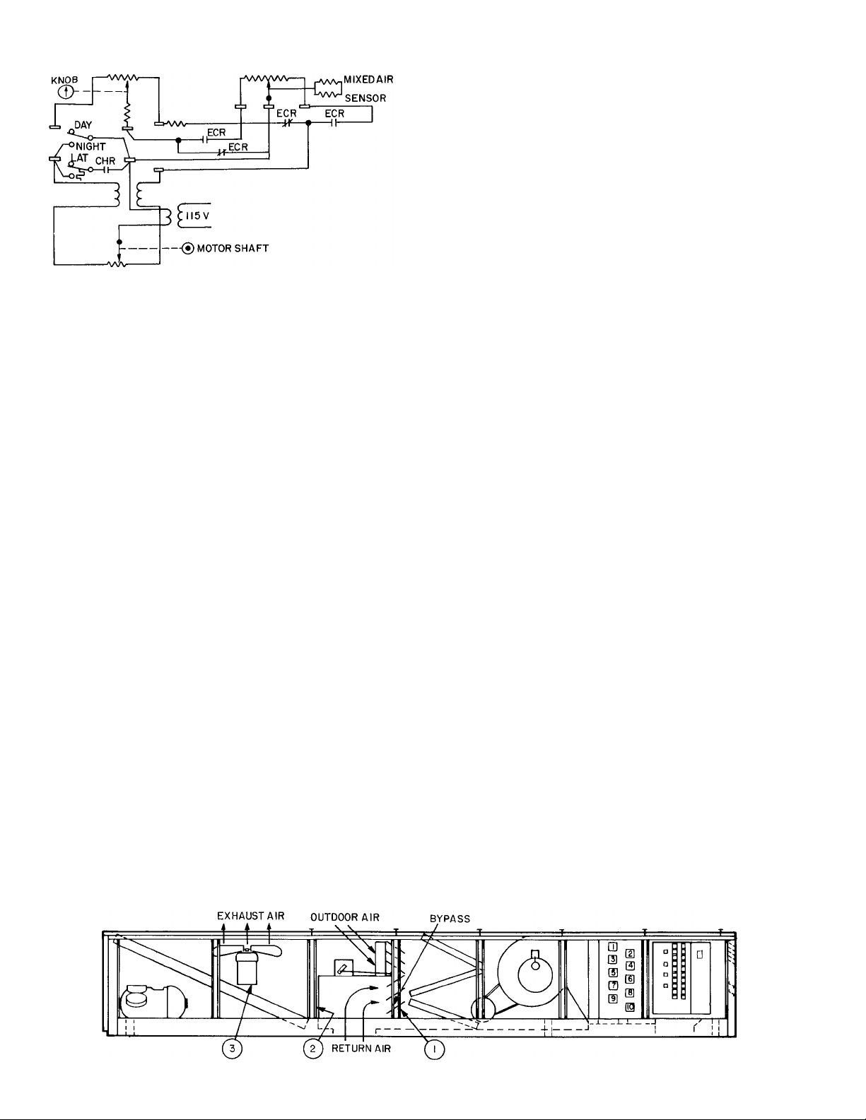
OA damper adjust
MOTOR POT
CHR — Crankcase Heater Relay
ECR — Economizer Relay
LAT — Low Ambient Thermostat
OA — Outside Air
Fig. 15 — Economizer Damper Control Schematic
Economizer And Exhaust Performance — An
MIXED AIR THERMOSTAT
LEGEND
economizer can be readily factory installed on the
48MA/50ME since the damper motor and outdoor
air damper are standard equipment. The econo
mizer package consists of a return air damper,
linkage, plug-in relays, MAT. wiring, and mixed air
thermostat.
When the 48MA/50ME unit is on full econo
mizer control, the supply cfm to the space drops
off slightly since the resistance of the outdoor air
intake is generally greater than that of the return
air ductwork. To partially offset this, the return air
dampers have a built-in bypass.
With the outdoor air dampers fully open and
the return air dampers fully closed, the total cfm
drops 15%. The total cfm consists of 70% outdoor
air and 30% return air thru the built-in bypass. If,
for example, the unit normally operates at
10,000 cfm supply air, the minimum supply cfm
when the economizer is operational is 8500. This
8500 cfm consists of 6000 cfm outdoor air and
2500 cfm return air. As the ambient temperature
drops from 48 F (recommended economizer setpoint), the proportion of outdoor air to the supply
air required to maintain mixed air temperature is
less, the outdoor air damper begins to close, and
return air damper begins to open (see Fig. 13). As
this happens, total supply cfm progressively
increases from 8500 cfm to 10,000 cfm (design).
An exhaust damper option is also available for
use with the economizer. It is located between the
return air plenum and the condenser fans. The
option consists of a TPDT plug-in relay (EXR), an
exhaust damper, and a plug-in jumper. The damper
provides a forced exhaust of indoor air during the
economizer operation. The exhaust damper opens
when the return air damper is 25% closed. With the
damper installed, ECR and EXR are energized
simultaneously. The EXR locks out outdoor fan
motor (OFM) controls (32LT on OFMl and FCPS
on OFM2 and OFM3) and outdoor (condensing)
fan motors operate at full speed, discharging excess
return air to the atmosphere thru the open exhaust
damper (see Fig. 16).
The 48MA/50ME exhaust operation is similar
in performance to a relief damper except that the
exhaust dampers are mechanically linked to the
return air dampers and the condenser fans operate
to produce a pressure differential which aids the
exhaust cycle. At approximately 0 in. wg at the
return air opening, the 48MA/50ME units exhaust
between 150 to 200 cfm/ton. With positive return
static, more air is exhausted. At -0.40 in. wg
(.25 in. wg on the 016 unit) return air static,
exhaust capabilities of the units drop to zero.
In the example, the 4000 cfm exhausted at
0 in. return static accounts for all but 1100 cfm
outdoor air introduced by the economizer outside
air section. In practice, this excess cfm is con
sidered a nominal ventilation rate, slightly pres
surizing a building to eliminate drafts and
unwanted air seepage. This excess air filters out of
the building thru doors and window spaces. The
^slight positive pressurization of the building aids
the exhaust fans in removing air. If, however, the
balance between the building static and exhaust
system leaves the building with unacceptably high
positive static pressures, a relief ventilator or roof
power exhauster may be used. For extensive or
SEQUENCE:
1 — Return damper closes 25%.
2 — The exhaust damper opens
3 — The OFM (condensing fans) speed controls are bypassed and
fans run full speed, exhausting return air to atmosphere
Fig. 16 — Exhaust Damper Operation
14
Page 15
m
complicated return air duct systems with static
pressure greater than -0.2 in. wg at the return air
plenum, duct mounted return air exhaust fans can
be installed for proper airflow. However, return air
exhaust fans add to the operating cost and increase
noise level. More efficient duct design methods
should be investigated to eliminate the need for
special return air exhaust fans.
Economizer Economics — Economizer control on a
multizone unit does not necessarily reduce
operating cost as it would on a single zone unit. A
single zone unit either heats or cools; a multizone
unit can do both simultaneously. Therefore, in a
multizone, the economizer operates to maintain a
mixed air temperature low enough to cool a zone
with a high internal load. The remaining zones
requiring less cooling or heating must have heat
added to offset cooling capacity available but not
needed. This is true of any multizone with any
type of control system.
The amount of heat required to neutralize the
overcooling capacity is dependent on:
1. The percent cooling capacity required from the
unit, and
2. The mixed air temperature required to satisfy
the zone with the highest internal load.
As the ambient temperature drops, the percent
of outdoor air needed to maintain a mixed air
temperature is less. Since the reheat or wasted heat
added is a function of the difference between
outdoor air introduced and ventilation rate,
operating cost is reduced at lower ambients. A high
ventilation rate also reduces the reheat requirement
and associated cost. The following example illus
trates the need for a careful analysis of job
requirements before arbitrarily selecting on econo
mizer control.
Example:
A 48MA/50ME unit is operating with econo
mizer control and supplying 10,000 cfm of 55 F
mixed air. The normal ventilation rate is 2000 cfm.
Assuming a realistic cooling load of 50%, 5000 cfm
of the 55 F air is used for cooling. Since the
ventilation rate is 2000 cfm, half is sent to the
cooling zones leaving 4000 cfm of low-cost cool
ing. The remaining 5000 cfm of 55 F air, including
1000 cfm of ventilation air, is going to zones with
either no load or a heating load and must be
neutralized.
Although 4000 cfm or low-cost cooling is ob
tained, an extra 4000 cfm of air must be heated to
some degree above and beyond that in a unit
without economizer controls.
For an identical unit without economizer con
trol, only 4000 cfm of the 5000 cfm needed for
cooling requires mechanical cooling, since the
1000 cfm of ventilation air is already cooled. Of
the other 5000 cfm, 4000 cfm is return air and is
neutral, and 1000 cfm is ventilation air to be
heated. In the final analysis, it must be determined
if it is more economical to heat 4000 cfm from
55 F to 75 F, or to cool it from 75 F to 55 F. The
answer depends on the efficiency of the cooling
and heating source.
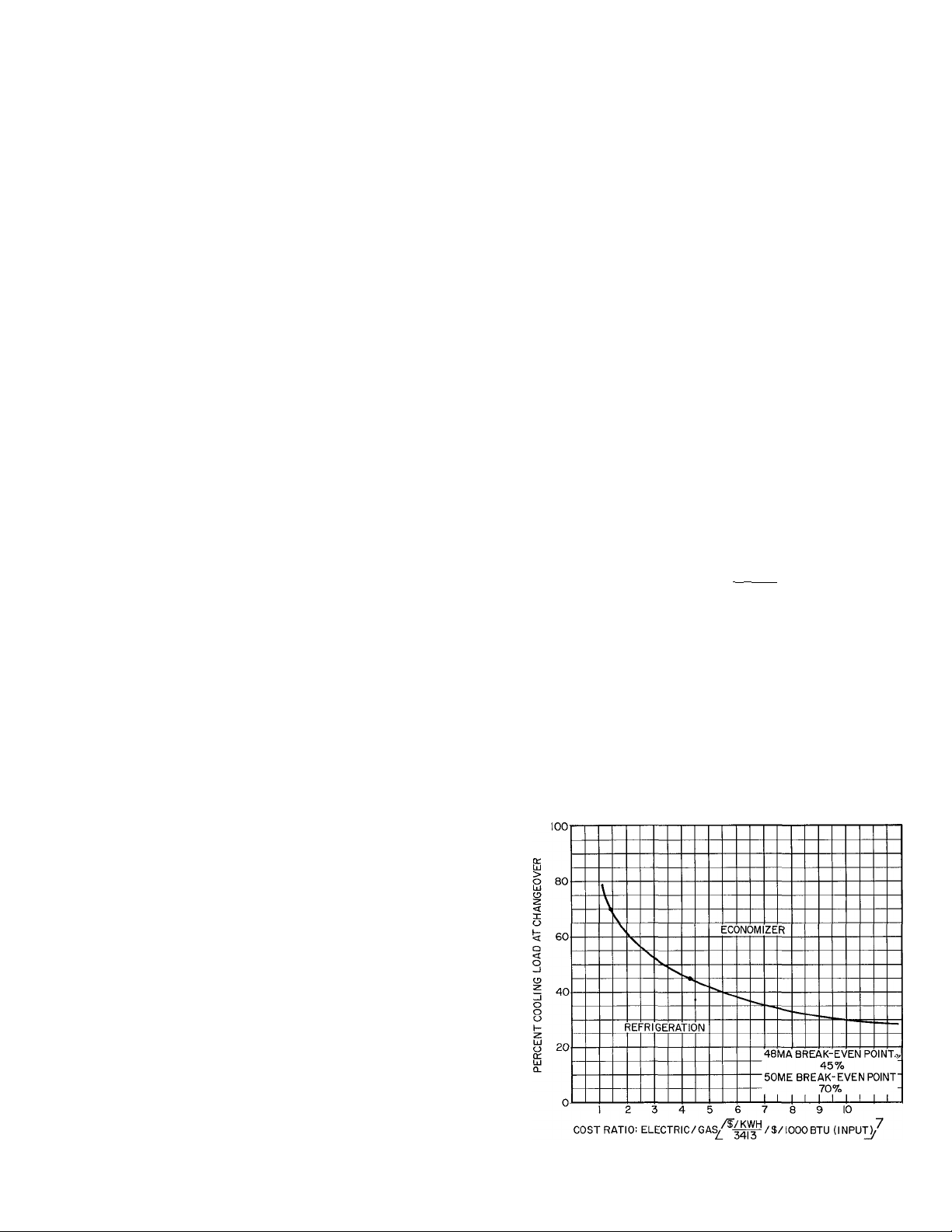
An example of economizer economics is illus
trated in Fig. 17. The graph plots percent cooling
load versus relative energy cost (electricity to gas)
and is based on the following typical assumptions:
48MA028 — 10,000 cfm, 15% outdoor air
48 F outdoor changeover temperature
75 F room design
55 F supply air temperature
Compressor changeover point (COP.)
of 3.3 (100 F condensing temperature
and unloaded compressor were used
to obtain this value)
The relative cost figures are in $/Btu input for
gas and $/kwh electric cost converted to Btu.
Example:
$.10/100,000 Btu (input) - gas cost
$.015/kwh - electric cost
Convert electric cost-
$.015/kwh X kwh/3413 Btu x |q5qqq
= $.44/100,000 Btu
Cost Ratio:
$.44/100,000 Btu _ , ,
.10/100,000 Btu
Therefore, if cooling load is less than 45%
(from graph) at the changeover temperature, the
economizer is uneconomical for 48MA units.
For 50ME electric heat units, the cooling load
break-even point is 70%; the internal load must be
greater than 70% to justify economizer control.
Fig. 17 — 48MA/50ME Economizer
Break-Even Point
15
Page 16
The cooling load for this comparison is the
internal load (lights and people) minus the negative
transmission at the changeover temperature (48 F).
To determine the percent cooling load, compare
this value to the unit design cooling capacity.
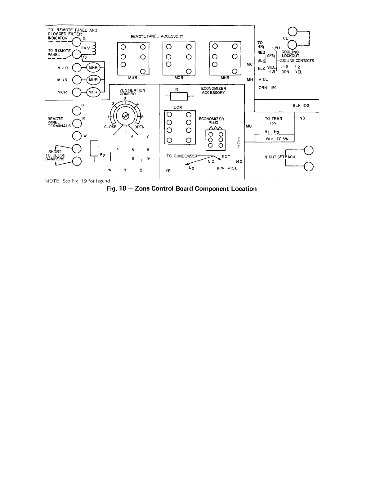
Night Setback — Niglit setback control can be
added to a 48MA/50ME unit using field-supplied
components. There are 3 sets of terminals on the
accessory section of the unit zone control board
(see Fig. 18). The terminals are used in combina
tion to achieve the system desired. Terminal sets
are: cooling lockout (CL), night setback (NS) and
“Short To Close Dampers.” Red jumpers are
factory wired across CL and NS; “Short To Close
Dampers” are bare (see Fig. 19). If the circuit
between CL terminals is broken, 115-v power to
the compressor control circuit liquid line solenoids
and economizer thermostat (if used) is shut off. If
the circuit between NS terminals is broken, 115-v
power to the zone control transformers is shut off.
By replacing both jumpers with appropriate
switches and connecting proper switch across
“Short To Close Dampers,” NS control is attained.
Although many versions of NS are possible, the 3
most common methods are detailed here.
METHOD NO. 1 - HEATING NIGHT SETBACK,
COOLING LOCKED OUT, AND CONTINUOUS
INDOOR EAN OPERATION
This automatic NS system requires a Honeywell
S659A seven-day timer, a Honeywell R8227B fan
center (night setback relay) and a Honeywell
T822D thermostat (heating type) 24-v service. In
this system (see Eig. 20), when the timer reaches
the “Night” position, the switches are as shown.
CL opens, dampers close and NS opens. The fan
continues to operate.
As the temperature falls, the NS thermostat
located in the average temperature space energizes
the NS relay (fan center) which in turn energizes
the zone control transformers. The individual
zones then heat until the NS thermostat is satis
fied. The dampers remain closed and cooling is still
locked out. If a day/niglrt switch is used, the NS
thermostat is overridden and heating is controlled
by the normal thermostats.
Accessory remote panel assembly and/or ac
cessory economizer may be used with this system
if desired. Cycling indoor fans with NS thermostat
is possible if the accessory remote panel is not
used. Connect the field wiring to the MU terminals
instead of the NS and the indoor fan contactor will
cycle with the heaters. Although this system does
not provide a time off delay for the fans after
heater shutdown, test experience indicates that this
is not a problem on these units.
METHOD NO. 2 - HEATING NIGHT SETBACK,
COOLING LOCKED OUT AND CYCLING IN
DOOR EANS
This system requires a Carrier remote control panel
assembly 48MA900041, Honeywell S659A sevenday timer, Honeywell R8227B fan center (night
setback relay) and a Honeywell T822C thermostat
(cooling type).
The number of candidate systems for NS
increases with the use of the remote accessory
panel. A typical system is shown in Eig. 21. The
use of the master unit relay (MUR) and the master
cooling relay (MCR) requires 24-v wiring only.
Installing the timer and the NS relay in proximity
to the remote control panel results in all wiring
being located inside the building in one area.
16
Page 17

LEGEND
1
AB — Accessory Board
AFS - AirfI ow Switch
APS — Air Pressure Switch
C — Compressor Contactor
Cap. — Capacitor
CB — Circuit Breaker
CCB — Compressor Circuit Breaker
CCP — Capacity Control Pressurestat
CH — Crankcase Heater
CHR — Crankcase Heater Relay
CL — Switch, Cooling Lockout
CO — Convenience Outlet
Compr — Compressor
CR — Cooling Relay
DLT — Discharge Line Thermostat
ECR — Economizer Relay
ECT — Economizer Thermostat
EXR — Exhaust Relay
FCB — Fan Circuit Breaker
FCPS — Fan Cycling Pressurestat
FL — Fusible Link
FRS — Filter Media Runout Switch
Fu — Fuse
GV - Gas Valve
Gnd — Ground
HA — Heat Anticipator
HC — Heater Contactor
— High Pressure Switch
HPS
— Holding Relay
HR
— Heater
Htr
— Ignitor
I
— Indoor Fan Contactor
IFC
— Indoor Fan Circuit Breaker
I FCB
— Indoor Fan Motor
IFM
— Internal Protector
IP
— Low Ambient Thermostat
LAT
— Liquid Line Solenoid
LLS
— Low-Pressure Switch
LPS
— Limit Switch
LS
MCR
— Master Cooling Relay
(MC)
MHR
— Master Heating Relay
(MH)
MUR
— Master Unit Relay
(MU)
— Normally Closed
IM.C.
— Normally Open
N.O.
— Night Setback Switch
NS
— Outdoor Air Thermostat
OAT.
— Outdoor Fan Contactor
OFC
— Outdoor Fan Circuit Breaker
OFCB
— Outdoor Fan Motor
OFM
— Plug
Pig
— Resistor
R
RB
Sw
TB
TC
TH
TM
T ran
ZB
' o
□□ s
□
o
A
Relay Board
Switch
Terminal Block
Thermostat, Cooling
Thermostat, Heating
Timer Motor
Transformer
Zone Board
Receptacle
<
Plug
Terminal Block
Terminal (marked)
Terminal (unmarked)
Circuit Board Terminal
Splice
Terminal, Circuit Board,
Factory Connected
Terminal, Circuit Board,
Field or Accessory
Factory Wiring
Accessory or Field Wiring
Circuit Board Run
To indicate common potential only, not to
indicate wire.
Page 18

C2-2
OFCI
L2 ZB
L2 *B
-----------
1
——lF=------------------- --- ---
1
1
1
1
----------——|F=
1
---------------II
aSlL---- -------------9 41^ 7
3C*S»i
aSUi
-----------------
-------------------------
^CRI,
-----------------
LLS7
LLS6
LLS9
LLS4
LLS3
LLS*
LLSI
Fig. 19 — Unit As Shipped From The Factory
TO ZONE CONTBOL
SCHEMATIC
Ills zb (• zone only)
Page 19

In this system, the MUR is energized by the NS
controls. This opens a set of normally closed
contacts and shuts down the unit, including indoor
fans. The outdoor air dampers are also closed by
the MUR. Cooling lockout is attained by energizing
the MCR. Energizing these relays turns the unit off
and the NS system seems to work in reverse.
A cooling thermostat is used on heating NS.
When temperature rises, the thermostat, in series
with the night switch, energizes the NS relay. Its
contacts close and, in series with the time clock
contacts, energize the MUR. As the space tempera
ture lowers to the NS setting, the NS thermostat
de-energizes the NS relay which de-energizes the
MUR, turning on the unit.
Again the day/night switch overrides the NS
clock and heating can occur because the NS relay is
de-energized. The factory jumpers remain across
CL and NS terminals.
note: 24V WIRING
BETWEEN CONTROLS
*CONNECT HERE INSTEAD OF NS
TO CYCLE INDOOR FANS
CL — Cooling Lockout
MUR — Master Unit Relay
NS — Night Setback
Fig. 20 — Night Setback, Method #1
SWITCHES SHOWN IN NIGHT POSITION,
rT? m n? m
I A I 1A| I A I I A|
DAY/NIGHT SWITCH
II5V
FIELD
SOURCE
LEGEND
APS — Air Pressure Switch
FRS — Filter Media Runout
Switch
MCR — Master Cooling Relay
MHR — Master Heating Relay
MUR — Master Unit Relay
c=iOR(^ Terminal (Circuit Board,
Field or Accessory Conn )
-------------
Accessory or Field Wiring
-------------- Factory Wiring
------
-------
Circuit Board Run
NIGHT SETBACK
THERMOSTAT (COOLING TYPE)
, I
--------
T~1
i cb
HI H2
REMOVE JUMPERS BETWEEN
NC AND R: C AND W
Fig. 21 — Night Setback, Method #2
ACCESSORY BOARD
ON BASE UNIT
Page 20

This system opens the dampers when the
indoor fans start. To keep them closed, short
across the W-R terminals on the remote control
panel or the “Short To Close Dampers” terminals
during the NS period.
METHOD NO. 3 -- USING ACCESSORY RE
MOTE PANEL, HEATING AND COOLING
NIGHT SETBACK AND INDOOR FAN CYCLING
This system requires a:
Carrier remote control panel assembly
48MA900041
Carrier heating and cooling thermostat
HH07AT074
Carrier subbase HH93AZ070
Night setback relay (Honeywell fan center
R8227A)
Seven-day timer (Honeywell S659A)
The system (Fig. 22) is a proposed heating and
cooling niglrt setback with fan cycling. The
thermostat is a standard Carrier part with no
switches on the subbase. This requires a NS relay
with normally closed contacts so an alternate,
Honeywell R8227A is required.
Because cooling is not locked out, the clock
switches that close at niglit are used to directly
close the outdoor air dampers by connecting across
R and W on the remote panel accessory. Again the
MUR shuts down the unit (including the indoor
fans). When the NS thermostats reach their set
tings, the NS relay is energized, opening the NC
contacts and de-energizing the MUR.
However, if a “wild” zone exists, it is allowed
to cool on heating NS or vice versa. This may be an
advantage on some applications between zones.
Again when the day/night is switched to
“Day,” the NS is overridden and the unit operates
normally except the dampers remain closed at
night.
SWITCHES SHOWN IN NIGHT POSITION,
LEGEND
APS — Air Pressure Switch
FRS — Filter Media Runout
MCR — Master Cooling Relay
MHR — Master Heating Relay
MUR — Mastei Unit Relay
TC — Thermostat, Cooling
TH — Thermostat, Heating
c=.OR® Terminal (Circuit Board,
_______
________
Switch
Field or Accessory Conn )
Accessory or Field Wiring
Factory Wiring
' Circuit Board Run
NIGHT SETBACK
RELAY
FILTER
V 'T "V
<3F-ri-]-i-g
NOTE: 24V WIRING
BETWEEN CONTROLS
XI
. .¿XI c 3x2
TO REMOTE PANEL
MHR .
=*=o4
MUR I MUR I
-0==j=O=I
MCR |_MCRj I
O) SHORT TO HI H2
^ CLOSE DAMPERS
l2j lI_i
0
REMOVE JUMPERS
BETWEEN NC ANDR; CANDW
Fig. 22 — Night Setback, Method #3
18
ACCESSORY BOARD
ON BASE UNIT
#
Page 21

Again, 2 jumper wires have to be removed from
the back of the remote panel to isolate the
day/night switch.
MORNING START-UP — To conserve energy and
lower total operating costs, the outdoor dampers
may be closed when starting the system in the
morning. During a warm-up period, when the
system is operated for one or two hours before
occupancy, only building return air should be
heated. The extra load of cold outdoor air intro
duced uses extra heat energy. Ventilation is
unnecessary until space is occupied, so the air
introduced produces unnecessary heat waste.
The same principle holds true on a cooling day,
when outside air transmits heat and moisture to
the evaporator coil. This extra load above the
return air only load is an unnecessary expense.
This can be offset by wiring a heating or
cooling thermostat across the “Short To Close
Dampers” terminals on the zone control board.
The thermostat senses return air temperature and
the outdoor air damper does not open until the
building is at the required temperature.
A time clock can also be used and set as
follows:
1. Occupied cycle: 8 a.m. to 6 p.m. Outdoor air
damper is open and the system is controlled by
individual zone thermostats.
2. Night setback cycle: 6 p.m. to 6 a.m. Individual
zone thermostats are on night setback (NS)
cycle. The outdoor air damper is closed, the
unit is reset down and controlled by NS
thermostat.
3. Warm-up (or cool-down) cycle: 6 a.m. to 8 a.m.
Outside air damper is closed by time clock and
the system is controlled by indoor zone
thermostats.
Using any method, increased economy is
achieved and building requirements are satisfied.
MISCELLANEOUS
Sound and Vibration — All roof mounted air
conditioning equipment produces sound and vibra
tion. On light types of roof construction, sound
and vibration may be transmitted directly to the
occupied space. Accordingly, sound attenuation
and vibration isolation are important design con
siderations on any rooftop application.
Sound attenuation can be accomplished in
many ways depending on the specific design
construction of the building. Roof mounted units
can be located over unoccupied space (i.e. storage
areas, utility rooms, corridors) where slightly
higher sound levels are not objectionable. Supply
and return duct systems can be acoustically lined
to prevent sound transmission into occupied space.
If open plenum return air systems are used, an
acoustical trap or fiberglass-lined chamber can be
used to attenuate the sound. Simple return duct
elbows and tees with 5-ft minimum fiberglass lined
legs and low static pressure drop should be
considered when using open plenum return air
systems. Figure 23 illustrates a procedure for
forming an acoustical trap using the roof curb area
under a 48MA unit.
NOTES:
1 Dimension A is approximately 7 in for optimum performance
2 Acoustical lining is 1-in 1-lb density, neoprene-coated fiberglass
3 Return air grille should be located at least 15 ft from return air opening
Fig. 23 — Acoustical Trap Installation
19
Page 22

Roof mounted air conditioning equipment
usually has adequate vibration isolation of internal
components. However, light roof construction or
equipment location displaced from main roof
supports may dictate additional isolation to elimi
nate vibration.
Special vibration isolating bases and curbs
designed for rooftop applications are available
from some vibration isolator manufacturers. This
equipment virtually eliminates vibration trans
mission on critical applications. However, care
should be exercised when selecting this equipment
for use with a multizone. The design and installa
tion of vibration rails on a Carrier 48MA/50ME
should ensure that the interfacing of the vibration
isolator and the curb maintain watertight integrity.
Thermostat Usage and Control
USAGE - The thermostats used with the 48MA/
SOME units are either a 2-step heat/l-step cool or
2-step heat/2-step cool. A single module can have
only one step of cooling, but can have 2 steps of
heating. When 2 or more modules are grouped
together, the 2-step heat/2-step cool thermostat
can be used. Modules are grouped together by the
installation of factory-supplied jumpers on the unit
zone control board.
The thermostats are automatic changeover with
a 3 F dead spot between heating and cooling.
There is a 1°F differential between the first and
second steps of heating or cooling. Two subbases
are available for use with the thermostats; one with
off-heat-auto.-cool switch and one without
switches for tamper-proof installation. The tamper
proof subbase has provisions for locking the
thermostat cover and temperature selectors.
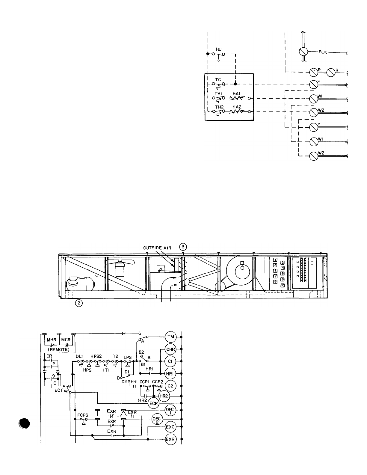
CONTROL - The thermostat field wiring connec
tions are made at the screw-type terminals on the
printed circuit board near the heating end of the
unit. This is commonly called the zone control
board. (See Fig. 24.)
Each module has the following thermostat
terminals: R (24-v power supply), Y (for cooling),
W1 (first step heating) and W2 (second step
heating). Pairs of modules are combined to form
nests: 1 and 2; 3 and 4; 5 and 6; etc. Each nest
forms National Electrical Code (NEC) Class II
circuit powered by its own 40 va transformer. Each
transformer is basically limited in capacity to
operate only the relays within its nest. Therefore,
contacts are provided in the relays to transfer the
signal to another module in an adjacent nest.
By correctly installing jumpers on zone control
board terminals, the contacts from a relay in one
nest power a relay in the adjacent nest using the
transformer of the adjacent nest. This technique is
known as multiplexing.
Same Nest Ganging - Figure 25 shows 2 modules
(1 and 2) of the same nest ganged together to form
a 2-module zone. Field jumpers are installed on
same lettered terminals to energize both control
relays simultaneously for cooling or first- and ^
second-stage heating relays or gas valves for
heating.
Figure 26 is similar to Fig. 25 except a 2-step
cooling thermostat independently powers the Y
connections for 2-step cooling in one zone. These 2
examples have not left the particular nest, so no
multiplexing has been done.
Adjacent Nest Ganging — Figure 27 shows 2
modules (2 and 3) of adjacent nests ganged
together in one zone so multiplexing is in effect.
Module 1 is in a zone of its own. When CR2 is
energized by the cooling thermostat, terminal 6 is
powered thru CR2 contacts 1 and 3 by the
transformer of the second nest. Then terminal 6 is
jumpered to 1 and CR3 is energized. Thus, on a
call for cooling, modules 2 and 3 are energized
simultaneously. The same principles and pro
cedures are followed for the first and second steps
of heating.
Multiple Ganging — Figures 28 thru 31 are further
examples of ganging and multiplexing zones to
provide 2, 3 or 4 modules per zone. These typical
examples demonstrate the principles of multi
plexing. The same procedures are followed for the ^
remainder of the zones on the unit. Many more ^
combinations are possible. Do not overload a
transformer by powering more than one relay of a
different nest in additon to the relays in its own
nest.
Multiplexing is done from top to bottom of the
zone control board . . . from module 2 to 3 and 4,
from 4 to 5 and 6, and from 6 to 7 and 8. The
contacts of one module are powered by the nest of
the next higher numbered module (see Fig. 24).
Return Air Systems
If the ceiling plenum on a top floor is used as a
return air plenum, the return air is heated from the
time it leaves the room and enters the unit. This is
due to roof load or if heat from lighting is added to
the plenum.
When considering the top floor, the roof load
does not raise the return air temperature signifi
cantly and, therefore, its effect is considered
negligible when selecting a unit.
Return air light troffers, however, can add
considerable heat to the return air. Using a
48MA/50ME unit with a return air light troffer
system can impose various design problems since
the purpose of the system is to reduce the supply A
cfm to the space by reducing the space load. With ^
the 48MA/50ME this may result in a very low
20
Page 23

supply cfm — much lower than the unit was
designed for. If the supply cfm is raised to satisfy
the unit, the purpose of the return air light troffers
is defeated. As a general rule, a return air tempera
ture rise of 5 to 10 F does not cause a problem,
and special ratings can be made available.
In addition, when the supply cfm is reduced, as
above, the outdoor air quantity remains constant.
This results in a higher than normal percentage of
outdoor air which the 48MA/50ME unit may not
be capable of introducing. For return air light
troffer systems, exercise care when using the light
manufacturers’ data concerning the amount of heat
actually returned to the unit because with the
higher return air temperature, a portion of the heat
is transmitted back to the space thru the ceiling.
21
Page 24

fR Q-Q MODULE I NEAR SIDE
r O
0
0 o
0
HR2-I
0 0 0
0 0 o
HR3-I
,. CR3
, GV5
0
0 0
0
HR4-I
O 0 o
0 o o
HR5-I
0
O 0
0
HR«-I
wi O—a
[Y
X
'"CW
Y O-io
w*0^
o o o
0 o 0
HR 7-1
o
O 0
o -2
HR8-I
O O 0
0 o O
HCI
HC2
HCZ
HC3
HC3
HC4
HC4
HC5
HC9
HC6
HC6
HC8
-2
•2
-2
-2
-1
•2
*■
0 0 o
0 o o
HR2-2
0 0 o
o o
o o 0
HR3-2
0 0 0
0 O 0
HR4-2
0 0 o
0 o
0 O 0
HR5-2
O O 0
o o o
HR6-2
0 0 0
o o
O o 0
HR7-2
0 O 0
o o o
HR8-2
0 O 0
O 0
0 0 0
CR!
0 o o
o o
0 o o
D O O
O O
0 o o
CR2
CR3
o o o
o o
o o o
0 o o
o o
0 o o
CR4
CRB
0 0 0
o o
o o o
0 o o
o o
o o o
CR6
CRT
o o o
o o
o o o
o o o
o o
0 o o
CR8
«(>o
Y
E L 3„„,
, ,CR?^
,(>^
■ a
'O
lo
0
0
0 o 0
0 O 0
0
0
0 0 o
3 0 0
HR99M
0 0
HRI0,i2-l
HR9.1M
0 0
HRI0.I2-I
HC9
HCII
-1
HC9
HCM
-2
HCIO
HCI2
HCIO
HCI2
HC9
HCII
-1
HC9
HCII
-2
*•
HCIO
-2
IIUU
HR9. I|.2
0 0 o
0 0 0
HRIO,t2-2
0 0 o
0 o
0 o o
HR9,11-2
0 0 0
0 0 0
HR 10.12-2
0 0 0
0 o
0 0 o
HC9
H^ll
LLS9
LLSII
tU'i
Hao
HCI2
-3
CRIO.IS
HC9 CR9.M
HCllI——
|o O o
O O
(boo
O o o
tH,a
O O
HOO
0 0 0
HCI2
ClflO.IZ '
L2
NOTE: See Fig 19 for legend
Fig. 24 — Zone Control Board
22
Page 25

ANTICIPATOR
SETTINGS
LEGEND
CR — Control Relay
GV — Gas Valve
HA — Heat Anticipator
HR — Heating Relay
TC — Thermostat, Cooling
TH — Thermostat, Heating
Tran ~ Transformer
Q) Screw Terminal
I
----
1 Quick-Connect Terminal
-----------
Factory Control Wires
rrr-- ; Printed Circuit
.
---------
Field Wiring
Fig. 25 — Two-Stage Heat, One-State Cool — Same Nest
23
Page 26

LEGEND
CR — Control Relay
GV — Gas Valve
HA — Heat Anticipator
HR — Heating Relay
TC — Thermostat, Cooling
TH — Thermostat, Heating
Tran — Transformer
0 Screw Terminal
Quick-Connect Terminal
Factory Control Wires
Printed Circuit
Field Wiring
Fig. 26 - Two-Stage Heat, Two-Stage Cool - Same IMest
24
Page 27

#
LEGEND
CR — Control Relay
GV — Gas Valve
HA — Heat Anticipator
HR — Heating Relay
TC — Thermostat, Cooling
TH — Thermostat, Heating
Tran — Transformer
0 Screw Terminal
1
----------
1 Quick-Connect Terminal
--------------
Factory Control Wires
-------
— Printed Circuit
---------
Field Wiring
Fig. 27 - Two-Stage Heat, One-Stage Cool - Adjacent IMest
25
Page 28

LEGEND
CR — Control Rela^
GV — Gas Valve
HA — Heat Anticipator
HR — Heating Relay
TC — Thermostat, Cooling
TH — Thermostat, Heating
Tran — Transformer
Screw Terminal
0
Quick-Connect Terminal
Factory Control Wires
Printed Circuit
_______
Field Wiring
Fig. 28 - Two-Stage Heat, One-Stage Cool - 3 Modules Per Zone
26
Page 29

LEGEND
CR — Control Relay
GV “ Gas Valve
HA — Heat Anticipator
HR — Heating Relay
TC — Thermostat, Cooling
TH — Thermostat, Heating
Tran — Transformer
0 Screw Terminal
Quick-Connect Terminal
Factory Control Wires
Printed Circuit
---------
Field Wiring
Fig. 29 — Two-Stage Heat, One-Stage Cool — 4 Modules Per Zone
27
Page 30

LEGEND
CR — Control Relay
GV — Gas Valve
HA — Heat Anticipator
HR — Heating Relay
TC — Thermostat, Cooling
TH — Thermostat, Heating
Tran — Transformer
0 Screw Terminal
Quick-Connect Terminal
—- Factory Control Wiies
Printed Circuit
— Field Wiring
Fig. 30 — Two-Stage Heat, Two-Stage Cool — 4 Modules Per Zone
28
i
Page 31

ANTICIPATOR
SETTINGS
HAI
.13
HA2
.57
NOTE:
COOLING
Stage 1 — Module 3
Stage 2 — Module 2 & 4
If thermostat wires are interchanged,
the reverse may be obtained
HEATING
Stage 1 — First Stage of Modules 2,3 & 4
Stage 2 — Second Stage of Modules 2,3 & 4
LEGEND
CR - Control Relay
GV -
HA -
HR TC - Thermostat, Cooling
TH Tran —
Gas Valve
Heat Anticipator
Heating Relay
Thermostat, Heating
T ransformer
Screw Terminal
0
Quick-Connect Terminal
czn
Factory Control Wires
Printed Circuit
_____
Field Wiring
Fig. 31 — Two-Stage Heat, Two-Stage Cool — 3 Modules Per Zone
29
Page 32

PERFORMANCE DATA
Room Design 75 F/50% Rh
COOLING CAPACITIES
48MA/50ME016
OUTDOOR
AlP
TEMP
Db
Wb TC SHC
65 168 118
8 j
70
65 164 116 15 4 169 129 15 7
70 164
73 164 116
75
65 160
70 160
95 75 160
78 160
80
70 156 112 16 5
100 75
78 156 112 16 : 171 120
70 152
105
75 152 110 17 0 164 125
no 78
115 75
OUTDOOR
TEMP
Wb
Db
65
85
70
65
70 200 141 18 8 212 151
73
75
65
70
95
75
78
80
70
100
75
78
'70
105
75
no 78
115 75
0
K w
14 8 174 l26 Is i
168 118
164
160
156 112
14 8
116 15 4 173
15 4
1 16 15 4
114
16 0 165 131
114
16 0 169 126 16 4
114 16 0 173 121
114 16 0
114
16 0
16 5
no 17 C 160 130
109 is 5! 161 124 18 5 171
148
144 107
TC SHC
20.1
204
200 141 18 8 208 155 19 ; 212
200 1 11
200
196
1 96 140 19 5 207 153 20 2
196 140
196 1 10 19 5
196 140 19 5 216 143
T9T 137
19?
192
[187 135
187 135 20 9
178
18 C
0 750 1500
K w
143 18 0 212 153 18 5
143 18 C 217
18 8
141
18 8
19 5
140^
19 5
2Q r-
137
20 2 207 150 21 2
137 20 2 209 147 21 4 221
20 9
iTT 21 6
fsT
22 3
TOTAL UNIT CFM
4,000
Outdoor A r Cfm
750
TC SHC
178
176 121 16 0 183 125
177 119 16 i 186 121
175 118
177 1 16 16 0
164
168
155
Outdoor A
TC SHC
215 148
216 146 19 7 227 148 20 3 210 159 19 3 225 164 20 2
203
212 148 20 5 222
214
202 155
197 157'
201 152 21 9 211
199 150 22 8
i9T 155 23 3
K w
122 15.3
124
15 9
16 2 168
16 6 182 127 17 1 167 126 16 3 178 133
16 8
17 C 170 143 17 3
128
17 2 177 133 17 7
123
17 4 181 127 18 0
17 5 165
17 8 172
Too 18 8 162
5,6o6
r Cfm
K w
149
18 ■
19 5 219
19 6
157 19 9 208 l73 20 2
145 20 6
20 8 230 144
20 ijH
no" ToT 176
1500
K w TC SHC
SHC
TC
134
177
184 124
172 140
179 131
174 137 16 7 167 126 16 3 175
186
189
TC SHC
216 161
224
224
214 164
227
20T
216
15 2
15 6 176
15.8 171
16 2 171 128 15 8 179
16 4
16 5 171
146 16 4 167 126 fl6 3 172
17 4 167 126 16 3 180 130 17 1 190 133 17 6 172 138
121
17 5 167
116
149 17 9 158
139
18 3 158
139 19 ■
19 •;
152
K w TC SHC Kw
18 7 215 161 18 6 222 171 19 0 226 179 19 2 222 178 19 0 229 188
19 ■ 215
152
167 19 4
19 9 210
158
152 20 1
20 6 206 157 20 1 216 171 20 7 222 182 21 1
154
21 1
148 21 4
21 6
ITCT 21 3 20 r
160 21 8
154
22 1
22 i
166
22 6
210 166 23 6
'178' 240
6
Kw
130
176
171 128 15 8 182 133 16 3
163
163 124 16 9 173 136
163 124
154
140 1 19 18 4 159 142 19 1
210
210
206
206 157 20 1
206 157 20 1
206 157 20 1 224 160 21 2 236 162 21 9 212
201 155 20 8
201 155 20 8 217 164 21 9 227 172 22 5
196
196 153 21 5 209 169 22 4 217 184
191 151 22 2 206
186 149 22 9 198 173 23 8 206"
15 2 181 139 15 4 184' 146 15 6 181
130
15.2
15 S 176 141 16 0 179 152 16 2 176 140
128
15 8
128
126 16 3
124 16 9
16 0
123 17 4
17 4
123
121 17 9
0
161
18 6 226 167 19 2 233 170 19 5 222 178 19 0
159
19 3 218 173
159
19 3 221 169
159
19 3
1 57 20 1 213 i'75 '20 5 217
20 8 i
T55"
TsF '21 5 20T 174 22 2
5,000
Dutdoor A r Cfm
750
TC SHC
184
134 15.6
16 2
136
183 131
182
170
175 132 17 6
165 143
168 138 18 1 175 152 18 5
166 137 18 7 - - - 158
TOTAL UNIT CFM
)utdoor Air Cfm
TC SHC
223
220
222
2rr
214
16 4 191
16 6 r74l
143
16 8
138
16 9
128 17,2 - - -
141 17 3
17 5 181
17 9
6,500
750
19 8
20 0
166
20 1 231
166
21 0
163 21 1
J7T 21 5' T88
21 / 223 178 22 2
168
23 3
168
1500 0
TC SHC
Kw
190
185 143
188
180
186 139 17 4 172 138
175
- -
170
Kw
TC SHC
222 185 20 0 217
227 176 20 3 217
234
229 172 21 5 212
233
2^2
215
Kw
15.9
137
16 4 176 140
137 16 6
16 8 176 140
133
16 7 172 n38
'■"158"
149 17 0 172 138
155 17 6 167
146 17 9 167
162
18 2
1500
Kw
170 20 6 217
166 20 7 217
.....
20 8 212
166 21 7 212
U., g..
iW InT' 202
23 0 202
184 24 0
24 4 191
195
6,000
Outdoor Air Cfm
750 1500
SHC Kw
TC
142 15 4'^
142 15.4 189
181
176
140
172 138
M36 17 2
136 17 2
167 136
134 17 7 169
162
134 17 7 172 149 18 3
162
132 18 2
130 18 7
153
-
6 750 isoo'
TC SHC
17'6 19 7
176 19 7 227 185 20 3 233 193 20 6
176 19 7 229 182 20 4 237 187 20 8
176 19 7 231 181 20 5 239 183 21 0
174 20 5 219
174
212
174
174 20 5 228
174 20 5 229 177 21 5
207 172 21 2
207 172 21 2
207 172 21 2 222 181
169
169
197 167 22 6
165 23 3
TC SHC
h§6
150 15 7 188
146
16 0 181 152 16 3 183 164 16 4
16 0 184
16 0 186 145 16 5 192 149 16 8
16 0 187 143 16 6 194
16 6 176 155
16 6 179 150 17 0 183
16 6
16 6 184 142
16 6 185 140
17 2
Kw TC SHC
20 5 222
20 5
21 9 nn T9T 22T ziT 210
21 9
148
182 145
174
152 17 5 178
177 147 17 7
179 144 17 8
154
169
148
153 19 3
162
8,000
Outdoor Air Cfm
232 183 19 5 239 187 19 9
224 190 20 1
...
187
225 182 21 3 233 189
179
'216 189 '21'8 222 204 22 2
220 184 22 0 227 195 22 5
214
186 22 8
210 185 23 6 - 202 189
Kw
TC
SHC Kw
158 15 8
194 149 16.1
15.8
16 4
16.8
17 1
17 2
17 3
18 1
18 9
155 16 6
189
145
178 170 17 0
161 17 2
189 151 17 5
_
-
- - -
167
- -
- -
H73 173 18 4
„
-
- - -
- - -
48MA/50ME024
Kw
TC SHC
19 4 233 196 19 6
202 20 4
228
20 9 223 207 21 2
21 1 227
21 4
22 2
24 1
199
21 4
21 8
- -
- - -
- - -
22 9''
221 201 23 3
- -
16 9
17 8
Kw
*
-
_
„
-
OUTDOOR
AIR
TEMP
Db
Wb
65 265 190 24: 275 203 24 6 280 213
85
70
65 259 188
70
90
73
75
65 254
70
95 75 254 185
78 254
80 254
70
100 75
78
70
105
75 242 180
no
IT
115 75
Kw — Compressor Motor Power Input
SHC — Sensible Heat Capacity (1000 Btuh)
TC - Total Capacity (1000 Btuh)
SHC
TC
265 190
259 188
259
259
254
248
248
248
242 180
zT
T77
230
1 . , —
0
K W
24 0
24 9 269 206 25 5 273 221 25 7 271 210 25 6 280 229'”’ 26 i 284 244 26 3
24 9 274
24 9
188
24 5 279
188
185 25 8
185 25 8
25 8
185 25 8
185 25 8
182 26 7
182 26 :
182 26.7 269
27 6 254
27 6 259
W4
174
29 2
/ (Mil
Outdoor Air Ctm Outdoor Air Ctm
1000 2000
TC SHC
197 24 8 289 201 25 3 277 213 24 6 291
280
200 25 8
277 196 25 9 287 201 26 5
193
262
208
267 202 26 7 275
273 196 27 0
276 192 27 2 290 196 28 0
279 189 27
261 205
266
198
194
207
201
T?9
256"
246 206 30 4
___ -
K W
TC SHC
282 209
26 ' 291
267 229 26 6
26 4
284 204 27 7
294
127 0
268
27 9 277 212 28 6 258
283
28 1
261
28 ■;
28 8 270
29 9'
268
256 236 31 2
--
K w
24 ? 277
26 2 271
196 26 7 271
217 27 -
190 28 3
225 28 0 258
203 29.0 258
237
28 9
220 29 5 252 202 28 3 267
219 30 8 W: 199'
L,— 1 __ L. . — . . 1
TOTAL UNIT CFM
9.000 11.000
0
TC SHC
271
264^
264
264
264
264
252 202 28 3 263
239 197
K W
24 6
213
210 25 6
25 6 287
210
210 25 6 289 216 26 6 299 219
26 5
208
26 5
208
26 5
208
26 5 285 214 27 7 297 219 28 4 272
208
26 5 287
208
27 4
205
205 27 4
205 27 4
29 1
29 n253 229 31 C
NOTES: 1. No values are given where unit cannot maintain the assumed room
1000 2000 0
TC sttc K w
287 226
284
273 231
277
282 219 27 5 292
270 ’
275
277 217
263” 222 3CT
25 2
220
25 -
223 26 3
219 26 5 296 225 27 0
27 6 277
27 3 284
225
27 8
212
228 28 2 276 248 28 6 265
221 28 5 284 235 29 1 265
28 6
29 0 269 255 29 5
230
224
29 3
design relative humidity since the moisture content of the air leaving
the unit is higher than the assumed room moisture content
2 Ratings are gross and do not include fan motor heat deduction.
30
....
TC SHC
291 236
224 25 8 285 234 25 1 298 242 25 8 305
298
291 232
252 27 2 272
240
227
- - -
- - - 265 226
243 30 0 258 223
276
-
258 31 7 245 218
262
Kw
TC SHC
25 4 285
26 7
27 2
27 7 272 229
28 1 272
234
232
278
278 232
232
278
232 26 0 295 238
278
229
229 26 9 288 240
229 26 9 291
229 26 9 292 233 28 2
272
226
226 27 8 280 243 28 8
223 28 7
258
251 221
48MA/50ME028
. .
-
Outdoor Air
1000
Kw TC SHC
294 248 25 6 298 258 25 8
25 1
26 0 287 250 26 5 291 266 26 7
26 0 291
26 0
26 9
26 9 284 247 27 7
27 8
27 8
28 7
29 6 268'
30 3
244 26 7
241
293
280 252
236
276' 249
239
283
269 252
273 245 29 7
243 30 8
258 250
_ - -
Cfm
Kw
26 9 302 246
27 0
27 4
27 9
28 1
28 6
29 0
29 5 274
31 4
2000
TC SHC
297
304 241
283 273
290
- - -
- - -
282
- -
- - -
- -
- - -
246 26.1
254 27 1
'262 28 0
- -
260
274 29 8
- -
- -
K w
27 3
27 5
27 6
28 9
t
L
Page 33

PERFORMANCE DATA
Room Design 78 F/50% Rh
COOLING CAPACITIES
48MA/50ME016
OUTDOOR
AIR
TEMP
Db
85
90
95
100
105
no
115
AIR
TEMP
Db
Wb
85
90
95
100
105
.1.10
115
Sipop
0
TC
SHC
183
1 32
J83
Ш
131
178
131
178
131
178
178
13]
129
174
129
174
129
174
129
174
229
274
127
169
127
169
]6?
1?7
125
165
2 25
165
223
160
121
156
0 750 1500
TC SHC
220 158 18 9
220 158
216 156
216 156
156 19 7 228 163 20 4 235
216
216 156 19.7 230
154 20 4 217
21 •
154
21 1
154 20 4
211
154
211
154
211
206 152
152 21 2
206
206 152
150 21 9
201
201 150
148 22.6
196
191 146 23 .3 202
Outdoor Air^Cfm
750
Kw
15 5
15,5
16 1
16 1
16 1
16J
16 7
16 7
16 7
16 7
16.7
17 3
17 3
-17,3
17 8
1J.8
2 8,4_
18 9
Kw TC SHC
18.9
19 7
19 7 226 165 20 2
20 4
20 4
20.4 229 157 21.5
21 2 215
21.2
21.9
SHC
T£
186
141
]36,
L90
182
143
185
138
137
136
134
188
177
145
180
140
183
136
186
133
187
130
143
175
178
138
135,
J81
145
170
240
]73
139,
l'70
164
144
6,000 7,500
Outdoor Air Cfm Outdoor A
227 167 19 2 230 175
163 19.4 236
231
169 20 0 225
222
161 20.5 238 163
171
220 167 21 0
224 163 21 2 232
160 21 4
227
169
164 22 0
219
161 22 2 231
221
171
210
1 66 22.7
213
210 165 23.6
170 24 1 210 192 24 ^ 197
TOTAL UN IT CFM
. *7.',6,000”
Outdoor Air Cfm
IIPP.
Kw
,15
15 7
188
-!5,?,
l?i]
16 3
183
16 5
189
16 6
193
16.6
195
179
16 9
17 0
184
17 2
190
17 4
1 94
1_96
VIA
1~79
’l7 6
17 8
185
188
IL?.
174
18 2
179
18.4,
i,78
19.1
169
19 5
Kw
TC SHC
231 172 20 5 223 174 20 1
220 187 21 0 218 172 20 9 224
20 8
226
237
240 159 22.2 218 1 72 20.9
220
21 7
227
22 5 215
221 181 23.2 208 16^ 22,4 219 184 23 1
219
Kw
11?,
15 8
148
1 6,1
13?.
154
16 4
16 7
145
16 9
139
.17,0
1.35
17 0
160
17 3
151
141
17 6
17 7
135
17.8
J31,
1.57
17 8
18 2
148
.LM
Л11
163
18 4
154,
1§,8
1,54
1*9.5
166 19 9
К w
19 4
167 19.7
181 20 t 223 174
167
20 8 233
20.9
21 3
178
169
21 7 218 172 20 9
163 22 0 218 172 20 9 233 177 21 8
184
22 1 213 170 21 6 220
22 5 213 170 21 6
175
169 22 8 2^3 170
190
22 9 208
181 24.2 203 '65 23,'
P
TC
SHC
Kw
144
188
'.44
L§8
183
143
183
143
183
143
183
1.43
141
178
141
178
141
178
141
178
141
178
174
139
174
139
139
174
169
137
169
137
164,
1Ж
159
133
0
TC SHC
176 19 3
228
228 176 19.3
174
174
223
218 172 20 9 227 185 21 4
167
163
.TC,
157
15.-8
16 4
16 4
16 4
¡.?И
17 0
17 0
1 / 0
17 0
17.,0
17 5
17 5
!7,5
18 I
18.1
1,8,6
19*2
TOTAL UNIT CFM
К w
235 185
238 181
20 1 229 187
233 183
20 1 2.35 180 20 7
20.1 236
231
735 175
225
227 179 22 5
21 6
22 4
216 188
216 183
23 8 207 187
192
19,4
187
189
191
193,
182
184
187
189
l?i
179
182
18 !.
174
177
174
161
TC
75p
S.H.C
"1 б’о
153
J6.J.
148
155
150
1 48
146
157
152
148
145
2,42
155
150
147
157
152
152
15Г
r Cfm
750
SHC
19 6
'9.8
20 4
20 6 238
20.8
178
189 21 2
180 21 6
21.9
187 22 2
182 22 4
22 9
24,0
24 1
Jllw
16 5
16 7
16 8
16.9
17 1
17 3
17 4
17 6
172
17 9
18 0
18J.
18 4
18,6
19.3,
197”
К w TC SHC
SH_C
T_c
19~з'
198
188
193
196
]98
183
188
193
183
188
177
182
238
243
233
241 185 'H 1
244 181 21.2
228
232
238
242
244 176 22 1
227 202 22 5
232 193
236
22,
226
223 198
214 209 25 ■
1500
Kw
Тб 0
16.3,
1.51
16 6
166
157
16 9
17 0
151
^^.2
148
17 2
172
17 5
163
154
17 8
169
18 1
18 3
160
175
18 6
18.9
166
1500
К w
193 19 8
184 20,1
199
20 6
190 20 9
20 1 21 4
196 21 7
187 22 0
181 22 3
22 8
187 23 1
207 23 3
198 23 6
94.6.
TC
SHC
292
T56
,156,
192
154
187
187
154
154
187
187
154
182 152
182 152
182
152
182
152
182
152
17*7
150
177
150
,177
2,50,
172
148
172
148
]46
iV/
144
162
IC
£HC
334
192
234
192
229
190
190
229
190
229
190
229
188
223
188
223
188
223
188
223
188
223
186
218
186
218
186
218
184
213
21 3
18.£
207
J82,i
202
180
P
0
Outdoor Air
Kw
16 0
16.,0
16 6
16 6
16 6
16,6
17 1
17 1
17 1
17 1
,17 1
17 7
17 7
1,7^7
18 3
18П
18.8
19 4
Outdoor Air Cfm
Kw
J,C„
__
TTo
19,6
20 4
20 4
20 4
20 1
££2
21 2
21 2
21 2
21 .£
21'V
21 9
21 9
22 /
22 7_
23.
24 1
IC
195'
]98
190
193
194
196
185
188
190
192
193
18*2
185
Ш7,
177
170
17“
169
243
234
238
240
241
230
232
235
237
239
226
229
231
221
223
.2] 9^
21 1
7,000
Cfm
750
l£w
SHC
'l64'
16 T
160
16.3 Л02
16 7
166
162
16 9
159
16 9
17£
J5?
17 3
168
164
17 5
17 6
159
156
17 7
n 8
2 5£
'160'
18 0
161
18 2
2843
..IJi
168
18 6
163
18.8
*162
19'?
168
48MA/50ME024
9,000
***750
..........
Kw
SHC
202
198
20-1
204
20 7
200
20 9
197
21 0
21.1
195
£ 5
206
301
21 7
197
21 9
194
22 0
192
22 1
2*03
22 5
199
22 7
196
22 8
20.~
2ТЗ 2
2.3 1
201
199,
24.3
204
24 8
TC
197
192
196
199
201
186
191
195
185
180
TC
_4_.
248
238
242
246
24£
233
236
242
231
236
226
229
1500
SHC
171
163
177
169
163
1,59
184
175
165
181
180
jjpo
SHC
'210
201
21 5
207
202
198
221*
213
204
218
209
224
215
Kw
16 2
26.4,
16 8
17 0
17 2
17,,3_
17 4
17 6
17 9
18 2
18 8
jK w
20 Г
20,3
20 9
21 2
21 3
21 5
21 *8*
22 0
22 3
22 8
2i 1
23 6
23 8
.
OUTDOOR
AIR
TEMP
Db Wb,
'б5
85
70
65
70
90
73
75
65
70
75
95
78
80_
*70
100
75
78
70
105
75
78
.1.10
75
115
Kw — Compressor Motor Power Input
SHC — Sensible Heat Capacity (1000 Btuh)
0 1000 2000
SHC Kw TC SHC К w TC
TC
282 205
282 205
276
276 203 25 9 288 215 26 6
276 203
276 203 25.9 293 208
270 200
270 200
270 200
270 200
270 200 26.8
263 197 27 7
263 197
263
257
257
251
244 189
24 9
24.9 295
203 25 9 284 220 26 3
25 9
26 8
26 8
26 8
26 8
27 7
197 27,7 282
195 28 6
195 28.6 272
192 29.5 268
30 3
TC — Total Capacity (1000 Btuh)
8,000
Outdoor Air Cfm
290 218
JJTj
291 21 1 26 7 299
Yj~j
223 27 2 280
281 217 27 5 287 232 27 9 279
286
211
289 207
292 204
274
220
279
213
209 28.9 293 219
267 222 29 3
216
215
258 221
- " - -
-
SHC
294 227
25 4
25.6 302,
26,9 .303 211
27 8 295 219 28 4
28 0 301
28.1
28 4
28 7 288
29.7
30.7
31 4 266 251
216 26.0
287
235
294 224 26 9
216 27 2
243 27 4 279 223
211 28 7
304 205
239
280
227 29 3 272 220
273 247 29 7 265 217 29 2 275 245
28C 235
278
235
TOTAL UNIT CFM
10,000
0
К w
TC SHC Kw
25 6
292
228
292 ,2,28 25,4
26 5
285 225 26 4
285 225 26 4 297
285 225 26 4
27.4
285 225 26 4
223
279 223 27 3 294 234
279 223
28.9 279 223 27,3 299 227
272 220 28 ?
23 8
29. c 27: 220
217 29,2 279
265
30-2
31.5
32 0 25. 212 30 4
258
215 30.1
Outdoor Air Cfm
loop
TC SHC
25 4
300 241 25 9
23.5
304
293 243
238
234
299
301 231
27 3
27 3 289 240
27 3 297 230
28 3
28.3
NOTES: 1
246
285
243 28 9
282
236 29 2
286
289 232
23?
237
274
244
264
Я1
48MA/50ME028
12,000
Outdoor Air Cfm
2000
TC SHC
Kw
303 251 26 0
310
26.1
26 3 296 258
27
302 247 27 4
27 2
301
27.,4
310
27 8 288
295
28 0
302
28 3
306 234 29 0
28 4
28.;5,
- -
287
294
29,4
298
279 270 30 2
29 8
28':, 258
30.1
31 .2 - -
271 271 32 4
31 8
No values are given where unit cannot maintain the assumed room
design relative humidity since the moisture content of the air leaving
the unit is higher than the assumed room moisture content
Ratings are gross and do not include fan motor heat deduction
Kw
239
2.Л4
27 0
27 6
240
234 27.8
26g 27 9
255 28 3
242 28 7
29 1
262
29 7
250
3(3,0
242
30.6
0
SHC Kw
298
298
292
292
292
292
285
285
285
285
285
277
277
277
270
270
263
25 8 306
250
25 .„8
250
247 26 8
247
26 8 303 259 27 4
247 26 8 305 256 27 5
247
26.8
.
245 27 7 295
245 27 7 299 256
245 27 7 302 252
27.7
245
242 28 7
242
28 7
242 ,28.7
239 29 6 380 267 30 2 283 284
29.6 2,83 261 30.5 - -
23?,
30.4,
.23c_
*234
31 3
jppp 2000
Kw
.SHC
T£
3LQ
299
301 ,253 27.6
29“
.303
287 264 29 3
291
294„
278
268 266 *32 2
26 2 309
262
.25?
2AJ
265 27 2 302 280 27 3
267
28 1
262 28 3 300
28 6
28 7
28.,8
249.
258 39 5
29,7
.254
£59
.31j5
SHC Kw
.T£
272
.26,7 ,
261,
Л1.6
269 37 7
308
312 262 27 9
31,4
.257,
294
288 28 3
277
306 264 29 0
- -
284
29 3
- -
- -
- - -
- - -
26 4
28.0
28 6
29 6
30 5
Page 34

PERFORMANCE DATA
Room Design 80 F/50% Rh
OUTDOOR
AIR
TEMP
Db
100
_
Wb
65
188 133 IS 8
70
jas
65 183 131
70
90
95 75 179
183
73
183 131
75
183 .131
65
179 130 17 0
70 179
78
179 130 17 0 189
80
J79 130
70 174
75 174
78
174
70 169 126
75 169 126
no
78 165 124
115 75 160
OUTDOOR
AIR
TEMP
Wb
рь
95
100
no
115 75
TC SHC Kw
227 159
65
227 159
70
222 157 20 0 227
65
222 157
70
222 157 20 0
73
222 157
75
217
65
70
217
75
217
78
217 155 20 8
80
217 155
70
212 153
75 212 153 21 6 224
78 212 153
70 207 151 22 3
207 151
75
202 149
78
197 147
__ (
0
TC
SHC Kw TC SHC Kw TC
133 15,8 194
16 4 186 143
16 4
131
16 4 191 136 16 8 196
16.4 192 134 16.8 198 136 17.1 188 144
130 17 0
17 0 187
130
17.0 191
128 17 5
128 17 5 182 139
128 17.5 184 136
18 1
18.1 177 141 18.6
18.7
19.2
122
0
19 2
19.2 236 164
20 0 231 166
20.0 235
155 20 8
155 20 8 225
155 20 8 229 164 21 5 237 170
20.8
21 6 220 170 22 1 224 185
21.6 226 163 22.5 235
22.3 218
23.0 215 166 23.9
23.7 207 171
5,000
or A
lutdc r Cfm C
750
141
191
189 139 16 7 192 146
181 145 17 1 182 160 17 1 183
184
179
174 145
174
15 9
16.1 197 139
J37
16 5
141 17 3 187 152 17 4 183
137 17 4 193 142 17 7 183
134
17 6 197 136 17 9 183
17.6 199 132
131J
143 17 5
18 0
18.1
18 4
140 19.3 180 155 19.7 168
167 145 19.7 172 167 20.' 164 134 19.5
6lQ00
Outd<
jor A
r Cftn
750
TC SHC Kw TC SHC Kw
232 168 19 5 234 176
233 164 20 6 239
222 172 21 1 225 187 21 3
232 161 21 7 241 164
234
215 172 22 8 219 191
19.7 241 167
170 20 3 229 182
20 5 235 173 20 8 229 175
162 20 7 242
168 21 3
159
21.8
166 22 3 231 176
167 23.1 225 182 23.5 214 169
24.5
TOTAL UNIT CFM
___6,000
)utdoor Air Cfm
146 16 0
193
193 146
144 16 6
188
144
144 16 6
0
TC
196
16.0 199
191
16 6
194
195
1500
192
148
16 0
16.2 1
Kw TC SHC К w
SHC
187 154 16 6
16 8 188
140 17 0 188
16.6 197 147
142
142
142
142
182
18.1 183
158 18 0 178
188 149 18 3 178 140 17 8 186
191 142 18.6 178 140
164
177
182
18 6 173 138 18 4 178
155 18.9 173 138
142
140 17 8
186
17 2
17 2
188
17 2 191
17 2 193 146
17.2 195
183 156
17.8 188 148
18.4
181 153
136 18.9 177
170
IOTA
1500
—
19 6
234
234
20.0
229
20 4
168 21 0 229 175 20 4
164
21 2 229 175 20 4
224
230 179
244 160
170 23.0 219 171 22.0
223 182
214
193
224
21 6
224
22 0
224
22 2
224
lJ2.4
219 171
22 3
219 171
22 7
23 1 214 169
24.5 208 167 23.5
.25,0 203 165
TC SHC
177 19 6
177 19.6
175 20 4
173 21 2
173 21 2
173 21 2
173 21 2
173 21.2 240
Outd
0
Kw
TC SHC
240 186 19 9
243 182 20.1
235 188 20 7
20 4 238
240 181 21 0 246 186
242 180 21 1
230 19(f 21 6
232 186 21 7 236 197
236 182 21 9 242 188
238 179 22 1 246
22 0 227
22 0
230 183 22 7 236 194
232 181 22.9
22 8 221 190 23 3 226 208
22.8 224
220
24.2 212 189 24.9
COOLING CAPACITIES
750
SHC
153 16 2
149 16.3
156 16 8
151 16 9
149 17 0 200 152 17 2 192 155
—
1500
Kw
TC SHC Kw TC SHC
197 160
202 152
192 167
197
158
17.1 202 149 17.3 192 155 16.8
17.3 186 173 17 4 187
158
153 17 5 191 164 17 7
149 17 7 196 155 17 9 187 153 17 4
17 8 199 149
144
151
_
17.8
186
18 1
191
18 2
18.4 194
170
161 18 5 182 151 18 0
155
158 18 7 180 176
18.8 185 167
152 19.5
157 19.9
к UN
7,50
ООГ A
750
184
177
188 22 5 231 203
185
184
_ _ _
175 175 20 2
IT CFM
P
ir Cfm
150( 0
Kw
TC SHC
194
242
248 185 20.3 240 194 19.9 249 199 20,4
237
20 9
22.2
23.5
24.3 227 200 24.9 213 184 23.8
200 20 9 235
191
242
248 182 21 5
233 205 21 7 229 190 21 5 235 207 21 9
182 22 5 229 190 21 5 243 196 22 3
249
178
240 188 23 3 224
230 200
219 211 25.4 207
0 1500^
16 2 197 157 16 2 199 165 16 3 201
16.4
16 8 192 155 16 8
17 1 192 155 16 8 197 163 17 1 200
18 1
_
18 2
18.7
18 8
19.1
157
197
153
187 153
187 153 17 4 196
187 153 17.4 197 155 18.0
182 151 18 0
182 151
176 150 18 6 181
176 150 18.6 183 165 19.0 187 179 19.3
171
148
167 146 19 7 173 169 20 1
—
Kw
TC SHC
20 0 240 194 19 9 245 203
21 2 235
21 4 235
22 0 229 190 21 5 237
22 3 229 190 21 5
22.7 229
22 8
23 1
23 6
23.9 218 186 23 1 228 202 23 7 234
192
192
192
235 192 20 7
190 21.5
224
188 22 3 231 205 22 8
224
188 22 3
188 22.3
218 "186 23 f
181 24.5
48MA/50ME016
7,000
C
Outdoor Air Cfm
750
К w TC SHC Kw
202 161 16.5 205
16.2
194
167 16 9
16 8 199 160
200 159
17 4 189 169 17 5
17 4 191
194 161
186 167
189 163
190 160 18.5
18.0
19.1
i'79
Dutdoor Air Cfm
Kw
TC SHC
20 7 240
20 7 243
20 7 245 199
246 197
241
244 194 22.4
234
237
226 207"
224
216 206
17 2 202 164 17 4
17.2
17 7 194
165
17 8 199
17 9
158
18 3 189 182
18 4
169
18 8 183 183 19 0
...-4
19.7"
9,000
750
Kw
20 2
205 21 0
201 21 2 247 209
21 3 250 203
21 4 253 199
203
22 0 241 214
199 22 2 347
200 23 0
198 23 1 244
23 6 230
201 24.6
25.2 222
TC
SHC Kw
16 4
172
164 16,6
195 178 17 0
170 17 2
204
161 17.5
184
190
_
_ _ _
193 173 18 7
- - -
_ _ _
17 6
176 17 8
167 18 1
_ _
18 4
- - -
48MA/50ME024
1500
TC SHC
248 211
253
243 216 21 2
238 222
250 199
- _
236 220
240 21 1
20 3
203 20.6
21 4
21 6
21 7
22 0
22 2
205 22 6
22 8
23 1
23 3
205 23.6
225 23 9
217 24.1
Kw
_ _ _
222 25.6
AIR
0
Db
Wb
TC
65
85
70
65
70
90
73 284 204
75 284
65 277
70
95
75 277
78
80
70 271
100
75 271 199
78
70
105
75 264
no 78
115 75 251 191
Kw — Compressor Motor Power I nput
SHC — Sensible Heat Capacity (1000 Btuh)
TC — Total Capacity (1000 Btuh)
SHC Kw
290
207 25 4
290 207
284 204
284 204 26 3
277 201
277
277
271 199
264
258
25.4
26 3 290 221 26 7 292 236 26 8
26 3
204 26.3
201 27 3
27 3
201 27 3 292 212
27 3 295
201
201
27.3
199
28 2
28 2 285 215
28.2
196 29 1
196 29.1
194
30.0 273
30 8 263
8,000
Outdoor Air Cfm
1000
TC SHC Kw TC SHC Kw
297 218 25 7 299 228 25 8 300 230 25 9 306
302 213 26.0 307 217
295 216 26 9 300 225 27 2 293 227 26 8
298 212
300 210 27.2
283
224
288
218
208 28 4
298 206
221
280
211 29.3 298 220 30.0 279 222
288
224 29 7
273
217
278
216 31.2 282 236
223
TOTAL UNIT CFM
10,000
Outdoor A ir C fm
2000 0
TC SHC
26.3 300 230 25.9
293
27 1
305 218
308
27 6 285 244 27 7 286 225 27 8 292 247
27 9
292 233 28 2
301
28 2
306
28.5 309 207 29.2 286 225 27.8 305 229 28.9
285
28 8
29 1
293 228
277 248 30 0 272
30.1 285
31 8 270 252 32 3 258
27 5
212 27.7 293 227
220 28 7
212
241
236 30.6 272 219 29.7
293
286
286 225 27 8
29 0 286 225 27 8 303
29 1 279 222
29 6 279 222
265 217 30.6
31.8
К w
227
26 8
227
26 8 306
26.8 308 233 27.7 315 236
27 8 296
225
28 7 288
28 7 292 238
28.7
219 29 7
214 31 4
1000 2000 ’ 0
TC SHCi К w
242 26 2 309
237 26.4
311
299 244 27 2
303 239 27 4
236 27 6 312
28 1
242
28 4
236
300
295 234 29.8 304 244 30 3 285
281 247 30 3 285 272 30 5 27E
285
280
270
NOTES: 1 No values are given where unit cannot maintain the assumed room
28 6
232 28 8
244 29 3
29 6 299
241
30.5
239 31.6
246 32 3 276 "275 32 8
design relative humidity since the moisture content of the air leaving
the unit is higher than the assumed room moisture content
2. Ratings are gross and do not include fan motor heat deduction
32
48MA/50ME028
12,666“”
Outdoor Air Cfm
1000
TC SHC Kw TC SHC
26 3
252
316 241 26.7
301 260 27 3 299 249 27 2 305 267 27 5
308 248 27 7 299 249 27 2 309 261 27 7 314 271
241
294
267 28 3 292 ”247 28 2
300
256 28 6 292
244
307
236 29 3 292
312
231 29.5 292 247 28 2
315
264
292
252 30 0 285
291
260 31 0
288 260 32'2‘
306 252 26 2 313
306 252 26.2
27 9 299 249 27 2 312 258 27 9
28.1 299 249
29 1 292 247
29" 6
285
27E 241 30 1
"270 239 31 0
263
К w
27.2 313 255
247
28 2
28 2 305 258 29 0 312 266 29 4
247
28 2
_
29 1
29 1
244
244
29 1
241 30 1
236 31 "8
SHC Kw
TC
264
26 6 315
259 26 8
317
^298
301
308 254 29 1
310 251 29 2
'2941 266 29 7
298 260
300 257 30 1 - - -
2'86 Ш'
290 263
184..262
274
28 0 320
269 28 5 300 289 28 6
264 28 / 306 279 29 0
29 9 304
~30~6
30 9
32 0
32 6
268
2000
TC
SHC
322
308
318
- -
298
296 282 31 3
- -
-
274
26 7
263 27 0
282 '27 7
28 0
264
28 2
259 28.4
- -
286 29 9
274 30 3
290 30 9
.....T.....
Kw
Page 35

PERFORMANCE DATA
Room Design 75 F/50% Rh
COOLING CAPACITIES
48MA/50ME030
TOTAL UNIT CFM
A1K
■ cMr
Db
Wb
65 298 215
70
65
70 292 212
73
75
65 285 209 31 8 297 234 32 6 303 255 33 0 305 264 33 2 296 232 32 5
70
. 95 75 285 209 31.8
78 285 209 31 8 311 217 33 6
80 285 209 31 8 314
70 279 207 32 8
. TOO 75
78
70
1V 0
75
110 78 266 201 34 6 289 224 36.6 303 244 37.7
115 75
0
TC
298
292
292
292
285
279 207
279 207
273 204 33 7
273 204
261 199
Kw
SHC
"29 T' 311 229 30 5 317 240
215
29 7 317 223 30 9
212
30 7
30 7 309 225 31 9 318
212 30 7
212 30 7
209 31 8 302 228 33 0 311 243 33 6 314
32 8 300 224
32.8
33 7 293 226
35 5
SHC
TC
304
313 222
315 219
306
295 230
303
288
279
OUTDOOR
AIR
TEMP
Db Wb TC
65
85
70
65 307 245 31 8
70
90
73
75 307 245 31.8 328
65 300
70 300 242 32 8
95 75 300
78 300
80 300 242 32.8 325 249
70 293 240 33 8
100
75
78 293 240 33.8 315 253 35.5 327 263
70 286 237 34 8 300 266 35 9 309 290 36 6 311
105
75 286 237 34.8 304 259 36.3 313 278 37.0
110 78 279
115 75
0 1000
Kw TC SHC
SHC
314
248 30 7
314
248 30.7
307
245
307 245 31 8 326 256 33 1 336 261 33 7 339 264 33 9
242 32 8 311 267 33 9
326 263 31 5 332 273 31 8 334 278 31 9 317 259 30 9' 330 273 31 7 335 284 32 0
331 257
319 265 32 5 324 281 32 9
31 8 323 259 32 9 331 269 33 4
315 261 33 9 323 276 34 4
242 32 8 321
242 32 8 323
307
293 240 33 8 312 257 35 3 322 271 36 0 326 277 36 3 296 250 34 1 315 268 35 5
234 35.7
300
273 231 36 6 289
8,000
Outdoor Air Cfm
1000
Kw TC SHC Kw TC
31 6 309 247 31 9 312 254 32 1
231
32 2 324
32 3
222 33 4 320 230 34 2 325
33 8 330 216 34 9 337
215
34 0 303
34 4
34.7 318 229 35.7 324
220
232 34 9
35.4 304
231 37 1
11,000
Outdoor
Kw
31.8
2000 2500 0
326
328
326
312 237 35 3 317 244
297 258 35 7
291
30 9 319
228 31.5
235 32 5
228
222 33.2 333 234
222 34 7 332
250
245 36.3 309 254
260 38 2 296
329
322 240 32 8 303
32 9
328 230
34 6 307 260 34 9 289
300 269 35 9 282 226 34 5 296 255 35 6 305 280 36 3
308
Air Cfm Outdoor Air Cfm
2000
TC SHC Kw TC SHC Kw TC SHC K w
339
32.3 312 264 32.5 317 259
262
326
334
253 33.2 339 256 33.9 343
317
287 34 1 319 297 34 2 303
34 3
255
251
263
330 263 35 0 334 267
34 5 335 255
34.6 - - - - 34 9
315 283 35 5 318 292 35 7 296 250
325 283 34 6 303 253 33 0 319 272 34 1 326 287 34 6
35 3 _ _ _
36.4 - - -
257 37.4
264
- - - - - -
38 0 300
293 38 9
Kw TC
SHC
245
31 0 309 238 30 4 322
230 31 7 309
33 2 303 235 31 5 323 245
33.5
250 33 8 296 232 32 5 312
234
34 6
35 1
223‘
216 35 4
35 6 289 229 33 5
234 36.1 289 229 33.5 312
36.6 282 226 34.5 301 249 36.0 311
254
38 1
274
38 6 270 220
TOTAL UNIT CFM
2500
33 1 310 256 32 0 322 275 32 8
288
274 33 6 310 256 32 0 327
257 34.2 310
35 2 303 253
302
36 8 289 247 35 1 303
- -
- - -
10,000
Outdoor Air Cfm
1000 2000
SHC Kw
238
235
303
235
303 235 31 5
296 232 32 5 317 244 34 0 328 253 34 8 332 257
296 232
296 232 32 5 322
229 33.5
276 223 35.4 297 247
0 1000
TC SHC Kw
30 4 327 246 31.5 335 251 32 1 339
31 5 315
31 5
32 5
36 3
252
254
320 248
242
325
307 256 33.3 314 277 33 8 316 286
251
240 34 2 333 244 35.1
320
237 34 4 336
304
253
304 246
242
253 37 8 297 282
287
SHC Kw TC SHC Kw TC
TC
TC
SHC Kw TC
31 2 328 263 31 6
32.3 320 270
32.6
328 258 33 1
332
32.8
33.0 336 245- 33.7 340 246
33 7
319
34 7
312 273
35 0 319 260 35 8 324
324
35.3
- - -
37.2
12,000
32 7
251 33 5 336 253 33 7
266 34 2
35 4
238
35 ¡2 315 282
252 36.2
268 36.8 315 276 37.1
38 7 302 296 39 1
2000 2500
30.9 334 268 32.0 342 272 32.5 345
256 32 0 329 266 33 3
310
256
32.0 331
33 C 314 277 33 9 321
253
33 0
303 253 33 0
303 253 33.0
34 1
296 250
289
282 244
276
34.1
247 35.1 367 270 36.5 316 289 37.2 - -
36.0
241 36 8
270
263 33.4 341
323 265 34 5 333
326 261
258 34.8
328
310 274 35 2 318 294 35 7 321 303 35 9
318 263
276 36 1
302 268 37.6
275
292
338
-
34 7
- - - - - -
324
35.7 - - - - 311 300 36 8 3T4 312 37 0
-
38 3
328 291
33 1 334
33 1
280 33 6 337
272 33 9 342
34.1
267
34 3 323
298
274
35.1
_ —
281 36 2
-
- - -
- - - -
2500
SHC
330 267 31 7
253 32.3
322 277 32 8
331
263 33 3
322 273 34.4
-
267 36 1
-
308 291 36 6
SHC Kw
337 289
274
330 298
284
275
345 268 34.3
307
294
328
_
-
34.0
33 9
35 1
— _
- -
35 5
- -
32 1
32.7
33 3
33.8
34.1
34 4
34 8
_ —
-
Kw
-
-
_
Kw — Compressor Motor Power Input
SHC — Sensible Heat Capacity (1000 Btuh)
TC — Total Capacity (1000 Btuh)
NOTES: 1. No values are given where unit cannot maintain the assumed room
design relative humidity since the moisture content of the air leaving
the unit is higher than the assumed room moisture content
2 Ratings are gross and do not include fan motor heat deduction
33
Page 36

COOLING CAPACITIES
48MA/50ME030
PERFORMANCE DATA
Room Design 78 F/50% Rh
OUTDOOR
AIR
Db
Wb
65 310 217 1з0 5
70 310 217 30.5
65
70 304
90
73 304
75 304
65 297 212 32 6
70 297 212 32 6
95
75
78 297
80 297
70
100 75 291
78 291_
70 284
105
75
no
78
115 75 272
OUTDOOR
TEMP
Db
Wb TC
65
70 326
65
70 319 249
90
73 319
75
65 312 246 33 6
70
95
75 312 246 33 6 330 258
78
80
70 304 243 34 7 317 267
100
75
78 304
70 297
1ПЧ
75
no
78 290 238 36.7 309 261 38.2 319 282
115 75 284 235 37 6
0
TC
304
297
291
284
278 204 35.6
326
319
319
312 246
312 246 33 6 333 254
312 246
304
297
К w
SHC
215 31 5 314 234
31 5
215
31 5
215
31.5 325 222
215
212 32 6 317 224 34 1
212 32 6 321
212
32.6 324 217 34.5 338 218
209 33 7 304
209
33 7
209 33.7
34 7
206
206
34.7 302 229 36.1 312
201 36 5 288 234 37.9
, — -
-
0
Kw
SHC
252 31 4
31.4
252
249 32 6 329 267
32 6 333 262 33 5
249 32 6 336 259
249
32.6 338 256 33.9 348 260
33 6 325
33.6
243 34 7
34.7
243
240 35 7
240 35.7 314 263
Outdoor Air Cfm
1000 2000
TC SHC
321
231 31 2
327 226 31 5 334
319
228
323 224 32 8
307 236 33 3 312
230 33 7
312
220
233
226
310
313 222 35,4 326
297
235
227 37.3
298
- - •" - - -
Ou tdoor Air Cfm
lOPP
TC SHC Kw TC SHC
337
265 32 1 341 276 32 4
260 32.4
342
322 270 34 4 327 290
264
252 35.3 347 253 36.2
335
261 36 0
322
325 257 36.7 335 266 37,0 339
269 36 7 317 294 37 3
31C
299 268 38 9 308
8,000
Kw
TC
325
32 2 318 249 32 5
32 6
327 237 33.1 329
332
33.0 336 225 33.7
319 245 34 2
328 232 34 8
34 3 334
34 7
311
35 1 320
35 7
305 260
310 247 38.3 315
298
11,000
348 265 32.9 351
334
33 2
340
33 7 345 265
332 279 35 1 334
34 6
339
35 0
344
35 2
324
35 7
331
37.0 322
К w
SHC
241 31 4
230 32.0 337
33 5
230
256 33 7
224 35 2 339
35.5
252
35 2 314
35 9 324 246 36 2
240
36.3 331 236
232
36 3
36.9
248
263
38.8 303
2000
Kw
283 33 5 335
272 34 0
34 3
34.5 351 261 34.7
34 7
267 35 6 343
259 35 9 348 261
286 36 2 327
274 36 7 334
282 37.7
39.0
296
39 7
TOTAL UNIT CFM
2500
TC
SHC Kw
327 246
232 32.2
320 256
242 33 3
336 232 33 7
340 226
313 266
321 252 34 3
332 236
226
344
219
262 35 4 301
308 271 36 5
316 256
257 38.7 287
277 39,2
TOTAL U
2500
TC SHC К w
342
280 32 5 329 262~^ 31 7
266 33.0 329 262 31.7
290 33 6 322
342 276 34 1
348 267 34 5
328 299
286 35 2
271 35 8
-
295
281 36 9
271 37 3
320 305 37 5
325
290 37.9 301
- -
312
310 40 C 287
TC SHC Kw TC
31.5
321 241
321 241
32 6
315
315
315
34.0
315 238 32.3
33 8
308 235 33 4 318 259 34 1 323 279 34 4
308 235
35 1
308 235
35 6
308 235
35.9
308 235 33.4 332
301
36.7 301
294
37.2 294
280 224 37 3
NIT CFM
TC SHC Kw
322 260 32 8 337
322 260 32 8 339
322 260 32.8 341 267 34.1
34 8 315
315 257 33 9
315 257 33 9
36 2
315 257 33 9 336
315 257 33.9
36 3 308 254 34 9
308
308 254
301 251
-
294
10,000
Outdoor Air Cfm
0 1000 2000
Kw TC
31 2 333 '254 31 9
31.2 338 249 32.2
238 32 3 325 257 33 0
238 32 3
238 32 3 333
33 4
33 4 327 247 34 7
33 4
232 34 4
232 34 4
232 34.4
229 35 4 306
229 35.4 311
226 36.4
6 1000 2000
32 8
260
257 33 9 325 281 34 6
254
34 9
34.9 328 267 36.4 338 277 37.2
36 0 313 280 36 9 320 304 37 5
251
36.0
248 36.9 312
246
37,8 301
SHC
330 251
248 33 5
335 245
322 253
330
243
241 35,1 345 242
314 256
250 35 8 328 263 36 4 331
319
246 36.0 333
322
258 36 4
252 36.8 320 271
306 250 38.0 316 271
296 257 38.6 305 285
Ou tdoor Air Cfm
TC SHC
340 276 32 4 344
345 271 32,7
332 279 1 33 5 337 294
273 33 7 343
269 33 9 397
328 275
269
333
265 35 4 346 270 36 1
262 35.5 349 264
338
320 277 35.9 327 297 36 4 329
325 271 36 2 333 285 36 8 336 292
317 274 37.2 325
272
279
337
345
329 272
336
33 3
341 253 34 1 344
33.6
345 248 34,3 348
34 4
328 268 34 8
336
34 9 341
321 275 35 9
35 4
314
- -“ — —
12,000
К w
TC SHC
351
351
330 301
34 8
335
35 2 342 278 35 8
38.4
321
39 1 310 307 39.9 314 314
Kw
SHC
265 32 2
253 32.6 347 255
261 33 7
256
248 35 7 346
255 36.8 337
283 37 0 316
287
275
283
276
271
290
203 37.9 327
292
TC
338
33 3 331 279
339 265
324
330 275
35 4 340
36,0 350 243
323 284
37.5 323 279
38.8 320
39,5 309
К w.
TC SHC
32 6
346 291
33.1 354 277
33.8 339
34 2
345 287
34.5 350
34.7 354 271
34 9
332
35 3 337 297
345 282
_ _
-
36.3
- -
322
_
39.2
2500
SHC
269
256
250
288
260
250
270
260
294
280
29_9
2500
301
278
309
306
315
301
_
K\^
32 2
32.8
33’4
33 9
34 3
34Л ^
34 5
35 0
35.6
36 0
36J
36 1
36 7
37,J. .
37 2
37.7
39.1_
39.8
Kw
32 7
33,i
33 9
34 3
34 7
34,9
35 0
35 4
36 0
36 6
37 1
37 7
38.1
40.2
Kw — Compressor Motor Power Input
SHC — Sensible Heat Capacity (1000 Btuh)
TC — Total Capacity (1000 Btuh)
NOTES: I No values are given where unit cannot maintain the assumed room
design relative humidity since the moisture content of the air leaving
the unit is higher than the assumed room moisture content
2 Ratings are gross and do not include fan motor heat deduction
34
Page 37

PERFORMANCE DATA
Room Design 80 F/50% Rh
COOLING CAPACITIES
48MA/50ME030
OUTDOOR
AIR
TEMP
pb _
85
90
95
100
105
110
115
OUTDOOR
AIR
pb
85
90
95
100
105
IIP
115
TC
Wb ^
65
319
70
319
65
*312
312
70
312
73
312
75
306
65
70
306
75
306
78
306
306
1P_
299
70
75
299
78
299
70
292
292
75
266
78
75
261
ЛР
Wb
TC SHC
335 252
65
70 335
327 249 33 1
65
70 327 249 33 1
327 249 33 1
73
327 249 33.1 346
75
320 247
65
70 320 247
320 247
75
78 320
80 320 247
70 313 244 35 3 325
313
75
313 Г244 35.3
78
70 306
306
75
78 298
292 236 38 3 306 269
75
^ 8,pop
Outdoor Air Cfm
0
SHC
218
218
215
215
215
_215__
'212'
212
212
212
2] 2
216
210
210
207
207
201
198
Kw
31 0
31.0
32 1*
32 1
32 1
32.1
33 2
33 2
33 2
33 2
33.2_
34 3
34 3
34.3_
35 3
35.3
35.6
35^5
TC
329
334_
3*2 f
327
330
331.
315
319
325
328
331
3lT
317
320^
304
30?
305
295
loop
SHC
231
226
233
228
225
122
236
231
225
221
218
233
227
223
235
229
228
234
Kw
31*6
32.0
32 7
33 1
33 3
33;5
33 8
34 2
34 6
34 8
35. P_
35 2
35.6
35-9
36 2
36.6
37.9
38.5
TC SHC
332
341
325
333
338
34^
318
325
334
340
344
318
326
332
311
318
316
304
11,pop
Outdoor Air Cfm
0 1000 2000*
Kw
TC SHC
344 266 32 6 348 276 32 8 348 280
32 0
252 32.0 349 260
247
244
241 36 4 317 270
241 36.4 321
238 37.3
336 268 33 7 340
341 263
344 259
34 2 329 270
34 2 333 265 35 1 338
34 2
338
34 2 341 255 35 7
34.2 343 253
329 261
35 3
332 258 36.8
316
Kw
TC
32.9 355 265
34 0 347 273 34 4 348 277
34 2
351
257 34.4
259 35 5
267
264 37.6 329 283 38.2 331 291
262
354
34 9 334 290 35 2 335 299 35 3
346 268 36 0 349
350
354
35.8
36 2 331 287 36 6 333
36 5 337 275 37 1 340 282
342
37 3 323
38.8 325
314 297
39 5
TOTAL UNIT CFM
2000
Kw
241
31 8
230
3Z4^
33 0
249
33 5
238
230
33 9
34,1
225
256
34 1
34.6
245
233
35 2
225
35 6
1,9
Ц9
35*7
253
241
36 3
233
36; 7
36 8
260
248
37; 3
38.8
248_
39I*
26*3~
SHC Kw TC SHC
33.3 357 267 33.4 338 263 32.2
282 34 0 342
34 7 354
265
34.9 357 262 35.1 331 260
260
280 35 5 340 286 35 6 323
36 4
260
36.6
255
37,5 345 272
268
294
37 8 326
282 39.5
40 2
2500
TC SHC
332
343
’32*6
335
341
346
319
327
338
344
ЗЛ9_
320
329
336
313
321
319
308*
354 262 36 6 323 257
358
328
317
Kw
246
31 9
232
32.5
3*3*0
256
242
33 6
233
34 1
227
34.4
34 2
257
252
34 7
237
35 5
227
35 9
220
36,3
262
35 8
36 6
247
137
37.0
37 0
272
37.6
257
39_.l
258
2I
39.7*
TOTAL UNIT CFM
2500
Kw
32 9
34 1
290
34 5
34 9
268
272 36 2 323
255 36.9 323
296 36 8 316 255 35 6 328
37 3 316 255 35 6
37.7 316 255 35.6 335
306 37 9 309 252 36 6 320 280
38.4
292 39.8 301 249
311 40 5 295
TC SHC
330
330
323*
323
323
323
316
316
316
316
316
309
309
309
302
.302
295
Wb
TC
338
331 260
331 260
331 260
323 257
309
10,000
Outdoor Air Cfm
241
241
*238
238
238
238
236
236
236
236
236
'233
233
233
230
230
227
Й5
0
Kw
31 7
31.7
32 9
32 9
32 9
32.9
34*0
34 0
34 0
34 0
34.0
*35*0
35 0
35.0
36 1
36.1
39-L
38 C
1000
TC SHC Kw
255
340
249
345
*257
33*2
252
337
248
340
246
342
259
325
329
254
334
248
337
244
241
339
256
321
326
250
329
246
314
258
318
253
313
251
303
258
32 4
32.7
33 5
33 8
34 0
34; 1
34*6
34 9
35 2
35 4
35.6
35 9
36 3
36.5
37**0*
37.3
38.6
39*2
TC
34*3
35
336
343
348
351
329
335
342
348
351
327
334
339
320
326
322
311
12,000
Outdoor Air Cfm
0
Kw
SHC
32 2
263
33 4 340 279
33 4
33 4 347 270
33 4 349 268
34 5 333
34 5 336 276 35 4 341 291 35 7
257
257 34 5
34 5 343
257 34.5 345
252 36 6
37.6 319 273 39 0
247 38 5
1060
Kw
SHC
TC
348
352 271 33.1 358
344 274 34 2 350 284
340
332 272 36 8 340
324
309
32 8 351 287 331 352 291
277
34 0 344 294 34 2
34 4 354 276
34 6 357 272
337
35 1
281
270 35 7 348
266
35 9 353
264 36.0 356
278 36 4
269 37.0
275
280
334
344
37 5 326
37 8 331
327 294 39 7
39 7 316 308 40 5 319 319
2000
Kw
SH*1
265
32 6
254^
33.1
*33 7
272
34 2
261
254
34 5
34.7
249
34*9
279
269
35 3
257
35 8
249
36 2
36.4
241
36 4
276*
264
36 9
256
37.3
37*5
283
37.9
272
39.3
27 2_
286
40.0
2000 2500*
TC SHC
Kw TC
276 33.5 360
34 6
34 9
351
301 35 4 338 310
279 36 2 251 283
271 36 5 356 273
36.8
266
36 9 336 307
298
286 37 3 342 293
279 37.6
306
38 0 328 316
38 4 334 302
294
2500
TC jSHC
34/~^*’269*
353 256
337
279
345
266
257
350
354
250
289
3*30
275
336
261
346
351
251
356
?4i
329
28*5*
271
337
261_
343
322
*295*
328
280
326
281
315*
30*0
SHC
278
301
345
352 288
279
357
273
360
343
298
347
283
- -
Kw
32 *6 *
33.2
'3*3*8
34 3
34 7
34.9
35*0
35 4
36 0
36 4
36.7 ^
36 5
37 1
37.6
*37 7 '
38.2
316
40.3
Kw
33 i
33 6
34 3*
34 7
35 1
35 3
35 5
35 8
36 4
36 8
-
37 0
37 5
37.9
38 2
38 6
'40 7
Kw — Compressor Motor Power Input
SHC — Sensible Heat Capacity (1000 Btuh)
TC — Total Capacity (1000 Btuh)
NOTES: 1 No values are given where unit cannot maintain the assumed room
design relative humidity since the moisture content of the air leaving
the unit is higher than the assumed room moisture content
2 Ratings are gross and do not include fan motor heat deduction
35
Page 38

COOLING CAPACITIES
48MA/50ME034
PERFORMANCE DATA
Room Design 75 F/50% Rh
OUTDOOR
AIR
TEMP
Db
Wb
65 314
70
65 307
70 307
9D
73 307
75 307 228
65 300 225
70
95
75
78
80
70
100
75 293 222 31 8
80
70
1ПЦ
75
no
78
115 75 271
OUTDOOR
AIR
TEMP
Db Wb
65 325 254 29 1
85
70 325
65 318 “зоТ
70
90
73 318
75 318 251 30.2
65 310 247
70
95
75 310 247 31 3
78
80
70
100
75 302
78 302
70 294 241
105
75
no
78 287
115 75 279
-
0
TC
314 231 28.6 332 240 29.5 342
300 225
300 225
300 225
300 225 30.7 329 231
293
293
285 219
285 219
278 215
Kw
^SHC
231 28 6
29 6
228
29 6 324
228
228 29 6
29.6
30 7
30 7
30 7 322 238 32 C 336 247
30 7 326
222 31 8
222
31.8 318
32 8 300
32 8 306 242 34 1
33 8 301 240 35 4 316
212 34 7
1000
TC SHC
246 29 2
326
318 248 30 3 325 264
242 30 6 334
239
32S
236
330
311
250 31 3
316 244
234
246 32 7
308
314
240
236
248
246 36 1
290
Jtdoor
0
30 8
30.9
31 6 326
32 2
32.4
33 1
33.3
33 8 314
Kw
”9,C
00
Air Cfm
11,000
—
0
__
SHC
254
29 1
251
318
310
310
310 247 31 3
302 244 32 4
294 241 33.4
30 2
251
30 2
31 3
247 31.3
247 31 3
244
32 4
244 32 4
33 4
34 4
238
234
35 4
Kw
Outdoor Air Cfm
1000
TC
336
341
J28
334
337
339
324
325
331
334
337
322
325
308
313
308
296
Kw
SHC
29 7 343 279 30 1 345 285 30 2 329 264 29 3
268
262 30 0 352 268 30 5 355 270 30 7 329 264 29 3
30 8 335
270
264
31 1
31 3
261
31 4 353 262 32 1 358 264 32 4 322 261
256
32 1 332
275
267 32 2 334 282 32 7 338
260 32 5 344 270
256 32 7
253 32 8 354 256 33 8
33 2 326 290
268
262 33 6 335 277
33 8 340 269
258
34 3 322
270
264
34.6
262 35 9
36 6 312 303 37 8
268
—
...........
2000
Kw
SHC
TC
257 29 6
333
341
345 240
322 275 32 0
343 239
348
318 267 33 3 321
328
334
319 262 35.0 324
306 280 37 3 312
30.0
245
30 6 327
253 31 1 339
245 31 5
31.7 351 242
260 32 2
32 8 342 252
33 2 350 241
233 33.4
254
33 9 333 261
246 34.3 341
34 7
278
261 36 4
TOTAL UNIT CFM
2500
TC
336 262
347
346
325
330 267 32 4
356 234
319 291
- - - 283
Kw
SHC
29 7
247
30.3 320 243
272
30 8 313 240 29 9
31 4
257
248 31 7 313
32.0 313 240 29.9
286
32 2 305 237
33 1 305
33 6
33.9 305
277 33 5
34 2
251
34.7
35 0
271
35 3 290
295 37 8
TOTAL UNIT CFM
TC SHC
320 243 28 9 331
313
240 29 9 329 253 30 9 340 264 31 4
240 29 9 333
305 237
237 31 0
305 237 31 0
237 31.0 333 242
233
298
298 233 32 1
233
298
290
230
230 33.1
227
275 224
- ' -
2000 2500 0
TC SHC
343 275 31 6 347 280 31 8 322 261
349 268
350
Kw
TC SHC
31 1 342 299 31 5 322 261
28/
31 9 354 271
32 5 335
298
33 2
349
262 33 5
- _ _
- - -
33 8 334 304
34 3
340
_
34 7
35 2 326 313 35 4
301
284 35.4
325
- - - - - -
330
- -
Kw
TC SHC
32 1 322 261 30 4 341
32 7 314
308
32 9 314
290
274
33 5 314
34 3 306 255 32 6
284
34.6 306 255 32 6 325 273 33 8
-
-
294
35 7 298 251 33 6 316 275
258 31 5 328 286 32 31
258
258
314
258
314
258
306 255 32 6
251 33 6 311
298
290 248 34 6 31 : 273 36 1
245 35" 6 299
282
10,C
00
tdoor
Ou
0
К w
28.9 337
31 0 319 264 31 8
31 C 321 256 31 9 331 271
32 1 313
32.1
33 1 304
34 1
35 1 293 257 36 4 309 292 37 6
—
1000 2000
TC SHC
257
251 29.8 348
324 259 30 6 330 276 30 9
250 31.0 345 257 31 7
335 247 31^ 349
327 249 32 3 340 259 33 0
330 245 32 5 347
257
318 251 33 3 331
322 247 33.6 338 258 34.5
259 34 1
253 34.4
310
305 251 35.7 319 272
Air Cfm
Kw 1
TC SHC
29 5 338
328 287 32 3 331 297 32 5
32.6 351 245 33.6
33 C 322
318 290 35 0 323
322 273 35.2
12,000
Outdoor Air Cfm
1000 2000 2500
Kw
TC
340
345
30 T 7337^
30 4 337 275
343
30 4
Kw
SHC
279
273 30 2 355 279 30_7 359
281 TTT^O 297' 31 3 346 '3TO 31 7
272
269
TC SHC
29 9 347 290
31 3
347 286 31 8 350 291 32 0
31 4 352 279 32 0 357 282
31 6
355 273 32.2 361 275 32 5
336 309 32“" 8
31 5
329 277
31 5 334
31 5
337 267
31 5
340
320
328
32 4 338 293 32 9
32 7 347 280
271
32 9 352 272 33 7
264 33 0
279 33 5
269
281
279
- - - “ -
329
337
34 0
- - - - - -
34 5 325 312 35 4 329 324
34 8
328
-
К w
TC
29 8
268
257
30.3 352 259
251 31.9 355 253
32 5 335 279
250 33 4 353 253
279 33 6 326
34 1
266
36.6
Kw
30 3
SHC
341 273
338
288
343 269 31 6
350 260 32 0
346 263
_
289 33 8
337 273
344
263 34.9
302 35 2
328 283 35.5
- - -
315 307
TC SHC Kw
349
295 30 4
281
319
338
341
301
351 285 33.6
- - -
337 315 34 4
295
300
288
33 4
34 C
34 5 342
295 35 6 - -
- -
~
-
-
_ _
■ —
- -
2500 W
Kw
30 0
30.5
31 3
32.2
32 7
33 3 1
33 7
34 4
38 0
30 9
32 3
32 9
33 1
34 8
35 6
Kw — Compressor Motor Power Input
SHC — Sensible Heat Capacity (1000 Btuh)
TC — Total Capacity (1000 Btuh)
NOTES: 1 No values are given where unit cannot maintain the assumed room
design relative humidity since the moisture content of the air leaving
the unit is higher than the assumed room moisture content
2 Ratings are gross and do not include fan motor heat deduction
36
Page 39

PERFORMANCE DATA
Room Design 78 F/50% Rh
COOLING CAPACITIES
48MA/50ME034
OUTDOOR
AIR
Db Wb
65
RS
_70 333
65
70 326
9D
73 326 243
_75 326
65 319
70 319
95
75 319 240 31 8
78 319 240
80 319
70 311
100
75 311
78 311
__
_
70 303
105
75 303 234
78 295
-JIL
115
75 287
---
---
OUTDOOR
AIR
TEMP
Db Wb
65 343 269
85
70 343
65 335
70
90
73 335
75 335 266
65 327 263
70
95 75 327
78 327
80
70
100
75 319 259
78 319 259_,
70 311
105
75
110'^
78
115 75 295
0
TC SHC Kw
333 246
246
326
243
243
243
240 31 8 331
240 31 8
240
237
237
237
234
231
228 36 0 304 261
—
.
--
-
0
TC
SHC
269
266 31 2 344
335 266 31 2
266 31 2
327 263 32 3
263 32 3
263 32 3 349
327 263 32.3
319 259 33 4
256 34 5
311
256
302, 253
250 36 5
—
—
_jOi
Jtdoor Air 1
1000
TC
29 6
29,6 349
30 7
30 7 341
30 7 344
_30.7 346
31 8 342
31.8
32 9 324
32 9 329
32.9 333 251
34 0
34.0
35.C 3]5. 255 36.4
SHC
343
260 30 1
254
335 262
257 31 5
253
251 31.8 359
267 32 5 337
333 259
338 253 32 9
249 33 1 356 254
344
246 33.2
261 33 7 331
255 34 0 341
*315 263 34 8
321 257
-
------
--
—
0
Kw
30 1 352
30.1 358 277
31.2 354
32 3 339
33 4 336
33.4 339
34.5 327 279
35.5 321
1000
TC
SHC
282 30 5 357 293
284 31 6 354
349
279
352 276 32 1
273 32.2 366
289 33 G 346
340 281 33 0
345 275 33 3 356
271 33 5 362
351 269 33.6
332 283 34 1
277
273 34.6
326
288 35 4 335
277
310 283 37 6
10,000
Ifm
2000
Kw
30.4
31 2 340
31 6 355
32 6 341 274
34.2
35.1 331
37 1
Jtdoor Air
Kw
30.8 366 282
31 9
34 4
35.5 337 299
36.8
SHC
TC
349
271 30 3 350 276
357
260
278
349 267 31 9
260
255 32.4 364
289 32.9
350 262 33 5
360 249 34.1
282 34 1
269 34 7
347 261
328 293
277
328 276
295
318
12,000
Zfm
200C
TC SHC
305
357
290 32 3
362 282
278
312 33 3
348 297
285 33 9
277 34 2
366 271
343
308 34 8
347
292
284
352
315 36 C
333
298
323 318
~ -
Kw
30.8
31 4
32 2
33 0
33 9
35.0 352
35 6
35.8 335 286 36.1
37.2 333
38 2 323
--
.
—
Kw
30 8 359
31.2 369 284
32 1
32 6 366
32.8 370 279 33.0
33 4
34.4
35 0 351 299
35.4
36.2 341
^37.6
38 6 328
TOTAL UNIT CFM
2500
TC
SHC
361
262
347 290 31 S
272 32 1
352
359
263
256 32.7
340 299 33 0 323
344 282
354
266 33 8
362
256 34 2 323
367
250 34.5
339 296 34 6
345 276
266 35.4
331 305
286 37.6
310
-
-
TOTAL UNIT
—
2500
TC SHC
298 30 9 346
356 312
360 294
285 32 8
348 322
350 304
361 289
367 279
_ _
346 318 35 0 322
357 289
338 328 36 2
309
_
_
328 38 9 297
- ~ -
Kw
30 4
31.0
32 4 331
33 2 323
34 9
35 8 307
38 6 291
0
TC
SHC
338
258
338 258 29 8 353 266
331
255 30 9
331
255 30 9 345
255
331
323 252
32.3
315
315
315
307
299 242
__
30 9 349 265 31 9
255 30.9 351
252 32 1 336
252
32 1 337 270
32 1 342 264
252 32 1
252 32 1
248 33 2
33 2
248
248 33.2 336 262
245 34 2 322
245 34.2 324
35.3 319 266
239 36 3 307
- .
—
Kw
31.4
32 3 339
32 5
33 5 331
33 6 331
34 1 331
34 5 331
_
35 3
35.7 322
36.4
_
0
TC
SHC
280
346
280 30.2 361
277 31 3 347
339
277 31 3
339
277
3.39
277 31.3 357 284
273
32 5 343
273 32 5 344
273 32 5
273 32 5
331
273
32.5 354
270 33 6 334
322
270
33 6 339
270
314
314
305
33,,6j 342 .284
267 34 7 329
267
34.7
264 35.7
260 36 7 312
- --
Kw
29 8
__
_
Kw
30 2 356 293
31 3 355
'_q
loo'o
TC
SHC
348 271
340 273 31 4
268
262
278 32 7 342
346 260
l348
258
328 272 33 9 335 293 34 4
333 266 34 2 344
277 35 2 331 304
268 35.3 334
272
____
. - ™ ___
1060
TC SHC
288
295 31 8
352 290 32.1
286 32 2 365 293
300 33 2 349
292
349 286 33 5
352 282
279
294 34 3
288
299 35 6
330 290 35 7
323
288 37.0
294
)oo''
Jtdoor
Air (
Kw
TC
30 3 353 282
30.6 362
349
31.7
353
359
32.0 363
32 8 345
33 1
353
33 3 359 266 34 1
33.4
363
34.4
350 273
36.6
330
37 4 321 307
_ 13,000
Outdoor Air Cfm
Kw
TC SHC
30 T 36; 304
31.0 369 293
357 316
360
32.3 368
33 2 351
359
33 6 364
368 282
33.8
346 319
34 6 349
34.8 354
337 326 36 2 341
340
37.8 325 325
2000
Kw
30 6
31.0 365 273
31 9
32 4 363 274
32.6 367
33 1
33 7
34.3
35.2
35 8
36 n 339
37.4
38 4 325 321
_
___
2000
Kw
31 0
31.4
32 3 359
32 7
32.9
33 5 352 333
33 6
34 3
34.5
35 0 349
35.5
38 8
—
2fm
SHC
271
293
279 32 1 356 283
271
266
301
286 33 2 347
273
260
281 34.9
288
287
300 32 5
288
323
308
295 34 1 363
288
303 35 2
295
310 36.3 343
- -
—-
TC
355 287
351 301 ^
345 311
358
365
370 261
343 307
348 288 35 1
355
335
_
-
----
TC
363
372 295
363 305
369
373 290 33.1
354
_ _
353 310
_
- -
?50ri
SHC
268
293 33 4
278
268 34 4
278
316 36 0
297
-
" 2500
SHC
309 '"311
323 32 4
296 32 9
315 33 8
300
_ _
329
-
338 36 4
319 36 5
_
—
30 7
31.2
32 0
32 3
32 6
32.8
33 2 '
34 0
34 6
34'8~
35.5
36.3
38 8
31.5
32 6
33 7
34 3
35 2
35 4
Kw
_
_
-
Kw — Compressor Motor Power Input
SHC — Sensible Heat Capacity (1000 Btuh)
TC — Total Capacity (1000 Btuh)
NOTES: 1. No values are given where unit cannot maintain the assumed room
design relative humidity since the moisture content of the air leaving
the unit is higher than the assumed room moisture content
2 Ratings are gross and do not include fan motor heat deduction
37
Page 40

COOLING CAPACITIES
PERFORMANCE DATA
48MA/50ME034
AIR
TPL4P
_____
Db Wb
85
90
_
___
_
95
100
105
_ II?
115 75
OUTDOOR
AIR
TEMP
Db
85
90
95
100
105
lis
TC
65 343
70 343
65 336 244
70
336
73 336
75 336 244
65 328 241
70
328 241
75 328 241
78 328 241
80
328 241
70 320
75 320
78
320
70
312 235 34 6
_75
jn
78 зоР
296
TC
—
65
353 270
70
353
65~
345 267
70
345
73
345 267
75
345 267
65
337 264
70
337 264
75
337
78
337
8^
337
70“
329 261
75
329 261
329
Z®
У6"
■32b 257'
75
320 257
78
Ш
75~
304*“'
0
Kw
SHC
247
247
244
244
238 33 5
238
238 33.5 341 252
_235 34.6
232
229 36 6 ^Tl
TC SHC
30 1 352 260
30.1 15 7_ 255
31 2 344
31 2
349 257 31 9
31 2
352
31.2
355 252
32 3
339 267
32 3 341
32 3
346
32 3
350 250 33 5 363
32.3
352
332
33 5
337 256
326 266
128_ _258 35.6
J351 123 256
...
- _
SHC
Kv^
TC
361
30 6
270
267
264
264
264
261
254
251
30 6
31 7
31 7
31 7
3.W
32 8
32 8
32 8
32 8
32 8
34 0
34 0
310
35 1
35 1
36 1
3^ 2'
366
353
358
36 I
36_3
34"8
349
354
357
359
345*
345
348
3"34
335
32Ц
317
10,000
Air Cfm
Outdoor
lOOC 2000
Kw
TC
30 5 356
30.8 365
262
31 б1 352 282
254
32 1
32.2
32 9
259
33 0
254
33 3
247
33.7
261
34 2 342 286
34 5
34.7
35 5 '335 293
36.9 1
262 37 7
0
Jtdoor
160c
Kw
SHC
283 31 0
278 31 2 373
285 32 1 361
280 32 3
277
32 5 370 283 33 0
274
32 0 373
290
33 4
282 33 5
276
33 8 363
272
34 0 369
270 34 1
284
34 6 350
278 34 9
274
35 1 359
Г35 9
289
280
36 0
278
37 3 339
284
38 1 330
_26p
357 268 32 3 361
362 26'
366
345
348
357 263
367 250
348 270 35 1
353 263
338 278_ [36.2 345_
334
325
000
12,
Air Cfm
"Ibob
TC SHC
365
365 291 32 7 369
354
355
373 273
354
342 316 36 5 *■ 347
344
SHC Kw
30 9
271
256
289
275
255 34 3 373
77Л
29^1
111
32 1 355
32 6 369
32.8
33 3
33 4
33 9 365
34.5 378
34 8
35.4
36 0
37.7 343
38 7 ^32
358
370
374
348
352
348
355
363
340
Kw
294
31 2
283 31 6
305 32 o'*! 365
279 33 2
3i2
298 33 9 359
286
278 34 6
309 35 2 356
293 35 5 361
285 35 8 368
300
300 38 6
319
367
378
376
381 282 33 5
33 8
357
34 3
371
378
34 3
J6 6
350
39 1 337
TOTAL UNIT CFM
3000
TC
SHC К w
281 30 8
264 31.4
¿97
277 32 5
266 32 9
259 33.2
309 33 4
290 33 7
272
260 34 8
252 35.1
^305' "35'
284 35 5
273
318 36 4
297 36.7
298 38.0
325 39 3
TOTAL UNIT CFM
3000
T?
SHC
304
287 31 8
320 32 7
300 32 9
289 33 3
332 33 9
312 34 1
295
283 35 1
-
- ~
328 ^5 6
307 35 9
295 36 3
340
319
-
337 39 6
0
TC SHC
349 259
349 259
32 2 341
341 256
341 256
341 256
333 253'
333 253
34 4
333 253
333 253
333j
325 250 33 7
325 250 33 7 341
36.0 325 250 33 7
317 246
317 246
308
300 240 36 9 314 273
—
Kw
30 4
30.4
256
31 5
31 5
31 5
31.5
32 6 344
32 6
32 6
32 6 354
253
32.6 356 259
34 8 330
34.8 332
243
35.9 326 268
-
0
Kw
31 3
357 281
357
349
349
349 278 31 9
349 278 31.9
340 275
340 275
34 7
340 275
340
340 275 33 0
332 '271
332 271
332 271
36 8
323
37 0
323
ЗТ5 '
306* 262
Tcl SHC
30 8
281 30 8
278 31 9
278 31 9
33 0 352 301
33 0 352 293
33 0 357
275 33 0
34 2
34 2
34 2
Ьб8 ■3ГЗ
268
35 3 338 291
*265* *ЗбТ
WJ
Kw TC*'
Room Design 80 F/50% Rh
11,000
Outdoor Air Cfm
1000
TC SHC
357 272
362 267
274
349
354 269
357 266
359 263 32.4
279 33 2
271
345
350 265 33 6 360
261 33 8
Г3З6 273 '34 4 347
267
345 263 34 9 356
'278 135 7 338
269
^35.8
----
- -
Outdoor
looo
SHC
294 31 2
365
1289
370
356 32 3
361 291
364 287
285
366
287 33 9 366
360 283 34 1 371
362 281 34 2
з4з 295
289
347
350 285
ТГ9 295
"SOfT
_
1З5.З
ЖТ
17 5
Kw
30 8
31.C
31 0 357
32 1
32 3 366
33 3 352
33.9
34 7
37.1 337 289
37 9 327
13,
Kw
31 4 377
32 5 368
32 7 373
32 8 376
33 6 357
33 7 358
34 8 353
35 1
36 2 346 1 311
38 3
2000
TC SHC
361
283 31 0
369
272
294 32 3
361
279 32 5 365
272 32 8 372
370
267
350 'З0Г
287
275
366
267
261
370
298
351
282 35 3 358 296
274 35 6
305 36 2 344
341
289 36 4
308 38 9 '"ззз
000
Air Cfm
"2006
TC
SHC
369
305
294
*365
ГзТб 12*7 367
302 32 9
295 33 1 376
290
323 34 0 359
309 34 0
297 34 5
289 34 7
375 283 34 9
320 l5 4" 356
356
304 35.6
361
i296 i35 9
__
[ 327' 36 6
14i
liT 18 2
-332
"333
Kw
31.4
33 0
33 5
33 7
34 1
34 4 376
34.7
35 0 352
37.9 345
Kw
31 4
31 7
33 3
i365
[348 339
36 7
3000
TC
SHC
363
374
360
,377
353
356
368
381 264 35.3
365 284 36 2
348
Г Kw
292
276 31.6
309 32 5
289
278
271 33.4
321 [33 7
301 33 9
283
272 35 0
3iZ
329 36 6
308
309 38.4
335 Г39 5
2500
TC
SHC
370
310 31 4
379
296
*324 ^
370 306 33 0
298
380 291
333 34 1
360
316
370
301
376
292 35 0
330
360 311
302 35 2
16*8 ■
321
350
--
-
■
‘336*^
■3З6
31 1
32 8
33 1
34 6
35 4"’
35 7
36.9
Kw
31 9
32 8
33 3
33 5
34 1
34 7
35 6
35 8
37 0
__
Kw — Compressor Motor Power Input
SHC — Sensible Heat Capacity (1000 Btuh)
TC — Total Capacity (1 000 Btuh)
NOTES: 1. No values are given where unit cannot maintain the assumed room
design relative humidity since the moisture content of the air leaving
the unit is higher than the assumed room moisture content
2 Ratings are gross and do not include fan motor heat deduction
TQ
Page 41

PERFORMANCE DATA
Room Design 75 F/50% Rh
_
— , ____ - —
OUTDOOR
Db Wb TC
95 75
100 75
1 U U
no 78
115 75
OUTDOOR
Db Wb
95 75 367 279 40 0
100
110 78 349 279 44.7 364 302
115
“ - —“
Outdoor Air Cfm
0
Kw
65 367 262 36 8
70 367 262
65
70
73
75
65
70 361 264 39 8
78 361 264 39 8 402
80 361 264 39 8
70
78
70 351 263 42 8
75 351
SHC^
364
364
364
364 263
361 264
361 264
355
355
355
342
334
.
36,8 410 290 39.5
263 38 3
263 38 3 401 293
263
38 3 408 291 41 4 419 298 42 8
38.3 413 290 41 5 425 293 43 1
39 8 386
39 8
264 41 3 397 294 43 9
264 41 3 383 288 44 6 390 300 46 2 399
264 41 3
263 42.8
44.3 354 280
260
257 45 8
• ‘ —
1000
frc SHC
294
402
394
392 295 42 3 398 309
398
405
387
365
368
336
* - •“
39 0
297 40 4 403
40 9 412
41 8
300
289 43 1 408 296 44 6 416 304 45 6
43 4 413 287 45 2 427
285
282 43 6 418
284 44 9 397
294 45 5 364
287 46.1 373 303
48.2 360 298 50.1 373 319 51 4 347 269 44 6 359 291 48 4 366 309
283 49 4
— -
Outdoor Air Cfm
0
TC s'hc^ Kw
371 273 36 9 409
65
70 371 273 36.9 417 307
369 276
65
70 369 276 38 5 409 312 41 2
369 276
73
75 369 276 38.5 423 312
65 367 279 40 0 395 320 42 1
70 367 279
78 367
80 367 279
70 362
75
362
78
362
70 357
357
75
75 342
38 5 402 315 40 7 415 339 42 0 417
38 5 416 311 41 7 431
40 0 401
279 40 0 412 307 43 7
40.0 415 304 44.0 427 304
41 6
280
41 6
280
280 41.6 397 307 45.3
281 43 1 376 317 45 9
281 43.1 379 310 46.5
46 3 347
278
1000
TC SHC Kw TC
310 39 2
39.8 437
41.8
316
408 311 43 4 418 319
388 317 44 3
394 310 45 0
42 7 410
48 6 371 320 50.5
305 49 9 350 331
11,000 12,000
Kw
13,000
COOLING CAPACITIES
__ .
„ ™
----
2000 3000 0 1000 2000
SHC Kw TC
TC
416 311 40 2 420
426
300 40.8
316 41 6 404
304 42 3 418 314
321
390
381
338
43 1
43 8
45 6
281
313 45 4 384
291 46 7 410 302 47 8
j_,i .
46 9 366
47.8 381 322 48.8 354 271
309 51 3 347 336 52 9
- “ -
- —- —
2000 3000
К w
shYI
426
333 40 5 432 345
41.2 446 329
322
423
436
403 345
423 310 45 5 436 315 46 6
393 336 45 7
400 322 46 6
406 314 47.1 417 324
'*375 338 47 3 376
383 325 48.2
42 6
328
321 43 2 439 327 44 0
316 43.4
43 4 401 362 44 2
44 1 414
333
45 0
45,9 442 307
51 7 359 354
TOTAL UNIT CFM
- —
Ontdoor Air Cfm
Kw
SHC
322 40 8^
434
305 41.6
330 42 3 366 270 38 4 399 307 40 6 41C 328
427
303 43 7 366 270 38 4 413 303
434
295
388 339
402
323 44 6
292 46 3
284
433
331 46 3 ззГ’ 273
313 47 2 359 273
338 48 0
TOTAL UNIT CFM
------- — -
---
-
TC SHC
368
368 268
43 1 366 270 38 4
44 1
366 270 38 4 419 302 41 8 431 305
364
43 8~i
364
364
364
364
46 7
359 273
354 271 43 0 371 306 45 7 370 327 47 1 371
339
—--“1------- - •
Kw
fc SHC
36 8 406 302 39 1 423 323
268
36 8 414 300 39 7 432 312
406 303 41 1
272
39 9 392 312 42 0
272 39 9
272 39 9 404 301 43 3
272 39 9
272 39 9
269 46 1
----
-----
398
408
411 294 43 8
41 5 384
41 5
389
41 5 393 296 45.1
374 299 46.3 378 314 48.0
43.0
342
—
----
-
41 7 426
307 42 6
297 43 8 419 299 45 4 433
44 2
306
300 44 8
295 49 7 343 320 51 6
-- --
Outdoor Air Cfm
6
TC SHC Kw
354 42.7
430
338
445 319 44.3
347
427
328 46 0 369 286 40.1
395 353 46 7 364 287 41 7
336 47 6 364 287 41 7
408
359 48 4 359 289 43 2
344
390
341
380
TC SHC
41 1 374
42.0 374
371 282
43 5
371 282
371 282
371 282 38.6 427 322 41.9
369 286 40 1 397 328 42 2 409
45 0 369
369
47.0 369 286 40.1 419 315 44.1 431
48.2 364 287 41.7
49.2 359 289 43.2 384
51.7
352 288
53 3 345 287 46 4
Kw
279 37 1
279 37.1
38 6 405 323 40 8 419 349
38 6 412 321
38 6 419 320
286
40 1 405 326 42 9 416
286
40 1 416 317 43 8
44.8
1000 2000
TC SH?
412 318 39 4 429
315
420
412
Г393
398
402 318
380 328 46 1 380
368 313 48 8 377
352
39.9 442
41 4
41 8
321
43 5 422
44 5
327
321 45 1
45.4
321 46.7 388 335 48.4
316
50 Г
48MA/50ME040
_ -
_ —
Kw TC
418
397 334
404
414
423 293 45 8 438 296 46 9
387 325 45 6 390 342
396
402
- —
14,000
Kw
TC
429 339 42 8
439 332
440 328 43.5 449
428 321
398 347
405
410 325 47.2
357
—
“
Kw
SHC
317 42 5
310 43 0 434 315
322
308 44 9 423 316 45 8
311 46 5 404
303 47 0 414
SHC
342
333
356 43 5 409
345
330 45 2 431 339
315 46.0 445
333
Г 2A9
330 50.7 385
343 51 8
TC
427
40 4
41 0
441
41 8
411 ^343
425 326 43 3
43 4 440 308 44 2
43 3 398 351 44 1
44 0
409
385 333 49 0
37б"
50 3
353 347 53 1
— —
Kw
fc
40 6
438 356 41 3
41.4
451
42 1
422 364
435 349
43 3 443
44 2
418 358
45 7 438 326 46 7
45 9 400 364 46 9
46 8
413
420 334
47 5
382 369
395
365
------
—
3000
SHC
335 41 0
318 41 9
335 44 8
305 46 4
325 47 4
313
1349
3000
SHC
340 42.2
338 44 2
330
373 44 4
317 47.1
347
355 49.3
351 51.8
362
42 5
43 9
46 5
48.0
48 3
si'5 ‘
——
42 8
43 6
44.5
45 1
46 1
47 7
48.3.
48 6
53 6
К w
Kw
Kw — Compressor Motor Power Input
SHC — Sensible Heat Capacity (1000 Btuh)
TC — Total Capacity (1000 Btuh)
NOTES: 1 No values are given where unit cannot maintain the assumed room
design relative humidity since the moisture content of the air leaving
the unit is higher than the assumed room moisture content
2 Ratings are gross and do not include fan motor heat deduction
Page 42

COOLING CAPACITIES
PERFORMANCE DATA
48MA/50ME040
OUTDOOR
Db
85
90
95
100
105
110
115
OUTDOOR
TEMP
Db
85
9D
95
100
no
115
.—
AIR
Wb
TC
65 372 262
70 372 262
65 371 266 38 5 403 302 40 8 415
371
70
73 371 266 38 5
75 371 266 38.5 423 298 41.8 439 303 43.5 448
65 370 269
70 370 269 40 2 404 303 42 8 414 320 44 2 416
370 269 40 2 411
75
78 370 269 40 2 416 295 43 8 429 299 45 6 442
80
370 269 40.2 420 292 44.0
364
70
364
75
364 269 41.7 404 295
78
70 359 268 43 2 383 306 46 0 381 328
359
75
352
78
345
75
AIR
¡5
Wb TC
65 378 276 37 2
70 378 276 37.2 424 312
65
377
70
377
73 377
75 377
65 375 284
70 375 284
375 284
75
78
375
80 375 284 40.4
70
370 285 42 0 402 326 44 8 409
75 370 285 42 0
78 370 285
364
70
364
75
78
358 285 45.1
351
75
Room Design 78 F/50% Rh
-
....
11,000
— —
TOTALU
Outdoor Air Cfm Outdoor Air Cfm
0 1000 2000 3000 0 1000 2000
Kw
SHC
266 38 5
269
269
268
267 44.8 372 293 48.8
265
TC
410 298
37 9
417 295 39.8 438
37.9
411
417
40 2 396
41 7
393
41 7 399 299
43.2 386 299 46.6 391 315 48.3 397
46 4
358 298
Kw
SHC
299
298
306 42.2
298
304 44 4
TC SHC
39 3 425 318 40 4 431
41 3 426 314 42 7
41 7 433 307 43 2
405 331
43 4 423 307 45 1 431
434 293
398
407 311 46 7 414 324
45 0
45.4
412 303 47.2 425
379 311 50 6 387
49 9 356 322 51 9 363 347
13,000
Ou
0
К w
SHC
280 38 8 409 320 41 0
280
280 38 8 424 317 42 0 444 331 43 6
280 38.8 431
284
285 43 5 392
285 43.5 397 323
285 46 7 368 322 50 4 368 345 52 3
TC
416
38 8
418 318
40 4 403 325 42 5 416 355 43 8
411
40 4
40 4 420 319 43 8 434 332 45 4
40 4 423 316 44 1 439
427
408
42.0 413
384
tdoor Air C
1000
К w
SHC
314
317
323 43 2 425 345 44 5
314
321 45 4 419 336 47 0
319 45.7
330
318 49.2 389
TC SHC
39 5 434 337
40.0 446
425
41 6
436 336 43 0 442
42.2 450 328 43.9
44.4
443
423 328 47.5
46 3
393 352 47 8 394
46.9 403
Kw
TC SHC Kw
307 41.2
324 41 9
43 4
46.0 448 295
324
45 8 398
47 4
329 41 1
7145
312 41.9 375
417
339 42 6 374 273
431
323 43 4 374 273 38 7 415 310
441 313 44 0 374 273
305 44.4
402
348
333 44 9 374 277
315 46 C 374 277
306 46 7 374
340 46 7
312 48.3 368 277 41.9
381 347
333
330 51 9 355 277 45 0 378 306 49 0 385
JPJ
fm
2000
Kw
40 8 442 352 41 4
328 41.5 456 336
346
42 3 429
323 46 0 451 327
318 46.3 457 319
46 2 411
348
341
48.6 407
334
51.1 397
3o6b“
TC SHC Kw
363 43 ' 379
347 43 8 379
453
338
460 331 44.7
417
373
429 359
442 340 46 4
365
424
348 48 0 372 292 42 1
432 336 48.7
371 48 9
357
353
375 368
1! .T C F M
TC SHC
375 268
374
44 2 374 277
47.2 374 277 40.4 424
368
47 7
368
48 5 362 278 43 4 388 319 46 2 388
362
49.3
53 4 348 275
AL UNIT
. .... —
Kw
TC SHC
37 0 414
268 37.0 421
407 312 40 9 421 337 42 2 424
38 7
38 7 422
273 38.7
277 40 4 421 307
277 41 9
277
278
CFM
429 306
40 4 400 317 42 4
40 4 409 315 43 1 420
40 4 417 310 43 7 429 320 45 3 438
398
41 9 405 311 45 2
410 308
43.4 393 312 46 8 399 329 48 4 402 345 49 5
46 6
363 311 50 2 363
-
12,000
Kw
307 39 5
304
308
304 44.3
317 44 6
431
443
39.9
41 5
432 327 42 9 437 336
41 9 439 320 43 4 448 326 44 2
42.1 445 316
411 344
44 0 435
439 306 46.2 454
404
414
45.6 417
14,000
Outdoor Air Cfm
“6 ''
TC SHC
382 283
42.2 382 283
44 4
379 287
379 287
44 7
377
45 3 377 291
377 291 40 5
47 0 377
47.5 377 291 40.5
47 1
372 292 42 1
372 292 42.1 417
367 293 43 6 397
49.6 367 293 43.6
52.2 361 293
53 9 354 294 46 9
37 4
37.4 428 319 40.2 449
287 39 0 412 327 41 1
287 39 0
39 0 427 325 42 1
39.0
291 40 5 405 334 42 6
40 5
291 40 5 426 324 44 2 444 336
45.3 389 329 49.3 393 345
К w
1000 2000
TC SHC
418
421 326 41 7 439 346 43 1
434
414
423 328 43 9 439 344 45.6
430 323 44.5 448 330
406 336 44 9 414 360 46 4
412 331 45 5 423
401
373 333
Kw
321 39 6 437 346
429 356 42 4 434 374
448
50 5
454
420 365
407 352
374
326 42.4
332 43 3 429 356 44 7
329 45.9 429
340 46 5 398
334 47.1
TC SHC
TC SHC Kw
^ ^ ..
-
—
3000
Kw
TC
SHC Kw
329 40 7 438 342 41 3
41.4
320
334 44 4
311 45 9 447 316 46 9
337
325 46 9 420 337 47 9
315 47.5 429
341
324
334 52 1 369
452 325 42.1
352 42 9
43.8 455 319 44.6
411
43 6
46.0
47 7 387 360 48 7
50 8 392 342 52 1
361 44 5
423 346
328
308 47.3
404
353 47 0
325
358 53 6
—
3000
TC
SHC
40 9 445
337 41.6 459 347
342
43.7 457
44.0
339
43 9 424
46 1 454 339
46.4
47 2
348
340
47.6
364
480
48.8 411 369
51.3 402
357
52 5
363 41.5
448 359 43 9
349 44.5
344
465
385 44 8
436 371
447 352
459 331
417
377
429
360 48 1
435 348 48.8
399
382
364 52.4
381 377 54 1
-----------------
43 6
45 2
46 2
48.5
Kw
42.4
43 2
44.8
45 5
46 5
47 2
47.6
47 3
49 1
49.8
--
Kw — Compressor Motor Power Input
SHC — Sensible Heat Capacity (1000 Btuh)
TC — Total Capacity (1000 Btuh)
NOTES: 1 No values are given where unit cannot maintain the assumed room
design relative humidity since the moisture content of the air leaving
the unit is higher than the assumed room moisture content
2 Ratings are gross and do not include fan motor heat deduction
40
Page 43

PERFORMANCE DATA
Room Design 80 F/50% Rh
COOLING CAPACITIES
48MA/50ME040
#
OUTDOOR
AIR
TEMP
Wb
Db
65 378
85
70 378
65
70
73
75
65
70
95 75
78
80
70
100 75
78
70 368 263 43 7
75
no 78
115 75
— — —
0
TC SHC
377
377 259
377 259
377 259 38.8 431
376
376 262 40 5
376 262 40 5
376
376 262 40.5 429
372 263 42 1
372 263 42 1 412
372 263 42.1 418 295 45.9
368 263
361 262 45.3 394
354 261 46.9
Kw
256
37.1 417
256 37.1 424 288 40.0
259
38 8
38 8
38 8
262 40 5
40 5 426
262
43.7
UU 1DUU K
AIR
TEMP
Wb
Db
65
85
70
65
70
73
75 382 271 39.0
65 380
70 380 274 40 6 420 317 43 5
75 380 274
95
78
80 380 274 40.6 437 309 44.7
70
100 75
78
70 375
75
0 1000 2000
TC SHC
384
384
382 271 39 0 417 312
382 271
382
380 274
377
377 277 42 4 419 317
377
375
Kw TC SHC Kw TC SHC
37 5
268
37.5 431
268
39 0
271
39.0 432 310 42 3 453 328 43 8
274
40 6
40 6
40 6
277 42 4
42.4 427 316 46.3 441 331
277
44 2 402
280
280 44.2 410
no 78 368 279 45.7
115
360
75
47.2 389 325
278
TOTAL UNIT CFM
inooo
Outdoor Air Cfm
1000
Kw TC
SHC
TC
292
39 5
411 297
419
425 292
405 302 42 6
413
421 295
404
395 304 46 3
402 300 47.1 408
377 301
—
422 305
425 311
436 309 42.4 462 326
412
428
433 311 44 5 455 325 46 3 466 330 47 4 380 278 40 5 437 320
411 321
403 321
41 1
293
41 6
42 0
292
42.2
298 43 1
43 8
292
44 2
290 44.4 450
301 44 7
297
45 4
297 49.3 399 315
50 5
- •
13,000
Outdoor Air Cfm
39 7
40.3
304
41 3
41 9 445
42 9 427 352 44 3
318
313
44 1 448
45 0
45 7 433
324
46 6
322 47.4 419 344
49.6 408 339
50.9 389
2000 3000
Kw
SHC
434 314
446 304
425 322 42 3 429
436
445 306 43 5
453 303 43.9 460
416
427 319 44 5 431
438 308 45 5
446 301 46 1 455 305
413
423
431
399 331
376 327 52 4
--
-
441 332 41 1
454
434
436 342
461
424
412
40 8
41.5
312 43 0 444 323 43 8 380
330 43 8 418
295
46.3 463
325
46 2
313 47 1 429
306
47.6 438 315 48.8 375
47 9 399
319
48.8 413
51.1
— —
К w
323
41.8 465
342
42 7 440
332
43 3
44.1 474 332 45.1 383 275 39.0 439
44 8 443 359 45 7 380 278 40 5 423
332
45 8 457
319 46.7 472 322 47.9 380 278 40.5 440 318 44.8 465 331 47.0 476
349
46 6
338 47 5
47.9 449
356
48 3
49.2 423
51.5
352
52.8
SHC Kw TC
TC
327 41 3
440
456 312
454 313 44 4
444 316 46 5 379 269 40 6 425 305
414 343
406
377 351 53 9
TC
448
454 346 44 1
464
432
426 367 47 5 379 284 42 5 414 330 45 2 429 359 46 7
440
412 376 49 4 378 289
415 359
390
42.3 381
338 43 0 380
306
44.8 380
350 44 6 379 269 40 6 409
335 45 3
47 2
297 47.6 379 269 40.6
47 1
326 48 1 375 270
48 9
352
336
49.8
335
52.3 365
TOTAL UNIT CFM
3000
SHC Kw TC SHC
347 41 6
333
42.6 387 278 37.6 435 310
360 43 3
337 44 7 383 275 39 0 435 320
374 45 0
342
46 8 380 278 40 5
351 48 5 379
340 49.1 379 284 42.5 429 325
361
50.2
52.6
374
54.3
0
”Kw
SHC TC SHC
263 37 4
381
263 37.4 427 296 40.1 451
266 39 0 415 305
266 39 0 422 302
266
380
266 39.0 433
269 40 6 417
379
269 40 6 430 302
379
270 42 3
375
270 42.3
272 43 9 399 316 46 4 406
371
371 272
271 45.5 399 310
358 270
0 1000 2000 3000
278 37 6
387
275 39 0
383
275 39 0
383
380 278
284 42 5
289
378
371 287 45.9 408 332
286 47.4 394 337 , 51.0 394 363 52.9
363
421
39.0 429 302 42 1 449 319
434
408
42 3 416 309 45 6 429
424 307
43.9 407 312 47.3 414 332 49.0
47 1 384 314
Kw
TC SHC
422
418 320
429 320
40 5 414 327 42 9
431 321 44 2
422 326
44 4
405 333 46 7
44.4 413 331
12,000
Outdoor
Air Cfm
1000
Kw
TC SHC
39 7
300
302 42.3 459
3n 42 8 ^423
308
300
312
311 39 7 444
316 42.5
326 43 7
438
41 2
431
41 7
442
43 3
433
44 0 444
44 4 452
44.6
456
44 9
419 338
46.2
437 319 47.8
49.5 404
384
50 7
14,000
Outdoor
Air Cfm
Kw
40.5 457 331
41 3
437 351 42 8 444 370 43 4
42 1
448
42 5
456 337
464
430
440
451
44 7
458 335
45 9
438
46.4
446
47.5
49.7
TC
418
425 355
413
2000
Kw
324 41 0
314
334 42 5
323 43 2 450
317 44.0
343
332
322
314 46 2
308 46.5
327 47 4
344
328
340
SHC
340
342 43 4
336 44.2
362
352 45 0
343 45 9
349 47 6
342 48.1 454
367 48 3
351 51.7
445 338
41.7
462 324
436 351 43 1
43 7
44 1
428
44 7
438 348 45 5
45 7 452
46 4
48 1 406 364 49 2
51.4
52 7 384 363 54 1
— —
Kw
41 2
41.9
43 9
44 4
46 4
49.3
3000
TC SHC Kw
460
469 320
462
468 310 47.8
421
435 339 48 3
444
418
410
TC
452 356
468
458 356
467 348 44 9
478
437 385 45 1
448 370 45 8
461
470
432
444 363 48 6
418
428
419 370 52.7
396 385 54.5
41 5
42.5
336 44 0
326 44 6
45.0
364 44 8
46 7
330
47 3
318
356 47 4
328 49.0
349
50.0
347
52.5
SHC К w
41 7
342 42.7
44 2
344
45.2
354 46 9
342 47 5
334
48.0
379 47 7
352 49.2
387 49 6
373 50.3
Kw — Compressor Motor Power Input
SHC — Sensible Heat Capacity (1000 Btuh)
TC — Total Capacity (1000 Btuh)
NOTES: 1 No values are given where unit cannot maintain the assumed room
design relative humidity since the moisture content of the air leaving
the unit is higher than the assumed room moisture content
2 Ratings are gross and do not include fan motor heat deduction
41
Page 44

FAN PERFORMANCE
The procedure for determining required fan
speed (rpm) and shaft horsepower for a 48MA (or
SOME) unit is described below.
Since the various unit zones operate at different
air quantities and different external resistances, it
is necessary to identify the zone having the highest
static pressure requirement for the supply duct and
supply outlet.
Usually, the longest duct run to the last outlet,
with the greatest number of offsets and elbows, has
the greatest static pressure requirement. Assume
that a duct friction analysis has been made and the
cfm and static pressure are as follows:
Zone No
1
4
5
6
7 1440 5 2 720
Totals
CFM ESP (in wg) No Modules
2
3
720
1080
1080 5
2700 6
900 4 1 900
1080 4
9000 10
6
8
CFM/Module
1 720
1
1
3
1
1080
1080
900
1080
The total unit cfm is 9000. Zones 4 and 7 have 3
and 2 modules, respectively, “
comply with the limitation
ganged” together to
of 1200 cfm per
module.
The cfm for zone 2 is 1080 with an ESP of
.8 in. wg. This module appears to possess the
highest friction loss. Therefore, the main fan static
pressure is established at .8 in. wg ESP.
Enter Tabled fan performance at 9000 cfm,
.8 in. wg ESP and read: 1070 rpm and 5.7 bhp.
The 028 indoor fan motor data shows the standard
lOhp motor with a maximum bhp of 11.5.
Therefore, 5.7 bhp for this selection is satisfactory.
Two pulley selections are available with the 028:
Pulley A, shipped mounted; Pulley B, shipped in
the blower compartment. Pulley A has a fixed
pitch and at 1095 rpm is close enough to the
required cfm and should be used. Pulley B at
1230 rpm allows selection of the unit at higher
cfm’s and static pressures. (See Table 1.)
Pulley Selection — In general, for start-up, the
pulley producing an rpm higher than required but
closest to the required speed should be used. If this
results in excess air being delivered, a locally
supplied pulley that produces lower air quantity
should be used. Two pulley selections are provided
with each motor and cover most application
requirements.
Balancing Dampers — As in any multizone
application, suitable balancing dampers should be
provided in each zone duct run. Normally, a
2-bladed damper is preferred to a single blade. For
the selection example, balancing dampers should
be adjusted (by the installer) to give the desired
airflow and static pressures in each module. Ready
access to balancing dampers is a major considera
tion when designing a multizone system. In a T-bar
ceiling, this is not a problem. In a plastered ceiling,
an access door at the damper location is required.
Low Cfm, Long Run Zones — Small zones with
long runs can cause problems in any multizone
system. As the cfm decreases at a given duct
velocity, the friction loss per 100 ft increases
significantly. Also, seam and joint leakage in a
small duct of long length can prevent delivery of
required cfm at the outlet grille.
Long ducts with low cfm should be oversized to
give lower velocities, lower friction rates and
reduced leakage rates. Recognition of the charac
teristics of small ducts and proper design of such
runs will avert potential problem areas.
In addition to the fan performance table, fan
curves (Fig. 32, 33, 34) have been included for
easier interpolation and fan selection at rpm’s and
static pressures not shown in the fan performance
table.
42
Page 45

Table 4 — Fan Performance
FAN PERFORMANCE
UNIT
48 M A/
SOME
016
and
024
028
and
030
CFM
5.000
6.000
7.000
8.000
9.000
9,600
7.000
8.000
9.000
10,000
11,000
12,000
7.000
8.000
0.2
740 805
820
3.9
900
-
960
6.4
980
S-Î
1065
6.3
1150 !
' a.o '.]'.
1 " " - ' f
EXTERNAL STATIC PRESSURE (in. wg)
0.4 0.6
705
760 820 900 955
0.8 ] 1.0 ~J 1.2 [ 1.4 1[ 1.6
740 810 880 955
3.2
880
4.4
980
5.9
1030
7.Î
'880
3,8
970
.3.0
1040
1090
7.8
960
4,2
1020
1100
7 2
1150
3.3
I ' 945 I '995 i 1040 |
960.
1040
s.s
1115
7.0
1200
'9,0
r 950
i 1
1015
5.C
1090
6,3
1170
7.7
1240
10.0
1000
' 5.0
1070
5,7
1140
6,9
1210
3.7
1290
u.o
I 930 i '960' i;'990 r 1030, I 1060 I 1100
-L
900 940 975
3.0
1020
4.7
1080^
6,i
1160
7.9
1205
8.9
1050
1120
6,3
T180
7.6
1255
9,7
1
Fan Rpm
Shp
3.0
1020
4,1
1070
1130
5.2
1 145
6.7
1215
3.5
1255
9-5
i.
1100
5.7
1170
6,9
1 230
S.4
I 1300 1 -
rio.s r -
1010 1040
1020
1070 1120
3.0
1070461130
1190
5,S
1200
7.3
1265
4,7
1090
5.2
1150
62
1210
1280
9.3
7 5
.’.250.
1130
5.8
1190
6.9
1250
8.3
1070 ino I 1155 1200-
5.1
6.2
8.0
i ' "1
1.8
1
4,4
1180
5.6
1235
7.0
1300 I
£2 !
1180
6.5
1230
7.5
1295
9.3
1170
4.9
1225
6.2
1280
7.7
1220
7.0
1270
S-Î
I 1220
■i
.......
I 1140
1__=„
2.2
1270
6.S
-■
1260
7,6
9,000
034
and
040
10,000
11,000
12,000
13,000
14,000
NOTES;
1 Italics indicate higher horsepower motor is required Units 016
and 024 are shown in the same table Underlined italicized values
apply to 024 only Units 016 and 024 may use 10-hp 215T
(NEMA frame size) motor A larger motor may not be installed
in units 028 and 030 Optional 20-hp motor for units 034 and 040
has 256T frame Motor drives on units 024, 028 and 030 are
interchangeable to permit fan operation above or below standard
fan speeds
2 Maximum fan motor bhp is based on conditions of minimum
voltage and 80 F air across motor
3. Fan performance has deductions for unit casing, wet coils, heaters
and clean filters.
4. Cfm range per module is 600 to 1200 cfm. Lower flow volumes
are permissible if only first stage of heat is operated. Volumes
above 1200 cfm may cause water blow-off during cooling.
900
970
-
1045
- 1
1130
11.-2
1210
131511345 !
Ì7J
930
1000 1
1
“ 1
!
1
1080 1
— \
1
1160 1 1195
1
1'5.9 i
1
,1.250... I_
34,5
Ji±l
J-
960
1030
1000 1030
!
1070
- 1 -
1115[1150
9,9
30,6
I
1
1230
12,6 33-,2
1
.1.2.00...
T5,2
1370
18,8
t
1
1
1325
1.6,0.
1400
i
1105
i
1
1180
1Î.8\12.3Ì
r
1
1260
1
•4.0
1.350.
i
37.0
1
1435
2‘X:>
±JiÀ.
1070 1105 1145 1190
1 1 145
1
■98
1 1220
!
1295
14.7-
Ì
1
,1.3.80,
T
U.B'
1 1460
UNIT
48 MA/ MAX BHP
SOME
016 5.75
024
028
030
034
040
‘Field Supplied
1180 1 1210
1
\
30.5 \
1250 1 ' 1280
1
V3.0- 1
>
1330 1 1360
1
• ■•••
Î5.8 1
J40G
-i.
1
1485 1 1
f
2Z.8 i
_L
INDOOR AIR FAN MOTOR DATA
MOTOR
Std
8 60
11 50
11 50
22.8 1095 1230 1320 1425
17.25
17.25 22 2 1095 1230 1320
Opt
_
—
\
*
*
11.2
33,8
36.2
..1.4.3Q..
39,2
Std Motor
Pulley A
880 995
995
1095
1095
1220
9.9
1250
1
32,1
<■
1320
1
14,5 f 15.3 3
\
1390
1
37.3
r-
1
.1460
26,3
«
i
FAN SPEED (Rpm)
Pul ley B Pulley A Pulley B
1145
1230
1230
lO.S
1 1280 !
i 33.0 ] 34.0
1 1350 1
1 1420 1
f- .36.2 f
1 1480 1
1 23-6 1
1 - 1
L_.r 1
Opt Motor
_
_
_
—
1250
r.,3
1320
1380
l6-5
1445
39.6
...
1425
_
_
_
-
43
Page 46

pp
INCHES H20 EXTERNAL STATIC PRESSURE
BRAKE HORSEPOWER
INCHES H20 EXTERNAL STATIC PRESSURE
<jt b
to
CO
CO
03
3
T3
(0
3
03
3
o
m
s
i
00
BRAKE HORSEPOWER
^ o> 00 o
>
o
m
s
00
o
CO
o
30NviAiaoda3d wvd
Page 47

*
O
<
cc
FAN PERFORMANCE
</>
V)
o
z
6000
8000
10000 12000
CFM-STD AIR
Fig. 34 - Fan Performance, 48MA/50ME034,040
14000
45
Page 48

HEATING PERFORMANCE
Table 5 — Electric Heater Performance
UNIT
48MA
016
024
028 600
030
034
040
Total
UNIT
SOME
016
&
024
028 75
HEAT TO
COOL RATIO
.75 1 53
1
1
1.5 1 106
1 66
& 1 1
030 1.5 1
034 .75 1
& 1 1
040
1 .5
1
Table 6 — Gas Heating Capacities (1000 Btuh)
INPUT BONNET CAPACITY
Each
Zone
Module
480 60
480 60
60
600 60
720
720
60
60
Total
360
360
450
450
540
540
Each Zone Module
HEATER KW
Stage 1 Full
22.5
22.5
45
45
22.5 45
22 5 45
22 5
22 5
45
45
TOTAL
70
88
132
79
106
158
STEPS OF HEAT
PER MODULE
2
2
3
KW/STEP
PER MODULE
3 3
4.4
4.4
2 3.3
2
3
4.4
4.4
2 3.3
2
3
NOTES:
1 Ratings are approved for altitudes to 2000 feet At altitudes over
2000 ft, ratings are 4% less for each 1000 ft above sea level.
2. At altitudes up to 2000 ft, the following formula may be used to
calculate air temp rise:
. bonnet capacity
At =
----------------:--------------
3. At altitudes above 2000 ft, the following formula may be used:
4. Maximum allowable gas pressure is 14.0 in wg
5 Unit design is A G A certified
1 09 X air quantity
_
______________
( 24 X specific weight of air x 60) (air quantity)
Minimum allowable gas pressure for full rated
input is 5 0 in wg
bonnet capacity
4.4
4.4
_____________
46
Page 49

1 Determine zone module air quantity as described in the
Selection Procedure (1000 cfm)
2 Enter curve at determined zone moduie air quantity Project left
to intersect with entering air temperature curve (70 F)
3 From this intersection, project up to intersect with entering
water temperature (180 F)
4. From this intersection,project right to intersect with Water Flow
Rate (4 gpm).
5 From this intersection, project down to read Zone Module
Fleating Capacity (49,500 Btuh)
Fig. 35 — Hot Water/Glycol Heating Capacities (Hot Water with 20% Ethylene Glycol Solution)
When using soiution mixtures above 20% glycol concentration,
reduce the capacity using the correction factor
i e If 30% glycol concentration applies to the example,
Corrected Zone Module Fleating Capacity
= Zone Module Fleating Capacity x Correction Factor
= 49,500 X 0 985
= 48,750 Btuh
See Fig 36 The Ap at 4 gpm is 8 2 psig
Fig. 36 — Module Pressure Drop
47
Page 50

ELECTRICAL DATA
Table 7 — Electrical Data, 48MA
UNIT
MODEL
48MA016
48MA024
48MA028
48MA030
48MA034
48MA040
FLA
LRA
CBMTA -
VOLTAGE
V-PH-HZ
200-3-60
230-3-60 207 264
460-3-60 414
575-3-60
200-3-60 180 229
230-3-60
460-3-60 414 528
575-3-60
200-3-60 180 229
230-3-60 207
460-3-60 414
RANGE
Min Max FLA LRA MTA LRA
^ ■ -j
180 229 63.6
57.2
28 6
528
22.8
660
518
44.4
207 264
40.0
19 9
15.7
660
518
63.6
57.2
264
28.6
528
575-3-60 518 660 22 8
CÔMPRES!
186/266
168/240
>6r
NO. 1
44 5*
40.0*
120 40 0
96 32 0
170
153
62 0
56.0 40 0
77 27 8 19.9
22.0
62
266
240
120
89.0
80 0 40 0
40.0 19 9
96 32.0
200-3-60 180 229 63.6 266 89.0
230-3-60
460-3-60 414
575-3-60
200-3-60 180 229 63.6
230-3-60 207 264 57 2
460-3-60 414 528
575-3-60
207
518
518
264
528
660
57 2
28.6 120
22.8 96
240 80.0
41.0
33 0
266
89.0
240 80 0 57 2 240 80 C 6 2 6 0 6 0 1 1
28 6 120 40 0 28 6 120
660
22.8
96 32.0 22 8 96 32.0
coi
1PREÎ
>SOR
NO. 2
CB
MTA
_
-
— _
- _
- - - 6 2 24
44 4 170 62.0
153 56 C 6.2
77 27.8 6.2
15.7
62 22.0
170
44.4
153 56 0 6 2
77 27.8 6 2 3.0
15.7
62 22 0 6.2 2 4
63.6
266
57 2
240
120
28.6
96
22.8
63 6 266 89 0 6.2 6 6 6.6 1 1
200-3-60 180 229 80 C 332 112 0 80 0 332 112 0
230-3-60
207 264 77.0 300 109.0 77.0
460-3-60 414 528
575-3-60
-
Part-winding/full-winding start
Full Load Amps
Locked Rotor Amps
Circuit Breaker Must Trip Amps
518
660
.
38.5 150 54.0
31 4 120
44 0
, . —
38 5 150 54 0
31 4
109 0
300
120
‘Unit has 2 mechanically interlocked circuit breakers. Values are for each.
NOTES:
1 Combustion air fan — 115 volts
2. Outdoor fan motor is a 200/230-1-60 motor on all units.
OUTDOOR FAN
CB
_
MOTOR FLA
No. 1
6.2 6.6
No. 2
6.2 6.0
6 2 3 0
6.2 6.6
6.0
3 0
2 4
6 2
62.C
6.2 6 6
6.0
89 0
6.2 6.6 1 1
80 0
41 C
6.0
6 2
6 2 3 0
33 C 6 2 2 4
6 2
3.0 3.0
2 4
40.0 6 2
6.2 6.6 6 6 1 1
6 2 6.0
6 2 3 0 3 0
44 5
6 2 2 4 2 4
COMBUST
MOTOR
No. 3
_
_
_
_
_
-
—
-
_
—
-
-
_
—
-
2 4 1.1
6 0 1 1
INDOOR
FAN
FLA
1.1 5 0
1 1 5 C
1.1 5 0
1.1 5.0
1 1
FAN
MOTOR
FLA
Hp
16 2
13.2
6 6
5 6
7 5 24 0
1.1 7.5 22.0
1 1 7.5
11.0
1.1 7.5 9.0
n
10.0 29.6~
10.0
25 0
10.0
12 5
10 0
9.5
29 0
10.0
25.0
10 0
12.5
10.0
9 5
15.0
45.0
60 8
20.0
15.0
38.6
20.0
51 4
15.0
19.3
20 C
25.9
15 0
15 4
20 0
20.0
, ______
15 0
4s¥
20 0
60 8
15 0
38.6
20 0
51.4
15.0
19 3
20 0
25 9
15 0
I5I
20 0
20 0
1.1
1.1
1.1
1.1
1 1 10 0
1.1
1 1
1 1
1 1
POWER SUPPLY
Min
Wire
Amps
109 6
99.5
Max
Fuse
Amps
125”
no
49.8
39.8
’b7.5~
124.8
150"'
150
62 2
49 4
'i687r
152.3
■ 200 "
175
76.1
60 4
Ï87 3
169.5
84 2
' 200 ‘
200
100
67.5
tTcTs
224.6
■ 225'
250
18879”
200 9
94 5"
100 5
75 6
80 6
2477.7
261.5
233 5
245.5
122.7
250
~ ioo”'
125
”'90”
100
”'30*0”'
300
300"
300
150
9s7o
100 0
125
60
45
70
60
90
70
90
150”'
125”
48
Page 51

Table 8 — Cooling Electrical Data, 50ME
ELECTRICAL DATA (Contd)
UNIT V-PH-HZ
200-3-60 180
50ME016
230-3-60 207
460-3-60
575-3-60 518 660 22 8 96 32 0
200-3-60 180 229
50ME024
230-3-60
460-3-60
i 575-3-60 518
200-3-60 180
SOME 028
230-3-60
460-3-60
575-3-60 518
200-3-60
SOME 030
230-3-60 207 264 57 2
460-3-60
575-3-60 518 660 22 8
200-3-60
230-3-60 207 264 57 2
S0ME034
460-3-60
575-3-60
—
200-3-60 180 229 80.0
230-3-60
SOME 040
460-3-60
575-3-60 518
VOLTAGE
RANGE
Min Max
229 63.6
COMPRESSOR
FLA
'Ì86/266
NO. 1
LRA
264 57.2 168/’24G
414
207
414
528 28 6
44.4
40 0
264
19.9
528
Ì20 40 0
170 62 0
153 56.0
77 27.8 19 9
660 15.7 62
229
^ól^ó
207 264 57.2
414
528 28.6
660
22 8
266
240 80 0 40.0 153 56.0 6 2
120 40 0 19 9 77 27 8 6.2 3 0
96 32 0 15 7 62 22 0 6 2
180 229 63 6 266 '
240 80 0
414
528 28 6
120
96 33 0 22 8 228
180
229 63 6
266
240 80 0
~
414
518
28 6 120
528
660 22 8
96 32 0 22 8 96
“
332 112 0 80 0 332 112 0 6 2
207 264 77.0 300
L. . _
414
582 38 5
660 31 4
150
120 44 0
compressor“
NO. 2
.........
CB
MTA FLA LRA
44 5*
40 0*
— — —
- —
CB
MTA
- -
- - -
44 4 170
40.0 153
22.0 15 7
89 0
44.4 170 62 0 '62"
89 0 63 6 266
57 2
41 0
28 6 120
62 0
56 0
77
27 8 6 2
62 22.0
' 39 0
240 80 0
41 0
33.0
89 0 6 2
57 2
266
240
80 0
89 0 63 6
- 40 0 28.6
120
40.0
32 0 6 2
109 0 77 0 109 0 6.2
54.0
300
. ------„ -
38 5 54 0 6 2
31 4
-----
150 3 0 3 0
120 44 0
OUTDOOR
FAN MOTOR
No. 1
6 2
6.2
6 2
6.2
6 2
6 2
6.2
6 2 6 6
6 2 6.0
6 2
6.2 2 4
6 2
6.2
6 2
FLA
No. 2 No. 3
6 6
6 0
3 0
2 4
6 6
_
6 0
3 0
2.4
-
6 6
6.0
2.4
—
3 0
6 6
6 6
6 0
6 0
3 0
3 0
2 4
2 4
6.6 6 6
6 u 6 6
_ ..
2 4 2 4
INDOOR ■'
FAN MOTOR
F LA
HP FLA
-
5 0 16 2 109 8 125
-
5 0 13.2
-
5 0 6 6
5 0 5.6
7 5
7 5
POWER SUPPLY
24.0 138 0 150
22.0 124 0
- 7 5 11.0
7 5 9 0 49 2 60
-
10.0 29.0 168 9 200
-
10.0 25 0 151.7 175
-
-
12.5 75 8 90
10.0
10.0
9.5 60 2 70
10.0 29.0
-
10.0 25.0 168.9 200
10 0
12 5
10 0 9 5 67.3
-
45 0
15 0
60.8
20 0
15 0 38 6
20 0 51 4
“l5 0
25.9 100.5 125
20.C
15.0
15.4
20.0
20 0
15 0 45 0
20 0 60.8 261.5
15 0
38.6
51.4
20.0
- — —
15 0
19 3 116 7 150
233 5
245.5 300
20 0 25 9 122 7 150
15.0
20 0
15 4
20 0
100 0
Wire
Amps
89.8
Max
Fuse
Amps
no
49.5 60
39.6
45
150
61.9 70
188 0 200
84 5
100
90
210 8 225
224 6
188 9
250
200
200 9 250
94.5~ lOO"“"
75.6
80 690100
247 7
300
300
300
--------
95 Ó
125
125
Part-winding/full-winding start
FLA — Full Load Amps
LRA
Locked Rotor Amps
‘Unit has 2 mechanically interlocked circuit breakers. Values are for each.
NOTE:
Outdoor air fan motor is a 200/230-1-60 motor on all units.
49
Page 52

ELECTRICAL DATA (Contd)
Table 9 — Electric Resistance Heater Data
HEATING
ELEMENTS
PER ZONE
MODULE
„ --------
FULL LOAD
AMPS PER
HEATING
ELEMENT
16 5
14.4
7 2
22.0
19.2
9 6
22 0
19.2
9 6
7 7
16 5
14 4
7 2
22 0
19.2
96 45
22 0
19 2
9 6
7 7
16 5
14 4
7 2
22 0
19 2
9 6
22 0
19.2
9.6
7 7
...
CB MTA
EACH AMPS
ZONE
MODULE
52 225
52
45 100
52 300
52
45
52 200
52
45
45 150
52 250
52
45
52 350
52
52 250
52
45 225
45
52
52
45
52
52
45
52 300
52
45
45
------
-
--------
MAX FUSE
EACH
CIRCUIT
200
250
125
175
175
225
125
300
175
225
175
300
250
125
200
175
150
250
250
200
MIN WIRE
AMPS
EACH
CIRCUIT
215.0
187.0
94 0
287.0
250 0
125 0
190 4
165.8
165 8
132.5
250 0
218 0
125 0
334.0
292 0
167.0
238 0
207 0
207 0
166 0
286 4
249 6
124 8
190 4
165 8
132 5
285 6
249 6
249.6
199.2
C8 MTA — Circuit Breaker Must Trip Amps
NOTE; Terminal boards provided for heater power wire connections
are suitable for use with copper or aluminum wire.
50
Page 53

Where a single feeder is to be used, the cooling power tap may be
sized according to the Cooling Minimum Wire Amps shown in
the Power Wiring Data, Table 1 0, provided the tap is 10 ft or less
in length and enclosed in a raceway
Similarly, the heating power tap may be sized according to the
Heating Minimum Wire Amps shown in the table provided the
tap is 25 ft or less in length and enclosed in a raceway
If reheat is necessary for humidity control in all or part of the
modules, use caution in sizing common feeder as heating and
cooling can occur simultaneously in each reheat module
3.
For 200/230 volt units, line protection is internal to the unit
For 460/575 volt units, overcurrent protection must be provided
in each power tap per NEC
Fig. 37 — Common Feeder Wiring
51
Page 54

ELECTRICAL DATA (Contd)
Table 10 — Power Wiring Data
UNIT
VOLTS
(Nom)
200 53 109 8 215.0
230 53 98 9 187 0
460
200
50ME016
230
460 70 49 5
200
230
460
575
200 53 138 0
230
460
200
50ME024
230 70 124 2
460 70
200
230
460
575
200
230
460 66 75 8 125 0
200
50ME028
230
460
200
230
460 132 75 8 207 0
575
200 66 188 0
230
460 66 84 5 125.0
200 88 188.0 334 0
50ME030
230
460
200
230
460 132 84.5 207 0
575
IFM — Indoor Air Fan Motor
KW
(Unit
Total)
53 49 5 94.0
MINIMUM WIRE AMPS
Heating
Cooling
Circuit
1 2 1 2
_
-
-
70 109.8 287.0
70 98.9 250.0
125 0
109 8
106
190 4 190 4
_
-
106 98 9 165.8 165 8
106 49 5 165 8
106
39 6
132 5
215 0
53 124.2 187.0
53 61.9 94.0
70
138.0 287 0
250 0
61 9 125 0
106
106
106
138 0
124 2
190.4 190 4
165.8 165 8
61.9
165.8 176 8
106 49.2 132.5
66 168 9 250.0
66 151 7 218 0
-
-
-
-
-
—
-
-
-
-
-
-
88 168 9 334.0
88 151 7 292 0
88 75 8
167 0 - 181.0
-
-
132 168 9 238 0 238 0
132 151.7
132 60 2 166 0
207 0
207 0 442 0
-
-
250 0
66 168 9 218 0 277 9
-
-
168 9
88
88
84 5
292 0
167.0
132 188 0 238 0
132 168 9 207 0
132 67 3 166 0
-
—
-
-
-
1 */ * ' K
11" IVI
1 r IVI
it) np
IFM
20 Hp
15 Hp
IFM
20 Hp
IFM
VOLTS
(Nom)
(Unit
T otal)
200
230
460
200 79 224.6 286 4
460
200
230 106
460
200 106
460 106
9nn
230
460 158
575 158 75.6
200 158
230
460 158
575 158
200 79
230
460
200
230 79 245 5
_ UNIT
Lrommon
232 5
202 2
101 6
304 5
265 2 230 79
132.6
398 3
346.8
173.4
138 6
---------— 50ME034
245 5 230
217 7
108.9
312 3
275 3
136 0
406.1
353 6
141.8
293 9
260 7
139 0
366 2
320 0
460 79 122 7
508 2 200 106
221 0
183 0
313 0 50ME040
147 0
366 2 15 Hp
320 0
181.0
508 2
444 9 20 Hp
222 5 IFM
183 0
1 lip
11” M
20 Hp
1 r IVI
IFM
230
460 106
200 106 261 5
230
460
200 158
230 158 233 7
460 158 116 7
575
200 158
230 158
460 158
575 158
KW
79 210 8 286.4
MINIMUM WIRE AMPS
Heating
Cooling
Circuit
_
Common
354.0
79 188 9 249.6 313 7
79 94.5 124.8
200.9
79 100.5
106 210.8 190 4
106
106
249.6
124.8
188 9 165 8
94 5 165 8
224 6
190 4
200.9 165 8
190.4 429 1
165 8 374 8
100 5 165 8
158
158
210 8
285 6 285 6 619 5
188.9
249.6 249 6 541.2
94.5 249 6
199 2
224.6 ^285 6 285.6
158 200 9 249 6 249 6
156.8
-
_
367 8
-
325.7
162.9
-
187 4
-
190.4
442 9
165 8 385.6
192 8
-
-
270 6
216 2
-
633.3
553 2
100 5 249 6 276 6
80 6 199 2
247 7
286 4
79 233 5 249 6
79 116 7 124.8
79 261.5 286 4
249 6
124 8
106
247 7
233.5
190 4
165.8 165 8
116 7 165 8
190 4
245 5 165 8 165 8
106
106 122 7 165 8
247 7 285 6 285 6
249 6
249 6
158
95 0 199 2
261 5 285 6
245.5 249 6 249 6
122 7 249.6
100 0 199 2
221 2
-
_
390 9
—
358 3
179.1
-
_
404 7
-
370.3
-
185 1
190.4
438 1
399 3
199.6
-
190.4
451.9
411.3
-
205 6
628.5
249 6
566 5
-
283 1
-
227 8
285 6 642 3
578 3
-
289.1
-
232 8
m
Manufacturer reserves the right to discontinue, or change at any time, specifications or designs without notice and without incurring obligations.
Tab 6
Form 50ME-1 XA New
Printed in U S A
8-76
PC 111 Catalog No 515-002
 Loading...