

Page 1

Carrier Corporation • Syracuse, N Y 13221
Connbination Heating/Cooling Units
INDEX
Page
SAFETY CONSIDERATIONS
INSTALLATION .......................................................1-16
Step 1 — Provide Unit Support
• ROOF CURB
• SLAB MOUNT
Step 2 — Field Fabricate Ductwork
Step 3 — Rig and Place Unit.................................... I
• POSITIONING
Step 4 — Install Flue Hood
Step 5 — Trap Condensate Drain ........................... 3
Step 6 — Install Gas Piping
Step 7 — Make Electrical Connections
• FIELD POWER SUPPLY
• FIELD CONTROL WIRING
• HEAT ANTICIPATOR SETTINGS
Step 8 — Make Outdoor Air Inlet Adjust
ments and Install Outdoor Air Hood
• OPTIONAL OUTDOOR AIR DAMPER
• OPTIONAL ECONOMIZER
Step 9 — Adjust Evaporator Fan Speed
START-UP
SERVICE
..............................................................
.................................................................
SAFETY CONSIDERATIONS
....................................
..............................
........................
.....................................
.....................................
..................
.....................
...........
1
1
1
3
3
3
10
16
16,17
18-22
Installation and servicing of air conditioning
equipment can be hazardous due to system pressure
and electrical components. Only trained and quali
fied service personnel should install, repair or
service air conditioning equipment.
Untrained personnel can perform basic mainte
nance functions of cleaning coils and filters and
replacing filters. All other operations should be per
formed by trained service personnel. When workiog
on air conditioning equipment, observe precautions
in the literature, tags and labels attached to the unit
and other safety precautions that may apply.
Follow all safety codes. Wear safety glasses and
work gloves. Use quenching cloth for unbrazing
operations. Have fire extinguishers available for
all brazing operations.
soçipiiçtl j^$ pî|îiï^ m above fjS
oiîit VâiYov^îaitôihe^&Èotsoected
fiotti Û,S
SfÊSS»!!
at ^ 45 m fern, A mk
ssaiïtîiihjî do$ü3Etg thè .gas. i?aìYe<$ìii,
"WARiilNiJc Before g«:Tf<*rî3aîït^ service
EEteîïtî£eitî3ïiee «peîatîoîîs oa
power switch to ’tiott- Eted:ricaî cooïd
catîse
INSTALLATION
NOTE: 004,005,006 size units in California require
the installation of an accessory NOx baffle. Refer to
Accessory NOx Baffle Installation Instructions for
details.
Step 1 — Provide Unit Support
ROOF CURB (Downshot Units Only) — Assemble
and install accessory roof curb in accordance with
instructions shipped with curb. Curb details and
information required to field fabricate a roof curb
are shown in Fig. 1. Install insulation, cant strips,
roofing and flashing as shown. Ductwork must he
attached to curb.
Oie^sfcehsig of the
roof cîïïh- is CFîîîcaJ ii>r wter i'aiegjtiij'. ïastaif
^pasîietîsîg ïoàtertaî. with the ccxif corb as
io L
Curb should be level. Unit leveling tolerance is
1/16 in. per linear foot in any direction. This is
necessary for unit drain to function properly. Refer
to Accessory Roof Curb Installation Instructions
for additional information as required.
SLAB MOUNT (Horizontal Units Only) — Provide
a level concrete slab that extends a minimum of 6 in.
beyond unit cabinet. The slab should be 8 in. thick
with 4 in. above grade. Install a gravel apron in front
of condenser air inlet to prevent grass and foliage
from obstructing airflow. Trap condensate drai.n.
Allow for trap when pouring slab.
Step 2 — Field Fabricate Ductwork — On
downshot units secure all ducts to roof curb and
building structure.
Insulate and weatherproof all external duct
work, joints and roof openings with flashing and
mastic in accordance with applicable codes.
Ducts passing through an unconditioned space
must be insulated and covered with a vapor barrier.
A minimum clearance is not required around
ductwork. Cabinet return air static shall not exceed
-.35in.wg with economizer or -.45in.wg without
economizer.
Step 3 — Rig and Place Unit — Inspect unit for
transportation damage. File any claim with trans
portation agency. Keep upright and do not drop.
Carrier Corporation 1984
Form 48H.L-7SI
Page 2
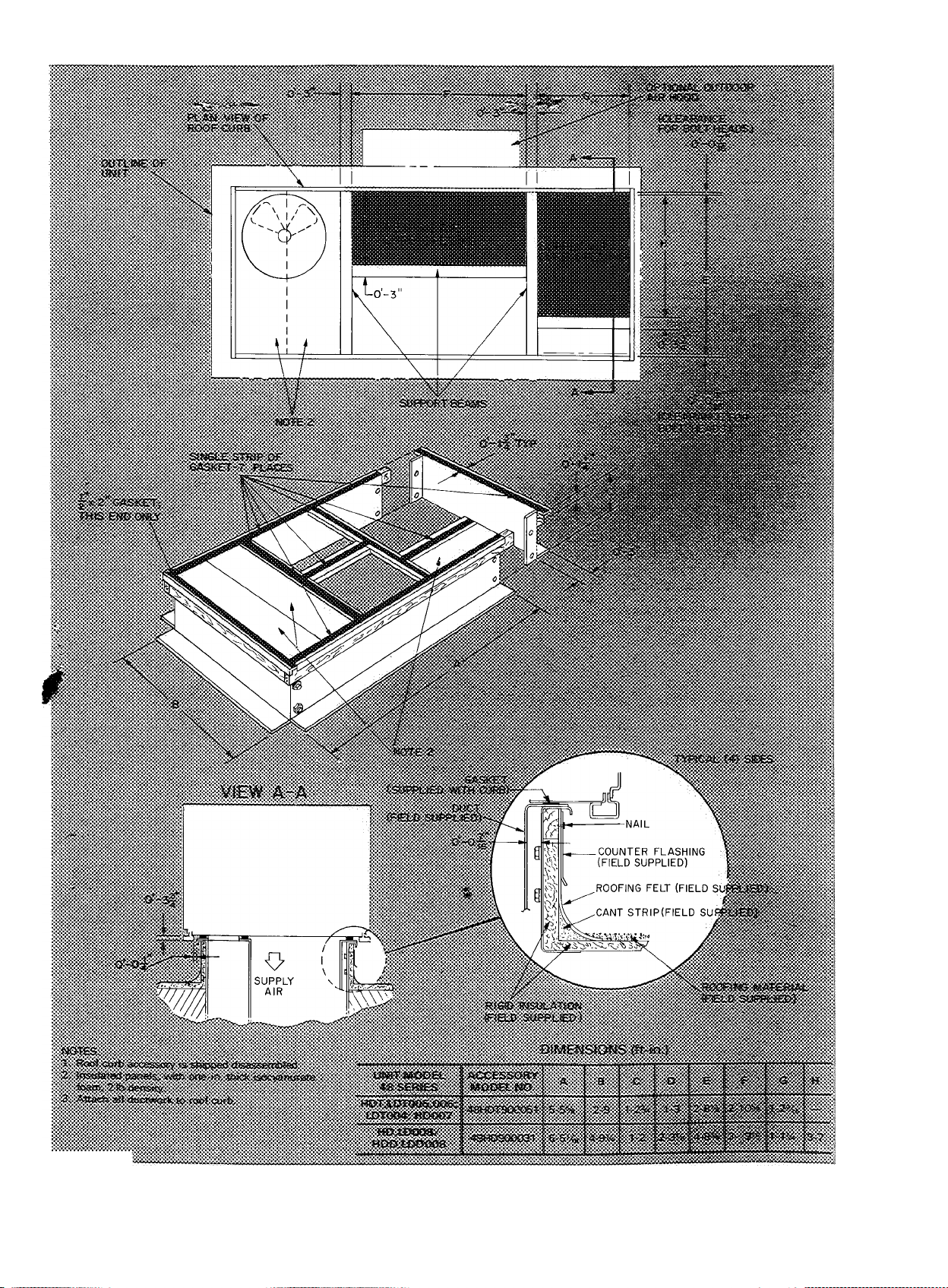
Fig. 1 — Roof Curb Details
Page 3

#
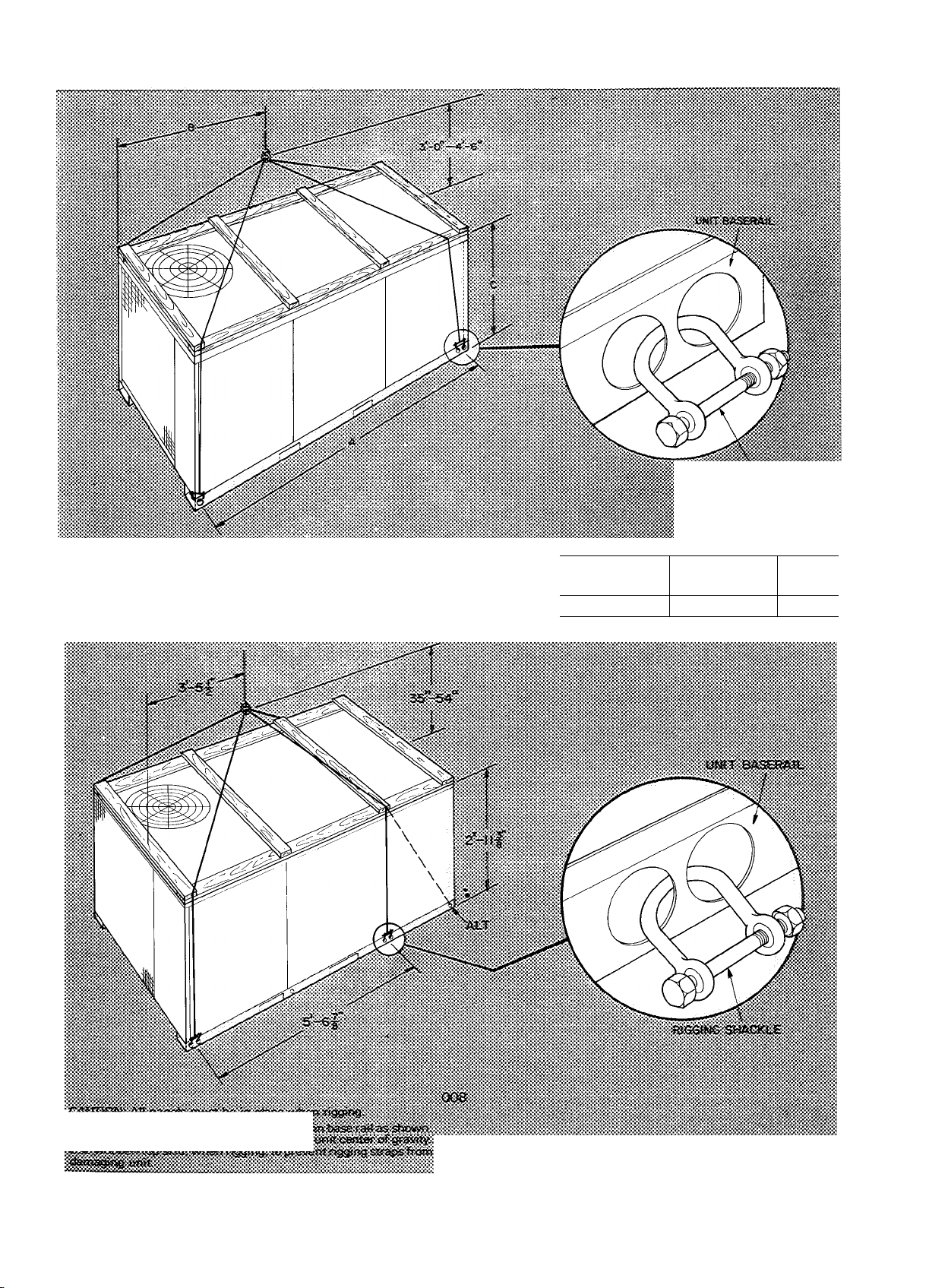
Spreader bars are not required if top crating is left
on unit. Rollers may be used to move unit across a
roof. Level by using unit frame as a reference,
leveling tolerance is ± l/16in. per linear foot in
any direction. See Fig. 2 for additional information.
Weight is shown in Table 1.
Lifting holes are provided in base rails as shown in
Fig. 2. Refer to rigging instructions on unit.
POSITIONING — Maintain clearance around and
above unit to provide minimum distance from com
bustible materials, proper airflow and service access.
See Fig. 3 and 4.
Do not install unit in an indoor location. Do not
locate unit air inlets near exhaust vents or other
sources of contaminated air.
Although unit is weatherproof, guard against
water from higher level runoff and overhangs.
Locate mechanical draft system flue assembly at
least 48 in. from any opening through which com
bustion products could enter the building, and at
least 48 in. from an adjacent building. When unit is
located adjacent to public walkways, flue assembly
must be at least 7 ft above grade.
After unit is in position, remove polyethylene
shipping wrapper and rigging skids.
Step 4 — Install Flue Hood — Flue hood and
screen are shipped screwed to the basepan in furnace
compartment. Remove from shipping location and
using screws provided, install flue hood and screen
in location shown in Fig. 3 or 4. On 48LDT004-006
units, a flue restrictor plate MUST be assembled to
the flue discharge. The plate is shipped with the flue
hood package. Install as shown in Fig. 5.
Step 5 — Trap Condensate Drain — See Fig. 3 or
4 for drain location. A 7/8-in. preformed drain hose
is shipped clamped to the indoor basepan. At instal
lation, re-route the hose so it passes through the hole
in the indoor basepan and unit base rail.
When installed properly, the hose protrudes
through the base rail one inch. Replace clamp over
the hose where hose passes through the basepan to
ensure that hose remains level. Use a trap at least
4 in. deep and provide protection for trap against
freeze-up.
Step 6 — Install Gas Piping — Unit is equipped
for use with type of gas shown on nameplate. Refer
to local building codes, or, in the absence of local
codes, to ANSI Z223.1-1980 entitled National Fuel
Gas Code.
Natural gas pressure at unit gas connection must
not be less than 5 in. wg or greater than 13.5 in. wg
while unit is operating.
Size gas supply piping for O.Sin.wg maximum
pressure drop. Do not use supply pipe smaller than
unit gas connection. See Fig. 6 for typical pipe guide
and location of external manual main shutoff valve.
For LP gas units, pressure at unit gas connection
must not be less than 12in. wg or greater than
13.5 in. wg.
A 1/8-in. NPT plugged tapping, accessible for test
gage connection, must be installed immediately up
stream of the gas supply connection to the furnace.
Step 7 — Make Electrical Connections
FIELD POWER SUPPLY
004,005,006,007 — All units except 208/230-volt
units are factory wired for the voltage shown on the
nameplate. If the 208/230-v unit is to be connected
to a 208 power supply, the transformer must be re
wired by connecting the blue wire to C-13 and the
red wire to C-DUl.
48HDD,LDD/ HD,LD008 — 230- and 460-volt
units are factory wired for the voltage shown on
nameplate. If unit will be connected to a 208 power
supply, the transformer
ing the black wire to the 200-volt lead and insulating
the 230-volt lead.
48HHD,LHD/HH,LH008 — 230- and 460-volt
units are factory wired for the voltage shown on
nameplate. If 208/ 230-voIt unit will be connected to
a 208 power supply, the transformer must be rewired
by connecting the blue wire to C-13 and red wire
to C-DUL
All Units — Refer to unit label diagram for addi
tional information. Pigtails are provided for field
service. Use factory-supplied splices or ULapproved copper/aluminum connector.
When installing units, provide a disconnect per
NEC.
All field wiring must comply with National Elec
trical Code and local requirements.
Install conduit connectors in side panel openings
indicated in Fig. 3 or 4. Route power lines through
connector to terminal connections as shown in
Fig. 7.
Voltage to compressor terminals during opera
tion must be within voltage range indicated on unit
nameplate (also see Table 2). On 3-phase units,
voltages between phases must be balanced within
2% and the current within 10%. Use the formula
shown in Table 2, Note 2 to determine the % voltage
imbalance. Contact local power company for cor
rection of improper voltage or phase imbalance.
Operation on improper line voltage or excessive
phase imbalance constitutes abuse and may cause
damage to electrical components. Such operation,
would invalidate any applicable warranty.
FIELD CONTROL WIRING ^ Install a Carrierapproved accessory thermostat assembly according
to installation instructions included with the acces
sory. Locate thermostat assembly on a solid wall in
the conditioned space to sense average temperature.
must be rewired by connect
Page 4
=-=^--A ;y.
'iigSBEf^^ L..'^ • I
. .^ s 1
: _ __
' ‘x-b*’
I
L
.%'^CTO^^jNf<»i'pT79W’^ifl^W99«<%CMSiW».wW.w3^‘fW«<v?0%''Xww^
■•s .• s
Fig. 2 — Rigging Details
Page 5
Table 1 — Physical Data
UNIT SIZE 48 SERIES 004
OPER WT (lb)
Unit
with Economizer
Roo f Curb 130 130
COMPRESSOR
Qty Type
Oil (oz)
REFRIG (R-22) Capillary Contre
Cha rge (lb) 61
COND COIL
Row s
Fins/in 170
Total F ace Area (sq ft) 6 3
COND FAN
Nom Cfm 2200 3100
Qty Diam (in ) 1 22
Motor Hp
Motor Rpm
EVAP COIL
Row s 2 2
Fins/in
Total F ace Area (sq ft) 5 33 5 33
EVAP FAN
Qty Size (in ) 1 10x10 1 10x10
Type
Nom Cfm
Motor Hp Std
Nom M otor Rpm
Std/Opt Low 800/ 890
Rpm Range Std
Motor Pulley
Pitch D iam
(in )
Fan Pulley
Pitch D iam
(in )
Belt. Q ty Type. Length (in
Speed Change per Full
Turn of Moveable
Pulley Flange (Rpm )
Moveable Pulley
Max Full Turns
from C losed Position
Factory Setting Std
Full Turns Open Opt
Factory Speed Setting Std
(Rpm) Opt
FUR NACE SECTION
Tem p Rise (F)
Heating Input (Btuh)
Output Cap (Btuh)
Burner Orifice D iam
(in . drill size)
Natural Gas
Pilot Orifice Diam
(in drill size)
Natural Gas
Thermostat Heat Anticipator
Setting 460 v
HIG H-PRESS SWITCH
Cutout (psig)
Reset (psig)
LOW -PRESS SW ITCH
(Suction Line)
Cutout (psig)
Reset (psig)
AIR INLET SCREEN S
Qty. Size (in )
RETURN AIR FILTERS
Qty Size (in )
High
208/230V
LDT
630
655
1 M4023E
42
2
%
850 1075
140 140
DD DD
1200 1500
Opt 3/4
'/3
— —
850/1050 1000
—
— —
LDT HDT
30-60
80,000
61,600
Std
Opt
Std
Opt
Std
Opt
Opt
005 006
HDT ] LDT HDT LDT HH
650 630
675 1 655 685 665
1 P53260 1 P6026B 1 P60-6- 1 P77
66
660
640 660 640 720 720
130
66
48 72 7 2 I 9 3 99
2
170 140
6 3
1 22 1 22
’/2 ’/2
3/4
— —
890 1000
—
35-65
120,000
92,400
LDT HDT
30-60
80,000
61,600
9 73 9 73 108 15 6
3800
1075 1075 1075 1075
140 140 140 13 9
5 33
HDT LDT
1 11x10
35-65
1 20,000
92,400
1 11x10 1 11x10 1 11x10 1 11x10 1
DD DD BD
2000 2000
1
—
1130 1050/1130
— —
—
3/4
1
—
890/1000
—
LDT HH
30-60
80,000
61,600
1 2
1 0
27 ± 4
67 ± 7
1 32x19xV2
1 16x25x1
1...20x25x1
006
LH
— —
— —
74 74
Copper Tube, Aluminum Plate Fins
Copper Tube, Aluminum Plate Fins
2 : 2
14 0 140 139
Propeller Type
3800
1 22 1 22 22
’/2 '/2
3 A
5 33 6 3 8 2
HH LH
DD
2000
’/2
3/4
1725
__
—
630- 960
796-1130
1 9-2 9
2 4-3 4
5 2
5 2
66
66
830
995
35-65
120,000
92,400
2
2
2000
3/4
1 1
_
890/1000
1050/1130
-
—
LH HD
30-60
80,000
61,600
007
HD HH
745
130
_
—
HD.HH
890
950 (HD)
125 (HD)
008
946 (LD)
125 (LD)
1 Hermetic
124
LD.LH
886
4000
BD
2200
3/4
1725
796- 130 838-1032 (@ 2 turns open)
930-1260 352-11 27 (@ 1 turn open)
2 4-3 4
2 8-3 8
5 2
5 2
1 A 43
66
66
2
2
995
35-65
120,000
92,400
113 0
120,000
HD.HH LD.LH
HH
35-65
92,400
35-65
203 ,000
160 ,370
132 29 113 33 132 29
036 64 033 66
15-45
114 ,000
91,200
008
HDD.H LD
945 941
1005(HDD)
125 (HDD)
2 P46
6 2 per system
4500
’/2
3
12x12
BD
3000
1 0
1 5
—
_
—
2 4-3 4
2 4-3 4
50
5 0
65
69
4
4Y2
907
885
HHD.HDD LDD.LHD
35-65
203 ,000
160 ,370
036 64
1 2
1 0
426 ± 7
320 ± 20
27 ± 4
67 ± 7
2 16x20x1
2 20x20x1
124
LDD.LHD
996 (LDD)
125 (LDD)
15-45
114 ,000
91,200
113 33
033 66
#
DD — Direct Drive
Page 6
-----
------
■■ . •* .*
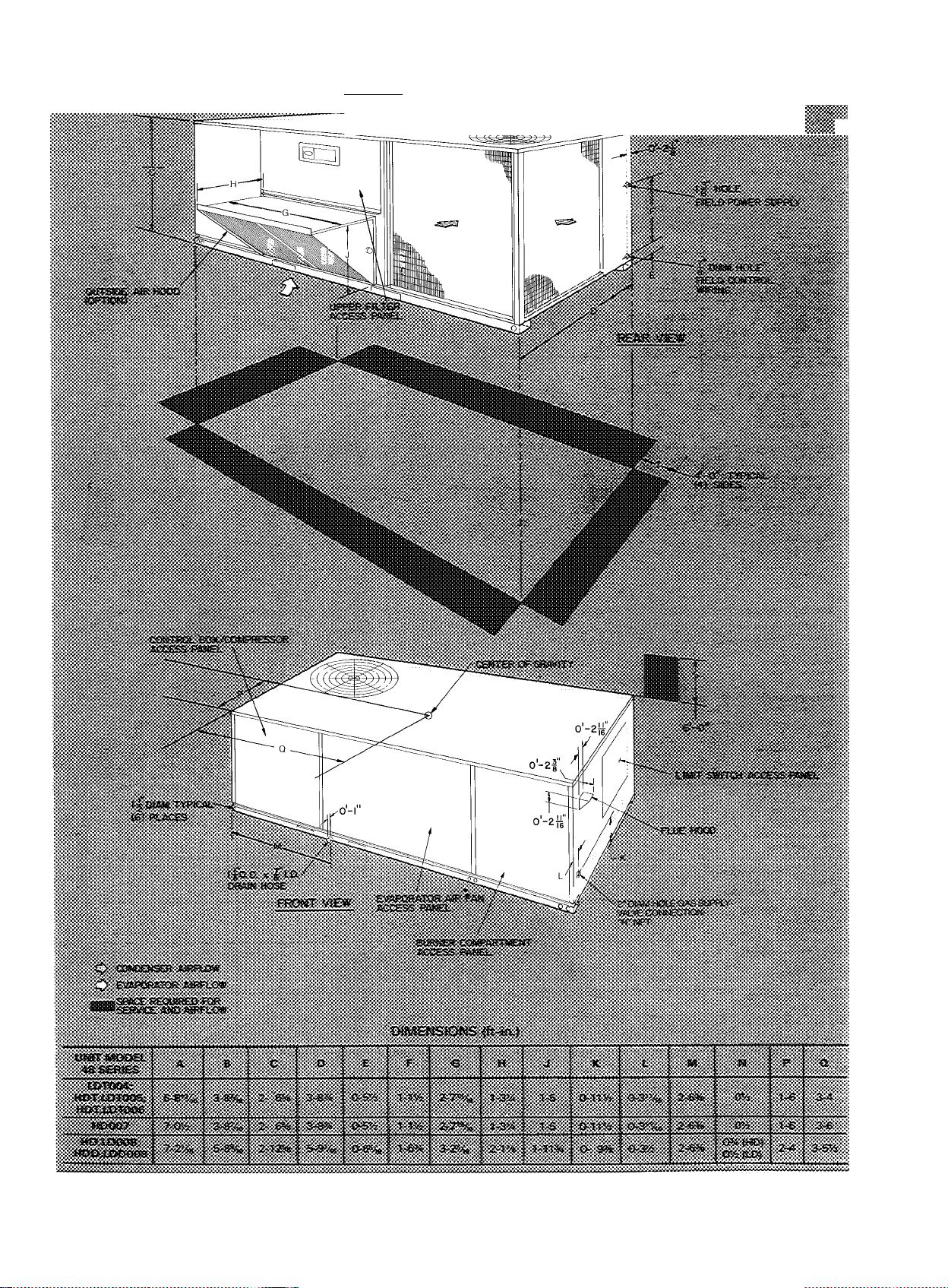
Fig. 3 — Downshot Base Unit Dimensions
Page 7
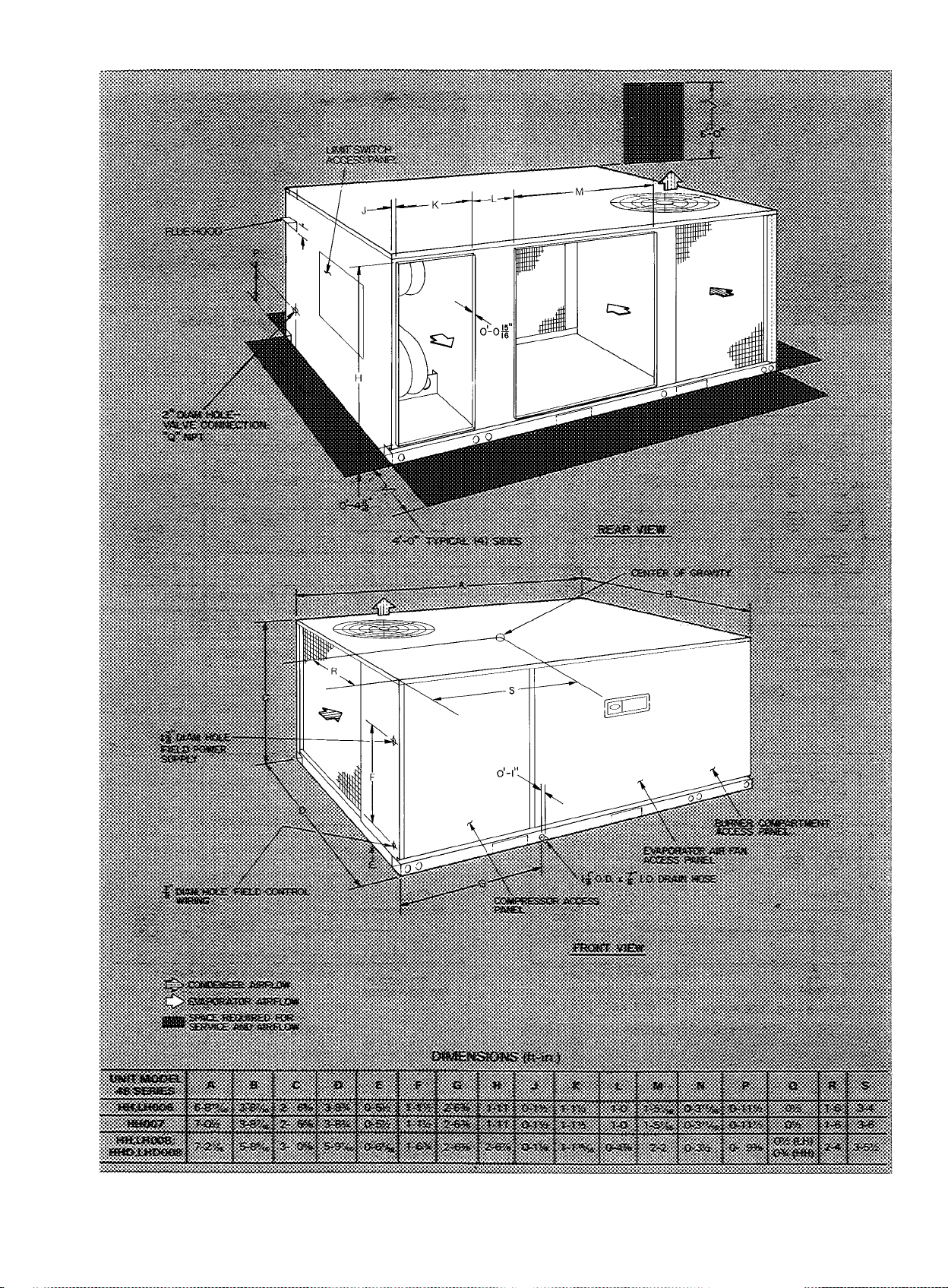
Fig. 4 — Horizontal Base Unit Dimensions
Page 8
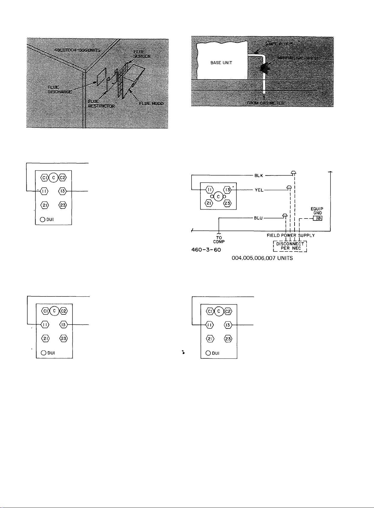
Fig. 5 — Flue Hood Details;
48LDT004-006 Units
BLK-
*NPT plug is field supplied
NOTE Follow all local codes
Fig. 6 — Gas Piping Guide
-YEL
-i?
FIELD POWER SUPPLY
'“dTsconnectI
230-1-60 u_PifLNJc_l
004,005,006,007 UNITS
BLK
TO
COMP
208/230-3-60 (SEE NOTE)
■ YEL •
BLU-
FIELD POWER SUPPLY
I
I
I
44
roTsCONNECT"!
PER NEC
004,005,006,007 UNITS
I
-------
I
I—dn
I
H--------
EQUIP
GND
UM
EQUIP
GND
TO INDOOR
FAN CONTACTOR
BLK •
■ YEL ■
-BLU-
FIELD POWER SUPPLY
008 UNITS
I
I
I
-+
Ti^sconne'ct”!
I
PER NEC
EQUIP
--Q®]
I
H--------
I
GND
■ Factory Wiring
. Field Wiring
NOTE If connected to 208-v power supply, rewire unit transformer
no 1 by
1 Connecting blue wire from transformer no 1 to C-13
2 Connecting red wire from transformer no 1 to C-DUl
Fig. 7 — Power Wiring Connections
8
Page 9

Table 2 — Electrical Data
UNIT
48 SERIES
LDT004
HDT/LDT005
HDT/LDT006
LH006
HH006
HD/HH
007
HD.LD/
HH.LH
008
HDD.LDD/
HHD.LHD
008
VOLTAGE
VOLTS-PH-HZ
208/230-1-60
208/230-3-60 187 254
460-3-60 414
208/230-1-60 197 254
208/230-3-60 187 254
460-3-60
575-3-60 517
230-1-60 207 254
208/230-3-60 187 254
460-3-60 414 508
575-3-60 517
230-1-60 207 254
208/230-3-60 187 254
460-3-60 414
575-3-60 508 623
208/230-3-60 187 254
460-3-60
575-3-60 518 632
208/230-3-60 187 254
460-3-60 414
575-3-60 518 632
208/230-3-60 187 254
460-3-60
RANGE
Min Max RLA LRA
254
197
508 7 6
414
508
633
633
508
414
508
508
414
508
COMPR
22 2 100 1 2 2
15 1 100 1 22
28 1 106 1
18 3 105
9 2 35 1
8 3 41
28 5
20 9
104
8 3 41
28 5
20 9
104
8 3
26 7
12 1
9 6
32 5
15 2 91 1
15 8
15 2
(ea)
7 2
(ea)
OUTDOOR
FAN MTR
Qty FLA
36 5 1 1 1
1
1 2 9 75
130 1
98 1 2 9
49 1
1
130 1
98 1
49 1
41 1
137 1
69 1
51 1 2 9 1 00
183
1 2 9
1 1 5
73 3 1
80
1
(ea)
35
1
(ea)
29
29
1.5
29
1 5
29
29
29
1 5
29
29
1 5
1 5
29
1 5
INDOOR
FAN MTR
FLA
Hp
33753 6
33'^
75
"33
.75
75 6 9 .90
75
.75 3 5 .57
75
1 006980
75
1 00
75
1 00
75
1 008069
50
75
50
75
50753 5
507569
75
1 00
75
1 00
1 0
1 5
1 0
1 5
1 0
1.5
1 0
1 5
1 0
1 5
69
3 6
6 9
3.5
6 9
6 9
69
80
3 5
40
69
80
69
80
40
80
3 6
48
1 8
2 4
7 5
5 4
6 0
2 7
3 0
1 4
2 1
48
6 5
24
33
COMBUSTION
FAN MTR
FLA
90
90
57
.90 35
90 19
90
90 40/40
57
90 30
90
90 40/40
57
90 30
90
57
90 22 4
90
57
57
90
57
MCA
30/30
50/50 60/60
POWER SUPPLY
MOCP (Amps)*
40
15
46
20
55
20
55
20
40
42
18 5
19 5
25
25
26
43
45
21
22
50
45/45
25
60
45/45
25
20
50
45/45
25
45
50
45/45
25
45
60
30
30
35
35
40
50
50
25
25
#
FLA — Full Load Amps
LRA — Locked Rotor Amps
MCA -- Min imum Circuit Amps (for wire sizing) Complies with
NOTES
1 In compliance with NEC requirements for multimotor and
2 Unbalanced 3-Phase Supply Voltage
NEC, Section 430-24
combination load equipment (ref NEC Articles 430 and 440),
the overcurrent protective device for the unit shall be fuse only
Never operate a motor where a phase unbalance in supply volt
age IS greater than 2% Use the following formula to determine
the % voltage unbalance
% Voltage Unbalance
= 100 X-
max voltage deviation from average voltage
average voltage
Supply voltage is 460-3-60
AB = 452 volts
BC = 464 volts
AC = 455 volts
Average Voltage
452 + 464 + 455
1371
3
457
MOCP — Maximum Overcurrent Protection
RLA — Rated Load Amps
'Fuse only
Determine maximum deviation from average voltage
(AB) 457 - 452 = 5 volts
(BC) 464 - 457 = 7 volts
(AC) 457 - 455 = 2 volts
Maximum deviation is 7 volts
Determine % voltage unbalance
% Voltage Unbalance = 100 x = 1 53%
This amount of phase unbalance is satisfactory as it is below
the maximum allowable 2%
457
iMPORTAKT' if
ffsofe
Page 10

THERMOSTAT
Factory Wiring
---------
Field Wiring
Fig. 8 — Control Wiring Connections
Route thermostat cable or equivalent single leads
of colored wire from subbase terminals through con
nector on unit to low-voltage connections as shown
in Fig. 8.
NOTE: For wire runs up to 50ft, use no. 18 AWG
insulated wire (35 C mininum). For 50 to 75 ft, use
no. 16 AWG insulated wire (35 C minimum).
Pass the control wires through the hole provided
in the corner post; then feed wires through the race
way built into the corner post to the 24-v barrier
located on the left side of the control box.
HEAT ANTICIPATOR SETTINGS — Set heat
anticipator settings at 1.20 for 460-voIt units and
1.00 for 208/ 230-volt units. Settings may be changed
slightly to provide a greater degree of comfort for a
particular installation.
Step 8 — Make Outdoor Air Inlet Adjustments and Install Outdoor Air Hood
OPTIONAL OUTDOOR AIR DAMPER
48HDT,LDT004,005,006 and HD007 — Optional
outdoor air damper is shipped with hood broken
down inside of unit. See Fig. 9.
Assembly
1. Remove filter access panel.
2. Remove sheet metal parts from filter area.
3. Using screws provided, a.s.semble sides to the
inside of the hood. See Fig. 9.
4. Discard baffle.
5. Install damper blade by inserting threaded pins
through hole in side plates.
6. Use wing nuts provided to hold blade in place.
7. Install outdoor air hood assembly, using screws
provided.
8. Install outdoor air inlet screen and screen
retainer.
9. Replace access panel.
Fig. 9 — Outdoor Air Damper and Hood
Installation and Details
(004,005,006.007 Units)
Fig. 10 — Access Panel Location
(008 Units)
lO. Loosen wing nut on side plate to adjust blade.
Adjust damper blade to desired setting for out
side air intake.
48HD,LD/ HDD,LDD008 — Optional outdoor air
damper is shipped with hood broken down in unit
filter section. See Fig. lO.
Assembly
1. Remove protective cover from unit. See Fig. lO.
2. Remove upper filter aecess panel (save screws).
See Fig. lO.
3. Remove hood parts from unit evaporator fan
and filter area. Assemble hood top and side
plates as shown in Fig. 11. Do n ot atta ch hood
to u ni t a t th is tim e .
4. Adjust outdoor air damper blade to desired
setting for outside air intake by releasing linkage
rod setscrew and adjusting linkage rod. See
Fig. 12. Secure damper blade in desired position
with setscrew.
5. Remove screws holding manual outdoor air
damper to unit. See Fig. 13.
lO
Page 11

Install outdoor air hood assembly, using screws
from step 5. These screws secure the manual
outdoor air damper assembly and the outdoor
air hood to unit. See Fig. 13.
7.
Slide outdoor air inlet screens into screen tracks
on hood side plates. While holding screens in
place, fasten screen retainer to hood using screw
provided. Make sure bottom edge of screens rest
inside base rail as shown in Fig. 14.
Replace upper access panel with screws saved
from step 2.
Fig. 11
Outdoor Air Hood Details
(008 Units)
MANUAL OUTDOOR
AIR DAMPER ASSEMBLY
!»>•■ LINKAGE ROD BLADE
LINKAGE
ROD SETSCREW
Fig. 12 — Damper Blade Adjustment
(008 Units)
Fig. 14 — Outdoor Air Hood Installed
(008 Units)
<2> ®
0
0
0
(rXjF^
0
0
0
0
0
m
6RN/YEL
1
1
TBI
C — Contactor Compressor
CLO — Compressor Lockout
IDR — Induced Draft Relay
IFC — Indoor Fan Contactor
_ _
(D ®
<2> ®
® ©•
TRAN^
^ '0*
<n> <®
o@o
® <§>
XCLO
(D
(D
LEGEND
<n> <Ì3>
□
FUSE-
IFR — Indoor Fan Relay
TB — Terminal Block
TDR — Time-Delay Relay
TRAN — Transformer
Fig. 15 — Control Box Details
(008 Units)
EQUIPMENT
GROUND
Viol
a
Fig. 13 — Manual Outdoor Air Damper
(008 Units)
OPTIONAL ECONOMIZER
48HDT,LDT004.005.006/ HD007
1. Remove upper filter access panel (save screws).
See Fig. \b.
2. Remove economizer hood parts from unit filter
area, and assemble leaving out the damper
blade. See Fig. 17. Remove tape from baro
metric relief damper.
3. Remove indoor blade linkage retaining strap
(Fig. 18). Place washer on linkage rod supplied
with accessory. Place linkage rod into hole “B”
of outdoor damper blade. Secure rod with blue
retaining clip provided.
11
Page 12

4. Remove mixed air thermostat (MAT.) capillary
retaining strap and stretch capillary through
notch in filter support. See Fig. 19. Route
through hook on upper left side of indoor coil
and secure end of capillary to retainer on lower
right side of indoor coil.
5. Fasten baffle to left side of damper plate with
round head screws provided. See Fig. 19.
6. Set vent position of damper by turning base unit
power on and allowing only the indoor fan to
run. Adjustment is made on left side of damper
motor by loosening vent position setscrew and
moving vent position lever back towards indoor
coil to CLOSE DAMPER or forward to OPEN
DAMPER. Once adjustment is made, retighten
setscrew and turn indoor fan off.
HOOD
UPPER FILTER
ACCESS PANEL
ACTUATOR
MOTOR
LINKAGE ROD
RETAINING STRAP
INDOOR DAMPER BLADE
Fig. 18 — Removing Indoor Blade Linkage
Retaining Strap (004,005,006,007 Units)
OUTDOOR AIR
INLET SCREEN
AIR SCREEN
RETAINER
Fig. 16 — Removing Economizer Upper Filter
Access Panel (004,005,006,007 Units)
DAMPER FILTER
MOTOR SUPPORT
• BAROMETRIC
RELIEF DAMPER
NOTCH
BASE UNIT
RECEPTACLE
Fig. 19 — Economizer
(004,005,006,007 Units)
7. Remove 4 screws holding economizer to unit.
Use screws to fasten hood to front of econo
mizer section.
MIXED AIR
THERMOSTAT
CAPILLARY
Fig. 17 — Economizer Hood Installation
and Details (004,005,006,007 Units)
8. Remove tape from outdoor air thermostat
(OAT.) and cooling lockout switch (CLS), and
fasten to inside of the hood with screws and
speed clips provided. See Fig. 20. Place knob,
12
Page 13

supplied with accessory, on OAT. and set for 3 F
below indoor room thermostat setting.
If accessory enthalpy control is used in lieu of
OAT., refer to instructions shipped with
accessory.
9. Place outdoor air inlet screen in hood and
secure with retaining bracket across hood front.
See Fig. 16.
10. Replace upper filter access panel with screws
saved from step 1.
POWER FAILURE — Dampers have a spring
return. In event of power failure, dampers close
until power is restored. Do not manually operate
damper motor.
48HD,LD/ HDD,LDD008 — Optional economizer
is shipped with hood broken down in unit filter
section. See Fig. 21.
Fig. 22 — Outdoor Air Hood Details
(008 Units)
#
SPEED CLIPS
OUTDOOR AIR THERMOSTAT
OR ENTHALPY CONTROL
OUTDOOR AIR HOOD SIDE PLATE
Fig. 20 — Enthalpy Control Position
(004,005,006,007 Units)
COOLING
LOCKOUT
SWITCH
(CLS)
BAROMETRIC RELIEF
DAMPER LOCATION
CLS — Cooling Lockout Switch
EC — Enthalpy Control
OAT — Outdoor Air Thermostat
BASE UNIT
RECEPTACLE
OUTDOOR AIR
INLET SCREENS (2)
Fig. 23 — Economizer Installed in Unit
(008 Units)
Assembly
1. Remove protective cover from unit. See Fig. 21.
#
Fig. 21 — Access Panel Location
(008 Units)
2. Remove upper filter access panel (save screws).
See Fig. 21.
3. Remove hood parts from unit evaporator fan
and filter area. Assemble hood top and side
plates as shown in Fig. 22. Remove tape from
barometric relief damper (see Fig. 23). Do not
atta ch hood to unit at this tim e. Put aside
baffle, screen retainer and retainer screw for
later assembly.
13
Page 14

DRIVE
SHAFT
OUTDOOR BLADES (2)
MOTOR
ACCESS
HOLE
^FOR VENT
¡^POSITION
i SETSCREW
BAFFLE
ECONOMIZER ASSEMBLY
OUTDOOR DRIVE LINKAGE
Fig. 24 — Economizer Details (008 Units)
PINK WIRE
VIOLET WIRE
TERMINAL D
Fig. 25 — Economizer Motor Connections
(008 Units)
4. Determine if vent air is required in building to
be conditioned. If so, check for percentage of
vent air needed and record quantity for vent
adjustment in step 11.
5. Remove jumper plug from base unit receptacle
and discard. Insert economizer plug into recep-
. tacle. See Fig. 23.
Steps 6 through 8 involve releasing and adjust
ing indoor damper blades from factory set
position.
6. Release indoor blades drive linkage by loosen
ing linkage connector setscrew at indoor crankarm on drive shaft. See Fig. 24.
Remove pink wire from economizer damper
motor terminal D and temporarily tape bare
wire end.
Remove violet wire from economizer damper
motor and connect to terminal D on economizer
damper motor. See Fig. 25.
7. Jumper red (base unit 24-v power) and black
wires in 24-volt control box compartment. See
Fig. 10 and 12.
DAMPER PLATE
BASE RAIL
Fig. 26 — Baffle Installation Details
(008 Units)
...............
iiSiSKiSSi
Fig. 27 ~ Vent Position Setting Details
(008 Units)
Turn on base unit power to energize evaporator
fan. The economizer’s outdoor blades should
open completely.
8. Adjust the indoor blades drive linkage so that
indoor blades are fully closed. Tighten the
linkage connector setscrew. Turn off base unit
power. Reconnect pink and violet wires to
economizer motor, as shown in Fig. 25.
9. If vent air is required, leave red and black wires
jumpered. If vent air is not needed, remove
jumper between red and black wires.
10. Fasten baffle to left side of damper plate with
round head screws provided. See Fig. 26.
11. If vent air is not required, go on to step 12. If
vent air is required, proceed as follows:
a.b.Turn on base unit power. This energizes the
evaporator fan motor.
Slide economizer out of unit so that access
hole to vent position setscrew is visible. See
Fig. 27.
#
14
Page 15

- " ■■ 'OUTDOOR AIR VhERMOSTAT
' (TERMINALS ARE UP)
il:TERMINALS :;i-:;Sv TTyT,;'
&s;i® COOLING lockout
.................................i SWITCH
iismM
c. Adjust vent opening by loosening vent posi
tion setscrew on left side of economizer
damper motor and setting vent position
lever to adjust damper (see Fig. 27). Move
vent position lever back toward evaporator
coil to close damper or forward to open
damper. When adjustment is completed,
retighten setscrew.
d. Turn off base unit powerand removejumper
from red and black wires.
e. Slide economizer assembly back into unit.
12. Remove tape from outdoor air thermostat
(OAT.) and cooling lockout switch (CLS), and
fasten to inside of hood with screws and speed
clips provided. Make sure terminals on OAT.
are up. See Fig. 28.
............
•v\ ENTHALPY
. ! CONTROL\
ACCESSORY
I
CONTROL
>:¥
COOLING
LOCKOUT
v‘ X'^ SWITCH
HOOD
HOOD
Fig. 29 — Economizer and Outdoor Air Hood
Assembled to Unit (008 Units)
13. Fasten hood top and side plate assembly
(Fig. 29) and economizer to unit with screws
supplied. Before attaching, make sure bottom
of hood assembly is resting on top of unit base
rail.
14. Place knob supplied with accessory economizer
on OAT. See Fig. 28. Set for 3 degrees below
indoor room thermostat setting.
If accessory enthalpy control (EC) (Fig. 28) is
used in lieu of OAT., refer to instructions
shipped with accessory enthalpy control .for
installation and adjustment.
15. Connect OAT./EC and CLS per unit label.
See Fig. 30.
Connect 2 economizer wires to each switch
with quick-connects. Unit connecting wires are
shipped taped on outdoor blade. See Fig. 23.
16. Slide outdoor air inlet screens in hood screen
tracks. Secure screens with screen retainer
across hood front. Secure screen retainer with
screw provided. See Fig. 29.
Fig. 28 — Outdoor Air Thermostat/Enthalpy
Control and Cooling Lockout Switch
Installation (008 Units)
17. Replace upper filter access panel with screws
saved from step 2.
18. Turn base unit power on.
15
Page 16

PINK
CLS
SEE NOTE
EC
¡—0O^t5(3>-
PINK
RED
CLS — Cooling Lockout Switch
EC — Enthalpy Control
OAT. — Outdoor Air Thermostat
NOTE: When enthalpy control (EC) is installed, outdoor air thermo
stat (OAT ) is removed from economizer
Fig. 30 — Wiring Connections for Outdoor Air
Thermostat/or Enthalpy Control and
Cooling Lockout Switch (008 Units)
Step' 9 — Adjust Evaporator Fan Speed — On
! ^ OAT „
BLUE ■
48HDT,LDT004,005,006 and 48LH006 units, the
evaporator fan motor factory speed setting is shown
on label diagram affixed to base unit. If other than
faetory setting is desired, refer to label diagram for
motor reconnection.
On 48H H006 and all 007 and 008 units, fan motor
pulleys are factory set for speed shown in Table 1.
To change fan speeds:
1. Shut off unit power supply.
2. Loosen belt by loosening fan motor mounting
plate nuts.
3. Loosen movable pulley flange setscrew (see
Fig. 31).
4. Screw movable flange toward fixed flange to in
crease speed and away from fixed flange to
decrease speed. Increasing fan speed increases
load on motor. Do not exceed maximum speed
specified in Table 1.
5. Set movable flange at nearest key way of pulley
hub and tighten setscrew. (See Table 1 for speed
change for each full turn of pulley flange.)
To align fan and motor pulleys, loosen fan pulley
setscrews and slide fan pulley along fan shaft. Make
angular alignment by loosening motor from mount
ing plate.
To Adjust Belt Tension — Loosen fan motor pivot
bolts. Move motor mounting plate up or down for
proper belt tension (1/2-in. deflection with one
finger) and tighten pivot bolts. Adjust lock bolt and
nut on mounting plate to secure in fixed position.
Fig. 31 — Indoor Air Fan Pulley Adjustment
START-UP
Unit Preparation — Make sure that unit has been
installed in accordance with installation instructions
and applicable codes.
Return Air Filters — Make sure correct filters are
installed in filter tracks. See Table 1. Do not operate
unit without return air filters.
Outdoor Air Inlet Screens — Outdoor air inlet
screen(s) must be in place before operating unit.
Compressor Mounting — Compressors are inter
nally spring mounted. Do not loosen or remove
compressor holddown bolts.
Internal Wiring — Check all electrical connections
in unit control boxes. Tighten as required.
Refrigerant Service Valves — Each unit system
has 2 Schrader type service ports, one on the suction
line and one on the compressor discharge line. Be
sure that caps on the ports are tight.
Cooling — To start unit, turn on main power
supply. Set system selector switch at COOL and
fan switch at AUTO. Adjust thermostat to a setting
below room temperature. Compressor starts on
closure of contactor.
Check cooling effects at a setting above room
temperature. Check unit charge. Refer to Refrig
erant Charge in Service section.
Reset thermostat at a position above room tem
perature. Compressor will shut off.
TO SHUT OFF UNIT — Set system selector switch
at OFF position or reset thermostat at a position
above room temperature. Units are equipped with
Signal-LOC™ protection device. Unit shuts down on
#
L
16
Page 17

any safety trip, and indicator light on thermostat
comes on. Check reason for safety trip.
Compressor restart is accomplished by manual
reset at the thermostat by turning the selector switch
to OFF and then to ON.
Heating
1. Purge gas supply line of air by opening union
ahead of gas valve. When gas odor is detected,
tighten union and wait 5 minutes before
proceeding.
2. Turn on manual gas valve and unit electrical
supply.
3. Set system switeh selector at FI EAT and fan
switch at AUTO, or ON. Set heating temperature
lever at above room temperature.
4. The induced draft combustion air fan will start.
Pilot lights within 30 seconds. Refer to Service,
Pilot Light if pilots do not light.
5. Main gas valve will open and main burners ignite
within 2 minutes from the pilot light ignition.
Natural gas burners are factory adjusted and
should burn with a soft blue flame. Flame should
not lift off burner face. Refer to Service, Main
Burners, if required.
6. Adjust airflow to obtain a temperature rise with
in the range specified on the unit nameplate.
TO SHUT OFF UNIT — Set system selector switch
at OFF or set heating selector lever below room
temperature.
Safety Relief — A soft solder joint at the service
Schrader port provides pressure relief under
abnormal temperature and pressure conditions.
Ventilation (Continuous Fan) — Set fan and sys
tem selector switches at ON and OFF, respectively.
Indoor air fan operates continuously to provide
constant air circulation.
Economizer Operating Sequence
COOLING MODE — When there is no power
applied to the indoor fan motor, the outdoor
damper is closed.
If outdoor ambient temperature is above the
outdoor air thermostat (OAT.) setting, the OAT.
contact is open. No power is supplied to DR2. Upon
a first-stage call for cooling, the indoor and outdoor
fans and compressor energize. The economizer
goes to vent position.
If outdoor ambient temperature is below the
outdoor air thermostat (OAT.) setting, the OAT.
contact is closed and power is supplied to DR2
(normally open contacts close and normally closed
contacts open). Upon a first-stage call for cooling
through Y1, power goes through contacts 4 and 6 of
DR2 causing DRl to energize (normally open con
tacts close and normally closed contacts open). The
economizer switches from vent or closed position
to modulation mode.
Modulation is accomplished by using the mixed
air thermostat (MAT.) in conjunction with the stall
circuitry inside the actuator. If the mixed air
temperature is above the MAT. setting, C-Tl and
C-T2 are made causing the damper motor to open
(which causes the air temperature to fall). As the
mixed air temperature falls to the MAT. setting
(54 L), C-T2 opens causing the motor to stall. When
mixed air temperature goes 4L below the MAT.
setting, C-Tl opens causing the spring to close the
damper. This in turn raises the mixed air tempera
ture and causes C-Tl to again stall the motor into
a less than full open position. If over-shoot should
occur, this process would oscillate a few times until
the mixed air temperature stabilizes.
Upon a second-stage call for cooling through Y2,
power goes through contacts 1,3 and 5 of DR2 and
CLO and the compressor is energized. Mechanical
cooling is integrated with economizer cooling.
Economizer continues in modulation mode.
When outdoor ambient temperature goes below
50 E, the cooling lockout switch (CLS) opens and
mechanical cooling is locked out.
An economizer control thermostat (ECT) on the
evaporator coil guards against abnormally low
suction temperatures while operating mechanical
cooling in conjunction with economizer. Low
suction temperatures can lead to frost on the evap
orator coil. If frost buildup is detected, thermostat
de-energizes economizer, thus closing the outdoor
air damper. This raises air temperature entering the
evaporator coil and melts frost. Once frost is melted,
the economizer is re-energized.
When cooling load is satisfied, the damper motor
is de-energized causing the spring to close the
damper.
During unoccupied periods, if a field-supplied
night switch is used and is opened, the outdoor
air damper closes.
HEATING MODE — With no power applied to the
indoor fan motor, the outdoor air damper is closed.
Upon a call for heat through Wl, the indoor fan
contactor is energized and provides power to the
indoor fan motor and economizer.
If the night set-back switch is closed, the outdoor
dampers will open to the manually preset vent
position by power passing through contacts 1 and 2
of DR 1 and goingto switches SW1 and SW2through
terminal XV of actuator. The switches are set with
3 degree angular difference between each other,
acting as a dead spot or stall region. Thus, if the
damper is below vent position, SW2 is closed power
ing the damper open until SWl closes and SW2
opens which stalls the motor. If the damper is too far
open, both SWl and SW2 are open causing the
spring to close the damper until SWl closes, again
stalling the motor.
When heating load is satisfied, the damper motor
is de-energized causing the spring to close the
damper.
During unoccupied periods, if a night set-back
switch is used and opened, the damper closes.
17
Page 18

SERVICE
Cleaning — Inspect unit interior at the beginning
of each heating and cooling season or as operating
conditions require.
EVAPORATOR COIL
1. Turn unit power off. Remove indoor fan motor
access panel.
2. Diseonnect indoor motor wiring from main
control box.
3. Remove screws from base of fan motor housing.
4. Slide fan motor housing out of base unit.
5. Clean coil using a commercial coil cleaner
(i.e., Oakite 164) or dishwasher detergent in a
pressurized spray canister. Wash both sides of
coil and flush with clean water. For best results,
backflush toward return air section to remove
foreign material. Flush condensate pan after
completion.
6. Reinstall fan motor housing, reconnect wiring
and replace indoor fan motor access panel.
Fig. 34 — Separating Coil Sections
CONDENSER COIL — Inspect coil monthly.
Clean condenser coil annually, or as required by
location or outdoor air conditions.
Fins are not continuous through coil sections.
Dirt and debris may pass through first section,
become trapped between the 2 rows of fins, and
restrict condenser airflow. Shine flashlight through
coil to determine if dirt or debris has collected
between coil sections.
Fig. 32 — Cleaning Condenser Coil
Clean coil as follows:
1. Turn off unit power.
2. Remove top panel screws on condenser end of
unit. Remove screws from coil side of coil center
post. Do not remove center post.
3. Remove condenser coil corner post. See Fig. 32.
To hold top panel open, place coil corner post
between top panel and center baffle. See Fig. 33.
4. Remove device holding coil sections together at
return end of condenser coil. Carefully separate
the outer coil section 3 to 4 in. from the inner coil
section. See Fig. 34.
5. Use a water hose or other suitable equipment to
flush down between the 2 coil sections to remove
dirt and debris. Clean the outer surfaces with
a stiff brush in the normal manner.
»
6. Reposition the outer coil section, remove the coil
corner post from between the top panel and
center baffle. Secure the sections together. Install
the coil corner post, coil center post and replace
all screws.
CONDENSATE DRAIN — Check and clean each
year at start of cooling season. In winter, keep drain
and trap dry or protect against freeze-up.
Fig. 33 — Propping Up Top Panel
FILTERS — Clean or replace at start of each heat
ing and cooling season, or more often if operating
conditions require it.
OUTDOOR AIR INLET SCREENS (Downshot
Units) — Clean screens with steam or hot water
and a mild detergent. Do not use throwaway filters
in place of screens.
18
Page 19

TO USE COOLING CHARGING CHART ^
Take the outdoor ambient temperature and read the
suction pressure gage. Refer to chart to determine
what suction temperature should be. If suction tem
perature is high, add refrigerant. If suction tempera
ture is low, carefully blow some of the charge. Re
check the suction pressure as charge is adjusted.
Example; (Fig. 40)
Outdoor Temperature
...........................................
85 F
Suction Pressure............................................. 70 psig
Suction Temperature should be............................52 F
(Suction Temperature may vary ± 5 F.)
Fig. 35 — Condenser Air Fan Adjustment
Lubrication
COMPRESSORS — Each compressor is charged
with correct amount of oil at the factory.
FAN MOTOR BEARINGS — No lubrication of
condenser or evaporator fan motors is required for
first 5 years of operation. Annually thereafter, clean
and repack bearings with a suitable bearing grease.
Condenser Air Fan Adjustment (Fig. 35) — Shut
off unit power supply. Remove condenser fan
assembly (grille, motor, motor cover and fan) and
loosen fan hub setscrews. Adjust fan height as
shown in Fig. 35. Tighten setscrews and replace
condenser fan assembly.
Manual Outdoor Air Damper (Downshot Units
Only) — If outdoor air damper blade adjustment is
required, see Optional Manual Outdoor Air
Damper Section.
Economizer Adjustment (Downshot Units) —
Refer to Economizer section under Installation.
Refrigerant Charge — Amount of refrigerant
charge is listed on unit nameplate (also refer to
Table 1). Refer to Carrier Standard Service Tech
niques Manual, Chapter 1, Refrigerants.
Unit panels must be in place when unit is oper
ating during charging procedure.
NO CHARGE — Use standard evacuating tech
niques. After evacuating system, weigh in the speci
fied amount of refrigerant. (Refer to Table 1.)
LOW CHARGE COOLING — Using Cooling
Charging Chart, Fig. 36 through 41, vary refrigerant
until the conditions of the chart are met. Note the
charging chart is different from type normally used.
Chart is based on charging the units to the correct
superheat for the various operating conditions.
Accurate pressure gage and temperature sensing
device are required. Connect the pressure gage to the
service port on the suction line. Mount the tempera
ture sensing device on the suction line and insulate it
so that outdoor ambient temperature does not affect
the reading. Indoor air cfm must be within the
normal operating range of the unit (maximum 3750;
minimum 2250).
(A
<
O
g 620-
o 90
Ql
O
=i
^ 551
iii
tr
§483
iij
L.
: 345
276
207 30
80
60
50
20 30
40 50 60 70
SUCTION LINE TEMPERATURE (F)
-I 4 10 16 21
SUCTION LINE TEMPERATURE (C)
Fig. 36 — Cooling Charging Chart;
48LDT004
<
w620
<
0.
o
80
551
] 483
? 70
^414
:345-
276-
207 30
60
50
40
20 30
40 50 60 70
SUCTION LINE TEMPERATURE (F)
-I 4 10') 16 21
SUCTION LINE TEMPERATURE (C)
Fig. 37 — Cooling Charging Chart;
48HDT,LDT005
OUTDOOR TEMP
(F) (C)
115 46
105 41
95 35
85 29
75 24
1 1 1 1
65 18
(F) (C)
115 46
105 41
1 1 1 1 1
Mi tr
95 35
Mill
85 29
75 24
1 1 1 1 1
65 18
19
Page 20

- -
"414--' 60
207- 30
nilTnnnR
115 46
1 1 1 1
lOf 41
80
50
20
SUCTION LINE TEMPERATURE (F)
-7
SUCTION LINE TEMPERATURE (C)
30 40 50 60 70
-1 4 lb 16 21
IMI
9£ 35
4__L_U_
1 1 1 1
05 29
il 24
65 IB
III!
55 13
Fig. 38 — Cooling Charging Chart;
48HDT.LDT006; HH.LH006
TEMP
689
(/)
< 621
o
CO
s
0552
liJ
^483
cc
0-414
z345
O
’276-
207- 30
100
90
: 80
70
60
50
40
SUCTION LINE TEMPERATURE (0 )
- -
-
-
-
-
-
-
--
-
-
SUCTION LINE TEMPERATURE ( F)
-
20 30 40 50 60
-7 -Ì 4 lb 16
OUTDOOR TEMP
70 80
21
Fig. 40 — Cooling Charging Chart;
48HD.LD,HH.LH008
(F) (C)
115 46
105 41
95 35
85 29
75 24
65 18
55 13
45 7
- -
#
27
689
^552
r)
UÌ
llJ
(E
“-483
414
345
276
100
OUTDOOR TEMP
m 90
80
70
3 60
50
40
20 30 40 50 60 70
-7
SUCTION LINE TEMPERATURE (F)
-Ì 4 IÒ 16 2Ì
SUCTION LINE TEMPERATURE (C)
Fig. 39 — Cooling Charging Chart;
48HD,HH007
(F) (C)
105 41
95 35
85 29
75 24
OUTDOOR TEMP
(F) (C)
115 46
«620
90
<
551
a: 80
483
70-
276
207
60
50
40
30
20
30 4 0 50 60 70 80
-7
SUCTION LINE TEMPERATURE (F)
-Ì 4 IÓ 16 21 27
SUCTION LINE TEMPERATURE (C)
uj 414
2
Z
O
p345
o
3
«
80
27
105 41
95 35
85 29
75 24
65 18
Fig. 41 — Cooling Charging Chart;
48HDD.LDD.HHD,LHD008
L
20
Page 21

If Chargemaster® charging device is used, tem
perature and pressure readings must be accom
plished using the charging chart.
Main and Pilot Burners — At the beginning of
each heating season, inspect for deterioration or
blockage due to corrosion or other causes. Observe
the pilot and main burner flames and adjust, if
necessary, referring to automatic Pilot Adjustment
or Main Burners sections of instructions.
Flue Gas Passageways — Inspect flue collector
box and upper areas of heat exchanger cells by
removing burner compartment access panel; then
remove flue cover and inspect heat exchangers.
Using a wire brush, clean all surfaces as required.
Combustion Air Blower — Clean periodically to
assure proper airflow and heating efficiency. Inspect
blower wheel every fall and periodically during
heating season. For the first heating season, inspect
blower wheel bimonthly to determine proper clean
ing frequency.
To inspect blower wheel, remove draft hood and
screen. Shine a flashlight into opening to inspect
wheel. If eleaning is required, remove motor and
wheel as follows:
1. Remove burner access panel.
2. Remove the 6 screws that attach induced draft
motor mounting plate to blower housing
(Fig. 42). The mounting plate will drop down.
3. Remove the 4 wires attached to the motor and
remove assembly from unit.
4. To remove blower, remove setscrews.
5. To remove motor, remove blower, then remove
the nuts that hold motor to mounting plate.
NOTE; Do not lose spacers for induced draft
motor.
6. To reinstall, reverse the procedure outlined
above.
Limit Switch — Aceess panel is located on the heat
section side panel (Fig. 3 and 4).
004,005,006,007 UNITS AND 48HDD,LDD/HD,
LD008 UNITS — Limit switch is located in the
upper section of the heat exchangers. Bi-metal
sensor is facing the airstream. Remove bracket
holding limit switch and remove screw holding
switch.
48HHD,LHD/HH,LH008 UNITS ^ Limit switch
is located on partition between blower section and
heat section. Remove plate and screw holding
switch.
Pilot Light — If pilot does not light as described in
Start-Up, Heating: Be sure pilot orifice is not
obstructed, gas pressure is not less than 3in. wg;
and air has been bled from gas supply. Check for
spark ignitor malfunctions as follows:
1. Shut off unit power supply.
2. Check that spark gap is 1/8 to 3/16 inch.
3. Check that spark generator is securely grounded
to furnace vestibule plate.
4. Check that high-voltage lead is securely con
nected between generator and electrode body.
5. Restore power. Check that 24 volts is supplied to
primary side of generator.
6. Check unit label diagram for correct terminal
usage if any wires are removed.
Automatic Pilot Adjustment
1. Turn off unit power supply, set system selector
switch at HEAT, and adjust thermostat to call
for heat.
2. Remove burner compartment access panel.
3. Remove screw cap cover on the top of the main
gas valve to expose pilot adjusting screw.
4. With a small screwdriver, turn adjustment screw
until flame is approximately 1 to 1-1/2 in. high.
5. Replace screw cap cover on pilot gas valve.
6. Observe burner operation and adjust main gas
valve for correct burner operation as required.
See Fig. 43 for proper flame appearance.
7. Replace all panels.
Automatic Gas Valve Sequence of Operation
— Thermostat calls for heat, energizing the spark
ignitor and simultaneously opening the pickup and
hold solenoids of the pilot gas valve (inside main gas
valve). The pilot gas ignites within 2 seconds, stop
ping the ignitor. Within 11 seconds, the pilot contact
(normally closed) opens, drops out the pickup sole
noid. Within 35 seconds, the pilot contact (normally
MAIN
BURNER
SECTION
Fig. 42 — Burner Section Details
MAIN
GAS
VALVE
Fig. 43 — Proper Flame Appearance
21
Page 22

open) closes, energizing the heat motor in the main
gas valve. The main gas valve will open within
45 seconds.
Main Burners are factory set and should require
no adjustment. However, if burner adjustment is
necessary:
1. Perform Automatic Pilot Adjustment.
2. Turn gas valve to ON. Allow unit to operate at
least 15 minutes with furnace access panel in
place.
3. Remove access panel.
4. Loosen primary air shutter and adjust to a mini
mum opening of 5/8 inch.
5. Retighten primary air shutter and reinstall access
panel.
TO CHECK ignition of main burners and fan
switch operation, move thermostat dial above and
below room temperature several times pausing at
least one minute between cycles.
REMOVAL
1. Shut off manual main gas valve.
2. Shut off power to unit.
3. Remove evaporator air fan access panel, burner
compartment access panel and center post.
4. Disconnect gas piping at unit gas valve.
5. Remove (and mark) red wire from terminal no. 4
or W1 and brown wire from terminal no. 3 or C2
and violet wire from terminal W2 (connections
are dependent on whether a 2-stage or singlestage valve is on the unit).
6. Remove the 2 screws at rear of housing just
inside burner section.
7. Lift and slide assembly out.
REPLACEMENT
1. Slide assembly into burner section and push
snugly against vestibule plate.
2. Screw assembly down.
3. Connect red wire to terminal no. 4 or W1 and
brown wire to terminal no. 3 or C2 and violet
wire to terminal W2 (connections are dependent
on whether a 2-stage or single-stage valve is on
the unit).
4. Connect gas piping at unit gas valve.
5. Replace center post and access panels.
6. Turn on manual main gas valve.
7. Restore power to unit.
CLEANING
1. Remove burner assembly from unit as described
above.
2. Inspect burners and if dirty, remove by removing
retaining plate.
3. Using a soft brush clean burners as required.
4. Replace burners.
5. Replace burner assembly as described above.
Replacement Parts — A complete list of replace
ment parts may be obtained from any Carrier dis
tributor upon request.
22
Page 23

m
TYPICAL WIRING DIAGRAM LEGEND
AHA
—
Assy
C
CAP.
CC
CH —
CLO —
CLS
COMP
CS —
DM —
DR —
EC —
ECT
Equip
Fu
Gnd
HPS
1
IDM
IDR
IFC
IFM
IFR
IPP Ignitor Power Pack
L
LPS
LS
MAT.
MGV
Mtr
NS
OAT.
OFM
PGV Pilot Gas Valve
Adjustable Heat Anticipator
—
Assembly
—
Contactor Compressor QT -
—
Capacitor RLC —
—
Cooling Compensator RS —
Crankcase Heater Std —
Compressor Lockout Sw —
__
Cooling Lockout Switch TB —
—
Compressor Motor TC —
Centrifugal Switch
Damper Motor
Damper Relay
Enthalpy Control
—
Economizer Thermostat
Equipment
—
Fuse
—
Ground
High-Pressure Switch
—
—
Ignitor Electrode
—
Induced Draft Motor
_
__
Induced Draft Relay
—
Indoor Fan Contactor
Indoor Fan Motor
—
—
Indoor Fan Relay
—
Light
Low-Pressure Switch
Limit Switch
—
Mixed Air Thermostat
__
Main Gas Valve
Motor
Night Setback Switch
—
Outdoor Air Thermostat
—
Outdoor Fan Motor
(48HD,LD008)
PI PS —
TDR —
TH TRAN -
o
o
□
•o
—•—
_
_________
—
——
Plug Assembly
Pilot Sensor
Ouadruple Terminal
Rotor Locking Circuit
Rollout Switch
Standard
Switch
Terminal Block
Thermostat, Cooling
Time-Delay Relay
Thermostat, Heating
Transformer
Marked Wire
Denotes Connection Point Between
Subbase and Thermostat
Terminal (Marked)
Terminal (Unmarked)
Terminal Block
Field Splice
Splice (Marked)
Factory Splice
Factory Wiring
Internal Connection
Accessory or Optional Wiring
Field Control Wiring
Field Power Wiring
To indicate common potential only,
not to represent wiring
TYPICAL WIRING DIAGRAM NOTES
(48HD,LD008)
1. Compressor and fan motors are thermally pro
tected — 3-phase motors are protected against
primary single-phasing conditions.
2. If any original wires must be replaced, use 90 C
wire or equivalent.
3. Numbers indicate the line location of used con
tacts. A bracket over (2) numbers signifies a
single pole double throw contact. An underlined
number signifies a normally closed contact. Plain
(no line) number .^signifies a normally open
contact.
4. Must use thermostat HH07AT172 or 174 with
subbase HH93AZ177.
5. Set heat anticipators at one amp (208/230-3-60).
Set heat anticipators at 1.2 amp (460-3-60).
6. Factory connected to 230-v or 460-v lead per unit
rated voltage. If 208-v power supply is used,
connect to 200-v lead and insulate 230-v lead.
23
Page 24

ECONOMIZER ASSY.
<g>
DM ^
<T>
<£)
DM ^
<D
<E>
<±>®
0^j)D
TWO POSITION DAMPER MOTOR ASSY.
<0®
<2 >
<±> <£>
<E>
i®®'
L®fj
CLS
CiXD
OAT
to 1=0
EOT. LPS
HPS .ECT
CAP
o o
QT
BRN—
ORN/YEL
<i><D<]X^<l><»>
Q^El
PL I
o o
o
COMP
Typical Component Arrangement (48HO,LD008 Shown)
24
1PM
Page 25

1 H
1 гг
из
О 1
Page 26

-< ^
a.vt
C
5
o
£
w
00
o
0
Q
_l
Q
1
00
o
'■P
W
'q.
t-
(C
E
03
u
O)
c
(0
o
>•
5
For replacement items use Carrier Specified Parts.
Manufacturer reserves the right to discontinue, or change at any time, specifications or designs without notice and without incurring obligations
Book 1
Tab la 6a
4
Form 48H,L-7S1 Supersedes 48HD-5SI: 48H,L-4SI
Printed in U S A
9-84 PC 111 Catalog No 534-805
 Loading...