

Page 1
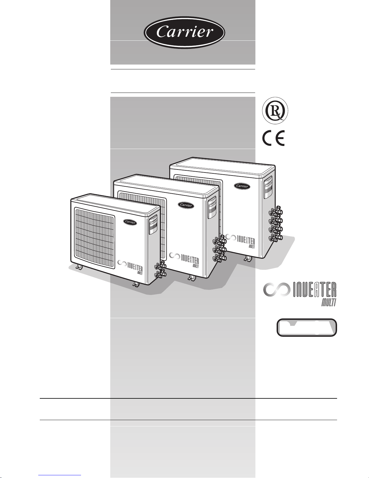
38VYM
•
L
L
O
Y
D
'
S
R
E
G
I
S
T
E
R
Q
U
A
L
I
T
Y
A
S
S
U
R
A
N
C
E
I
S
O
9
0
0
1
R-410A
INST ALLATION MANU AL
Page 2
GB - 1
38VYM
R-410A
Heat pump multisplit system outdoor unit
ENGLISH
For operation and maintenance instructions of this unit as well as installation
instructions of the indoor unit, refer to the relevant manuals.
Contents Page
Dimensions and weight.... .... .... ................................................................... 2
Minimum clearances................................................................................... 2
Connections................................................................................................ 3
Operating limits..... ... .... .... ........................................................................... 3
General information.... .... .... ........................................................................ 4
Warnings: avoid .... .... .... .... .... ...................................................................... 5
Refrigerant connections ........ .... ................................................................. 6/8
Electrical connections....... .... ...................................................................... 9/11
Electrical data ............................................................................................. 11
Incorrect wiring and piping procedure check..... ......................................... 12
Test procedure .... .... .... .... .... ........................................................................ 13
Pump-down................................................................................................. 13
Maintenance ............................................................................................... 13
Guide for the owner........ .... .... ..................................................................... 13
Accessories ................................................................................................ 13
R-410A – QUICK REFERENCE GUIDE
•R-410A refrigerant operates at pressures 50%-70% higher than R-22. Be sure that
servicing equipment and replacement components are designed to operate with R-410A.
•R-410A refrigerant cylinders are pink.
•R-410A refrigerant cylinders have a dip tube which allows liquid to flow out of cylinder in
an upright position.
•R-410A systems must be charged with refrigerant in liquid phase. Use a commercial
type metering device in the manifold hose in order to vaporize the liquid refrigerant
before it enters in the unit.
•R-410A, as other HFCs, is only compatible with oils selected by the compressor
manufacturer.
•POE oils absorb moisture rapidly. Do not expose oil to atmosphere.
•Never open system to atmosphere while it is under vacuum.
•Do not vent R-410A into the atmosphere.
•Use only Carrier matching indoor units.
Heat pump model Power supply
38VYM-18
38VYM-28 230V ~ 50Hz
38VYM-32
Page 3
38VYM
R-410A
GB - 2
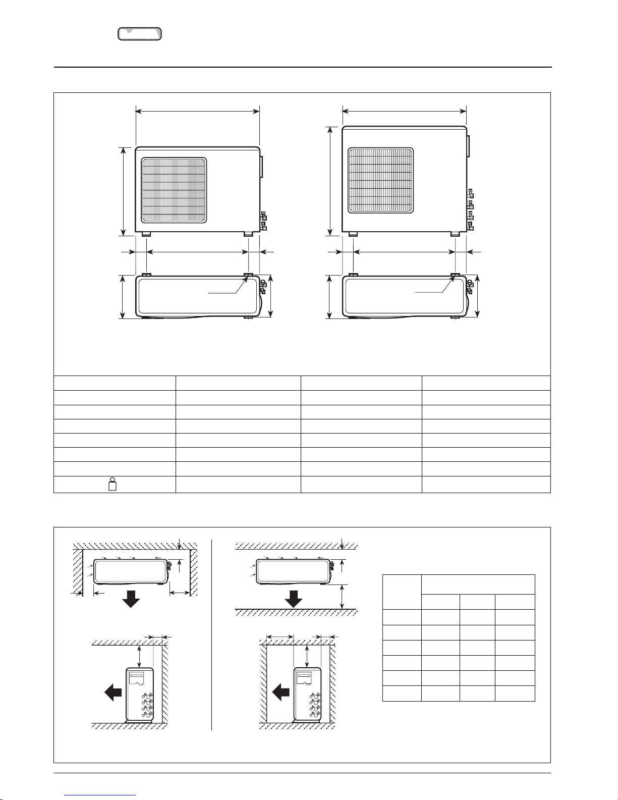
Dimensions, weight and minimum clearances
Dimensions and weight
Minimum clearances
B
A
C
D
E
F
A
F
DE
EED
B
C
F
A
Ø 8,5
EED
B
C
F
A
Ø 8,5
38VYM-18
Model 38VYM-18 38VYM-28 38VYM-32
A mm 800 800 800
B mm 590 800 800
C mm 300 300 300
D mm 508 508 508
E mm 146 146 146
F mm 330 330 330
kg
kg 50 64 65
38VYM-28 / 38VYM-32
Model
38VYM
18 28 32
A mm 100 100 100
B mm 250 250 250
C mm 500 500 500
D mm 100 100 100
E mm 670 670 670
F mm 400 400 400
Note:
For each installed system, the minimum clearance shown in the table only refers to the two configurations and arrangements illustrated.
Page 4
38VYM
R-410A
GB - 3
ENGLISH
Connections and operating limits
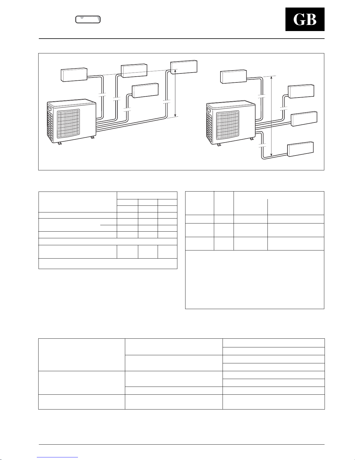
Connections
Table II: Operating limits
WARNING:
During heat pump operation the unit will undergo several defrost cycles to
eliminate ice that might collect on the outdoor unit at very low ambient
temperatures.
In these cycles, fan speed will automatically reduce or stop and cannot be
changed until defrost cycle is completed.
d.b. - dry bulb
w.b. - wet bulb
1) 38VYM-18: 15°C
2) 38VYM-18: –5°C
Cooling
Maximum conditions
Outdoor temperature 43°C
Indoor temperature 32°C d.b.; 23°C w.b.
Minimum conditions
Outdoor temperature 10°C
(1)
Indoor temperature 21°C d.b.; 15°C w.b.
Heating
Maximum conditions
Outdoor temperature 24°C d.b.; 18°C w.b.
Indoor temperature 27°C d.b.
Minimum conditions Outdoor temperature –10°C
(2)
Mains power supply Nominal single-phase voltage 230V ~ 50 Hz
Operating voltage limits min. 198V – max. 264V
햲 Outdoor unit
햳 Indoor unit A1
햴 Indoor unit A2
햵 Indoor unit A3
햶 Indoor unit A4
IMPORTANT:
Additional refrigerant charge is unnecessary.
This air conditioner is designed with chargeless specification.
For 38VYM-28 and 38VYM-32 models, connection of only one
indoor unit is not allowed.
Two or more units must be connected.
햲
햶
햵
A
4
A3
햴
A2
햳
A1
H
Table I: Connections
38VYM
18 28 32
Indoor unit
A1-A2
A1-A2-A3
A1-A2-A3-A4
Max. height difference
H m10 15 15
Pipe length
Max m20 25 25
per unit
Min m2 2 2
Total pipe length
Max m30 50 70
(Minimum number of bends possible)
Minimum number of indoor units
1
22
to be connected
(note)
Note:
when only one indoor unit is connected, the connection pipe must have
a minimum length of 5 m.
Pipe diameter
Liquid Gas
Indoor (Liquid) (Suction)
38VYM unit mm (inches) mm (inches)
18 A1, A2 6.35 (1/4”) 9.52 (3/8”)
A1 6.35 (1/4”) 12.70 (1/2”) (note 1)
28
A2, A3 6.35 (1/4”) 9.52 (3/8”)
A1, A3 6.35 (1/4”) 12.70 (1/2”) (note 1)
32
A2, A4 6.35 (1/4”) 9.52 (3/8”)
Notes:
1) When the indoor unit is as large as 009 or the model is 42HQM012,
use Ø 9,52 mm (3/8") pipes supplied with the flare tap adapter.
2) All fittings are flare type.
3) Use only refrigeration grade pipes, (Cu DHP type according to
ISO 1337), seamless, degreased, deoxidized and suitable for
operating pressures of at least 4200 kPa and with a burst pressure of
20700 kPa.
Under no circumstances must sanitary type copper pipe be used.
햲
햶
햵
A
4
A3
햴
A2
H
햳
A1
Page 5
38VYM
R-410A
GB - 4
• Carefully recover refrigerant within this unit before final disposal or
when servicing. Nev er vent refrigerant to atmosphere.
Use approved recov ery equipment for R-410A refrigerant.
Do not use R-22 equipment.
The unit must then be delivered to an appropriate disposal center
or to the original equipment dealer.
• When lifting the unit, never use hooks inserted in the side
handles, use special equipment (e.g. lifting devices, trolleys,
etc.).
Choosing the installation site
Positions to avoid:
• Exposed to direct sun.
• Too close to sources of heat radiation, vapour or flammable gas.
• Particularly dusty areas.
Recommendations:
• Choose a position protected from opposing winds.
• Choose a position sheltered from direct sun.
• Choose an area where air outlet and unit noise will not bother
your neighbours.
• Choose a position that allows for the clearances required.
• Floor structure should be adequately strong to support unit weight
and minimize vibration transmission.
• Consider a position which will not obstruct passageways or doors.
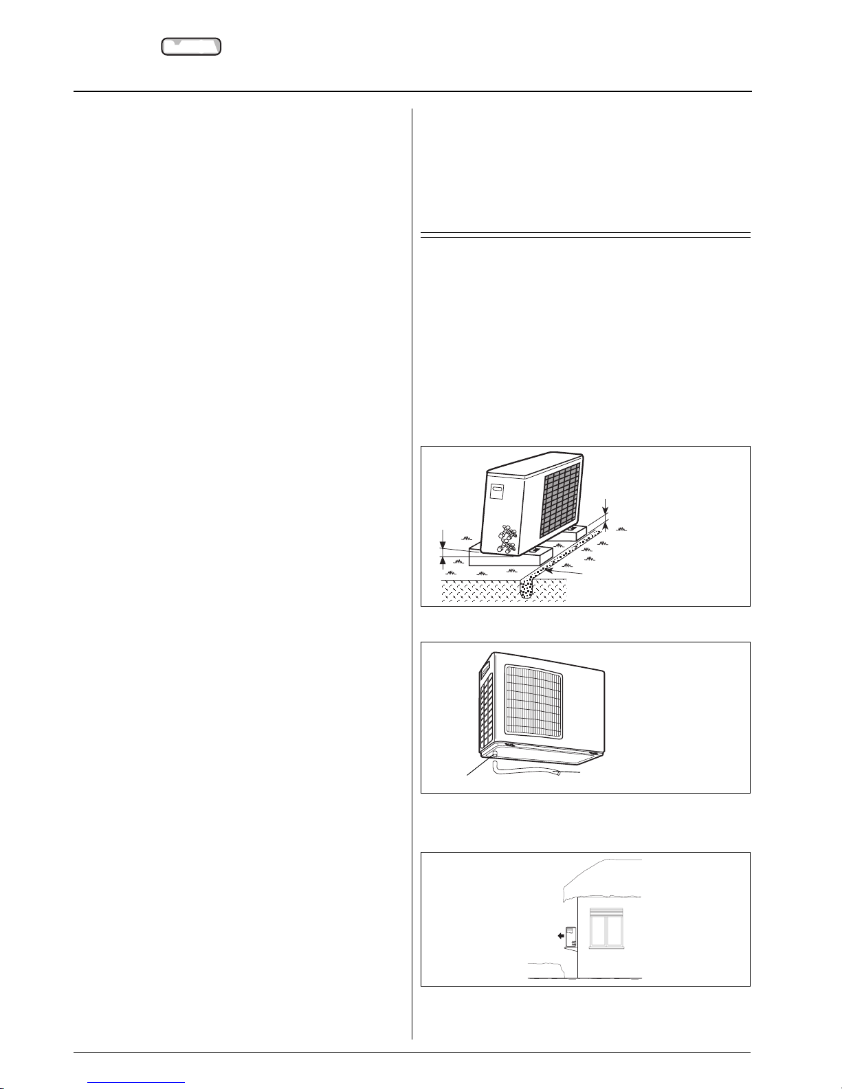
• For heat pump models, unit must be adequately raised above
floor surface.
• To drain the condensate water to a drain while operating in
heating mode, insert the drain fitting into the hole underneath on
the left of the basin and use a vinyl pipe with a 16 mm internal
diameter. It must not be used at temperatures lower than 0°C.
• If the unit is installed in areas where heavy snowfalls may
occur, it is necessary to raise its level at least 200 mm
above the usual snow level or alternatively use the outdoor
unit bracket kit.
General information
Unit installation
R-410A systems operate at higher pressures than standard
R-22 systems. Do not use R-22 service equipment or
components on R-410A equipment.
Read this instruction manual thoroughly before starting the
installation.
• This unit complies with low-voltage (EEC/73/23) and electro-
magnetic compatibility (EEC/89/336) directives.
• Check that the impedance of the mains power supply is in
conformance with the unit power input indicated in the
electric data table III, on page 11 (EN 61000-3-11).
• The installation must be carried out by a qualified installer.
• Follow all current national safety code requirements. In
particular ensure that a properly sized and connected ground
wire is in place.
• Check that voltage and frequency of the mains power supply are
those required; the available power must be adequate to operate
any other possible appliances connected to the same line.
Also ensure that national safety code requirements have been
followed for the mains supply circuit.
• The mains supply must be connected to the outdoor unit.
• Connect indoor and outdoor units with field-supplied copper
pipes by means of flare connections. Use insulated seamless
refrigeration grade pipe only, (Cu DHP type according to
ISO1337), degreased and deoxidized, suitable for operating
pressures of at least 4200 kPa and for burst pressure of at
least 20700 kPa. Under no circumstances must sanitary type
copper pipe be used.
• After installation thoroughly test the system operation and explain
all system functions to the owner.
• Leave this manual with the owner for consultation during future
periodic maintenance.
• Use this unit only for factory approved applications: the unit is
suitable for outdoor installation.
• This installation manual describes the installation procedures of
the outdoor unit of a residential split system consisting of units
manufactured by Carrier. Consult the Carrier stockist to check the
possibility of connecting your multisplit unit to indoor units other
than those foreseen by the manufacturer. Do not connect this unit
to any other manufacturer's indoor unit. Coupling units which have
different control systems, may cause irreversible damage and void
the warranty protection. The manufacturer declines any liability for
system malfunction resulting from unapproved coupling.
IMPORTANT:
During unit installation make first refrigerant connections and
then electrical connections. If the unit is uninstalled first
disconnect electrical cables, then refrigerant connections.
WARNING:
Disconnect the mains power supply switch before servicing
the system or handling any internal parts of the unit.
• The manufacturer declines any liability for damage resulting from
modifications or errors in the electrical or refrigerant connections.
• Failure to observe the installation instructions or use of the unit
under conditions other than those indicated in Table II “Operating
limits”, will immediately void the unit warranty.
• Failure to observe electric safety codes may cause a fire hazard in
case of short circuits.
• Inspect equipment for damage due to improper transportation or
handling: file an immediate claim with the shipping company.
Do not install or use damaged units.
• In case of any malfunctioning turn the unit off, disconnect the
mains power supply and contact a qualified service engineer.
• This equipment contains R-410A refrigerant, a substance that
does not deplete the ozone layer.
• All manufacturing and packaging materials used for your new
appliance are compatible with the environment and can be
recycled.
• Dispose of the packaging material in accordance with local
requirements.
100 mm min.
mm gradient
Gravel-filled trench.
Snow
Drain fitting
Vinyl pipe
Page 6
GB - 5
38VYM
R-410A
ENGLISH
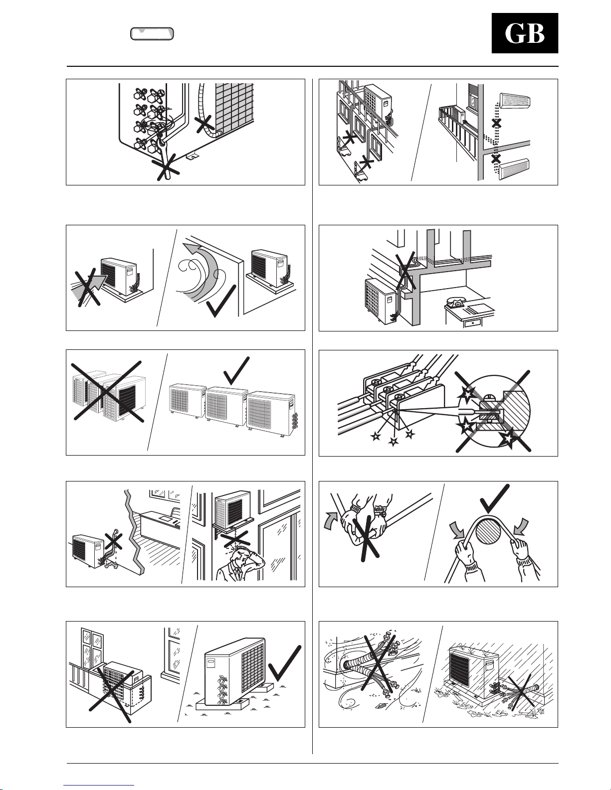
Excessive height difference between indoor and outdoor unit (see
Table I “Connections”). Excessive distance between indoor and
outdoor units. (see Table I “Connections”).
Unnecessary turns and bends in the connecting pipes.
Any slack in the electrical connections.
Flattening or kinking of refrigerant or condensate pipes.
Soiling of pipe ends.
Allowing piping to get wet before connection.
Disconnecting the refrigerant connections after installation - as this
will cause refrigerant leaks.
Connecting the condensate drain pipe to the outdoor unit.
Predominant head winds.
Multiple unit installation with units facing each other.
Insulating the connecting pipes only partially, which will cause dripping.
Dripping into passageways.
Any obstruction of the unit air outlet and intake or any obstacle that is too
close (see minimum clearances required). Installation on gr assy ground
or soft surfaces (in these cases a solid foundation must be included).
Warnings: av oid....
Page 7
38VYM
R-410A
GB - 6
Refrigerant connections
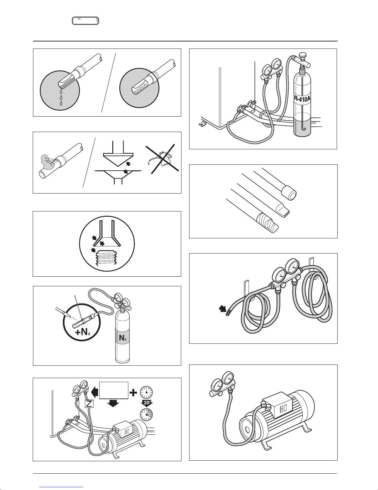
Charge liquid - no gas.
Protect copper tubes during storage.
Use tools designed for R-410A - higher pressure.
Keep inside clean.
2-stage vacuum pump. Replace oil regularly.
No moisture.
No dust.
No leak.
No mineral oil.
Neat.
Dry nitrogen brazing.
Vacuum.
Min.
– 100 kPa
(– 755 mmHg)
1/2” UNF (R-410A)
7/16” UNF (R-22)
Page 8
38VYM
R-410A
GB - 7
ENGLISH
Refrigerant connections
L
L
1
2
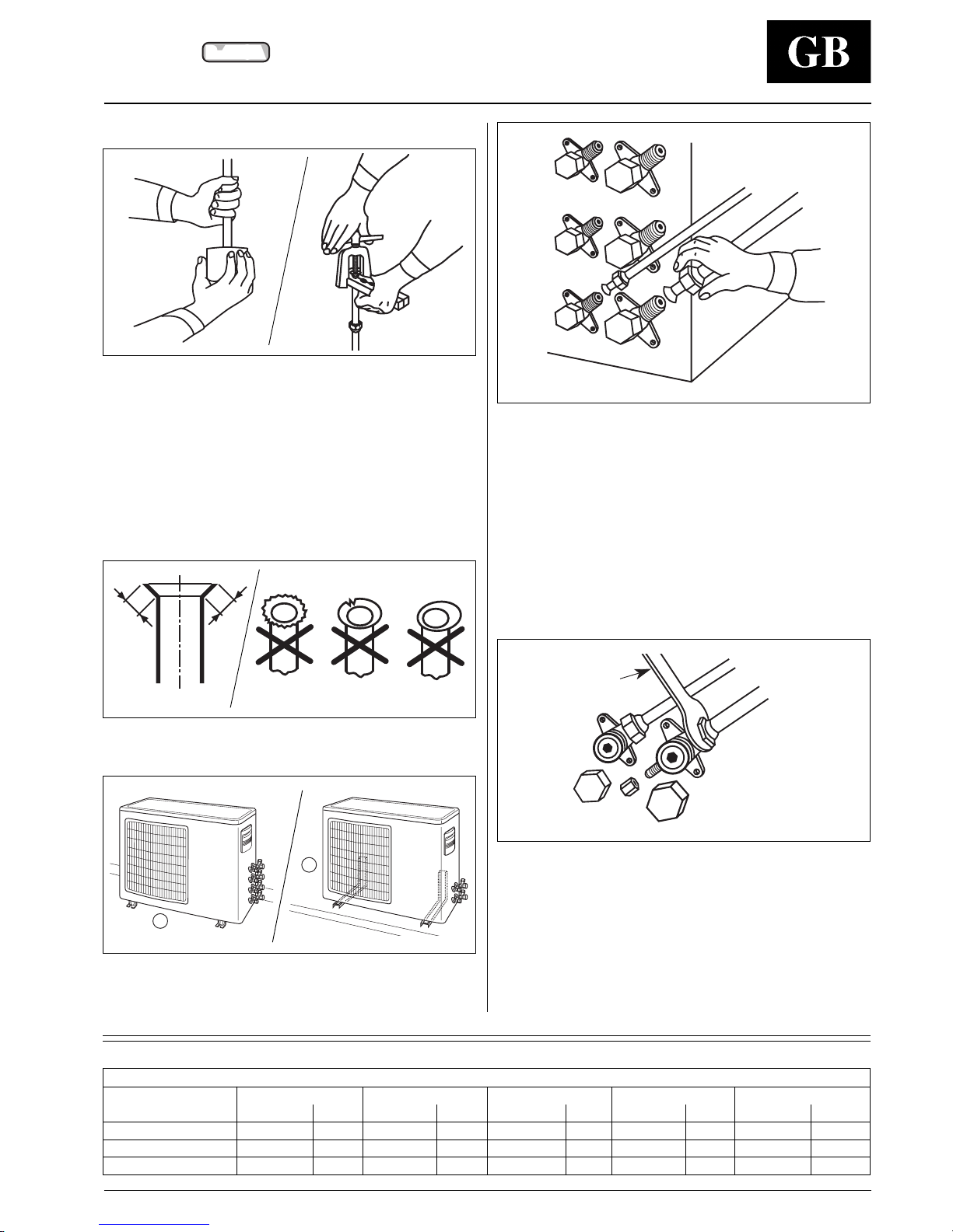
Flaring the ends of the tubing
Remove protective caps from copper tube ends.
Position tube end downward, cut the tube to the requested length
and remove the burrs with a reamer.
Do not leave the system open to the atmosphere any longer than
the minimum required for installation.
Oil in the compressor is extremely susceptible to moisture
absorption.
Always keep ends of tubing sealed during installation.
Remove flare nuts from the unit connections and place them on the
tube end.
Flare the tube with the flaring tool.
The flare end must not have any burrs or imperfections.
The length of the flared walls must be uniform.
The unit can be installed:
on the floor;
on the wall using the bracket kit.
Connect tubing in accordance with the limits shown on Table II
(Connections).
Finger-tighten the fitting several turns, then tighten it with a
wrench by applying the tightening torque indicated in the table.
Adjustable wrench
or torque wrench
Connection to unit
Insufficient tightening torque will cause gas leaks.
Overtightening the fittings will damage the tube flaring and
cause gas leaks.
• Make certain the refrigerant pipes and the electrical
connection lines between the indoor unit and the
outdoor unit have the same colours and reference codes
(
A1, A2, A3, A4
) using the special adhesive references
supplied.
Tightening torque
Valve
Flare nut Valve cap Pressure port cap Valve needle Pressure port
Wrench mm Nm Wrench mm Nm Wrench mm Nm Wrench mm Nm Wrench mm Nm
1/4” 17 18 23 20 18 16 - 18 Allen (hex.) 5 9 – 0.34
3/8” 22 42 23 20 18 16 - 18 Allen (hex.) 5 9 – 0.34
1/2” 26 55 29 40 18 16 - 18 Allen (hex.) 5 13 – 0.34
Page 9
38VYM
R-410A
GB - 8
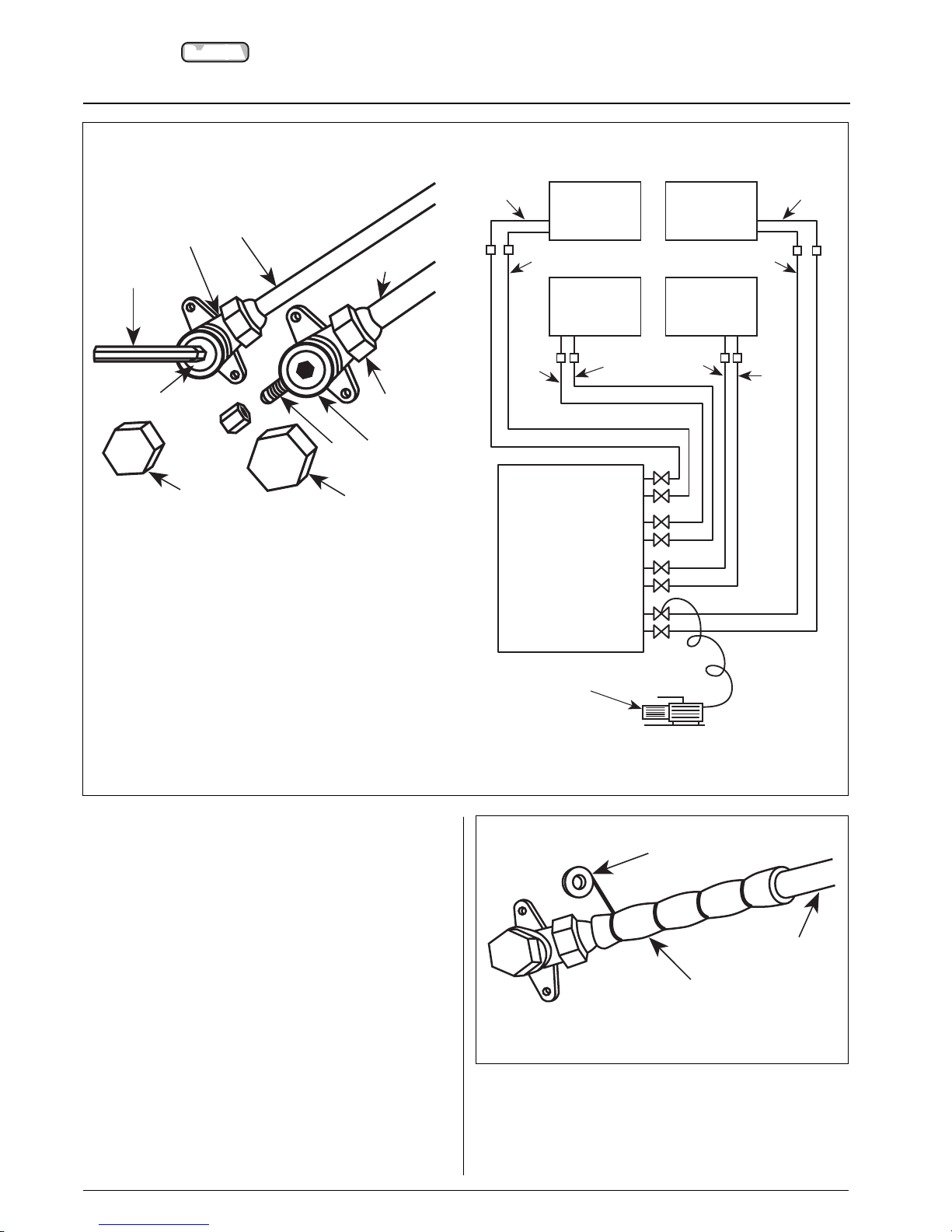
Three-way valve
Needle valve
Valve cap
Valve needle
Two-way valve
Allen (hex. head) wrench
Gas line (large diameter)
Liquid line (small diameter)
Service connection
Indoor unit
Outdoor unit
Vacuum pump
Air purging
USE ONLY A VACUUM PUMP T O PURGE AIR FR OM THE PIPING.
The air purging procedure must be performed for each of the
indoor units.
NEVER use the system compressor as a vacuum pump.
NEVER use the unit refrigerant gas to purge the connecting
pipes.
No additional refrigerant has been provided in the unit for this
purpose.
Remove the caps from the two and three-way valves.
Create a vacuum with a vacuum pump connected to the service
connection of the suction shut-off valve, as shown, keeping the
shut-off valves completely shut until a 50 Pa (0.5 mbar) vacuum
has been reached.
Now open the two-way valve for 3 sec., then quickly shut it to check
for possible leaks.
After the leak check, fully open the two and three-way valves.
Replace caps and check for leaks.
Once all connections have been completed, check for leaks by
using a leak detector designed for HFC refrigerants.
Finally wrap the valves and pipes with anti-condensate insulation
and tighten this with tape, without exerting too much pressure on
the insulation.
Repair and cover any possible cracks in the insulation.
Fix the pipes to the wall with hooks or conduits.
Refrigerant connections
Pipe
Pipe insulation
Fastening tape
Page 10
38VYM
R-410A
GB - 9
ENGLISH
Electrical connections
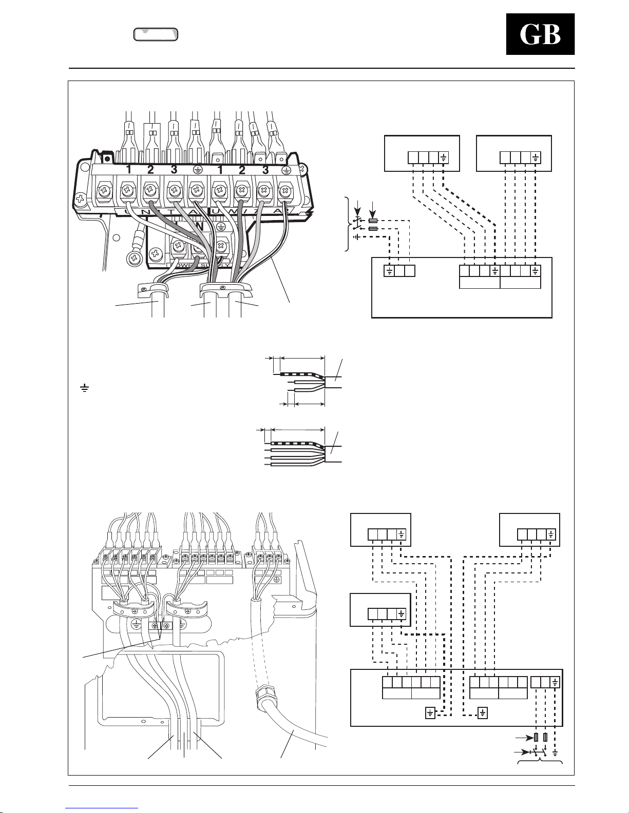
Unit 38VYM-18
10 80
50
10
10 40
System 38VYM-18
Unit 38VYM-28
System 38VYM-28
L N
UNIT A4
UNIT A3
UNIT A2
UNIT A1
32112312
3321321
L
N
A2 123
A1 123
230V ~ 50Hz
123 123
A1 A2
L
N
230V ~ 50Hz
A2 123
A1 123
123123
A1 A2
123123
A3 A4
A3 123
Terminal box legend
Earth.
L Live power supply.
N Neutral power supply.
1 Connection indoor/outdoor unit.
2 Connection indoor/outdoor unit.
3 Connection indoor/outdoor unit.
Indoor unit
Outdoor unit
Main switch
Time-delay fuse or circuit breaker
(see table III "Electrical data").
Mains supply connecting cable (field wiring).
Connecting cable, indoor-outdoor units A1.
Connecting cable, indoor-outdoor units A2.
Connecting cable, indoor-outdoor units A3.
Earth line.
Page 11
38VYM
R-410A
GB - 10
L N
UNIT A4
UNIT A3
UNIT A2
UNIT A1
32112312
3321321
Electrical connections
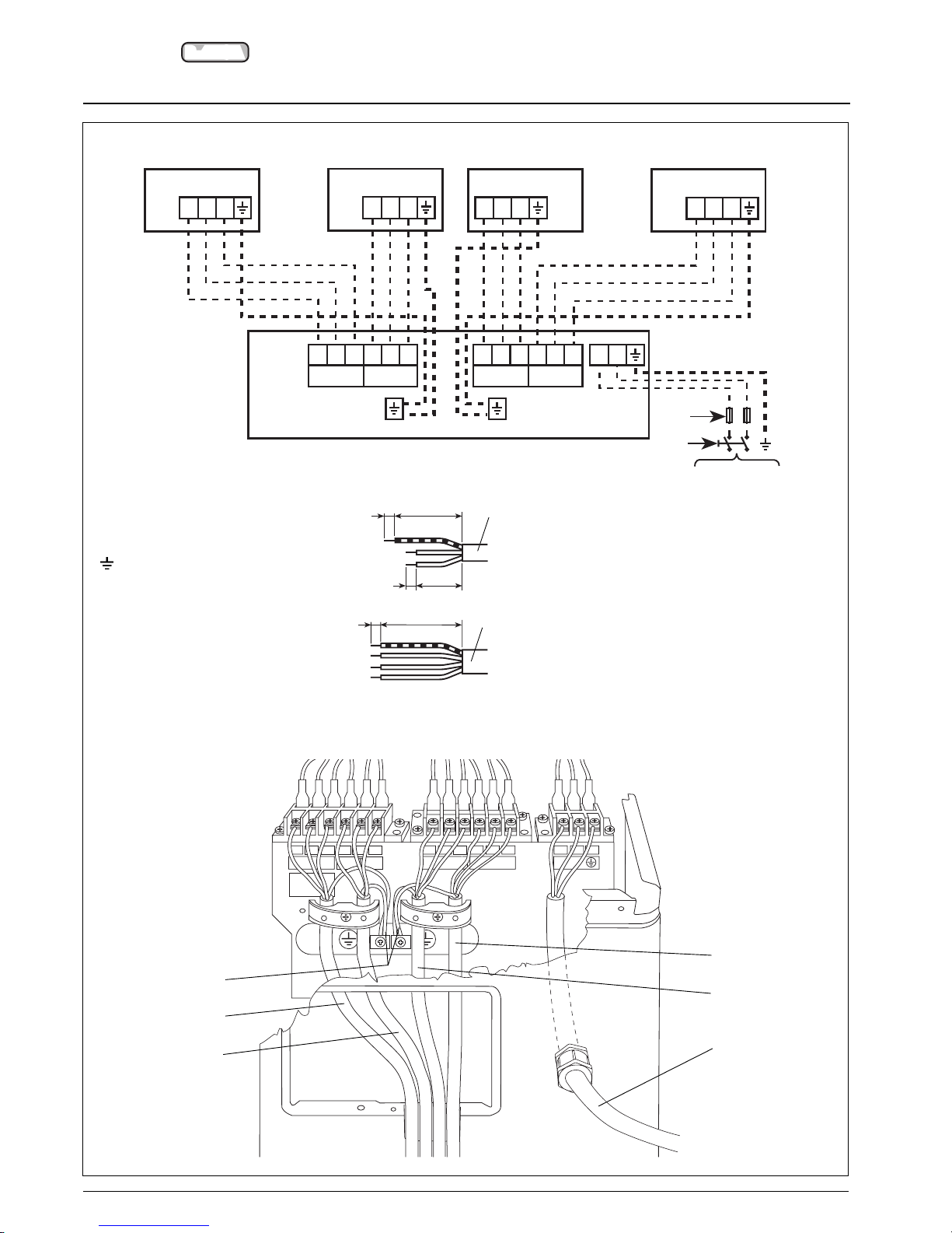
Unit 38VYM-32
System 38VYM-32
L
N
230V ~ 50Hz
123123
A1 A2
123123
A3 A4
A4 123
A2 123
A1 123
A3123
10 80
50
10
10 40
Terminal box legend
Earth.
L Live power supply.
N Neutral power supply.
1 Connection indoor/outdoor unit.
2 Connection indoor/outdoor unit.
3 Connection indoor/outdoor unit.
Indoor unit
Outdoor unit
Main switch
Time-delay fuse or circuit breaker
(see table III "Electrical data").
Mains supply connecting cable (field wiring).
Connecting cable, indoor-outdoor units A1.
Connecting cable, indoor-outdoor units A2.
Connecting cable, indoor-outdoor units A3.
Connecting cable, indoor-outdoor units A4.
Earth line.
Page 12
38VYM
R-410A
GB - 11
ENGLISH
Electrical connections
Heat pump
AW AW A W AW A
mm
2
38VYM-18
7.4 1700 8.6 1700 7.7 1750 11.5 2260 16 2.5
38VYM-28
9.5 2200 9.4 1840 10.8 2475 14.3 2750 25 2.5
38VYM-32
10.5 2410 9.6 1860 10.3 2330 14.5 2820 25 2.5
Table III: Electrical data
Heating
Cooling
Power input
(1-2)
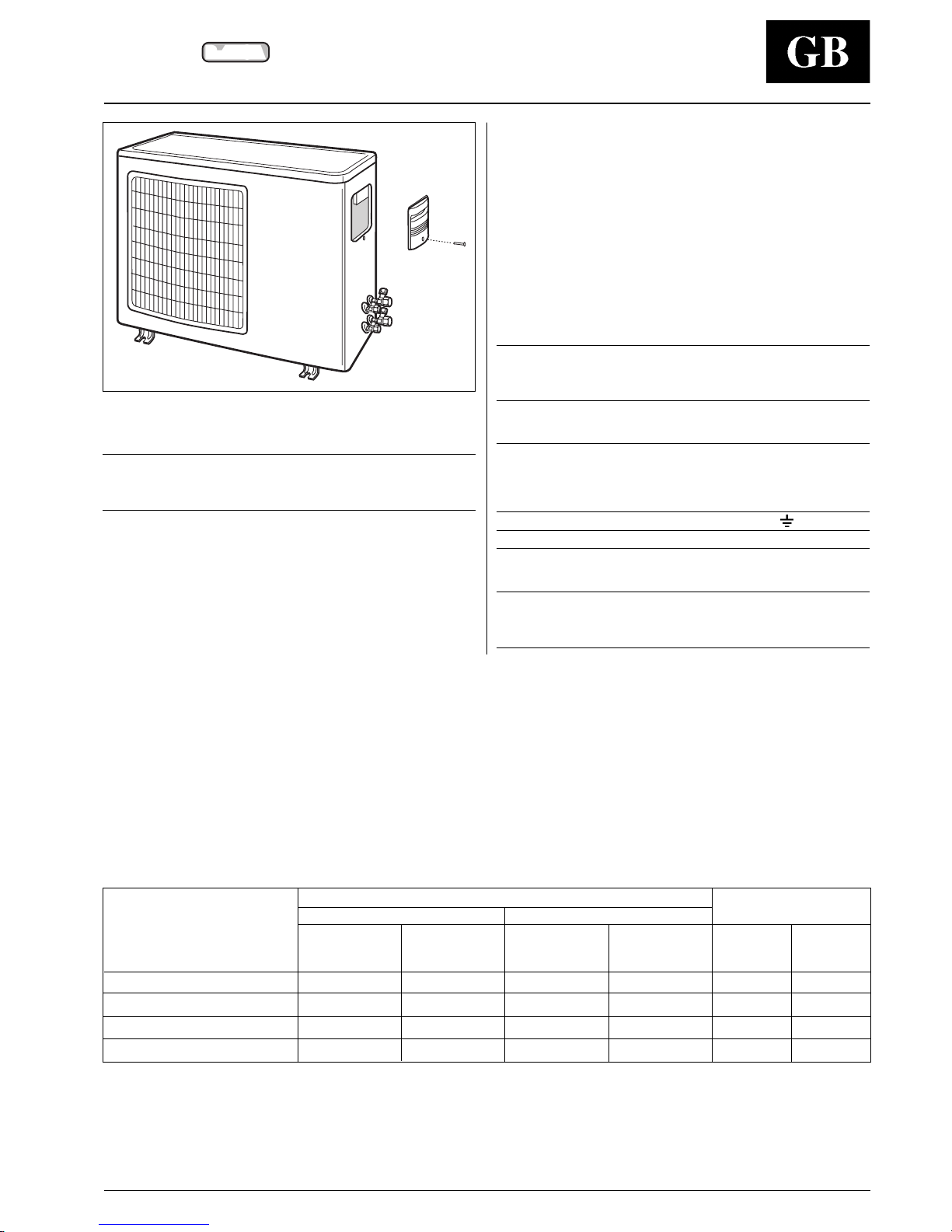
Remove control box co v er.
Connect the wires to the terminals according to the wiring diagram
and firmly tighten them.
IMPORTANT:
• Make ground connection prior to any other electrical
connections.
• Make electrical connections between units prior to proceeding to
mains supply unit connection.
• Before proceeding with the unit connection to the mains supply
locate live L and neutral N, then make connections as shown in
the wiring diagram.
• Ensure that mains supply connection is made through a switch
that disconnects all poles, with contact gap of a least 3 mm.
• The cables must be H07 RN-F type, for mains supply and for
interconnecting wires.
The above mentioned cables must have synthetic rubber
insulation with Neoprene coating, according to EN 60335-2-40
and HD277.S1 codes.
• The terminal block label refers to indoor unit A4.
This only refers to model 38VYM-32.
• Make certain the refrigerant pipes and the electrical
connection lines between the indoor unit and the
outdoor unit have the same colours and reference codes
(A1, A2, A3, A4) using the special adhesive references
supplied.
Note:
All field electrical connections are the responsibility of
the installer.
Connection wire minimum size
between indoor and outdoor units
mm
2
Model 1 2 3
18-28-32 1.0 1.0 1.0 1.0
Note:
After connections have been completed, replace control
box cover.
Main power
connections
(3-4)
Time-delay
fuse
gL type
Minimum
wire size
Nominal conditions
230V ~ 50Hz
indoor 27°C d.b. 19°C w.b.
outdoor 35°C d.b. 24°C w.b.
Peak conditions
198V ~ 50Hz
indoor 32°C d.b. 23°C w.b.
outdoor 43°C d.b. 32°C w.b.
Nominal conditions
230V ~ 50Hz
indoor 20°C d.b. 15°C w.b.
outdoor 7°C d.b. 6°C w.b.
Peak conditions
198V ~ 50Hz
indoor 27°C
outdoor 24°C d.b. 18°C w.b.
Notes:
Unit is suitable for outdoor installation.
(1)Data refers to the outdoor unit only.
(2)Data shown in the table, refers to the maximum number of connectable indoor units.
(3)The wire section refers to wires with a maximum length of 15 metres.
(4)The mains supply connecting cable must be H07 RN-F (or higher) type, with synthetic rubber insulation with Neoprene coating,
according to EN 60335-2-40 and HD277.S1 codes.
Page 13
38VYM
R-410A
GB - 12
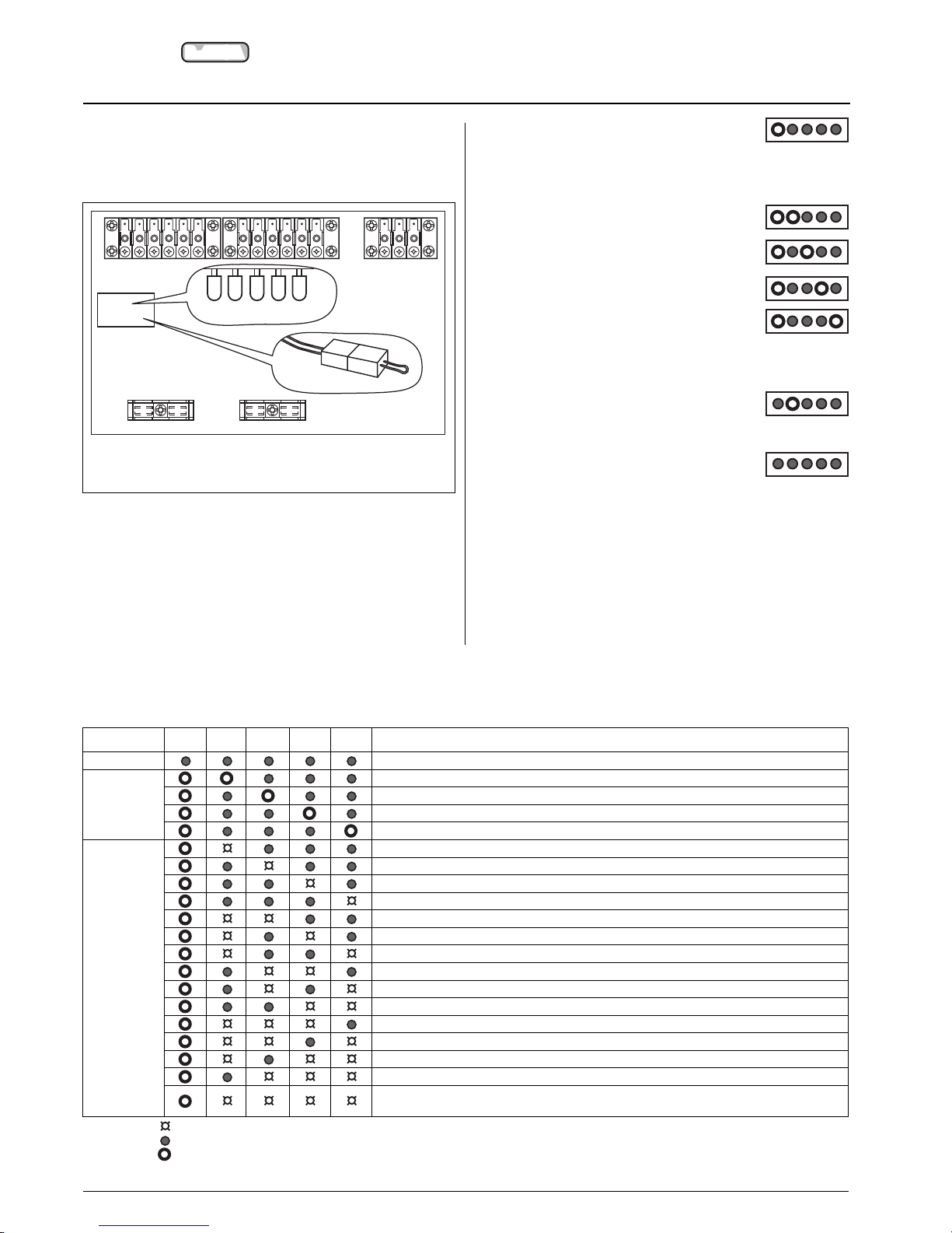
Incorrect wiring and piping procedure chec k
This procedure only applies to models 38VYM-28 and 38VYM-32.
The incorrect wiring/piping procedure check can be performed at an
ambient temperature of 5°C or more.
Sequence with electrical and refrigerant connections correctly
carried out:
• Position the red connector outside of terminal block zone.
• Switch the main power supply ON and start all indoor units in
cooling mode.
• Disconnect the red connector (incorrect wiring/piping test),
with compressor OFF.
• Start the test sequence for incorrect wiring/piping.
• The yellow LED flashes (D800).
• During the test for incorrect wiring/piping, the
compressor starts operating at a fixed frequency, the outdoor unit
fan operates normally, the indoor unit fans remain OFF.
• The yellow LED and red LED flash
(D800 and D801).
• The yellow LED and red LED flash
(D800 and D802).
• The yellow LED and red LED flash
(D800 and D803).
• The yellow LED and red LED flash
(D800 and D804).
• Normally the test procedure for incorrect
wiring/piping lasts from 3 to 15 minutes.
• When the test procedure is completed, the compressor and
outdoor unit fan stop operation, the red LED
(D801) flashes, while the yellow one (D800) is
OFF.
• If no incorrect wiring/piping has been found, system automatically
restarts and the red LED (D801) that was
flashing, turns OFF.
• Reconnect the red connector .
At the end of the test, if there is a fault code, the yellow LED
(D800) flashes and the red LEDs that indicate the defect remain ON
(see table).
The compressor does not start and the indoor unit fans operate in
fan only mode.
After the defect has been corrected, repeat the procedure and carry
out another check.
CHECK LED
LED
LED D800 D801 D802 D803 D804 Description
Normal operation (no fault)
Checking unit A1
Check
Checking unit A2
Checking unit A3
*
Checking unit A4
Kinking/clogging of pipe unit A1
Kinking/clogging of pipe unit A2
Kinking/clogging of pipe unit A3
*
Kinking/clogging of pipe unit A4
Incorrect wiring/piping or kinking/clogging of pipe unit A1, A2
Incorrect wiring/piping or kinking/clogging of pipe unit A1, A3
*
Incorrect wiring/piping or kinking/clogging of pipe unit A1, A4
Fault
Incorrect wiring/piping or kinking/clogging of pipe unit A2, A3
*
Incorrect wiring/piping or kinking/clogging of pipe unit A2, A4
*
Incorrect wiring/piping or kinking/clogging of pipe unit A3, A4
Incorrect wiring/piping of pipe unit A1, A2, A3
Incorrect wiring/piping of pipe unit A1, A2, A4
Incorrect wiring/piping of pipe unit A1, A3, A4
Incorrect wiring/piping of pipe unit A2, A3, A4
Incorrect wiring/piping of packed valve,
that keeps the circuit closed, unit A1, A2, A3, A4
Table IV: Check for incorrect wiring/piping
Legend:
LED ON
LED OFF
LED flashing
*
Only for 38VYM-32 model
Red LED (D803)
Red LED (D804)
Red connector
Yellow LED (D800)
Red LED (D801)
Red LED (D802)
Page 14
38VYM
R-410A
GB - 13
ENGLISH
T est procedure, Pump-down,
maintenance, guide f or the owner and accessories
Test procedure
• Energize the system by putting the main supply switch in the ON
position.
• The following procedure should be done in sequence for each
indoor unit (INDOOR UNIT A1, INDOOR UNIT A2, INDOOR UNIT
A3, INDOOR UNIT A4,). If multiple units are operating
simultaneously, you cannot carry out the check for cross
connection between refrigerant piping and control wiring or
incorrect system configuration.
• Operate the indoor unit A1 in cooling mode.
After five minutes in cooling mode check if the difference
between the temperatures at the indoor unit air inlet and outlet is
8°C or more.
• Check that the other indoor units A2, A3, A4 are not running.
• Verify that there is no sound of flowing refrigerant.
• If above conditions are not correct, check the refrigerant piping
connection and control wiring connection.
• Switch indoor unit A1 OFF using the remote control.
• Repeat the above procedure for indoor units A2, A3, A4.
IMPORTANT:
Test each indoor unit separately.
Pump-down
Pump-down is an operation intended to collect all the system
refrigerant in the outdoor unit.
This operation must be carried out before disconnecting the
refrigerant pipes in order to avoid refrigerant loss to the
atmosphere, if it becomes necessary to disconnect the
refrigerant connections for unit repair, removal or disposal; in
this case, after removal, the unit must be delivered to an
appropriate disposal centre or the original dealer.
Shut off the liquid valves with the Allen wrench.
Turn the indoor units ON in cooling with the fan operating at high
speed. After 2 minutes of operation, shut the suction valves with the
same Allen wrench.
Turn the system OFF and switch the mains supply OFF.
Disconnect the pipes.
After disconnection, protect valves and pipes ends from dust.
T able V: Accessories
Description Part number 38VYM 18 38VYM 28 38VYM 32
Wall bracket kit 38YL-900---001-40
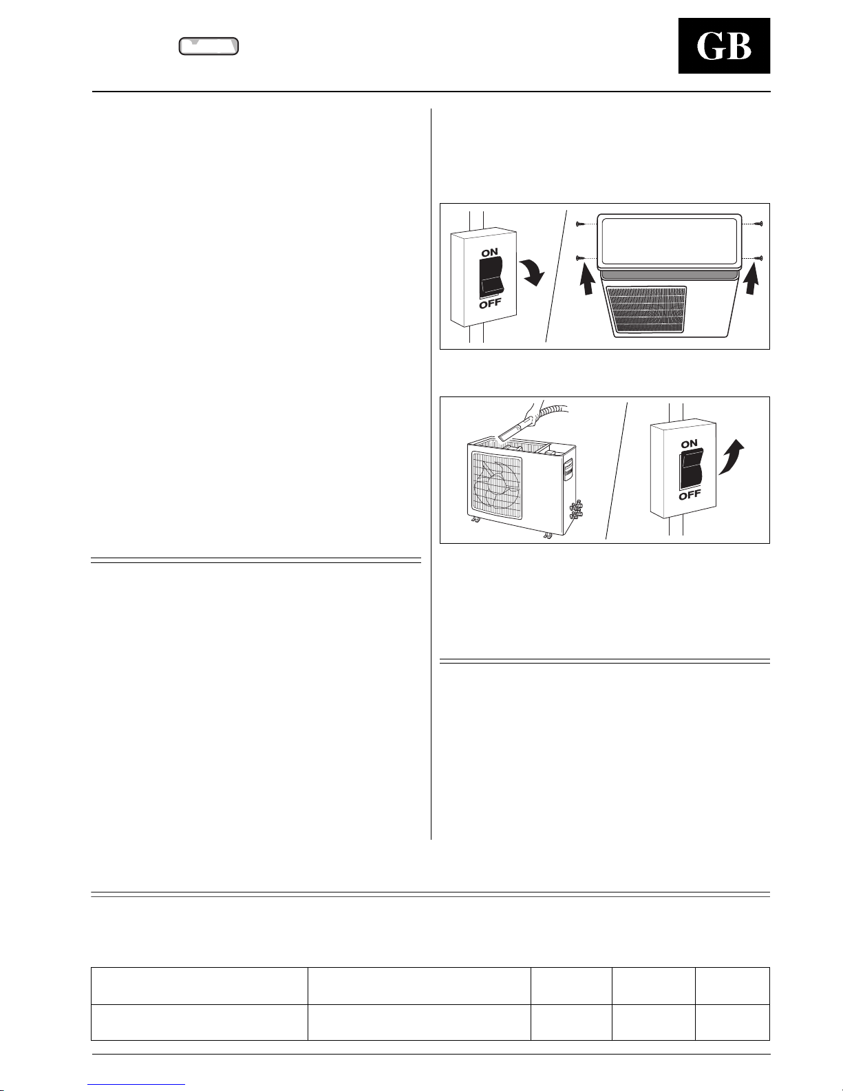
Maintenance
The following maintenance operations must be carried out by
qualified personnel.
Cleaning the coil
If necessary, proceed as follows for more careful cleaning of the
coil:
Switch the mains supply OFF.
Remove unit top cover by losening the fixing screws and lifting the
cover.
Carefully clean the coil with a vacuum cleaner from inside to
outside.
With the same vacuum cleaner, remove the dust from inside the fan
compartment and the fan blades. Avoid any damage to the blades
which may cause future vibrations and noise.
Replace the unit cover and tighten the screws.
Guide for the owner
When installation and tests are completed explain the Operation
and Maintenance Manual to the owner, with particular attention to
the main operating modes of the air conditioner, such as:
• Turning the unit on and off.
• Functions of the air conditioner.
• Removal and cleaning of the air filters.
Leave the two installation manuals for the indoor and outdoor units
with the owner for future use during maintenance operations or for
any other needs.
Page 15
L010125H16 - 0103
Via R. Sanzio, 9 - 20058 Villasanta (MI) Italy - Tel. 039/3636.1
The manufacturer reserves the right to change any product specifications without notice.
Order No. 13812-74M10, January 2003. Supersedes Order No. 13812-74M10, May 2002. Printed in Italy
 Loading...