

Carrier 38VNM218713, 38VNM327713, 38QUS036DS4, 38VNM436713, 42QHF009DS Installation Manual
...Page 1
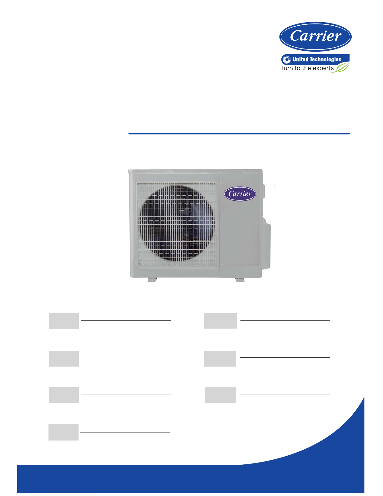
MULTI SYSTEM AIR CONDITIONER
INSTALLATION MANUAL
G B
ENGLISH
INSTALLATION MANUAL
I T
ITALIANO
MANUALE DI INSTALLAZIONE
F R
MANUEL D'INSTALLATION
D E
INSTALLATIONSHANDBUCH
DEUTSCH
E S
MANUAL DE INSTALACIÓN
N L
INSTALLATIEHANDLEIDING
NEDERLANDS
FRANÇAIS
ESPAÑOL
P L
POLSKI
INSTRUKCJA MONTAŻU
Page 2
The manufacturer reserves the right to change any product specifications without notice.
This product has been det ermined t o be in compl i ance with the Low Voltage Dire ct i ve (20 06/9 5/EC),
and t he Electromagnetic Compatibility Direct ive (2004/108/E C) of the European Union.
Correct Disposal of This Product
(Wast e Electrical & Electronic Equip men t )
(When using this air conditioner in European countries, the following guidance must be followed)
- T his marking shown on the product or its literature, indicates that waste electrical and eletrical equipment (WEEE as in
directive 2002/96/EC) should not be mixed with general household waste.
It is prohibited to dispose of this appliance in domestic household waste.
For disposal, there are several possibilities:
1. The municipality has established collection systems, where electronic waste can be disposed of at least free of charge to
the user.
2. When buying a new product, the retailer will take back the old product at least free of charge.
3. The manufacture will take back the old appliance for disposal at least free of charge to the user.
4. As old products contain valuable resources, they can be sold to scrap metal dealers.
Wild disposal of waste in forests and landscapes endangers your health when hazardous substances leak into the
ground-water and find their way into the food chain.
42QSM012DS*/ 42SVM-12
Type Model Name Rated Voltage & Hz
38QUS018DS2*/ 38VNM218713
42QSM018DS*/ 42SVM-18
42QTD009DS*/ 42CVS-09
Console Type
Indoor Unit
42QFA009DS*
38QUS027DS3*/ 38VNM327713
Duct Type
Indoor Unit
38QUS036DS4*/ 38VNM436713
220-240V ~ 50Hz
900x315x860
845x320x700
800x188x275
Dimension
Wall Mounted
Indoor Unit
920x635x210
570x570x260
700x600x210
42QHF009DS*/ 42HVF-09
990x345x965
GB-1
Outdoor Unit
800x188x27542QHF012DS*/ 42HVF-12
42QHF018DS*/ 42HVF-18 940x205x275
42QSM009DS*/ 42SVM-09 700x635x210
700x635x210
CassetteType
Indoor Unit
42QTD012DS*/ 42CVS-12
42QTD018DS*/ 42CVS-18
570x570x260
570x570x260
42QFA012DS*
42QFA018DS*
700x600x210
700x600x210
Page 3
CONTENTS
3
3
5
6
6
8
14
19
23
23
23
23
24
24
25
25
25
26
26
26
27
27
29
30
30
30
30
1. PREPARING FOR INSTALLATION ·······································································
1.1 Safety Percautions ··························································································
1.2 Indoor Combination ·························································································
2. INDOOR UNIT INSTALLATION ············································································
2.1 Wall Mounted Indoor ·······················································································
2.2 Duct Type Indoor ·····························································································
2.3 Cassette Type Indoor ·······················································································
2.4 Console Type Indoor ························································································
3. OUTDOOR UNIT INSTALLATION ······································································
3.1 Select The Installation Site ················································································
3.2 Outdoor Unit Mounting Dimensions ·····································································
3.3 Space Requirements For Outdoor Unit ·································································
3.4 Install The Outdoor Unit ················································································
3.5 Install The Drain Pipe For Outdoor Unit ······························································
4. REFRIGERANT PIPING WORK ··········································································
4.1 Flaring ·······································································································
4.2 Piping Work ·································································································
4.3 Refrigerant Pipe ··························································································
4.4 Air Evacuation ····························································································
4.5 Leakage Test ······························································································
5. WIRING ··········································································································
5.1 Wiring For Outdoor Unit ·················································································
5.2 Wiring For Indoor Unit ···················································································
6. FINAL CHECK AND TRAIL OPERATION ····························································
6.1 Final Check List ····························································································
6.2 Manual Operation ··························································································
6.3 Trail Operation ······························································································
7
GB-2
Page 4
GB-3
1. PREPARING FOR INSTALLATION
1.1 SAFETY PRECAUTIONS
WARNING
This symbol indicates the possibility of personnel injury or loss of life.
Installing, starting up, and servicing air-conditioning equipment can be hazardous due to system
ressures, electrical components, and equipment location (roofs, elevated structures, etc.).
Only trained, qualified installers and service engineers should install, start-up, and maintain this equipment.
When working on the equipment, observe precautions in the literature and on tags, stickers, and labels
attached to the equipment.
Follow all safety codes. Wear safety glasses and gloves. Keep quenching cloth and fire extinguisher
nearby when brazing. Use care in handing, rigging, and setting bulky equipment.
Read these instructions thoroughly and follow all warnings or cautions included in literature and attached to
the unit. Consult local building codes and National Electrical Code for special requirement.
Refrigerant gas is heavier than air and replaces oxygen. A massive leak could lead to oxygen
depletion, especially in basements, and an asphyxiation hazard could occur leading to serious
injury or death.
When the air conditioner is installed in a small room, provide appropriate measures to ensure that
the concentration of refrigerant leakage occur in the room does not exceed the critical level.
If the refrigerant gas leaks during installation, ventilate the area immediately.
Refrigerant gas may produce a toxic gas if it comes in contact with fire such as from a fan heater, stove or cooking device.
Exposure to this gas could cause severe injury or death.
Disconnect from power source before attempting any electrical work. Connect the connective cable
correctly.
Wrongly connecting may result damaged electric parts.
Use the specified cables for electrical connections and attach the wires firmly to the terminal block
connecting sections so that the external force is not exerted to the terminal.
Be sure to provide grounding.
Do not ground units to gas pipes, water pipes, lightning rods or telephone wires. Incomplete grounding could cause a severe
shock hazard resulting in injury or death.
Safely dispose of the packing materials.
Packing materials, such as nails and other matal or wooden parts, may cause stabs or other injuries. Tear apart and throw away
plastic pacaging bags so that children will not play with them. Children playing with plastic bags face the danger of suffocation.
Do not install unit near concentrations of combustible gas or gas vapors.
Be sure to use the supplied or exact specified installation parts.
Use of other parts may cause the unit to come to lose, water leakage, electrical shock, fire or equipment damage.
When installing or relocating the system, do not allow air or any substances other than the
specified refrigerant (R410A) to enter the refrigeration cycle.
Duct and Cassette type indoor is not accessible to the general public and intended to be
maintained by qualified service personnel and located at a level not less than 2.5m from floor.
Electrical work should be carried out in accordance with the installation manual and the national,
state and local electrical wiring codes.
Be sure to use a delicated power circuit. Never share the same power outlet with other appliance.
Page 5
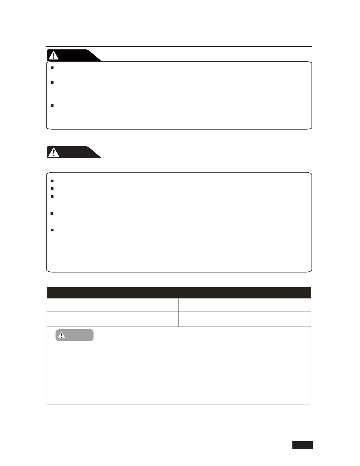
1. PREPARING FOR INSTALLATION
WARNING
CAUTION
This symbol indicates the possibility of property damage or serious consequences.
WARNING
Never modify this unit by removing any of the safety guards or bypassing any of the safety
interlock switches.
In order to avoid a hazard due to inadvertent resetting of the thermal cut-out, this appliance must
not be supplied through an external switching device, such as a timer, or connected to a circuit
that is regularly switched on and off by the utility.
Use the prescribed cables for electrical connection with insulation protected by insulation
sleeving having an appropriate temperature rating.
Unconformable cables can cause electric leak, anomalous heat prodcution or fire.
To avoid personal injury, be careful when handling parts with sharp edges.
Do not install the indoor or outdoor units in a location with special environmental conditions.
Do not install in a place that can amplify the noise level of the unit or where noise and discharged
air might disturb neighbors.
Perform the drainage/piping work securely according to the installation manual.
Improper drain piping may result in water leakage and property damage.
Do not instal the air conditioner in the following places.
-The place where there is mineral oil or arsenic acid.
-The place where corrosive gas (such as sulfurous acid gas) or combustible gas (such as thinner)
can accumulate or collect, or where volatile combustible substances are handled.
-The place there is equipment that generates electromagnetic fields or high frequencey harmonics.
This product contains fluorinated gases covered by t he Kyo to P rot oco l
Chemical Name of Gas
Global Wa rm i ng Potentia l (GWP) of Gas
R410A
2088
CAUTION
1. Paste the enclosed refrigerant label adjacent to the charging
and/or recovering location.
2. Clearly write the charged refrigerant quantity on the
refrigerant label using indelible ink.
3. Prevent emission of the contained fluorinated gas. Ensure
that the fluorinated gas is never vented to the atmosphere
during installation, service or disposal. When any leakage
of the contained fluorinated gas is detected, the leak shall
be stopped and repaired as soon as possible.
4. Only qualified service personnel are allowed to access and
service this product.
5. Any handling of the fluorinated gas in this product, such as
when moving the product or recharging the gas, shall comply
under (EC) Regulation No. 842/2006 on certain fluorinated
greenhouse gases and any relevant local legislation.
6. Contact dealers, installers, etc., for any questions.
72GB-4
Page 6
72GB-5
1. PREPARING FOR INSTALLATION
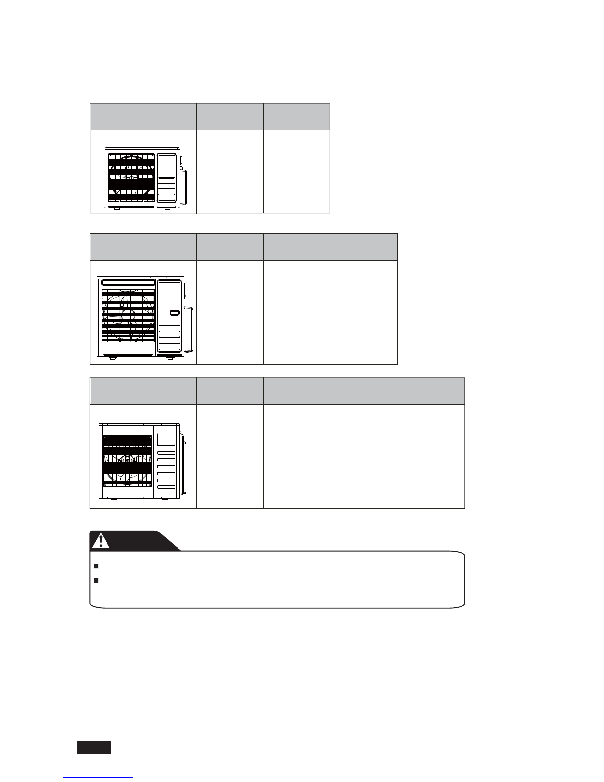
1.2 INDOOR COMBINATION
System 2
Single Indoor Two Indoors
09
12
18
09+09
09+12
12+12
System 3
Single Indoor Two Indoors
09
12
18
09+09
09+12
12+12
09+18
12+18
18+18
Three Indoors
09+09+09
09+09+12
09+12+12
09+09+18
12+12+12
System 4
Single Indoor Two Indoors
09
12
18
09+09
09+12
12+12
09+18
12+18
18+18
Three Indoors
09+09+09
09+09+02
09+12+12
09+09+08
09+12+18
Four Indoors
09+18+18
12+12+12
12+18+18
12+12+18
09+09+09+09
09+09+09+12
09+09+09+18
09+09+12+12
09+09+12+18
09+12+12+12
09+12+12+18
12+12+12+12
Total capacity of indoors should be less than 130% of capacity of outdoor.
When capacity of indoor combination is higher than capacity of outdoor, performance
may reduce if all indoors are working simultaneously .
CAUTION
18+09*
18+12*
[*] means two indoor unit shall not operate simultaneously due to performance reduction.
38QUS018DS2*/ 38VNM218713
38QUS027DS3*/ 38VNM327713
38QUS036DS4*/ 38VNM436713
Page 7
7
GB-6
2. INDOOR UNIT INSTALLATION
2.1 WALL MOUNTED INDOOR
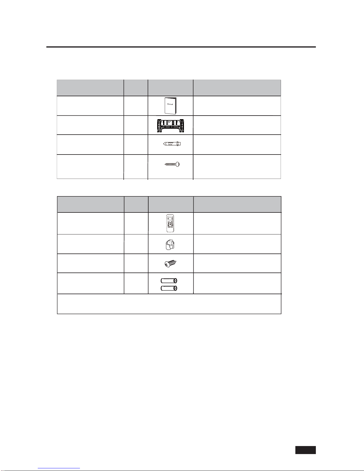
The following accessories are supplied with the indoor unit. The type and quantity may differ depending on the specifications.
1
1
5 or 8
Nam e of Accessories
Manual
Installation Plate
Hang the indoor unit
Q‘ty(pc)
Shape
Use
5 or 8
<User manual>,
<Remote controller manual> (or
<Wired controller manual>)
Anchor
Fix the installation plate.
Tapping screw B
Fix the installation plate
2.1.1 Accessories
1
Name of Accessories
Q‘ty(pc)
1
Shape Use
To remote
control the air conditioner
2
Battery
Tapped screw A
Remote controller holder
To hold the remote controller on the wall
For remote controller
2
Remote Controller
To fix the remote controller holder
Note: The accessories related to remote controller will be unavailable for the models with wired controller.
For wired controller accessories, please refer to attached manual of wired controller.
The following accessories are related to remote controller.
2.1.2 Installation site choosing
■ Where it is out of direct sunlight.
■ Where the airflow is not blocked.
■ Where an optimum air distribution is ensured.
■ Where the condensate can drain correctly and safely.
■ Install the indoor unit on a wall/ceiling that prevents vibration and is strong enough to hold the product weight.
■ Maintain sufficient clearance around the indoor unit for maintenance and servicing.
■ Where the air filter can be removed and cleaned easily.
■ Where the piping between the indoor and outdoor units is within the allowable limits.
■
Install the indoor unit 1m or more away from the TV or radio to prevent the screen from being distorted or noise from being generated.
■
Install the indoor unit as far away as possible from fluorescent and incandescent lights so that the remote control can be operated well.
■
Recommended installation height for the lowest moving part of indoor unit shall be at least 2.3m.
Page 8
7
GB-7
2. INDOOR UNIT INSTALLATION
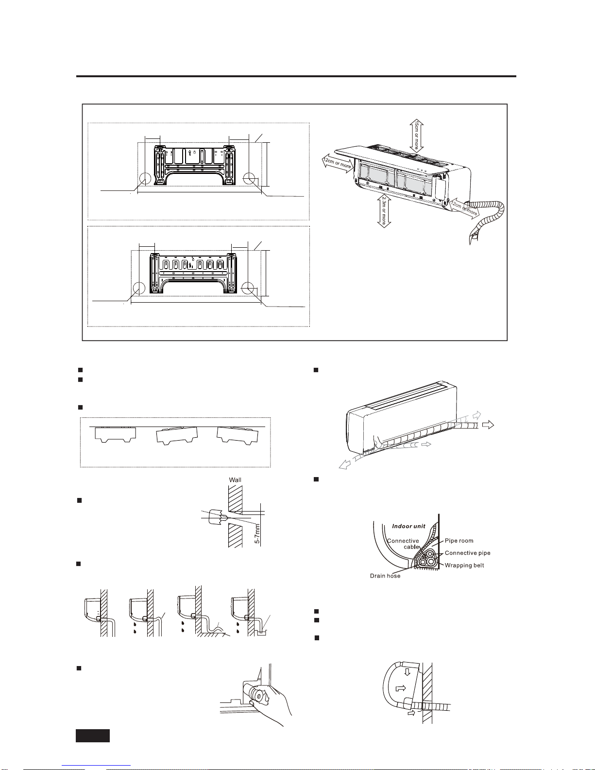
SPACE REQUIREMENT FOR INDOOR UNIT
Right rear side
refrigerant pipe
hole φ65
Left rear side
refrigerant
pipe hole φ65
Indoor unit outline
45
09/12:(A:800, B:275, C:100, D:95)
A
C
D
B
Right rear side
refrigerant pipe
hole φ65
Left rear side
refrigerant
pipe hole φ65
Indoor unit outline
45
A
C
D
B
18: (A:940, B:275, C:110, D:100)
The dimension of installation plate
Unit: mm
Note: Ensure the spaces indicated by arrows from
the wall, ceilling, fance or other obstacles.
Fix the mounting pate horizontally and level on the wall.
In case the wall is brick, concrete or similar material, drill
5mm diameter holes and insert anchors for the appropriate
mounting screws.
Secure the mounting plate with 5 or move B-type screws.
2.1.3 Install the mounting plate
X
O
X
Drill a 65mm hole on the wall
which is slightly tilted towards
the outsides.
2.1.4 Drill hole in the wall
Indoor Outdoor
The drain line must not have a trap anywhere in its length,
must pitch downwards, and must be insulated up to the
outside wall.
2.1.5 Drainage
Bend
S shape
Drain end
into water
O
X
X
X
The position of drain pipe interface can be
selected according to installation position.
During the adjustment of drain hose,
the unused interface should be sealed
by rubber plug.
Piping is possible in the rear, left, left rear right direction.
2.1.6 Wrap the piping
Right
Rear
Left rear
Left
For proper orientation of the refrigerant piping, electrical
cable and drain lines, refer to below Figure.
- Place the drain hose below the refrigerant piping.
- Make sure that the drain hose is not heaved or snaked.
Run refrigerant lines through hole in the wall.
Hang indoor unit on upper hook of mounting plate,then
push lower part of indoor unit up on wall to lower hook.
Move indoor unit from side to side, up and down to check
if it is hooked securely.
2.1.7 Hang the indoor unit
Page 9
7
GB-8
1
Nam e of Accessories
Q‘ty(pc)
1
Shape Use
To remote
control the air conditioner
2
Battery
Tapped screw
Remote controller holder
To hold the remote controller on the wall
N/A
For remote controller
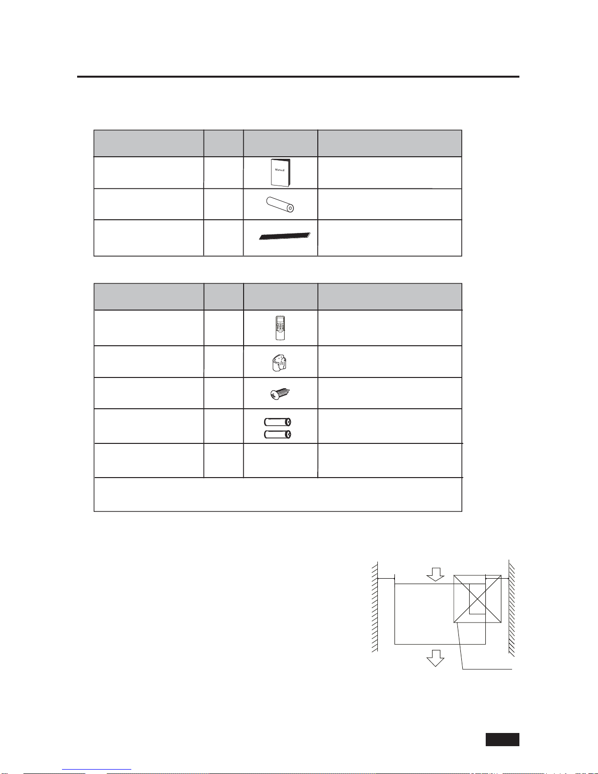
The following accessories are supplied with the unit. The type and quantity may differ depending on the specifications.
2
1
Note: Confirm that there is enough room
for installation and maintenance.
Remote Controller
To fix the remote controller holder
Connecting wire for display (2m)
Wire between display and control board.
Note: The accessories related to remote controller will be unavailable for the models with wired controller.
For wired controller accessories, please refer to attached manual of wired controller.
2
2
1
Nam e of Accessories
Manual
Pipe insulation material
Insulation
Q‘ty(pc)
Shape
Use
<User manual>,
<Remote controller manual> (or
<Wired controller manual>)
The following accessories are related to remote controller.
Inspection Opening
600mmX600mm
300mm or more
200mm or more
Seal sponge
For changing of air intake direction.
2. INDOOR UNIT INSTALLATION
2.2 DUCT TYPE INDOOR
2.2.1 Accessories
2.2.2 Installation site choosing
■ Where it is out of direct sunlight.
■ Where the airflow is not blocked.
■ Where an optimum air distribution is ensured.
■ Where the condensate can drain correctly and safely.
■ Install the indoor unit on a wall/ceiling that prevents vibration and is strong
enough to hold the product weight.
■
Maintain sufficient clearance around indoor unit for maintenance and servicing.
■ Where the air filter can be removed and cleaned easily.
■
Where the piping between the indoor & outdoor units is within the allowable limits.
■
Install the indoor unit 1m or more away from the TV or radio to prevent the
screen from being distorted or noise from being generated.
■
Install the indoor unit as far away as possible from fluorescent and incandescent
lights so that the remote control can be operated well.
Page 10
7
GB-9
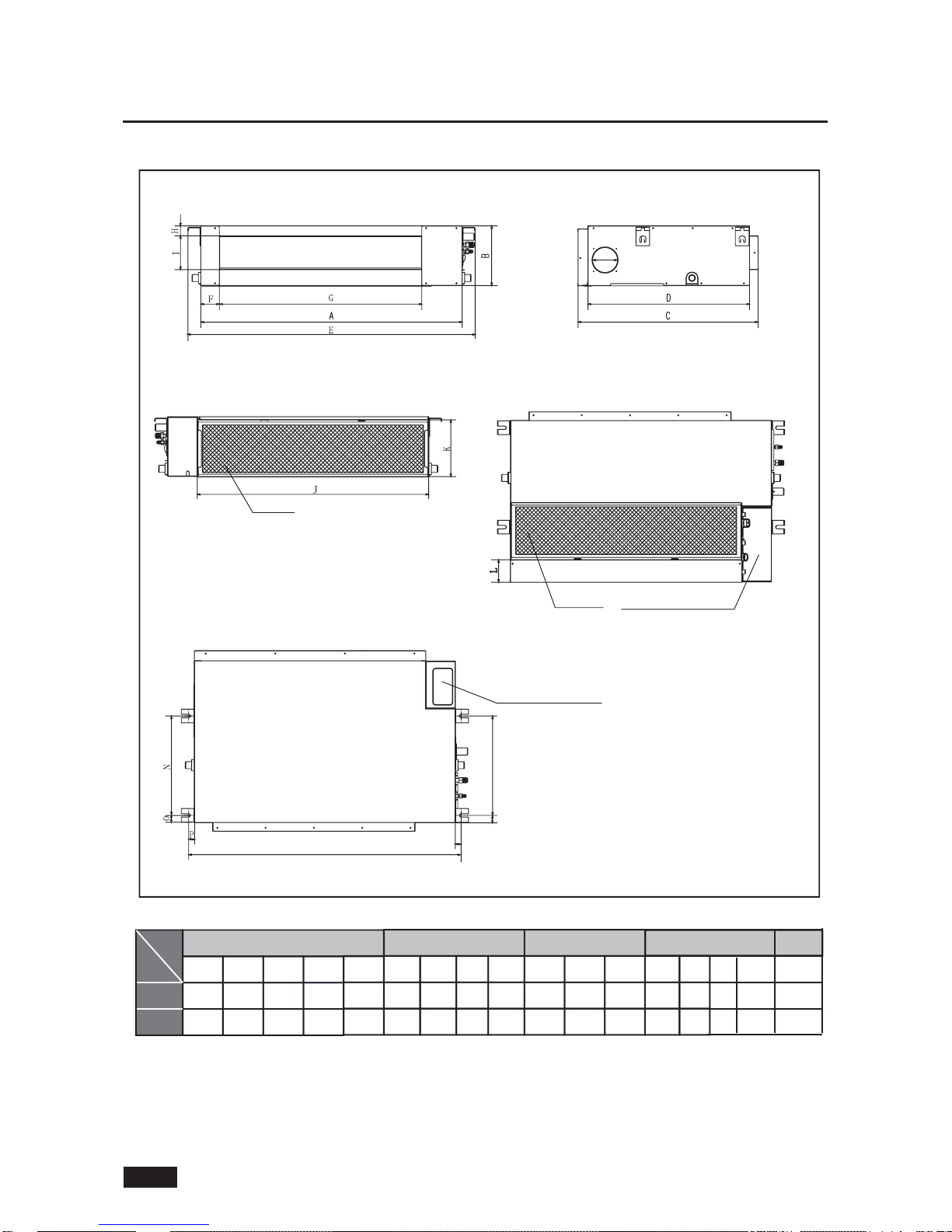
SPACE REQUIREMENT FOR INDOOR UNIT
Air filter
Air filter
Electric control cabinet
Electric control cabinet
The size of Outline dimension and air outlet opening
The size of air return opening
The size of descensional ventilation opening
The size of mounted lug
Unit: mm
T
M
P
N
O
Air outlet opening size
Air return opening size
Size of mounted hook
New air
inlet
Outline dimension
920 210 635 570
65 713 35 119 815 200 80 960 350
ABCDEFGHIJKLM
18
N
O
26
20
26
20
700 210 635 570
65 493 35 119 595 200 80 740 350
09/12
1010
790
P
Φ90
Φ90
T
Model
2. INDOOR UNIT INSTALLATION
Page 11
7
GB-10
2. INDOOR UNIT INSTALLATION
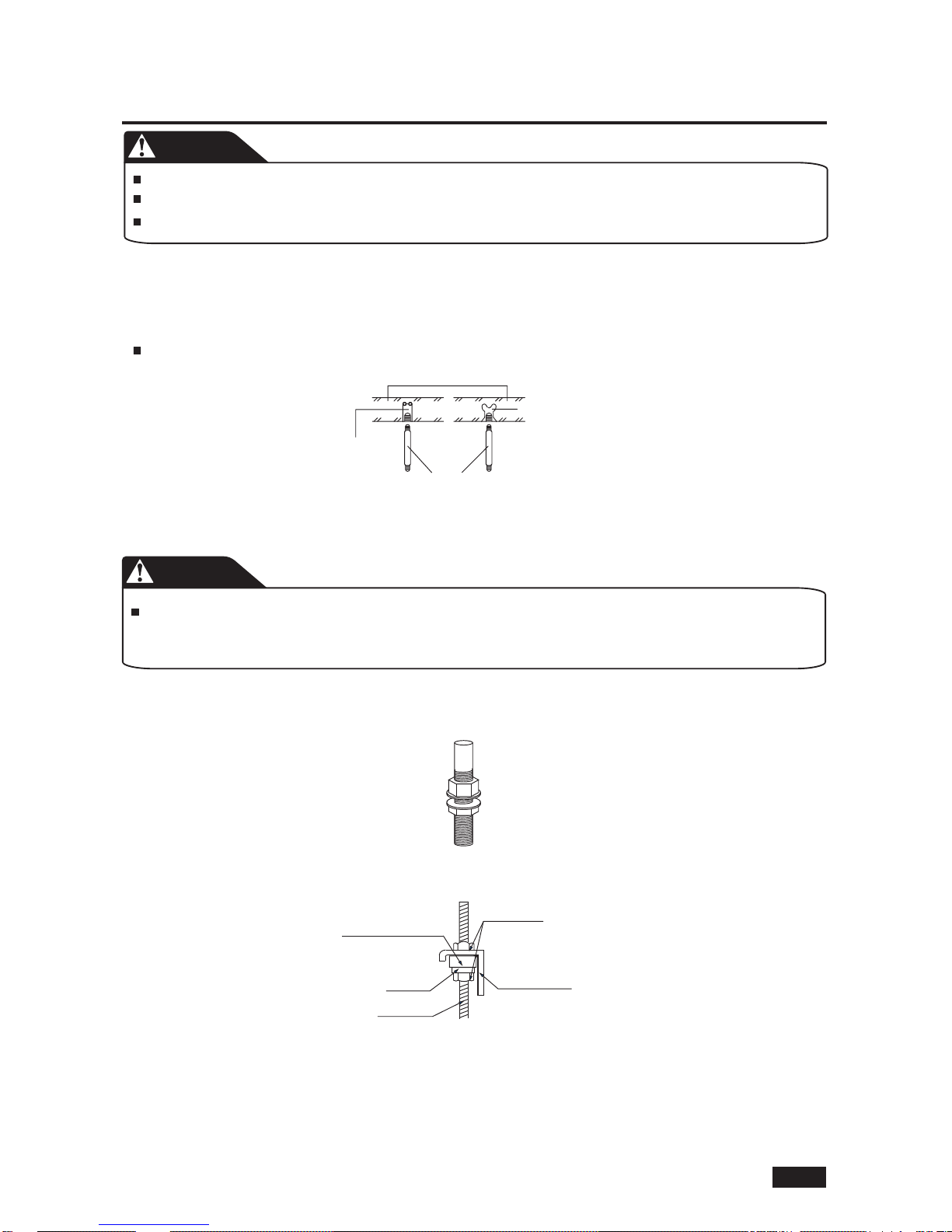
2.2.3.1 Mark the spots on the ceiling where you want to install the indoor unit.
2.2.3.2 Drill holes at the marking spots and then insert bolt anchors. Use existing ceiling supports or construct a suitable support.
NOTE
Use a hole-in-anchor, sunken insert for existing ceilings.
2.2.3.3 Install the suspension bolts (use W3/8 or M10 suspension bolts, 4 pieces) depending on the ceiling type.
2.2.3 Install the supension bolts
2.2.4.2 Hang the indoor unit to the suspension bolts between two nuts.
2.2.4.3 Screw the nuts to suspend the unit
2.2.4.4 Adjust level of the unit by using level vial for all four sides.
It is recommended to install the Y joint before installing the indoor unit
When moving the unit during or after unpacking, make sure to lift by holding its hooks.
Do not exert any pressure on other parts, especially the refrigerant piping, drain piping and flange parts.
CAUTION
2.2.4 Hanging the indoor unit
2.2.4.1 Screw double nuts to each suspension bolts making space for hanging the indoor unit.
Screw nut
Washer
Hanging
screw bolt
Overhang part
Shockproof cushion
Concrete
Suspension bolt(
3/8”
or M10)-field supply
Hole in anchor
Hole in plug
Insert
Ensure that the ceiling is strong enough to bear the weight of the unit. Before hanging the unit, test the
strength of each attached suspension bolt. It might be necessary to reinforce the ceiling frame to
prevent shaking. Consult an architect or carpenter for details
CAUTION
Page 12
7
GB-11
2. INDOOR UNIT INSTALLATION
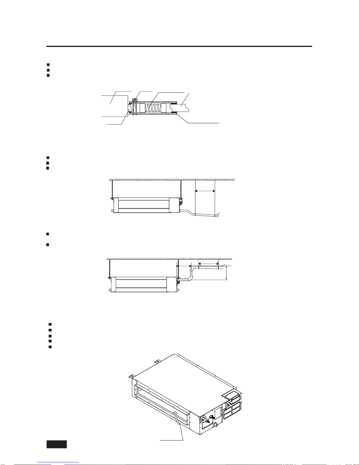
2.2.5 Install the drain pipe
Pipe clamp
Indoor unit
Flexible hose
Drain hose connection port
(O.D.:Φ25)
PVC water pipe
PVC adhesive
2.2.5.1 Drainpipe connection
For unit without the drain pump
Install horizontal drainpipe with a slope of 1/100 or more and fix it by hanger space 1.0~1.5m.
Install U-trap at the end of the drainpipe to prevent a nasty smell to reach the indoor unit.
Do not install the drainpipe to upward position. It may cause water flow back to the unit.
Lean over 1/100
1.0-1.5m
For unit with the drain pump
The drain pipe should be install within 200mm from the flexible hose and then install horizontal drainpipe with a slope of 1/00 or more
and fix it by hanger space of 1.0~1.5m.
The flexible hose should not be installed upward position; it may cause water flow back to the indoor unit.
Lean over 1/100
<200mm
1.0-1.5m
Max. 550mm
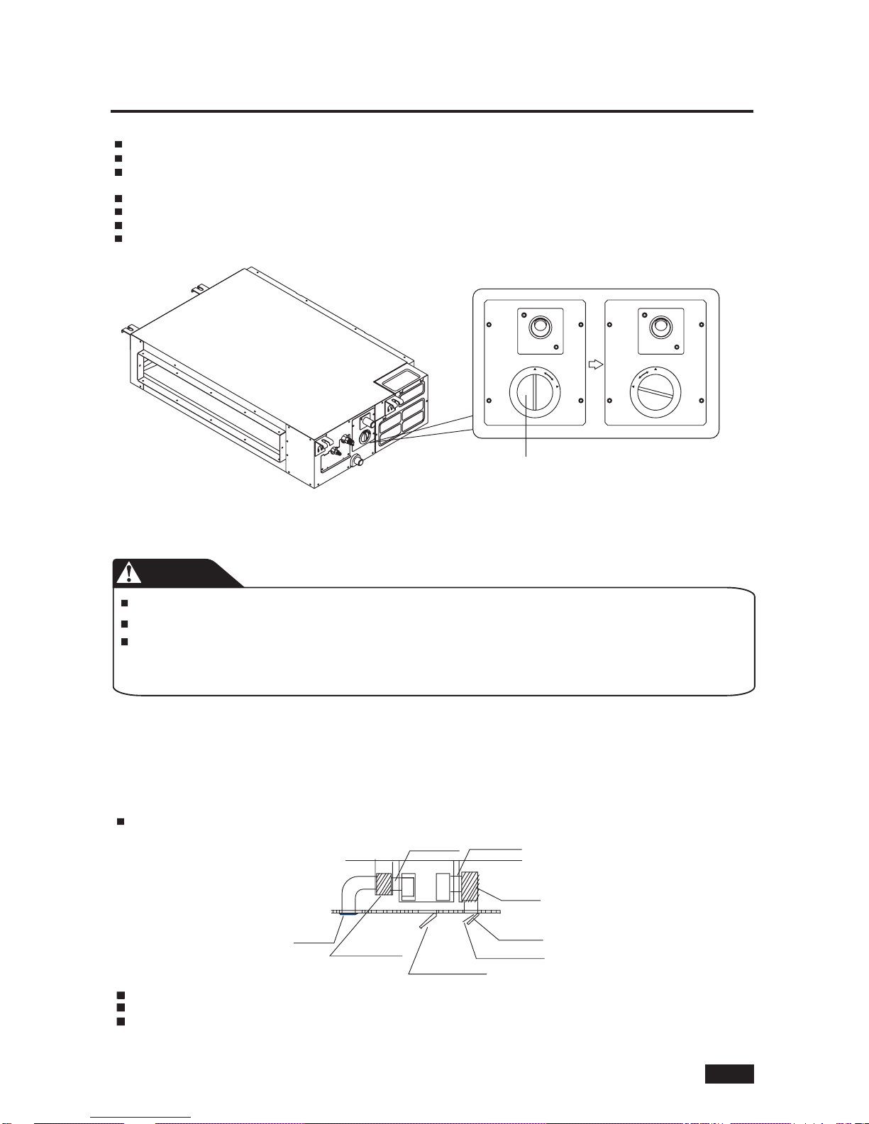
2.2.5.2 Drainage test
Unit without Pump
Conduct the drainage test before making the duct connection
Gradually insert about 2 liters of water into the drain pan indoor unit with stow tube.
Check and confirm the water flows out through the drain hose.
Check the drain water drops at the end of the drain pipe.
Make sure there is no water leak at the drainage
Stow tube
Unit without pump
Remove the cover of the drain hose connection port
Insert the flexible hose (field supply,I.D.:
Φ25
) to the drain hose port. Fix it to the indoor unit with pipe clamp (field supply) securely.
Install the flexible hose to the PVC water pipe securely with PVC adhesive. Wrap the drain hose with the insulation materials.
Page 13
7
GB-12
2. INDOOR UNIT INSTALLATION
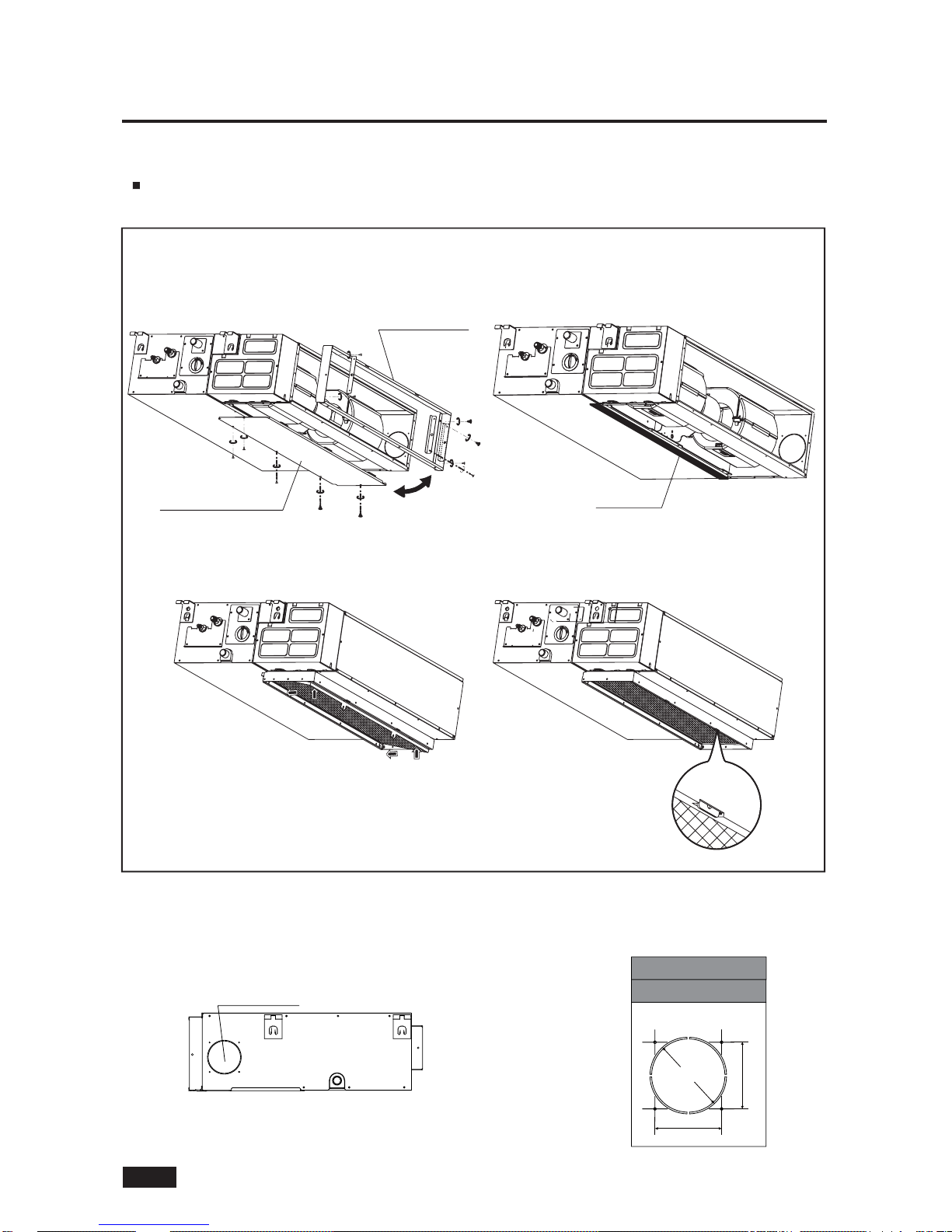
2.2.6 Install the duct
NOTE
Air inlet and air outlet should be apart far enough to ensure the performance of the unit.
When attaching a duct to the intake side, be sure also to attach an air filter (field supply)
Be sure to insulate the duct to prevent condensation from forming
Refer to the technical documentation for fan performance curve.
Canvas tie-in Canvas tie-in
Air outlet
Isolation booth
Isolation booth
Inspection opening
Air inlet
Air filter
Cover
Use the hanger rods to install the connecting duct instead of loading it directly onto the indoor unit.
Use nonflammable canvas tie-in to prevent vibration.
If external resistance is too high (due to long extension of duct, for example), the air flow volume may
drop too low at each air outlet. Consult qualified engineer to increase the fan speed to increase the static
pressure corresponding to external resistance.
Unit with Pump
Open the cover of water supply intake by turning and pulling the cover.
Gradually insert about 2 liters of water into the indoor unit with stow tube.
Operate the unit under COOLING mode and check a drain pump pumping (a time lag of 1 minute is allowed before water flowing
out depending on the length of the drain pipe).
Check and confirm the water flows out through the drain hose.
Check the drain water drops at the end of the drain pipe.
Make sure there is no water leak at the drainage
Reassemble the cover of water supply intake.
C
L
O
S
E
D
O
P
E
N
C
L
O
S
E
D
O
P
EN
Water supply intake
Unit with pump
CAUTION
Connect the duct supplied in the field.
2.2.6.1 Attach the duct and intake-side/outlet-side flange (field supply)
2.2.6.2 Connect the flange to the main unit with screws
2.2.6.3 Wrap the flange and duct connection area with aluminum tape or something similar to prevent air escaping.
Page 14
7
GB-13
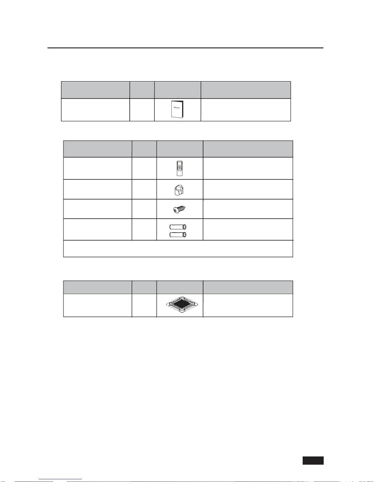
1.
Remove the air filter from the flange (two locations).
Remove the flange from the rear side.
Remove the ventilation panel from the bottom side.
2.
Attach the seal sponge at the place showing in the following
diagram.
Reinstall the removed flange at the bottom and reinstall the
removed the ventilation panel at the rear side.
3.
Attach the air filter to the flange in the manner shown in the diagram.
Flange
Ventilation panel
Seal sponge
2.2.7 Change the air ventilation direction (Alternative: Rear or Bottom)
NOTE
For standard unit, air intakes from rear side. Air intake direction can be modify at site from rear side to
bottom side following the process in below.
2.2.8 Install fresh air duct
All the indoor units reserve the hole to joint the fresh air pipe. The hole size as following:
Duct joint for fresh air
80mm
80mm
Ø90mm
MODLE
09~18
2. INDOOR UNIT INSTALLATION
Page 15
7
GB-14
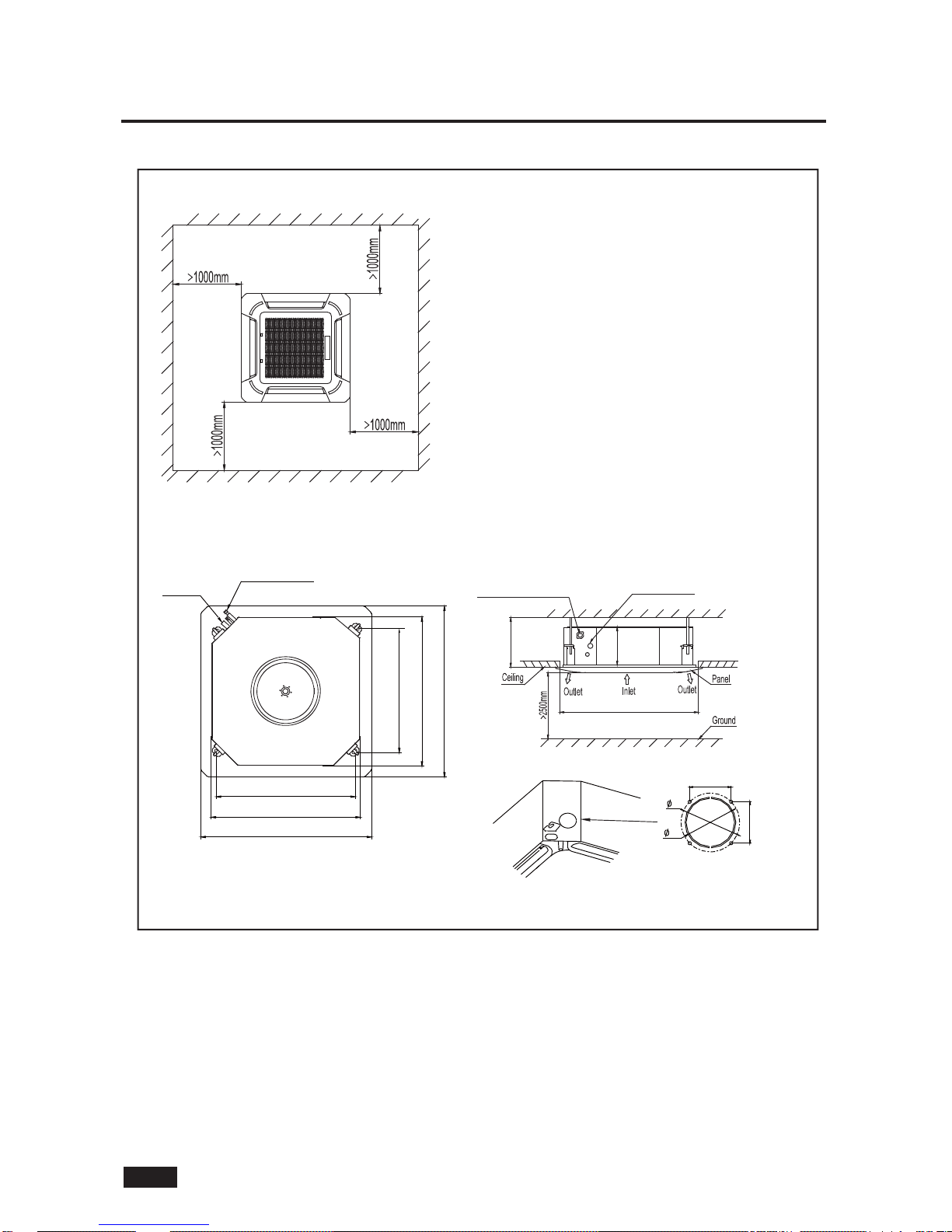
The following accessories are supplied with the indoor unit. The type and quantity may differ depending on the specifications.
2
Nam e of Accessories
Manual
Q‘ty(pc)
Shape
Use
<User manual>,
<Remote controller manual> (or
<Wired controller manual>)
2. INDOOR UNIT INSTALLATION
2.3 CASSETTE TYPE INDOOR
2.3.1 Accessories
1
Nam e of Accessories
Q‘ty(pc)
1
Shape Use
To remote
control the air conditioner
2
Battery
Tapped screw
Remote controller holder
To hold the remote controller on the wall
For remote controller
2
Remote Controller
To fix the remote controller holder
Note: The accessories related to remote controller will be unavailable for the models with wired
controller. For wired controller accessories, please refer to attached manual of wired controller.
The following accessories are related to remote controller.
Separate packed parts
Nam e of Accessories
Q‘ty(pc)
1
Shape Use
Panel
/
2.3.2 Installation site choosing
■ Where it is out of direct sunlight.
■ Where the airflow is not blocked.
■ Where an optimum air distribution is ensured.
■ Where the condensate can drain correctly and safely.
■ Install the indoor unit on a wall/ceiling that prevents vibration and is strong enough to hold the product weight.
■
Maintain sufficient clearance around indoor unit for maintenance and servicing.
■ Where the air filter can be removed and cleaned easily.
■
Where the piping between the indoor & outdoor units is within the allowable limits.
■
Install the indoor unit 1m or more away from the TV or radio to prevent the screen from being distorted or noise from
being generated.
■
Install the indoor unit as far away as possible from fluorescent and incandescent lights so that the remote control can
be operated well.
Page 16
7
GB-15
SPACE REQUIREMENT FOR INDOOR UNIT
The size of Outline dimension
Unit: mm
2. INDOOR UNIT INSTALLATION
Clearance from the wall or other obstacles
Connecting port
of refrigerant pipe
Connecting port
of drain pipe
Connecting port
of drain pipe
Connecting port
of refrigerant pipe
523(Hook-location)
570(Body)
647(Panel)
545(Hook-location)
570(Body)
647(Panel)
600mm(Ceiling hole)
290mm
260mm
Fresh air intake (Ø 65)
106
106
75
65
Page 17
7
GB-16
2. INDOOR UNIT INSTALLATION
2.3.3.1 Mark the spots on the ceiling where you want to install the indoor unit.
2.3.3.2 Drill holes at the marking spots and then insert bolt anchors. Use existing ceiling supports or construct a suitable support.
NOTE
Use a hole-in-anchor, sunken insert for existing ceilings.
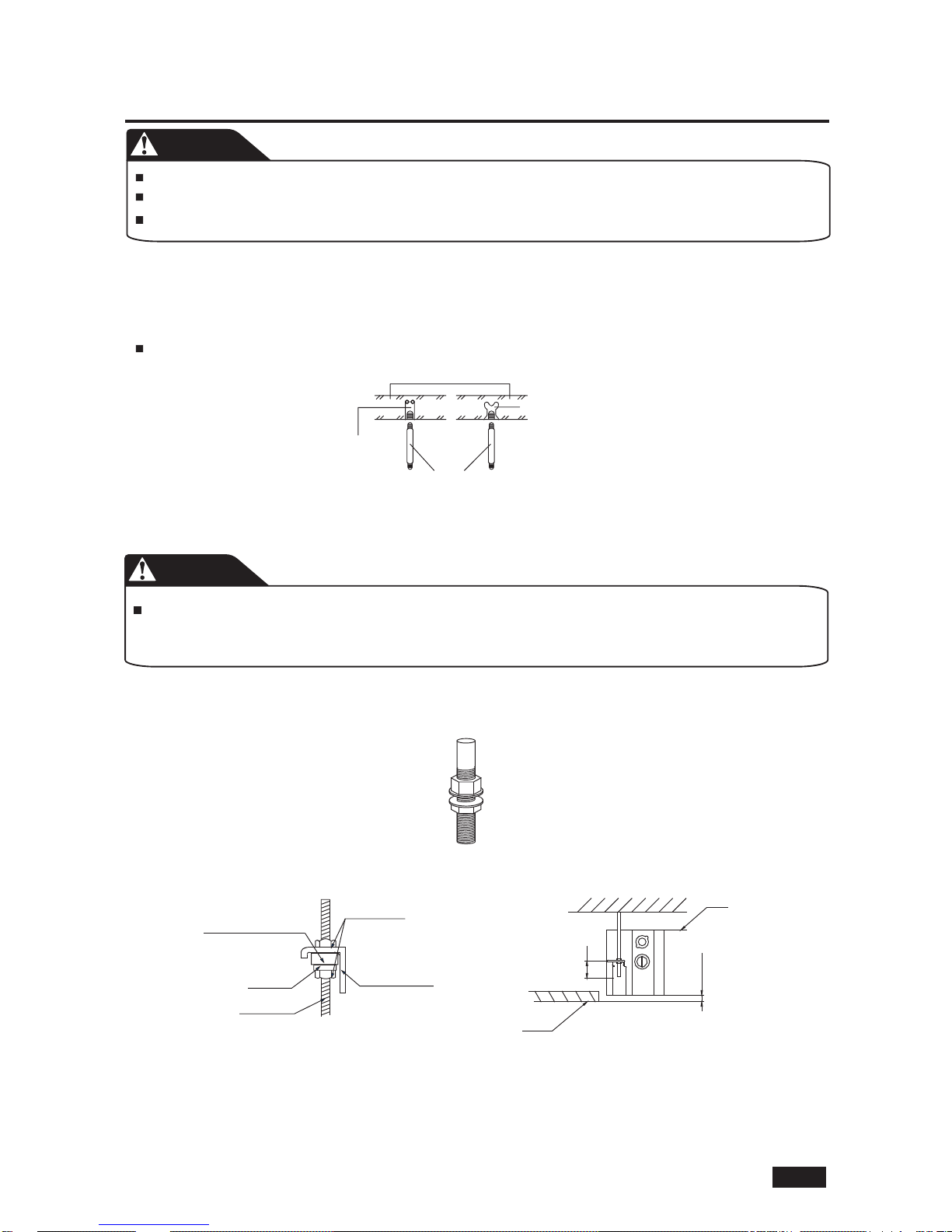
2.3.3.3 Install the suspension bolts (use W3/8 or M10 suspension bolts, 4 pieces) depending on the ceiling type.
2.3.3 Install the suspension bolts
2.3.4.2 Hang the indoor unit to the suspension bolts between two nuts.
2.3.4.3 Screw the nuts to suspend the unit. Check the lower side of indoor unit locates at position (10 to 12 mm) higher than the
lower surface of the ceiling. L is about half of the screw length of the installation hook.
2.3.4.4 Adjust level of the unit by using level vial to make sure horizontal level of the main body within ±1°.
It is recommended to install the Y joint before installing the indoor unit
When moving the unit during or after unpacking, make sure to lift by holding its hooks.
Do not exert any pressure on other parts, especially the refrigerant piping and drain piping.
CAUTION
2.3.4 Hanging the indoor unit
2.3.4.1 Screw double nuts to each suspension bolts making space for hanging the indoor unit.
Screw nut
Washer
Hanging
screw bolt
Overhang part
Shockproof cushion
Concrete
Suspension bolt(
3/8”
or M10)-field supply
Hole in anchor
Hole in plug
Insert
Ensure that the ceiling is strong enough to bear the weight of the unit. Before hanging the unit, test the
strength of each attached suspension bolt. It might be necessary to reinforce the ceiling frame to
prevent shaking. Consult an architect or carpenter for details
CAUTION
Ceiling
Body
10~12mm
L
Page 18
7
GB-177GB-16
2. INDOOR UNIT INSTALLATION
2.3.5 Install the drain pipe
Pipe clamp
Indoor unit
Flexible hose
Drain hose connection port
(O.D.:Φ25)
PVC water pipe
PVC adhesive
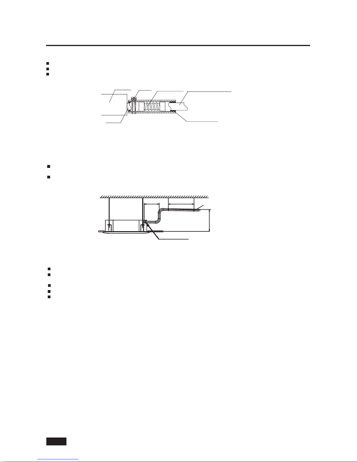
2.3.5.1 Drainpipe connection
Cassette unit is eqipped with the drain pump
The drain pipe should be install within 200mm from the flexible hose and then install horizontal drainpipe with a slope of 1/00 or
more and fix it by hanger space of 1.0~1.5m.
The flexible hose should not be installed upward position; it may cause water flow back to the indoor unit.
Lean over 1/100
1.0-1.5m
Max. 750mm
<200mm
2.3.5.2 Drainage test
Connect the drainage test during trial operation.
Operate the unit under COOLING mode and check a drain pump pumping (a time lag of 1 minute is allowed before water flowing
out depending on the length of the drain pipe).
Check and confirm the water flows out through the drain hose.
Check the drain water drops at the end of the drain pipe.
Make sure there is no water leak at the drainage
Remove the cover of the drain hose connection port
Insert the flexible hose (field supply,I.D.:
Φ25
) to the drain hose port. Fix it to the indoor unit with pipe clamp (field supply) securely.
Install the flexible hose to the PVC water pipe securely with PVC adhesive. Wrap the drain hose with the insulation materials.
Drain hose connection port
Page 19
7
GB-18
2. INDOOR UNIT INSTALLATION
2.3.6 Install the panel
Before installation of the panel, be sure to remove the cushion for transportation between the fan and
orifice.
Install the panel according to below instructure after piping and wiring work has completed.
Joint the connecting sections of panel, ceiling surface and indoor unit closely. Any gap between them will
cause air leakage and this generate condensation or water leakage.
CAUTION
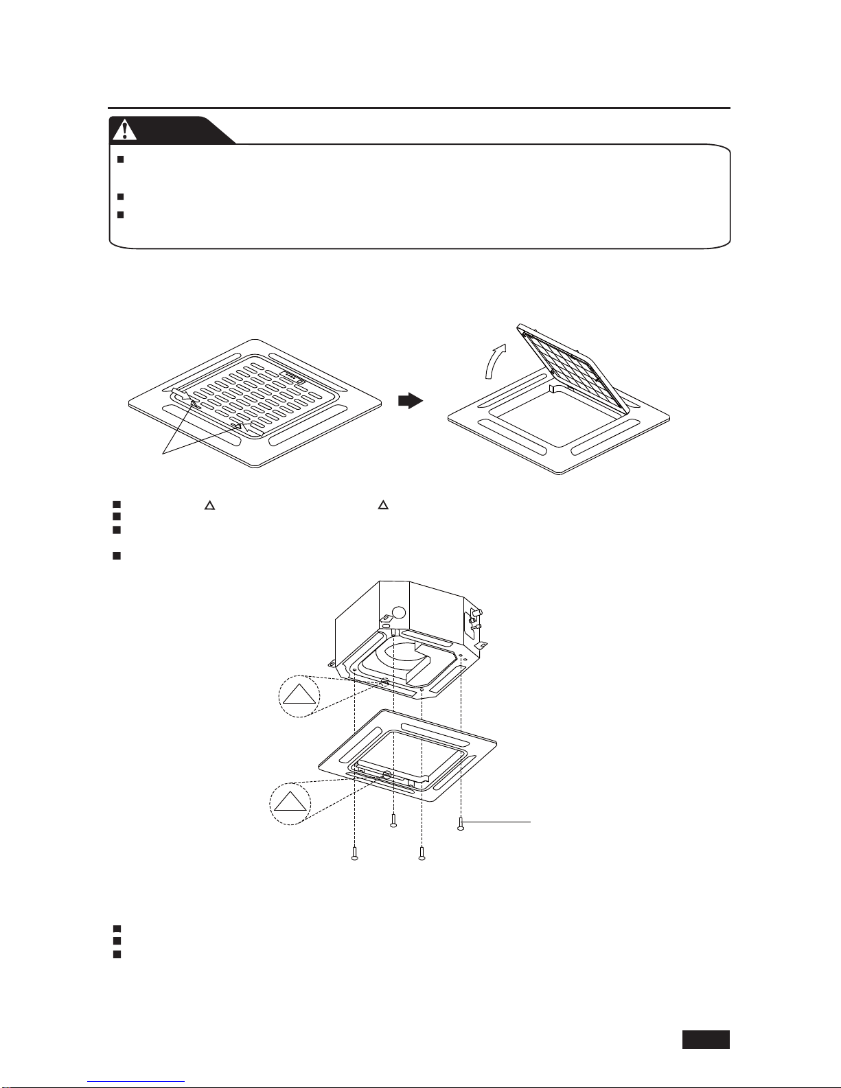
2.3.6.1 Push the two grille switches simultaneously, then lift the grille up and remove the air inlet grille.
2.3.6.2 Install the panel
Align the mark “ ” on the panel with the same mark “ ” on the main body.
Fix the panel to the main body with the 4 screws.
Tighten the screw evenly to make sure there is no gap between the main body and panel, and the edge of panel should contact
the ceiling well.
Connect the wire of swing motor to the corresponding splice on main body.
Grille switch
Screw (with panel)
2.3.6.3 Install the air inlet grille
Hang the hook behind the air inlet grille on to the panel.
Connect the wire of display to the corresponding plug on main body.
Cover the air inlet grille and grille switch.
Page 20
7
GB-19
2
Nam e of Accessories
Manual
Q‘ty(pc)
Shape
Use
<User manual>,
<Remote controller manual> (or
<Wired controller manual>)
2
Hook
For installation
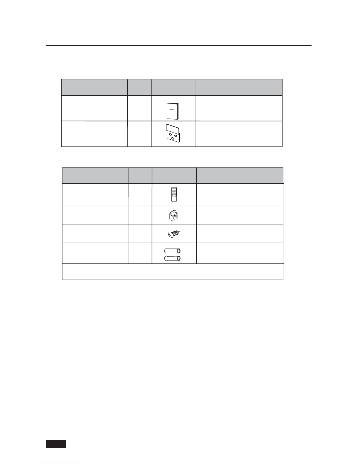
The following accessories are supplied with the indoor unit. The type and quantity may differ depending on the specifications.
2. INDOOR UNIT INSTALLATION
2.4 CONSOLE TYPE INDOOR
2.4.1 Accessories
1
Nam e of Accessories
Q‘ty(pc)
1
Shape Use
To remote
control the air conditioner
2
Battery
Tapped screw
Remote controller holder To hold the remote controller on the wall
For remote controller
2
Remote Controller
To fix the remote controller holder
Note: The accessories related to remote controller will be unavailable for the models with wired
controller. For wired controller accessories, please refer to attached manual of wired controller.
The following accessories are related to remote controller.
2.4.2 Installation site choosing
■ Where it is out of direct sunlight.
■ Where the airflow is not blocked.
■ Where an optimum air distribution is ensured.
■ Where the condensate can drain correctly and safely.
■ Install the indoor unit on a wall/ceiling that prevents vibration and is strong enough to hold the product weight.
■
Maintain sufficient clearance around indoor unit for maintenance and servicing.
■ Where the air filter can be removed and cleaned easily.
■
Where the piping between the indoor & outdoor units is within the allowable limits.
■
Install the indoor unit 1m or more away from the TV or radio to prevent the screen from being distorted or noise from
being generated.
■
Install the indoor unit as far away as possible from fluorescent and incandescent lights so that the remote control can
be operated well.
Page 21
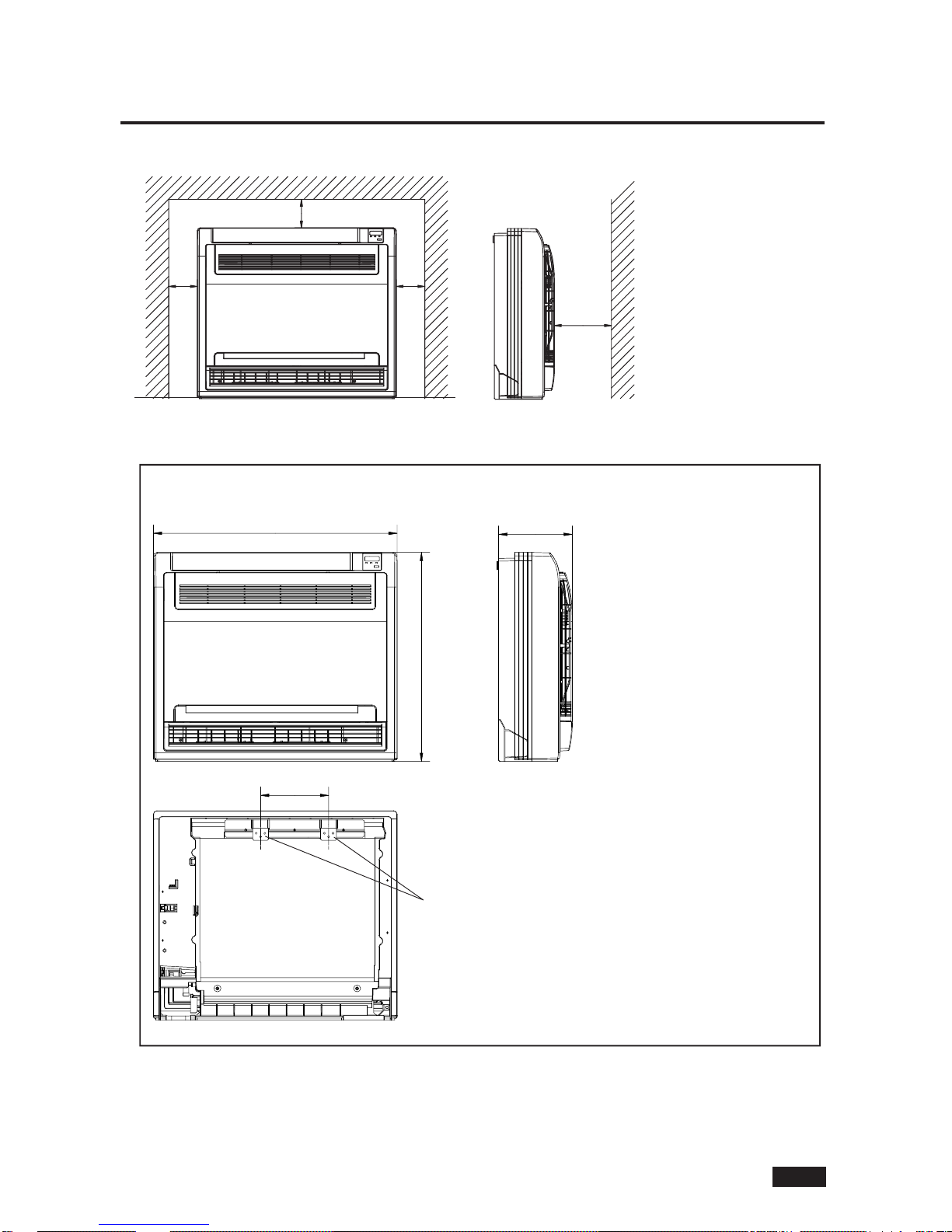
7
GB-20
≥100mm
≥100mm
≥100mm
≥1000mm
SPACE REQUIREMENT FOR INDOOR UNIT
The size of Outline dimension
Unit: mm
2. INDOOR UNIT INSTALLATION
195mm
Hook
700mm
210mm
600mm
Confirm that there is enough room for installation and maintenance.
Page 22
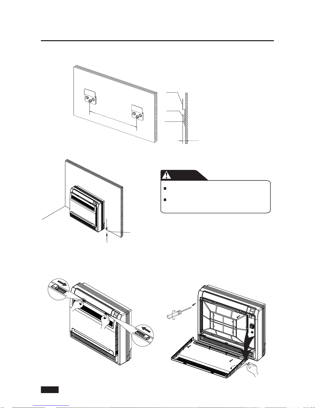
7
GB-21
2. INDOOR UNIT INSTALLATION
2.4.3.1 Fix the hook with tapping screw onto the wall.
2.4.3 Install the indoor unit
2.4.4 How to connect the pipes and wires
2.4.4.1 Push the two switches simultaneously, then open the panel.
2.4.4.2 Remove the string and take off the panel.
The unit must be installed vertically.
CAUTION
195mm
Hook
Tapping
screw
Washer
<6mm
2.4.3.2 Hang the indoor unit on the hook.
There should be no gap between unit and
the ground.
No gap between unit and the ground
Page 23
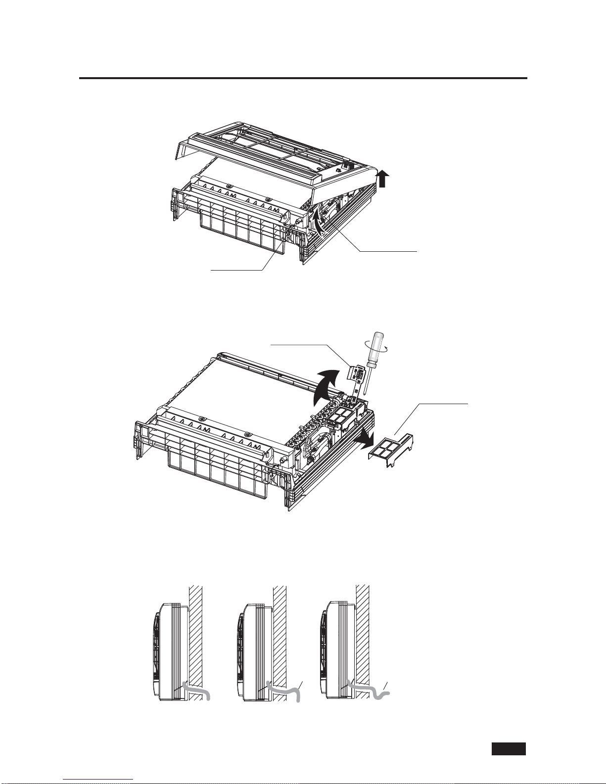
7
GB-22
2. INDOOR UNIT INSTALLATION
2.4.4.3 Remove 4 screws, and then remove the frame from bottom side. Piping connection port and drain hose connection port can
be observed after take off the frame.
Drain hose connection port
Piping connection port
2.4.4.4 Remove the installation bearer, and take off control box cover. Wiring terminator can be observed.
Installation bearer
Control box cover
2.4.5 Install the drain pipe
Bend
S shape
The drain line must not have a trap anywhere in its length, must pitch downwards, and must be insulated up to the outside wall.
O
X
X
Page 24
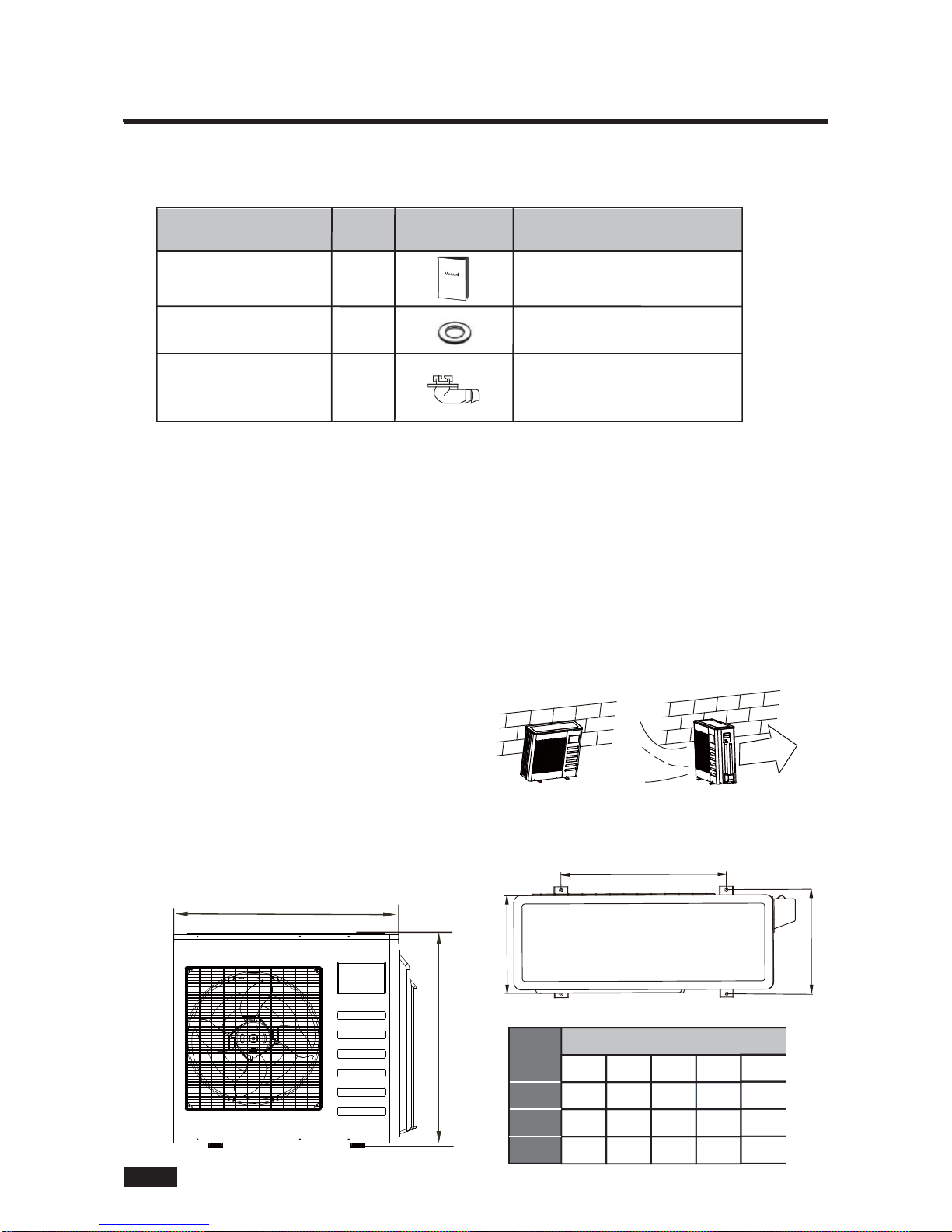
7
GB-23
3. OUTDOOR UNIT INSTALLATION
3.2 INSTALLATION SITE CHOOSING
■ Where it is out of rain or direct sunlight.
■ Where it is well-ventilated and free from obstacles near the air inlet and air outlet.
■ Where does not increase the operating noise or vibration of the outdoor unit.
■ Where does not cause any drainage problem with discharged water.
■ Install the outdoor unit properly at a place that is durable enough to the weight of the outdoor unit.
■ Where provides appropriate clearances as outlined
■ Where the piping between the indoor and outdoor units is within the allowable limits.
■ In regions with snowfall and cold temperatures, avoid installing the outdoor unit in areas where it can be covered by
snow. If heavy snow is expected, a field supplied ice or stand and field supplied-installed wind baffle should be
installed to protect the unit from snow accumulation and blocked air intake.
■ When installing the outdoor unit in a place that is
constantly exposed to a strong wind, it is recommended
that a wind baffle be used.
X
O
Strong wind
3.3 OUTDOOR UNIT MOUNTING DIMENSION
W
H
B
A
D
Outline dimension
900 860 315 333
W H D A B
990 965 345 366
27
36
845 700 320 335
18
590
624
560
Model
The following accessories are supplied with the outdoor unit. The type and quantity may differ depending on the specifications.
3.1 ACCESSORIES
1
1
Name of Accessories
Manu al
Q‘ty(pc)
Shape
Use
1
<Installation manual>
Drain outlet
Connect drainage hose for outdoor unit.
Gasket
Seal the drainage outlet for outdoor unit.
Page 25
GB-24
3. OUTDOOR UNIT INSTALLATION
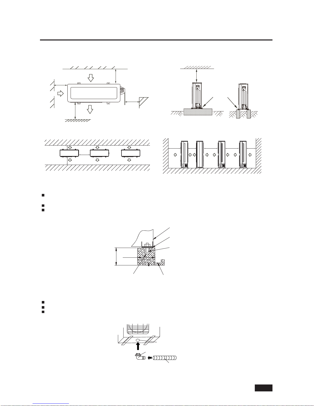
3.4 SPACE REQUIREMENT FOR OUTDOOR UNIT
>30cm
>30cm
>200cm
>60cm
(Wall or obstacle)
Maintain channel
Air outlet
Air inlet
M
P
Air inlet
N
>60cm
Fix with bolt
Single Unit Installation
Before installation, check strength and horizontality of the base so that abnormal sound does not
generate.
Fix the base firmly with anchor bolts (M10) to prevent it from collapsing.
Install the foundation and vibration-proof rubbers to directly support the bottom surface of the fixing
leg that is in contact with the bottom plate of the outdoor unit.
3.5 INSTALL THE OUTDOOR UNIT
≥100mm
100~300mm
Outdoor unit
Vibration-proof rubber
Anchor bolt (M10)
Drainage (Wide 100mm x Depth 150mm)Mortar Hole (Φ100mm x Depth 150mm)
>200 >50 >300 >300 >30
>60
>200
>30
Parallel connect the two units or above
Parallel connect the front with rear sides.
Connect the drain outlet with an extension drain hose
Fit the gasket onto drain outlet.
Insert the drain outlet into the base pan hole of outdoor unit, and rotate 90 degree to securely assemble them.
3.6 INSTALL THE DRAIN PIPE FOR OUTDOOR UNIT
unit:cm
unit:cm
Base pan hole
of outdoor unit
Drain hose
(Field supply)
Gasket
Drain Outlet
Page 26
4. REFRIGERANT PIPING WORK
7GB-25
Check if the height difference between indoor unit & outdoor unit and the total length of refrigerant pipe
meet system requirement.
Refrigerant piping work follows the indoor unit and outdoor unit installation, connect the pipe at the indoor
side first, then the outdoor side.
Always keep ends of tubing sealed by placing a cap or covering with tape during installation and do NOT
remove them until you are ready to connect the piping.
Be sure to insulate any field piping all the way to the piping connection inside the unit. Any exposed piping
may cause condensation or burns if touched.
When the outdoor unit is the top position and the difference of level is over 10m, it is recommended that set
a oil return bend every 5~8m in the gas pipe. The radius of oil reture bend should be over than 10cm.
CAUTION
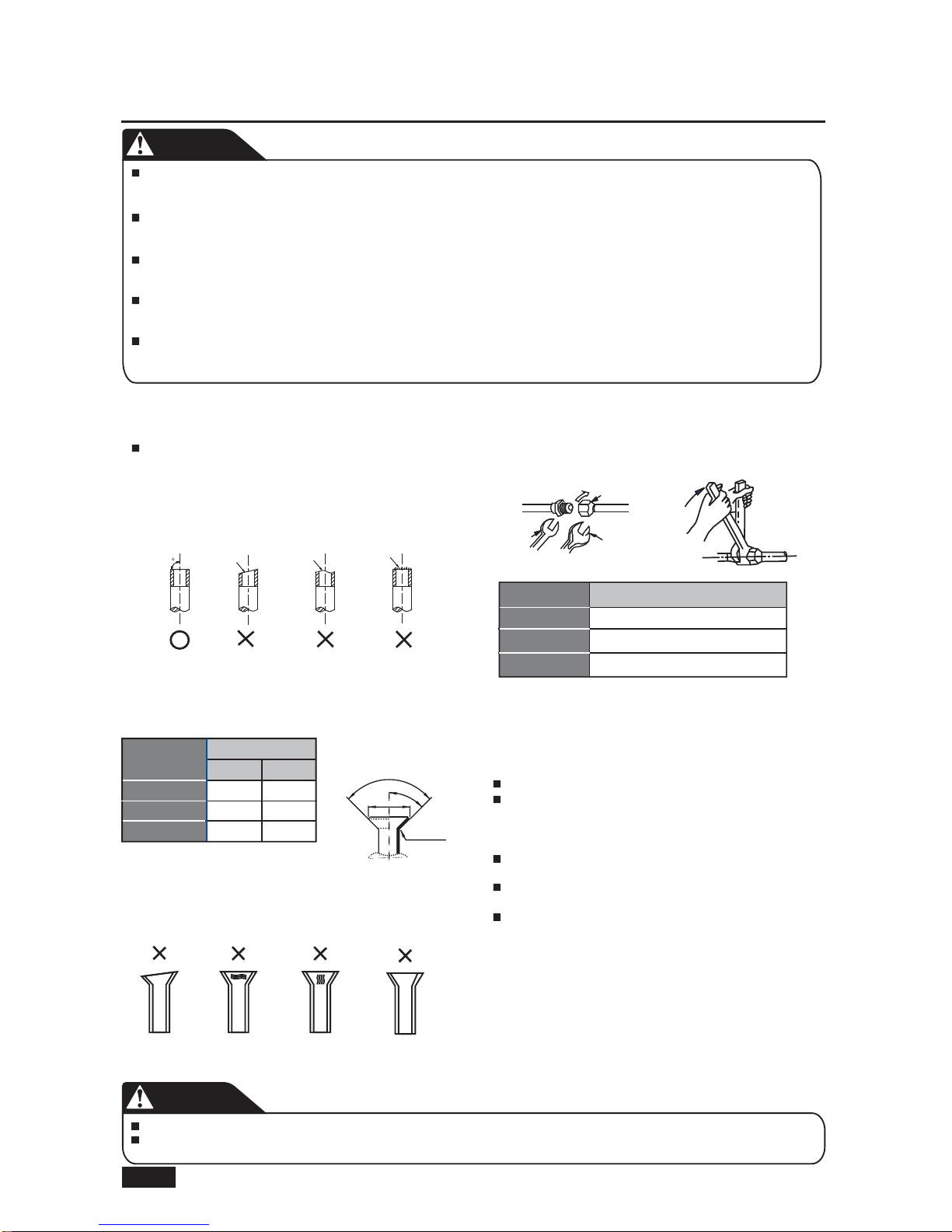
4.1 FLARING
NOTE
Tools required for flaring are pipe cutter, reamer, flaring
tool and pipe holder.
90
Oblique Rough Burr
Outside diameter
A(mm)
Max
8.7
Ø
6.35mm
Ø
9.52mm
Ø
12.7mm
12.4
15.8
8.3
12.0
15.4
Min
R0.4~0.8
45
°
±
2
90
°
±
4
A
In case of needing brazing, work with Nitrogen gas blowing.
Improper torque will cause flare damage or gas leaks.
CAUTION
TorqueTubing size
18 ~ 20 N.m
25 ~ 26 N.m
35 ~ 36 N.m
6.35mm
Ø 9.52mm
Ø 12.7mm
Use separate thermal insulation pipes for gas & liquid pipes.
The thickness above is a standard of the indoor temperature
of 27°C and humidity of 80%. If installing in an unfavorable
conditions such as near bathrooms, kitchens, and other similar
locations, reinforce the insulation.
Insulation’s heat-resistance temperature should be more than
120°C.
Use the adhesives on the connection part of insulation t o
prevent moisture from entering.
Repair and cover any possible cracks in the insulation specially
check the bent part or hanger of pipe.
4.1.1 Using a pipe cutter to cut the pipe to the requested
length. Ensure that the cut edge remains at 90° with
the side of the pipe.
4.1.2 Use a reamer to remove burrs with the cut surface
downward so that the chips do not enter the pipe.
4.1.3 Carry out flaring work using flaring tools as below.
4.1.4 Check if the flaring is properly made. See incorrectly
flared pipes sample below.
4.2 PIPING WORK
4.2.1 Align the center to tighten the flare nut and finish
connection using two wrenches.
Flare nut
Wrench
Torque wrench
4.2.2 Select the appropriate insulation material for refrigerant
pipe. (Min. 10mm, thermal insulating foam C)
Inclined Damaged Surface Cracked Uneven Thickness
Ø
Page 27
GB-26
4. REFRIGERANT PIPING WORK
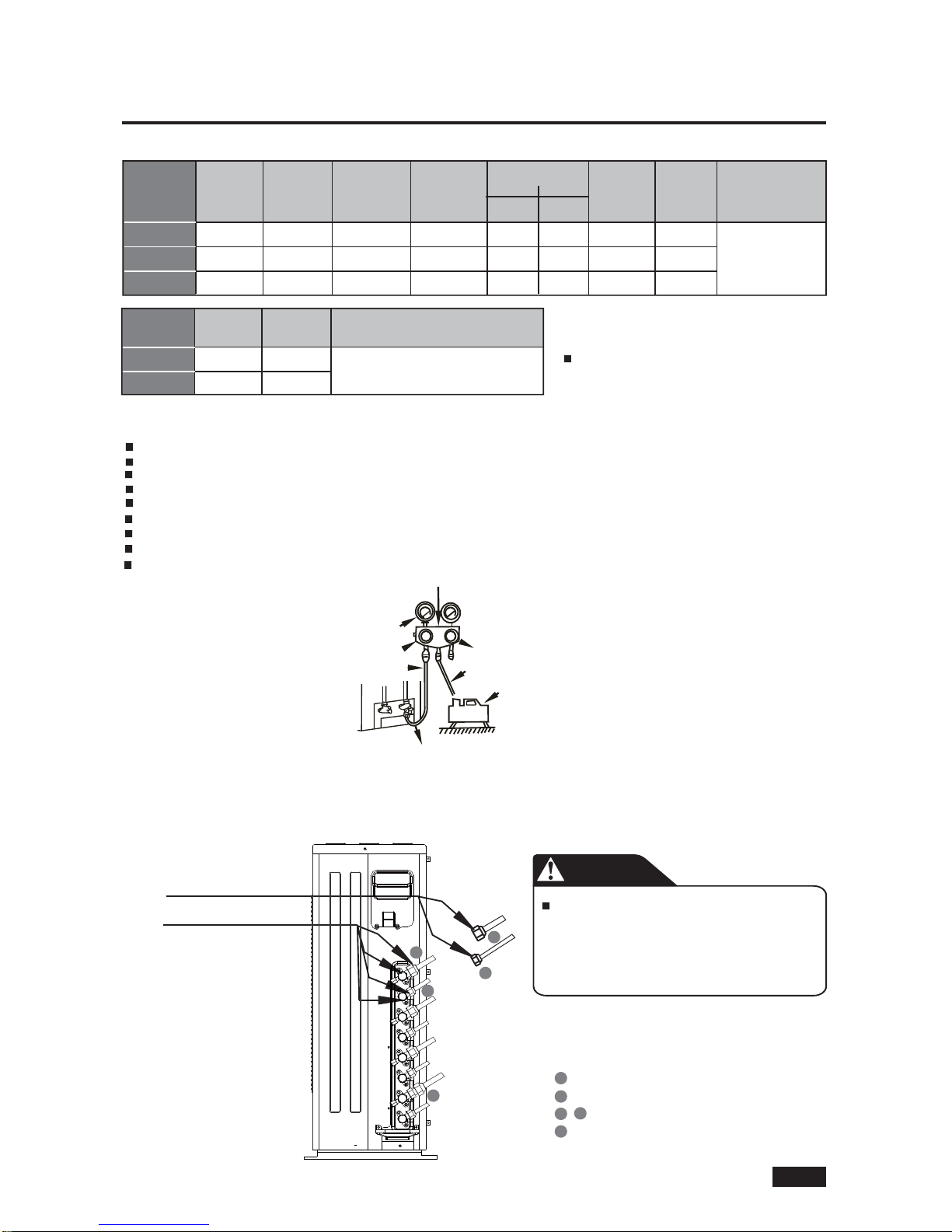
After the piping work is finished, make sure to check the connection part of each refrigerant pipe and confirm that there is no gas leak by
applying soapy water to them or by using a leak detector specific for HFC refrigerants. Refer below picture for illustration.
: Low pressure stop valve
: High pressure stop valve
: Indoor unit flare nuts
: Piping adaptor of 18K indoor
Check-point of indoor unit
Check-point of outdoor unit
4.3 REFRIGERANT PIPE
Gas Side
Model
Ø6.35mm×2 Ø9.52mm×2
10
Liquid Side
Total Allowable
pipe length (m)
Max. Height
difference (m)
Charge less
length (m)
Additional charge
(R410A)
18
27
36
Ø6.35mm×3
Ø9.52mm×3
10
10
10
30
45
60
20
25
30
10
10
(Total piping length chargeless length)
×15 g/m
NOTE
When the pipe length is longer than charge less
length, the additional refrigerant should be added
according to the piping length.
4.4 AIR EVACUATION
Connect the charge hose from the manifold gauge to the service port of the gas side packed valve.
Connect the charge hose to the port of the vacuum pump.
Fully open the handle Lo of manifold gauge.
Operate the vacuum pump to evacuate air from the system until 76cmHg.
Close the handle Lo of manifold gauge.
Repeat above steps for each system (indoors)
Fully open the valve stem of the packed valves.
Remove the charging hose form the service port.
Securely tighten caps of packed valve.
-76 cmHg
Handle Lo
Handle Hi
Charge hose
Charge hose
Vacuum pump
Packed valve
Manifold valve
Compound gauge Pressure meter
4.5 LEAKAGE TEST
Ø6.35mm×4
Ø9.52mm×4
Allowable pipe
length for each
indoor(m)
OU higher
than IU
IU higher
than OU
10 15
15
15
Max. Height
difference of
indoors (m)
20
15
Gas Side
Model
(indoor)
Ø6.35mm Ø9.52mm
Liquid Side
09/12
18
Ø6.35mm
Ø12.7mm
Install Piping adapter (from
Ø12.7 to Ø 9.52)
at outdoor side for 18K indoor
Note
Make sure that the indoor unit (A, B,...)
connects to the valves and signal wire
terminal (A, B, ...) of outdoor unit as
identified with their respective matched
connection.
CAUTION
3
1
5
2
4
1
3
5
2
4
Page 28
5. WIRING
7
GB-27
Model
H07RN-F; 3×1.5mm
2
Power Cord(Field Supply)
Indoor/outdoor connecting wiring
(Field Supply)
Power
Supply
Phase
1-Phase
220-240V~ 50Hz
Frequency and volt
14.5A
Rated Current
Fuse Rating(Field Supply)
25A
5.1 WIRING FOR OUTDOOR UNIT
H07RN-F; 4×1.0mm
2
27
H07RN-F; 3×2.5mm
2
1-Phase
220-240V~ 50Hz
16.5A
25A
H07RN-F; 4×1.0mm
2
36
H07RN-F; 3×4.0mm
2
1-Phase
220-240V~ 50Hz
21.5A
35A
H07RN-F; 4×1.0mm
2
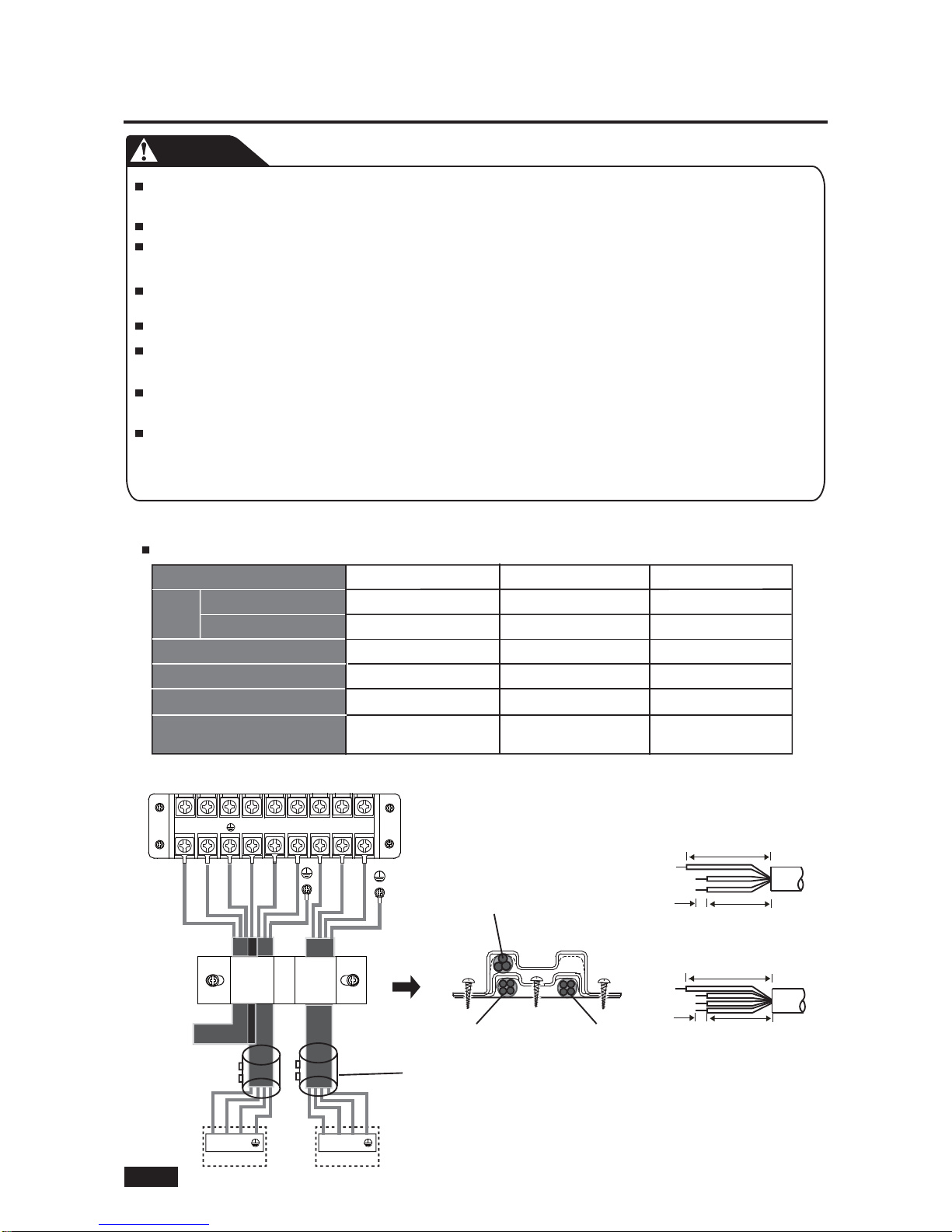
Power supply and connecting wires specification
All the electrical connections must be carried out by qualified installers and all the wirings must be
connected according to the wiring diagram.
Make ground connection prior to any other electrical connections.
All power sources must be turned off before wiring work and do not turn on the power until you have
made sure all the wirings have been safety checked.
A main switch and circuit breaker or fuse must be installed, the capacity should be above 1.5 times of
maximum current in circuit.
An individual branch circuit and single socket used only for this appliance must be available.
Wire cross section is depending on the rated current and national, state and local electrical wiring
code. Consult local building codes and National electrical code for special requirement.
If the supply cord is damaged, it must be replaced by the manufacturer, its service agent or similarly
qualified persons in order to avoid a hazard.
The unit must be connected to the main power supply by means of a circuit breaker or a switch with a
contact separation of at least 3mm in all poles. Installation of a residual current device (RCD) having
a rated residual operating current not exceeding 30mA is advisable.
CAUTION
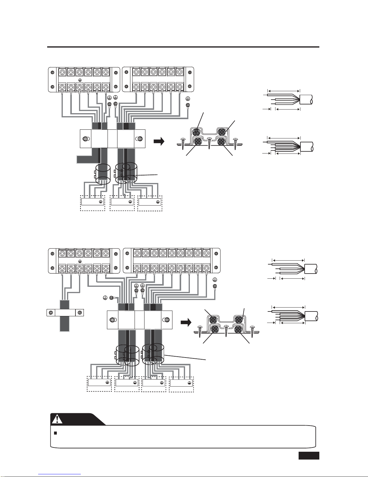
LN S
Indoor A
LN S
Indoor B
L L(A)N
N(A) N(B)
S(A) L(B)
S(B)
POWER
SUPPLY
POWER SUPPLY
To Indoor A To Indoor B
Clamp Filter: Clamp to indoor/outdoor
connecting wire (Field supply)
60mm
40mm10mm
Power input cord
GND
Connective Cable
60mm
40mm10mm
GND
38QUS018DS2*/ 38VNM218713
18
Page 29
GB-28
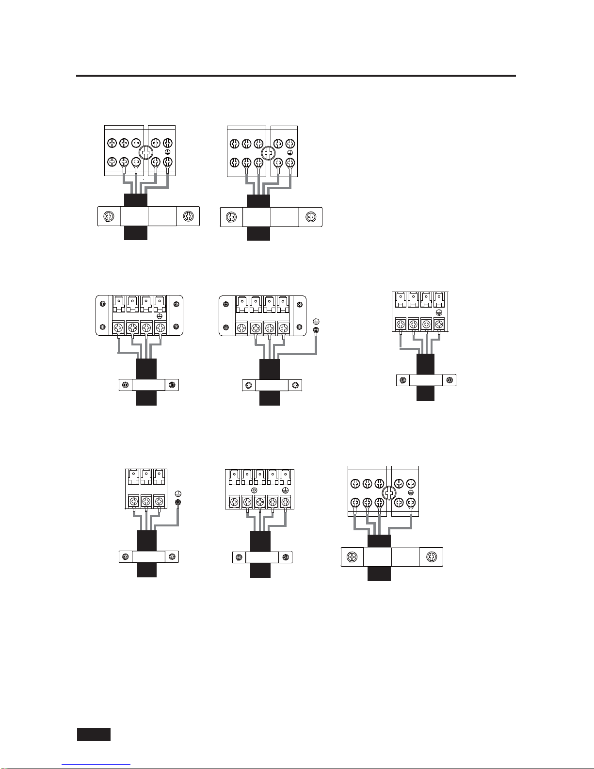
LN S
Indoor A
LN S
Indoor B
POWER
SUPPLY
POWER SUPPLY
To Indoor A To Indoor B
Clamp Filter: Clamp to indoor/outdoor
connecting wire (Field supply)
60mm
40mm10mm
Power input cord
GND
Connective Cable
60mm
40mm10mm
GND
L L(A)N
N(A)
N(B)
S(A)
L(B)
S(B)
L(C)
N(C) S(C)
5. WIRING
LN S
Indoor C
To Indoor C
LN S
Indoor C
POWER
SUPPLY
To Indoor A
To Indoor B
Clamp Filter: Clamp to indoor/outdoor
connecting wire (Field supply)
60mm
40mm10mm
Power input cord
GND
Connective Cable
60mm
40mm10mm
GND
L L(A)N
N(A)
N(B)
S(A)
L(B)
S(B)
L(C)
N(C) S(C)
LN S
Indoor D
To Indoor D
N(D)L(D)
S(D)
LN S
Indoor A
LN S
Indoor B
To Indoor C
Make sure that the indoor unit (A, B,...) connects to the valves and signal wire terminal (A, B, ...) of
outdoor unit as identified with their respective matched connection.
CAUTION
38QUS027DS3*/ 38VNM327713
38QUS036DS4*/ 38VNM436713
Page 30
7GB-29
5.2 WIRING FOR INDOOR UNIT
5. WIRING
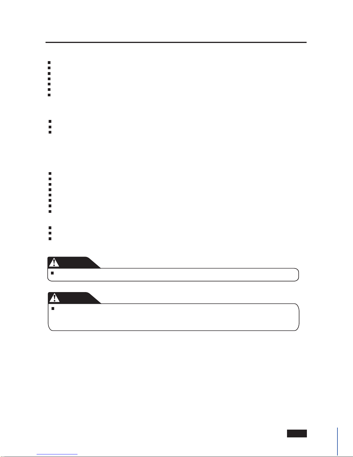
W 1(L) 2(N) S
Wall mounted (QHF009~18)
To outdoor
Duct (QSM012~18)
Cassette (QTD009)
Console (09~18)
S1(L) 2(N)
To outdoor
W
To Outdoor
1(L)
2(N)
S
W
Cassette (QTD012~18)
To Outdoor
L
N
S
L
NS
To Outdoor
L(1) 1 2(N) S
To outdoor
Wall mounted (HVF-09~18)
Duct (QSM009/SVM-09~18)
S
N
To outdoor
L
L
N
S
To outdoor
Cassette (CVS-09~18)
Page 31
GB-30
6. FINAL CHECK AND TRAIL OPERATION
To complete the installation, perform the following checks before the trial operation.
Strength of the installation site for both indoor and outdoor sides, confirm no obstruction of the unit air outlet or return.
Tightness of Refrigerant piping connection and confirm no leakage
Electric wiring connections are correctly completed and unit has been grounding connected
Check the total length of the piping and record the volume of the additional charged refrigerant
The power supply should complying with the rated voltage of the air conditioner
Insulation of the pipe
Drainage
6.1 FINAL CHECK LIST
Set the air conditioning under the COOLING mode with the remote controller (or manual button) and check the running status of both
indoor unit and outdoor unit. In case of any malfunction, resolve it according to chapter “Trouble shooting” in the “Service Manual”.
Indoor unit
Whether the buttons (such as ON/OFF, MODE, TEMPERATURE, FAN SPEED etc.) on the remote controller work well.
Whether the louver moves normally.
Whether the room temperature is adjusted well.
Whether the indicator lights on the display panel are normal.
Whether the “manual” button works well.
Whether the drainage is normal.
Whether there is a vibration or abnormal noise during the operation.
Whether the indoor unit works well in COOLING or HEATING mode.
Outdoor unit
Whether there is a vibration or abnormal noise during the operation.
Whether the wind, noise or condensed generated by the air conditioner have disturb your neighborhood.
Whether there is any refrigerant leakage.
6.3 TRAIL OPERATION
When restart the unit, there will be approximately 3 minutes delay to run for protection.
CAUTION
6.2 MANUAL OPERATION
Manual operation can be accessed by pressing manual button on display panel.
Press the manual button repeatedly to change modes as follows:
Once = AUTO mode [heat, cool or fan, 24
°C
and auto fan speed
.
Twice = COOLING mode [switch to AUTO mode after 30 minutes (mainly used for trial operation)]
Three times = OFF
The multi-system air conditioner can not be in different operating modes at the same time, such as one unit being in the
“COOL” mode and one unit being in the “HEAT” mode.
When conducting different operations, the “HEAT” mode will be given priority. The indoor unit which operates in “COOL”
or “FAN” mode will stop and display “P5”.
CAUTION
Page 32
BEIJER RET AB
Stortorget 8
Malmö
Sweden
 Loading...