

Page 1

42PQV/38VBH
¥
L
L
O
Y
D
’
S
R
E
G
I
S
T
E
R
Q
U
A
L
I
T
Y
A
S
S
U
R
A
N
C
E
I
S
O
9
0
0
1
R-410A
INST ALLA TION MANUAL
Page 2
42PQV/38VBH
1:1 inverter Heat pump system
ENGLISH
GB - 1
For operation and maintenance instructions of this unit as well as installation
instructions, refer to owner’s manuals.
Contents
Page
General information....................................................................................................................... 2
Dimensions and weight ................................................................................................................. 3
Connections................................................................................................................................... 3
Minimum clearances and operating limits ..................................................................................... 4
Material supplied and system charge............................................................................................ 5
Choosing the installation site......................................................................................................... 6
Warnings: avoid............................................................................................................................. 7/8
Installation for indoor unit .............................................................................................................. 9/10
Refrigerant connections ................................................................................................................ 11/13
Check............................................................................................................................................. 14
Electrical connection for indoor unit .............................................................................................. 15
Electrical connection for outdoor unit ............................................................................................ 16
Electrical connection ..................................................................................................................... 17
Electrical data ................................................................................................................................17
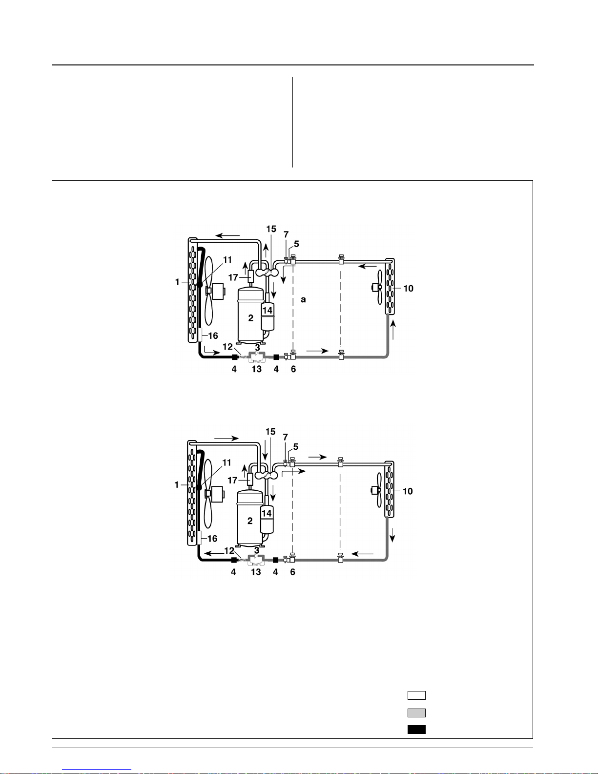
Pump down and refrigerant cycle .................................................................................................. 18
Operating test address selector and fault code............................................................................. 19
Unit configuration, remote configuration, guide for owner and accessories................................. 20
Maintenance and Troubleshooting................................................................................................ 21
ATTENTION INSTALLERS AND SERVICE TECHNICIANS!
AIR CONDITIONER WITH R-410A – QUICK REFERENCE GUIDE
•R-410A refrigerant operates at 50%-70% higher pressures than R-22. Be sure that servicing
equipment and replacement components are designed to operate with R-410A.
•R-410A refrigerant cylinders are pink.
• R-410A refrigerant cylinders have a dip tube which allows liquid to flow out with the cylinder in a vertical
position with the valve at the top.
•R-410A systems should be charged with liquid refrigerant. Use a commercial type metering device
in the manifold hose in order to vaporize the liquid refrigerant before it enters in the unit.
•R-410A, as other HFCs, is only compatible with oils selected by the compressor manufacturer.
•A vacuum pump is not enough to remove moisture from oil.
•Oils absorb moisture rapidly. Do not expose oil to atmosphere.
•Never open system to atmosphere while it is under vacuum.
•When the system must be opened for service, break vacuum with dry nitrogen.
•Do not vent R-410A into the atmosphere.
•Use only Carrier matching indoor units and outdoor units (Table I).
Indoor unit Outdoor unit Power supply Oil type Quanty cc
42PQV009 38VBH009
220-240V, 50/60Hz
PVE 440
42PQV012 38VBH012 PVE 550
Table I
Page 3
42PQV/38VBH
GB - 2
General information
Unit installation
Read this instruction manual thoroughly before starting the
installation.
• This equipment contains R-410A refrigerant, a substance
that is not depleting the ozone layer but must be disposed
of in a proper manner. When disposing of the unit after its
operational life, remove it carefully.
The unit must be delivered to an appropriate disposal center
or to the original equipment dealer.
• Carefully recover refrigerant within this unit before final
disposal or When servicing. Never vent refrigerant to
atmosphere.
• R410A systems operate at higher pressures than standard
R22 systems.
Do not use R-22 service equipment or Components on
R410A epuipment.
• This unit complies with low-voltage (EEC/72/23) and electromagnetic compatibility (EEC/89/336) directives.
• Check that the impedance of the mains power supply is in
conformance with the unit power input indicated in the
electric data table IV, on page 17 (EN 61000-3-11).
• The installation must be carried out by a qualified installer.
• Follow all current national safety code requirements.
In particular ensure that a properly sized and connected ground
wire is in place.
• Check that voltage and frequency of the mains power supply are
those required for the unit to be installed; the available power
must be adequate to operate any other possible appliances
connected to the same line.
Also ensure that national safety code requirements have been
followed for the mains supply circuit.
• The mains supply must be connected to the indoor unit.
• Connect indoor and outdoor units with field-supplied copper
pipes by means of flare connections.
Use insulated seamless refrigeration grade pipe only, (Cu DHP
type according to ISO1337), degreased and deoxidized, suitable
for operating pressures of at least 4200kPa and for burst
pressure of at least 20700kPa.
Under no circumstances must sanitary type copper pipe be used.
• Where necessary, used field-supplied 16-17mm I.D. PVC pipe of
appropriate length and with the correct thermal insulation for the
condensate drain extension.
• After the installation thoroughly test system operation and
explain all system functions to the owner.
• Leave this manual with the owner for consultation during future
periodic maintenance.
• Use this unit only for factory approved applications: the unit
cannot be used in laundry or steam pressing premises.
Outdoor unit is suitable for outdoor installation.
• Coupling units which have different control systems, may cause
irreversible damage and void the warranty protection.
The manufacturer declines any liability for system malfunction
resulting from unapproved coupling.
IMPORTANT:
During the unit installation make first refrigerant connections
and then electrical connections. If unit is uninstalled first
disconnect electrical cables, then refrigerant connections.
WARNING:
Disconnect the mains power supply switch and wait over
2 minutes without touching any internal parts of the unit
before servicing the system or handing any internal parts
of the unit.
• The manufacturer declines any liability for damage resulting from
modifications or errors in the electrical or refrigerant connections.
• Failure to observe the installation instructions or use of the unit
under conditions other than those indicated in Table III
“Operating limits”, will immediately void the unit warranty.
• Failure to observe electric safety codes may cause a fire hazard
in case of short circuits.
• Inspect equipment for damage due to improper transportation or
handling: file an immediate claim with the shipping company.
Do not install or use damaged units.
• In case of any malfunctioning turn the unit off, disconnect the
mains power supply and contact a qualified service engineer.
• Maintenance of the refrigerant circuit must only be carried out by
qualified personnel.
• Do not open the remote control to avoid possible damage.
In case of malfunctioning contact a qualified service engineer.
• Control batteries contain polluting elements.
When exhausted they must be disposed of according to local
requirements.
• All of the manufacturing and packaging materials used for
your new appliance are compatible with the environment
and can be recycled.
• Dispose of the packaging material in accordance with local
requirements.
Page 4
GB - 3
42PQV/38VBH
ENGLISH
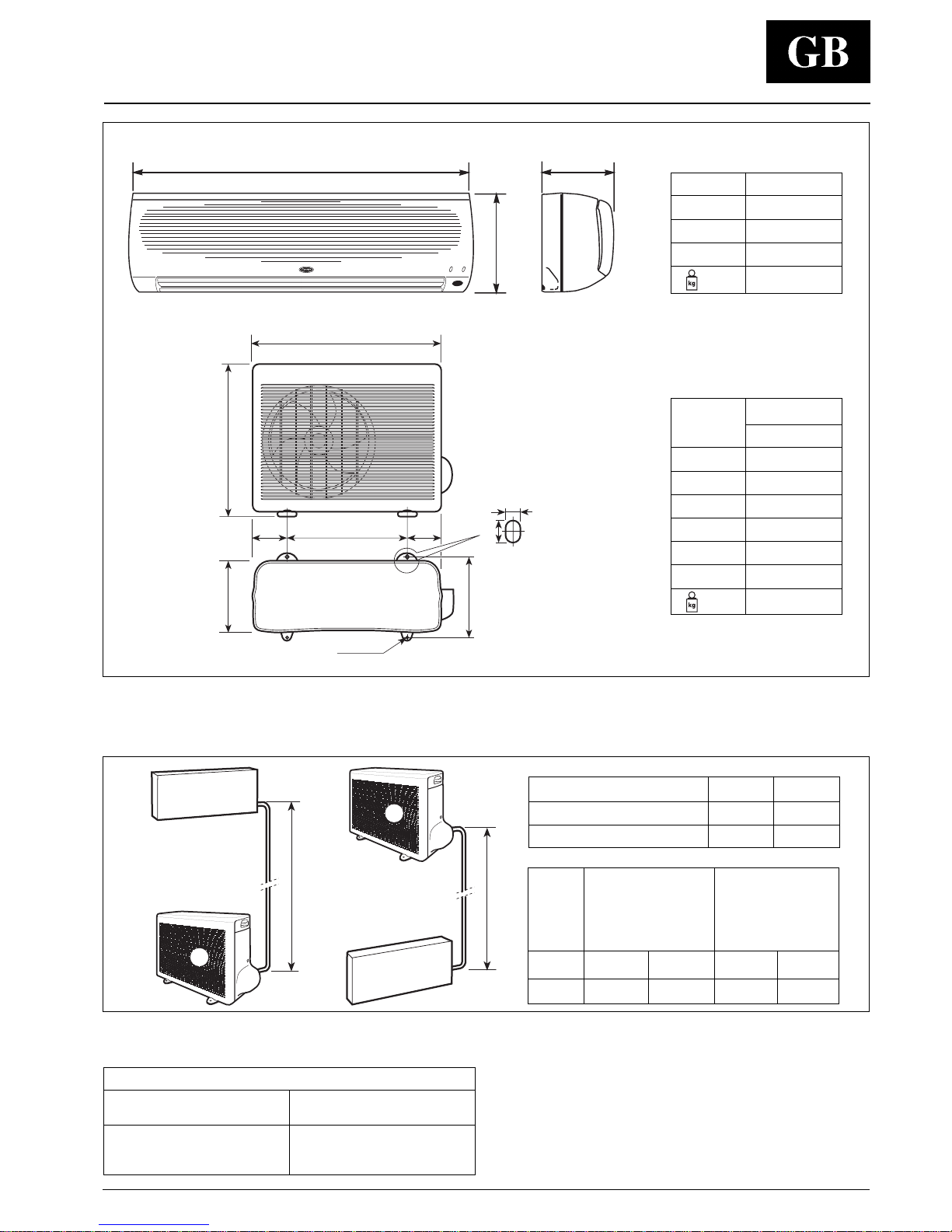
Dimensions and weight
Pipe diameter Pipe diameter
Model Gas Liquid Gas Liquid
(Suction) (Liquid) (Suction) (Liquid)
mm inches
009 9.52 6.35 3/8” 1/4”
012 12.7 6.35 1/2” 1/4”
Table II : Connections
Outdoor unit
Indoor unit
Height difference
Model 009 012
Max.height difference 8 10
Max.pipe length 10 15
All fittings are flare type.
Use only refrigeration grade pipes, (Cu DHP type according
to ISO 1337), seamless, degreased, deoxidized and
suitable for operating pressures of at least 4200 kPa and
with a burst pressure of 20700kPa.
Under no circumstances must sanitary type copper pipe
be used.
Minimum nominal thickness
Pipe diameter
inches-mm
1/4”-6,35
3/8”-9,52
1/2”-12,70
Minimum nominal
thickness(mm)
0,80
0,80
0,80
Ø 8,3
C
DEE
F
A
B
8,3
13,3
AC
B
Mod.
38VBH
009 / 012
A mm 750
B mm 590
C mm 280
D mm 470
E mm 140
F mm 310
kg 33 - 37
Mod.
42PQV
A mm 790
B mm 260
C mm 186
kg 8.6
Page 5
42PQV/38VBH
GB - 4
D
E
B
A
C
F
A
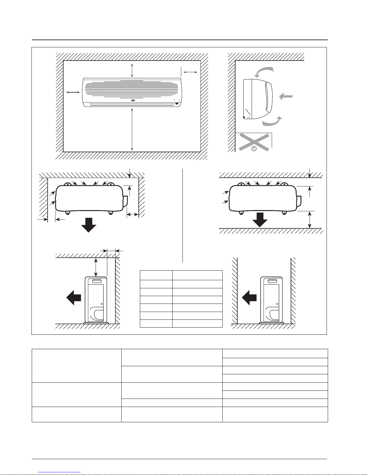
Minimum clearances and operating limits
Model 009-012
A mm 50
B mm 100
C mm 400
D mm 50
E mm 300
F mm 400
Maximum conditions
outdoor temperature 46°C
indoor temperature 32°C d.b.; 23°C w.b.
Minimum conditions
outdoor temperature 15°C
indoor temperature 21°C d.b.; 15°C w.b.
Maximum conditions
outdoor temperature 24°C d.b.; 18°C w.b.
indoor temperature 27°C d.b.
Minimum conditions outdoor temperature –10°C d.b.
Nominal single-phase voltage 220V-240V, 50/60Hz
Operating voltage limits min. 198V – max. 264V
T able III: Operating limits
(1)
Cooling
Heating
Mains power supply
Obstacle
90
min.
1900
min.
100
min.
200
min.
WARNING:
During heat pump operation unit will undergo several defrost cycles to
eliminate ice that might possibly collect on the outdoor unit in very low
ambient temperatures. In these cycles, fan speed will automatically stop,
louvre(flap) will be fixed at horizontal position and cannot be varied until
defrost cycle is completed.
Notes: 1. Data referred to the outdoor unit only.
d.b. - dry bulb; w.b. - wet bulb
Page 6
GB - 5
42PQV/38VBH
ENGLISH
Material supplied and system charge
The following field-supplied items are required to complete the installation.
Name Specification
009: Ø (3/8”) 9.52 mm (Gas) / Ø (1/4”) 6.35 mm (Liquid)
Connection pipe
012: Ø (1/2”) 12.7 mm (Gas) / Ø (1/4”) 6.35 mm (Liquid)
Wall sleeve
Wall cap
Finishing tape PVC film
Fastening tape
Pipe insulation
Drain hose I.D. 16-17 mm
Sealer putty
- Power supply cable H07RN-F or higher
- Electrical connecting cable
Cable type: H07 RN-F, synthetic rubber insulation with Neoprene coating,
between indoor and outdoor unit
according to EN 60335-2-40 codes.
System charge
Size
Refrigerant Suitable up Maximum pipe lenght Maximum pipe elevation
charge (g) to (m) (m) (m)
009 720 10 10 8
012 1100 15 15 10
1. This appliance is designed to be used without additional refrigerant charge up to 10m for 42PQV009 and 15m for 42PQV012.
There is no need to charge and extract additional refrigerant according to the connecting pipe length within maximum pipe length.
2. In case of refrigerant charging due to refrigerant leak or service, charge exact amount of refrigerant using scale after evacuate the unit
with vacuum pump.
3. For reference, discharge/suction pressure at various temperature conditions and a rated compressor speed are provided service
manual.
Never charge and extract the refrigerant depending on discharge/suction pressure. This unit is inverter system whose compressor
speed is variable.
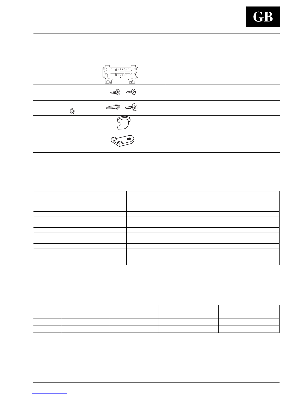
NAME and shape Q.ty Use
Wall hanging bracket 1 For indoor unit installation.
Screws 4xL10 2 For fixing unit and hanging bracket
Screws anchors and screws 6xL25
4 + 4 + 4 For wall hanging bracket installation.
Washers Ø 12
Drain fitting
1 For drainage of outdoor unit.
Mounting rubber 4 For outdoor unit installation.
Material supplied
The following installation accessories are supplied with unit. Use them as required.
Page 7
42PQV/38VBH
GB - 6
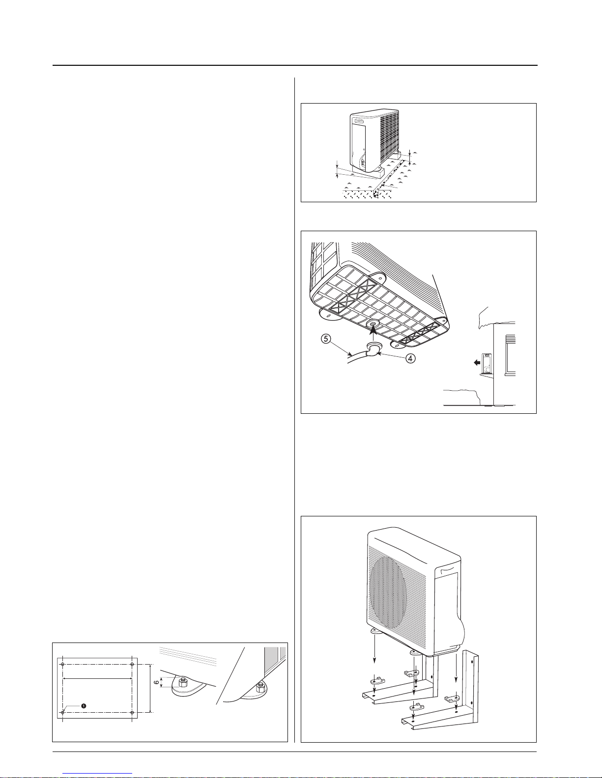
• Fix the unit with locally purchased bolts buried in the block to
prevent overturning due to strong gusts of wind.
• For heat pump models, unit must be adequately raised above
floor surface.
• To empty the condensate water to a drain while operating in
heating mode, insert the drain fitting into the hole underneath on
the centre of the base and use a vinyl pipe with a 16 mm inside
diameter.
It must not be used at temperatures below 0
°C (not available
for low temperature versions).
• If the unit is installed in areas where heavy snowfalls may occur,
it is necessary to raise its level at least 200 mm above the usual
snow level or alternatively to use the outdoor unit bracket kit.
Choosing the installation site
No. 4 Ø 8 mm pins.
Protrusion height from the
support surface max. 6 mm.
470 mm
310 mm
100 mm min.
20 mm gradient.
Gravel-filled trench.
Drain fitting
Vinyl pipe
Indoor unit
Positions to avoid:
• Exposed to direct sun.
• Too close to heat sources.
• On humid walls or positions with water hazard, e.g. laundry
premises.
• Where curtains or furniture may obstruct free air circulation.
Recommendations:
• Choose an area free from obstructions which may cause
irregular air distribution and/or return.
• Check that the wall surface is flat enough to allow easy and
safe installation.
The wall structure should be strong enough to carry the unit
weight and avoid deformation, rupture or vibration during
operation.
• Consider using an area where installation is easy.
• Choose a position that allows for the clearances required
(see drawing).
• Look for a position in the room which assures the best possible
air distribution.
• Install unit in a position where condensate can easily be piped to
an appropriate drain.
Outdoor unit
Positions to avoid:
• Too close to sources of heat radiation, vapour or flammable gas.
• Particularly dusty areas.
Recommendations:
• Choose a position protected from opposing winds.
• Choose a position sheltered from direct sun.
• Choose an area where air outlet and unit noise will not bother
your neighbours.
• Choose a position that allows for the clearances required.
• Floor structure should be adequately strong to support unit
weight and minimize vibration transmission.
• Consider a position which will not obstruct passageways or
doors.
Page 8
42PQV/38VBH
GB - 7
ENGLISH
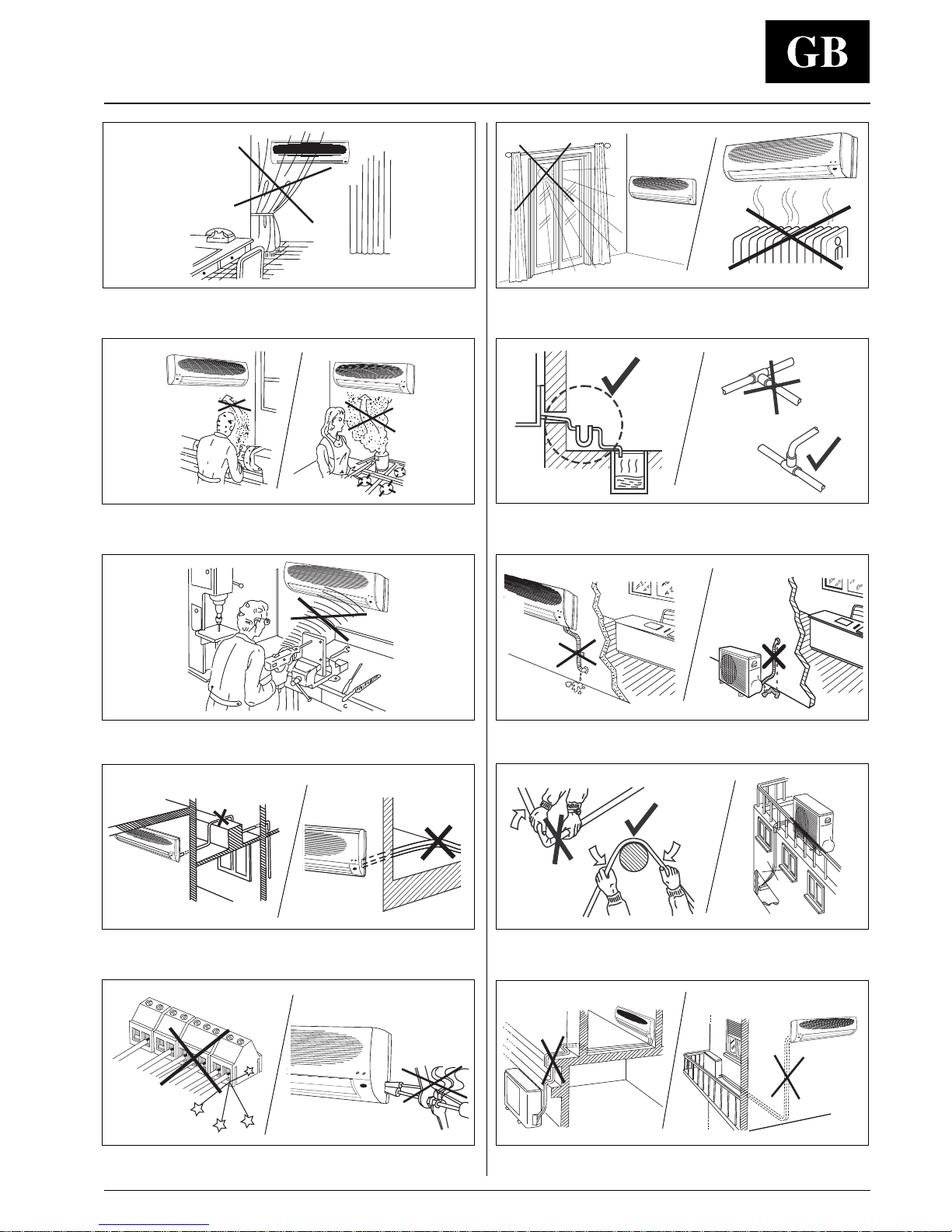
Exposure to direct sunshine, when unit is operating in cooling
mode; always use shutters or shades.
Positions too close to heating sources which may damage the unit.
Connecting condensate piping to sewage system drain without
appropriate trap. Trap height must be calculated according to the unit
discharge head in order to allow sufficient and continuous water evacuation.
Only partial insulation of the piping.
Installation not correctly leveled which will cause condensate dripping.
Flattening or kinking the refrigerant pipes or condensate pipes.
Excessive height difference between outdoor and indoor units.
Unnecessary turns and bends in interconnecting tubing. Excessive
interconnecting tube length.
Warnings: avoid…
Any obstruction of the unit air outlet or return.
Exposure to oil vapours.
Installation in areas with high-frequency waves.
Any rise in the condensate drain piping.
Horizontal condensate drain piping with less than 2% slope.
Slack on electrical connections. Disconnecting refrigerant
connections after installation: this will cause refrigerant leaks.
Page 9
42PQV/38VBH
GB - 8
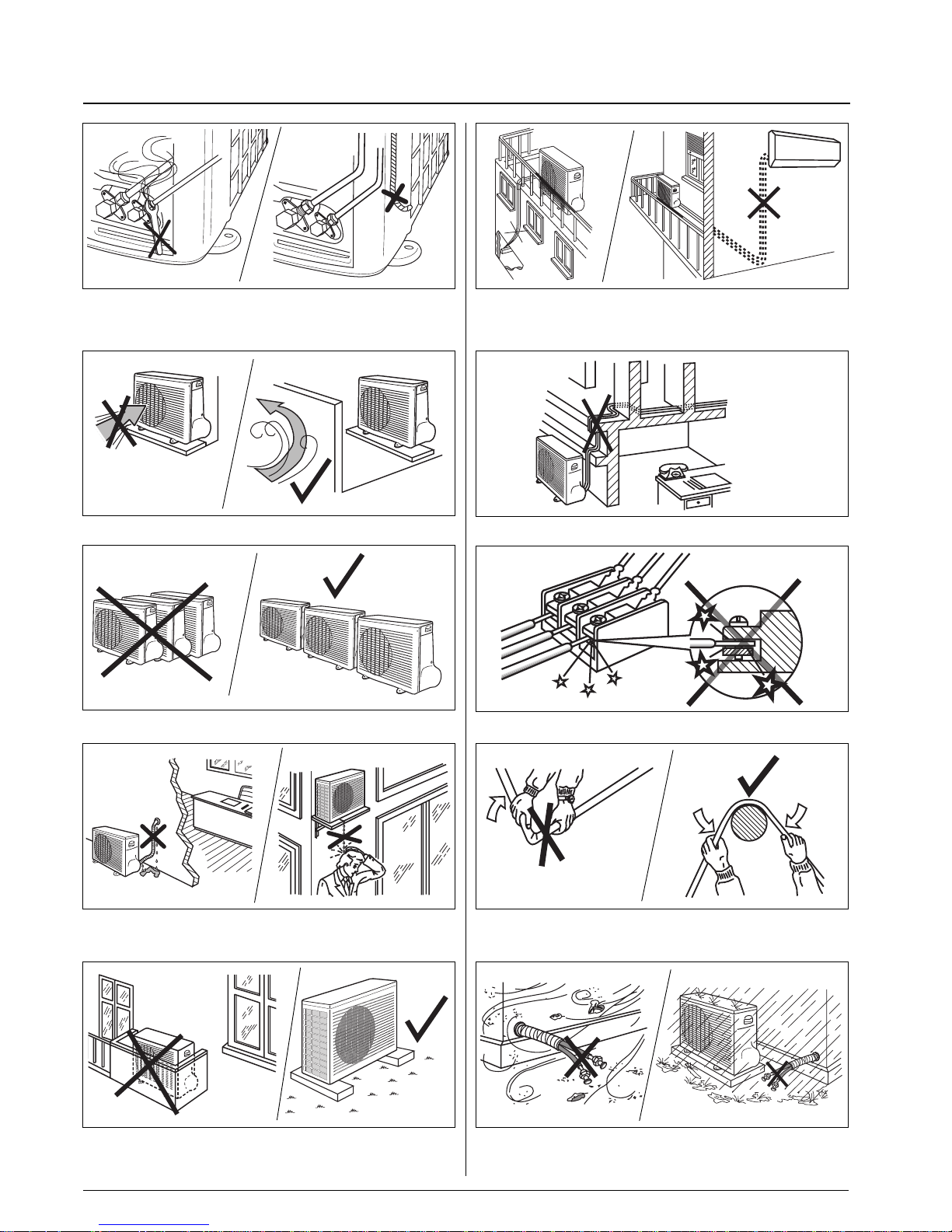
Excessive height difference between indoor and outdoor unit (see
Table II "Connections"). Excessive distance between indoor and
outdoor units. (see Table II "Connections").
Unnecessary turns and bends in the connecting pipes.
Any slack in the electrical connections.
Flattening or kinking of refrigerant or condensate pipes.
Soiling of pipe ends.
Allowing piping to get wet before connection.
Disconnecting the refrigerant connections after installation:
this will cause refrigerant leaks.
Connecting the condensate drain pipe to the outdoor unit.
Predominant head winds.
Multiple unit installation with units facing each other.
Insulating the connecting pipes only partially, which will cause dripping.
Dripping into passageways.
Any obstruction of the unit air outlet and intake or any obstacle that is too
close (see minimum clearances required). Installation on grassy ground
or soft surfaces (in these cases a solid foundation must be included).
Warnings: avoid....
Page 10
42PQV/38VBH
GB - 9
ENGLISH
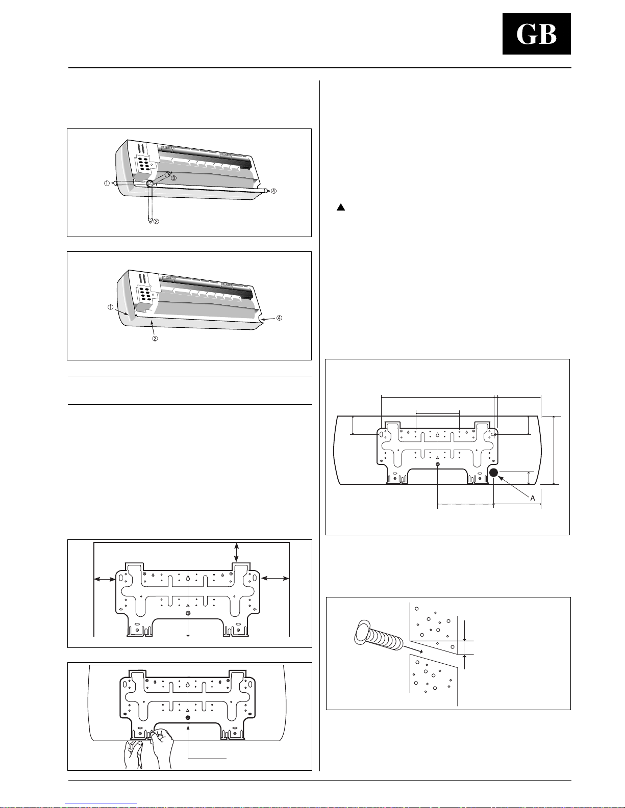
• The piping can be connected in the four ways indicated by ,
, and .
When the piping is connected to points , or , remove
the knock-out either at the side or at the bottom of the unit.
IMPORTANT NOTE:
Indoor unit has no refrigerant expansion device.
Installing the wall hanging bracket
• Install the wall hanging bracket so that it is level. Use a plumb
line if necessary.
• Be sure to leave the clearance spaces. (Refer to page 4).
• If the wall hanging bracket is not level, water may drip onto the
floor.
• Install the wall hanging bracket with a fixing that is strong
enough to withstand the weight of the unit.
• Before installing the wall hanging bracket, remove it from the unit
by pushing at the indicated parts at the bottom of the body.
• Fasten the wall hanging bracket to the wall with 4 or more screw
anchors through the holes near the outer edge of the bracket.
• Install the wall hanging bracket so that there is no gap between
the bracket and the wall.
• Check that the wall hanging bracket does not move.
This can cause noise during operation.
• If the unit is removed from the wall hanging bracket after installing
it onto the wall, remove it by pushing up the indicated MARKS
(
) at the bottom of the body. (Refer to page 10).
Marking the wall penetration for the
connection piping
Rear piping
• It is best for the piping to go through the wall behind the unit, so
that the unit hides the pipes.
• For this method of installation, make a 65 mm diameter hole in the
wall at point A.
• Drill a 65 mm diameter hole at a slope so that the outside end is
lower (5 - 10 mm) than the inside end.
This will ensure good drainage.
• Cut the wall sleeve to match the wall thickness and pass the pipe
through the hole.
Side or bottom piping
• Remove the knock-out in the unit and pass the pipes through
the wall.
• The pipe should slope downward and away from the unit to
ensure good drainage.
Indoor side
Outdoor side
5 ~ 10 mm lower
Remove screw
Plumb line
300
min.
120 min.
450
min.
450
110
23
245
51
110
56
40
260
180
Installation for indoor unit
Page 11

42PQV/38VBH
GB - 10
Routing the drain hose and refrigerant
piping
• Tie together the refrigerant pipe, the drain hose, and the
electrical connection cord.
• Route the refrigerant piping in the required direction, and bend
carefully avoiding pipe deformation.
Bind the drain hose and the electrical connection cord together
with fastening tape.
The drain hose should be at the bottom.
• For left-hand piping, fit the pipes and the wiring into the recess at
the back of the unit.
NOTE:
• Do not crush or kink the indoor piping. Avoid sharp bends with a
bend radius of less than 100 mm.
• Do not bend the same part of the pipe too often.
• Do not remove the flare nut from the indoor unit pipe until the
piping is connected.
• The recommended bending of the drain hose is shown.
Indoor unit piping
Left-hand piping
Bind with fastening tape
Drain hose
Indoor unit piping
Drain hose
Connection cord
Wall hanging
bracket
Hook
Hole
Installation for indoor unit
300
220
Installing the indoor unit body to the wall
hanging bracket
• Pass the pipes through the wall sleeve and then hook the indoor
unit body on top of the wall hanging bracket.
• For left-hand piping, hang the unit on top of the wall hanging
bracket and incline the unit using a tool such as a screwdriver
set between the middle area of the body and bottom right of the
wall hanging bracket.
Connecting the pipe can be done more easily if the unit is
inclined.
• Fix the bottom part of the unit to the wall hanging bracket, by
pushing it carefully unit the two bracket hooks fit into the marked
places at the base of the unit (a click will be heard).
Page 12
42PQV/38VBH
GB - 11
ENGLISH
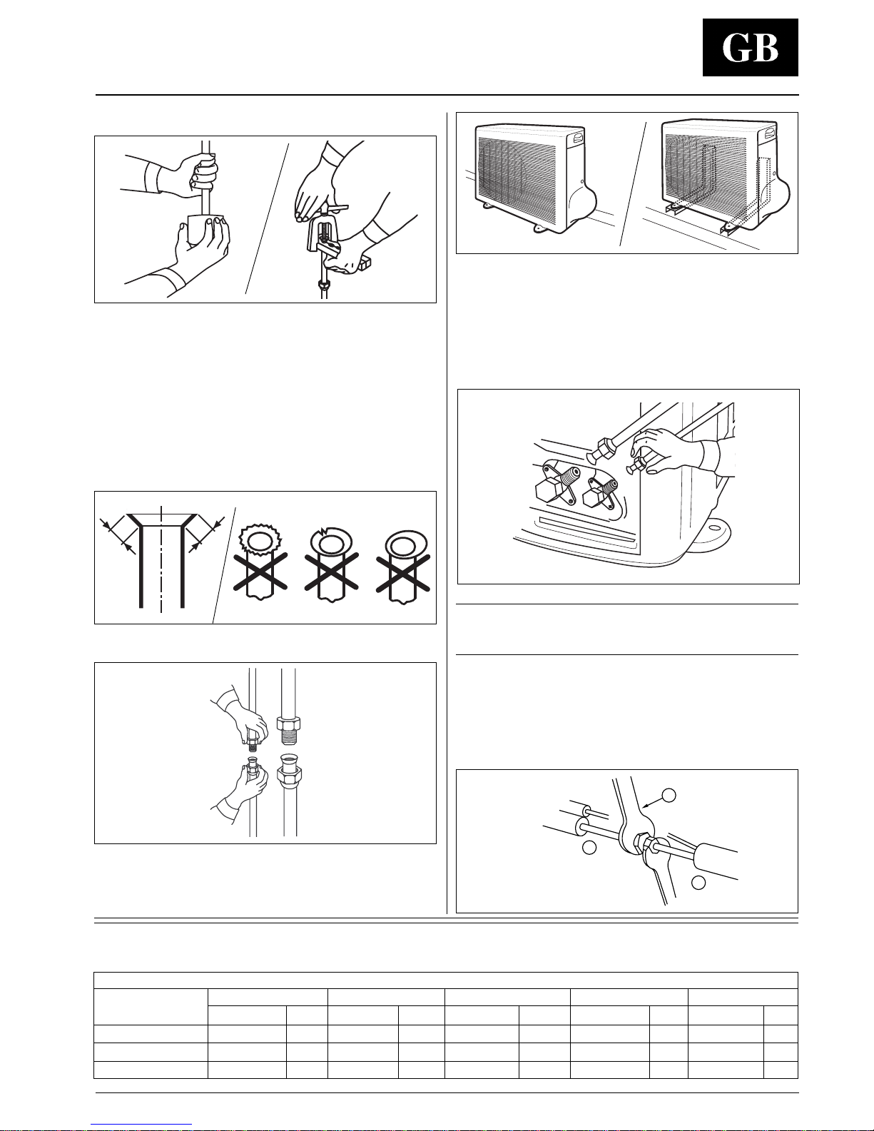
Tightening torque
Valve
Flare nut Valve cap Pressure port cap Valve needle Pressure port
Wrench mm Nm Wrench mm Nm Wrench mm Nm Wrench mm Nm Wrench mm Nm
1/4” 17 18 22 20 - - Allen(hex.)4 9 - 0.34
3/8” 22 42 22 20 17 16-18 Allen(hex.)4 9 - 0.34
1/2” 27 55 25 40 17 16-18 Allen(hex.)4 13 - 0.34
The unit can be installed:
on the floor;
on the wall using the bracket kit.
Connect tubing in accordance with the limits shown on Table II
(Connections).
Finger-tighten the fitting several turns, then tighten it with a
wrench by applying the tightening torque indicated in the table.
Flaring the ends of the tubing
Remove protective caps from copper tube ends.
Position tube end downward, cut the tube to the requested length
and remove the burrs with a reamer.
Do not leave system open to atmosphere any longer than minimum
required for installation.
Oil in the compressor is extremely susceptible to moisture
absorption.
Always keep ends of tubing sealed during installation.
Remove flare nuts from the unit connections and place them on the
tube end.
Flare the tube with the flaring tool.
Flare end must not have any burrs or imperfections.
The length of the flared walls must be uniform.
Refrigerant connections
L
L
IMPORTANT:
Open the three way valves only after fitting has been
tighten.
Connection to unit
Insufficient tightening torque will cause gas leaks.
Overtightening the fittings will damage the tube flaring and
cause gas leaks.
Lubricate the tube end and thread of the flare fitting with antifreeze oil.
Finger-tighten the fitting several turns, then tighten it fully with
two wrenches by applying the tightening torque indicated in the
table.
Adjustable wrench or torque wrench
Outdoor end
Indoor end
3
1
2
Page 13
42PQV/38VBH
GB - 12
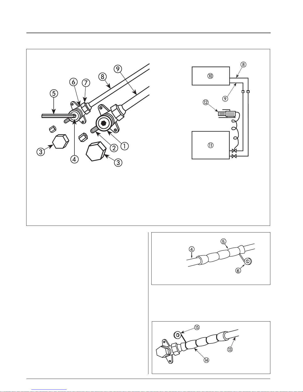
Refrigerant connections
Pipe
Pipe insulation
Fastening tape
Three-way valve (liquid)
Needle valve
Valve cap
Valve needle
Allen (hex. head) wrench
Three-way valve (liquid)
Use only a vacuum pump to purge air from the piping.
NEVER use the system compressor as a vacuum pump.
NEVER use the unit refrigerant gas to purge the connecting
pipes.
No additional refrigerant has been provided in the unit for this
purpose.
Remove the caps from the three-way valves.
Create a vacuum with a vacuum pump connected to the service
connection of the suction shut-off valve (gas), as shown, keeping
the shut-off valves completely shut until a 50 Pa (0.5 mbar)
vacuum has been reached.
Now open the liquid valve for 3 seconds, then quickly shut it to
check for possible leaks.
After the leak check, fully open the three-way valves.
Replace caps and check for leaks.
Once all connections have been completed, check for leaks by
using a leak detector specific for HFC refrigerants.
Flare nut
Liquid line (small diameter)
Gas line (large diameter)
Indoor unit
Outdoor unit
Vacuum pump
z
Once all connections have been completed, check for leaks by
applying soapy water to them.
Finally wrap connections with anti-condensate insulation and
tighten with tape, without exerting great pressure on the insulation.
Repair and cover any possible cracks in the insulation.
Connection pipes and electric cables between indoor and outdoor
units must be fixed to the wall with appropriate conduits.
Tube
Tube insulation
Fastening tape
Air purging
Page 14
42PQV/38VBH
GB - 13
ENGLISH
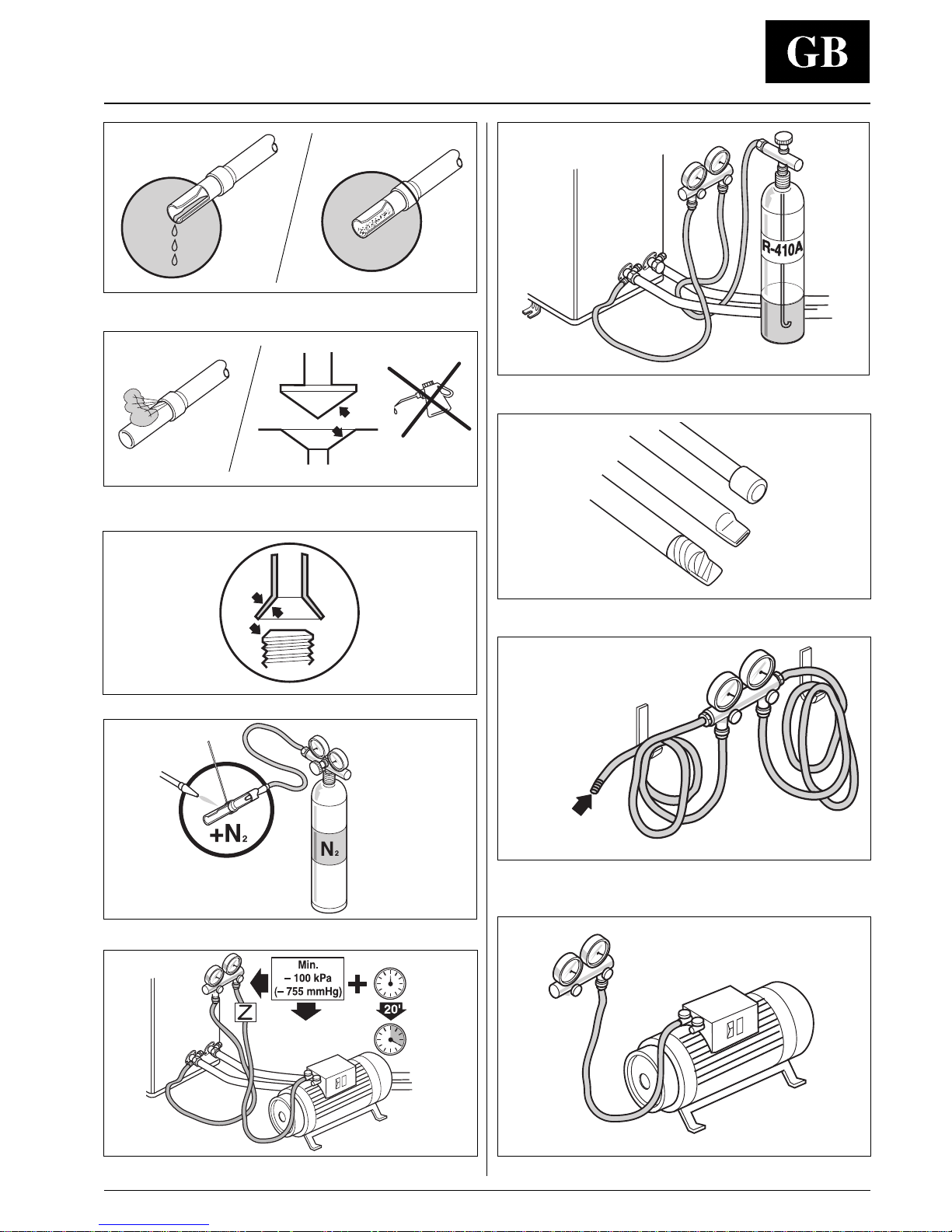
Charge liquid-no gas.
Copper tubes during storage.
Use tools designed for R-410A higher pressure.
Keep inside clean.
2-stage vacuum pump. Replace oil regularly.
No moisture.
No dust.
No leak.
No mineral oil.
Neat.
Dry nitrogen brazing.
Vacuum.
1/2” UNF (R-410A)
7/16” UNF (R-22)
Refrigerant connections
Page 15
42PQV/38VBH
GB - 14
Check
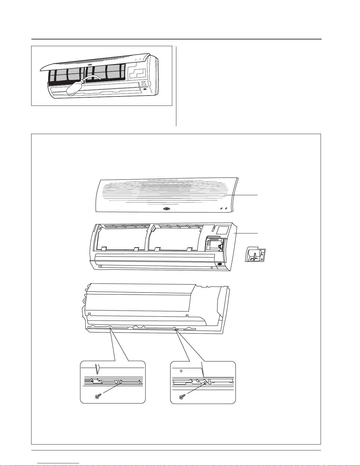
• Next, check the unit drain system by pouring some water into
the unit drain pan and ensuring that it flows freely through the
drain hose and that there is no leakage from any other part.
Use of additional screws
After installation, if there is a significant gap between the unit and
wall, it can be adjusted by securing the body to the wall hanging
bracket using 2 screws.
Screw holes can be only seen after removing the frame grille.
Grille
Front panel
Page 16
42PQV/38VBH
GB - 15
ENGLISH
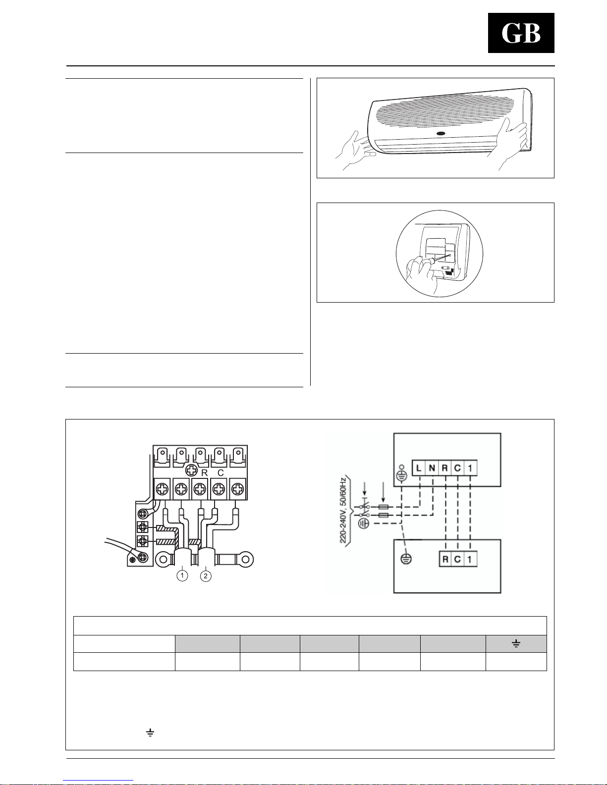
Minimum connection wire size (mm2)
Model L N R C 1
009, 012 1.5 1.5 1.5 1.5 1.5 1.5
L
N
1
IMPORTANT:
• Make refrigerant connections before electrical
connections.
When disconnecting, disconnect electrical connections before
refrigerant connections.
• Make ground connection prior to any other electrical
connections.
• The mains supply must be connected to the indoor unit.
• Make electrical connections between units prior to proceeding
to mains supply unit connection.
• Connect the wires to the terminals according to the wiring
diagram and firmly tighten.
• Before proceeding with the connection to the mains supply
locate live L and neutral N, then make connections as shown
in the wiring diagram.
• Check that the impedance of the mains power supply is in
conformance with the unit power input indicated on the electric
data table IV.
• Ensure that mains supply connection is made through a switch
that disconnects all poles, with contact gap of a least 3 mm.
• The indoor - outdoor unit connecting wires must be H07 RN-F
type (or higher), with synthetic rubber insulation with Neoprene
coating, according to EN 60335-2-40 codes.
• The mains supply connecting cable must be H07 RN-F type (or
higher), with synthetic rubber insulation with neoprene coating,
according to EN 60335-2-40 codes.
Notes:
All field electrical connections are the responsibility of the
installer.
Indoor unit wiring
Electrical connection for indoor unit
Terminal box legend, all models
L Live power supply
N Neutral power supply
R Live connection indoor/outdoor unit.
C Neutral connection indoor/outdoor unit.
1 Communication, indoor-outdoor units.
Earth
Power supply
Connecting cable, indoor-outdoor units.
Indoor unit
Outdoor unit
Main switch
Time-delay fuse or circuit breaker
• Lift the front panel up to the top of the unit; in this way the front
panel will be separated from the unit.
• Remove the plastic cover of the terminal board.
• Make the electrical connections to the terminal board as per the
wiring diagram.
• When the electrical connections are completed, refit the terminal
board cover and fix the cables with the special cable holders.
• Fix the front panel to the latch of the frame grille.
Page 17
42PQV/38VBH
GB - 16
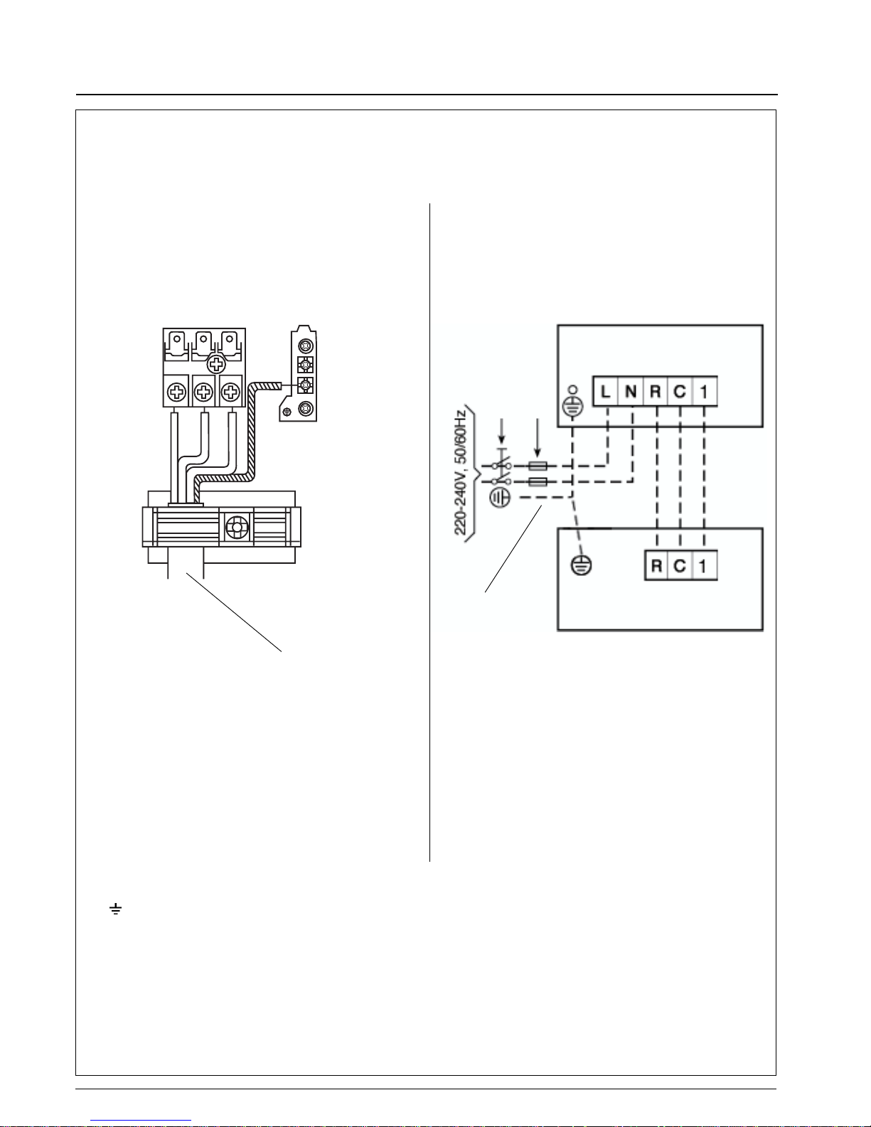
Electrical connection for outdoor unit
Connecting cable, indoor-outdoor units
(field wiring).
Mains supply connecting cable
(field wiring).
Indoor unit
Outdoor unit
Main switch
Time-delay fuse or circuit breaker
(see table IV "Electrical data").
Terminal box legend
Earth
L Live power supply
N Neutral power supply
R Live connection indoor-outdoor units
C Neutral connection indoor-outdoor units
I Communication, indoor-outdoor units.
38VBH- 009 - 012
C
R
I
Page 18
GB - 17
42PQV/38VBH
ENGLISH
Electrical connections
Notes: 1. Outdoor unit is suitable for outdoor installation.
2. Wire size shown applies to line length up to 15 m.
3. The indoor - outdoor unit interconnecting wires must be H07 RN-F type (245 IEC 57) or higher, with synthetic rubber insulation with
Neoprene coating, according to EN 60335-2-40 codes.
4. The mains supply connecting cable must be H07 RN-F type (245 IEC 57) or higher, with synthetic rubber insuluation with Neoprene coating,
according to EN 60335-2-40 codes.
The mains supply must be connected to the indoor unit.
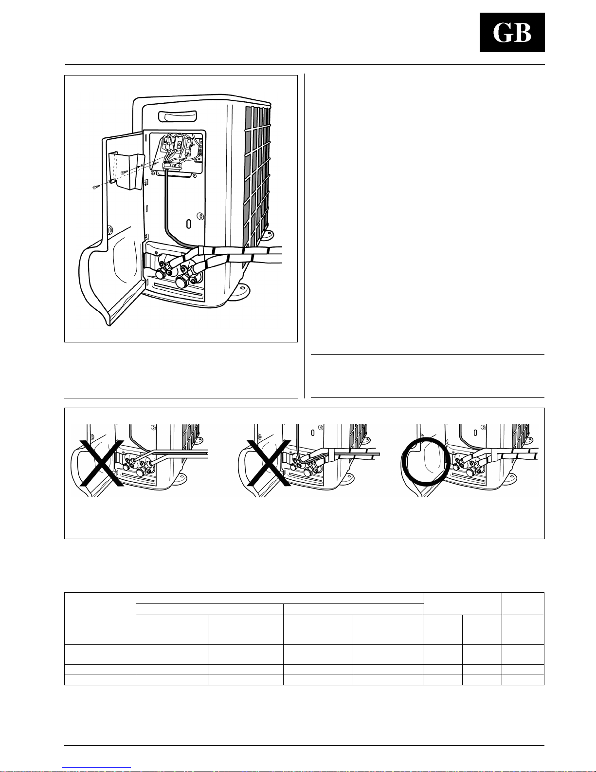
• Open control box panel (valve cover panel).
• Make electrical connections between units prior to proceeding to
mains supply unit connection.
• Connect the wires to the terminals according to the wiring
diagram and firmly tighten.
• Before proceeding with the unit connection to the mains supply
locate live L and neutral N, then make connections as shown in
the wiring diagram.
• Check that the impedance of the mains power supply is in
conformance with the unit power input indicated on the electric
data table IV.
• Ensure that mains supply connection is made through a switch
that disconnects all poles, with contact gap of a least 3 mm.
• The indoor - outdoor unit interconnecting wires must be
H07 RN-F type (245 IEC 57) or higher, with synthetic rubber
insulation with Neoprene coating, according to EN 60335-2-40
codes.
• The mains supply connecting cable, must be H07 RN-F type
(245 IEC 57) or higher, with synthetic rubber insulation with
Neoprene coating, according to EN 60335-2-40 codes.™
Notes:
1. All field electrical connections are the responsibility of the
installer.
IMPORTANT:
Make ground connection prior to any other electrical
connections.
When disconnecting, disconnect electrical connections before
refrigerant connections.
Table IV: Electrical data
Heat pump A W A W A W A W A mm
2
mm
2
38VBH-009 3.9 852 5.4 1010 4.2 950 5.3 1020 20 1.5 1.5
38VBH-012 5.2 1140 7.1 1370 5.8 1310 9.1 1745 20 1.5 1.5
Indoor-
outdoor
unit
Heating
Cooling
Power input
Main power
connections
(4)
Time-delay
fuse
gL type
Wire size
(2)
Nominal conditions
230V ~ 50Hz
ISO 5151.2/T1
indoor 27°C d.b. 19°C w.b.
outdoor 35°C d.b. 24°C w.b.
Peak conditions
198V ~ 50Hz
ISO 5151.2/T1
indoor 32°C d.b. 23°C w.b.
outdoor 43°C d.b. 32°C w.b.
Nominal conditions
230V ~ 50Hz
ISO 5151.2/High+
indoor 20°C d.b. 15°C w.b.
outdoor 7°C d.b. 6°C w.b.
Peak conditions
198V ~ 50Hz
ISO 5151.2/High+
indoor 27°C
outdoor 24°C d.b. 18°C w.b.
Wire size
(2-3)
Never be in contact any other electrical connections with naked refrigerant tube and service valve in order to avoid
electrical connection damage due to hot refrigerant tube.
Page 19
42PQV/38VBH
GB - 18
Pump Down and refrigerant cycle
Gas
Liquid + Gas
Liquid
Cooling cycle
Heating cycle
Legend:
Outdoor coil
Compressor
Check valve
Strainer
Vapor valve
Liquid valve
Service pressure port
Indoor until coil
Liquid distributor
Cooling + Heating expansion device
Heating expansion device
Additional suction acumulator
Reversing valve
Filter drier
Discharge muffler
Pump-down
Pump-down is an operation intended to collect all the system
refrigerant in the outdoor unit.
This operation must be carried out before disconnecting the
refrigerant tubing in order to avoid refrigerant loss to the
atmosphere, if it becomes necessary to disconnect the
refrigerant connections for unit repair, removal or disposal
in this case, after removal, unit must be delivered to an
appropriate disposal centre or the original dealer.
Refrigerant Cycle
Heat pump unit
Shut off the liquid valve with the Allen wrench.
Turn the system on in cooling with fan operating at high velocity.
(Compressor will immediately start, provided 3 minutes have
elapsed since the last stop).
After 2 minutes of operation, shut the suction valve with the same
wrench.
Turn the system off and switch mains supply off.
Disconnect tubing.
After disconnection, protect valves and tubing ends from dust.
Page 20

42PQV/38VBH
GB - 19
ENGLISH
Operating test, address selector and fault code
Fault code
Once a failure occurs with the indoor unit in operation,
the green or orange LED flashes at intervals of 0.5 seconds.
The fault code is deduced from the number of times the green
LED or orange LED flashes, blocking unit operation.
Between one flash cycle and the next one, a pause of 3 seconds
elapses.
Table V : Fault code
Green LED (indoor unit fault)
Code Description
2 Room air sensor fault
3 Indoor unit coil sensor fault
7 Indoor-outdoor units communication fault
8 Indoor fan motor fault
Continuance Indoor sensor wiring reversed
Orange LED (outdoor unit fault)
Code Description
1 Outdoor sensor fault
2 Indoor-outdoor units mis-matching
3 4way valve fault
4 Outdoor fan motor fault
5 Inverter control fault
6 Power module(IGBT) fault
7 Indoor-outdoor units communication fault
Operating test
• Perform the operating test after the units have been installed in
position and the gas leak test has been completed.
• Check all electrical connections(instructions and wiring diagram).
• Insert the batteries into the remote control and leave it OFF.
• Energies the system, turning the power supply ON.
• Press the
and buttons of the infrared remote control and
hold them pressed for more than 5seconds.
The display will be cleared, the time segments will display the icon
(Src1=service test).
• Press
button to transmit the service test signal to the unit.
After test has been completed, press
button to leave the test
menu.
Note:
When 30 minute have elapsed and no buttons have been pressed,
the remote control
will automatically exit the test menu and resume its normal operation.
Address selector
If you are installing two indoor units in the same room and you
want them to operate in independent mode, it is necessary to
assign each unit its own address so that each unit can operate via
its own remote control.
For configuration, proceed as follows:
Configuration (of the unit)
• Press the
and buttons of the infrared remote control and
hold them pressed for more than 5 seconds.
• The display will be cleared, the time segments will display the first
configuration item (rAdr=remote address) and the temperature
segments will display the default value of this configuration item
(Ab=control of both indoor units).
• Press either the
or button to change the default value (Ab)
to the new value (A) or (b).
• Press
button to transmit the new configuration to the unit.
• Press
button to leave the configuration menu.
Configuration (of the remote controller)
• Press the
and buttons of the infrared remote control and
hold them pressed for more than 5 seconds.
• The display will be cleared, the temperature segments will
display the first configuration item (CH=remote address) and the
time segments will display the default value of this configuration
item (Ab=control of both indoor units).
• Press either the
or button to change the default value (Ab)
to the new value (A) or (b).
• Press
button to transmit the new configuration to the unit.
• Press
button to leave the configuration menu.
Note:
When 30seconds have elapsed and no buttons have been
pressed, the remote control will automatically exit the
configuration menu and the procedure has to be restarted.
Page 21
42PQV/38VBH
GB - 20
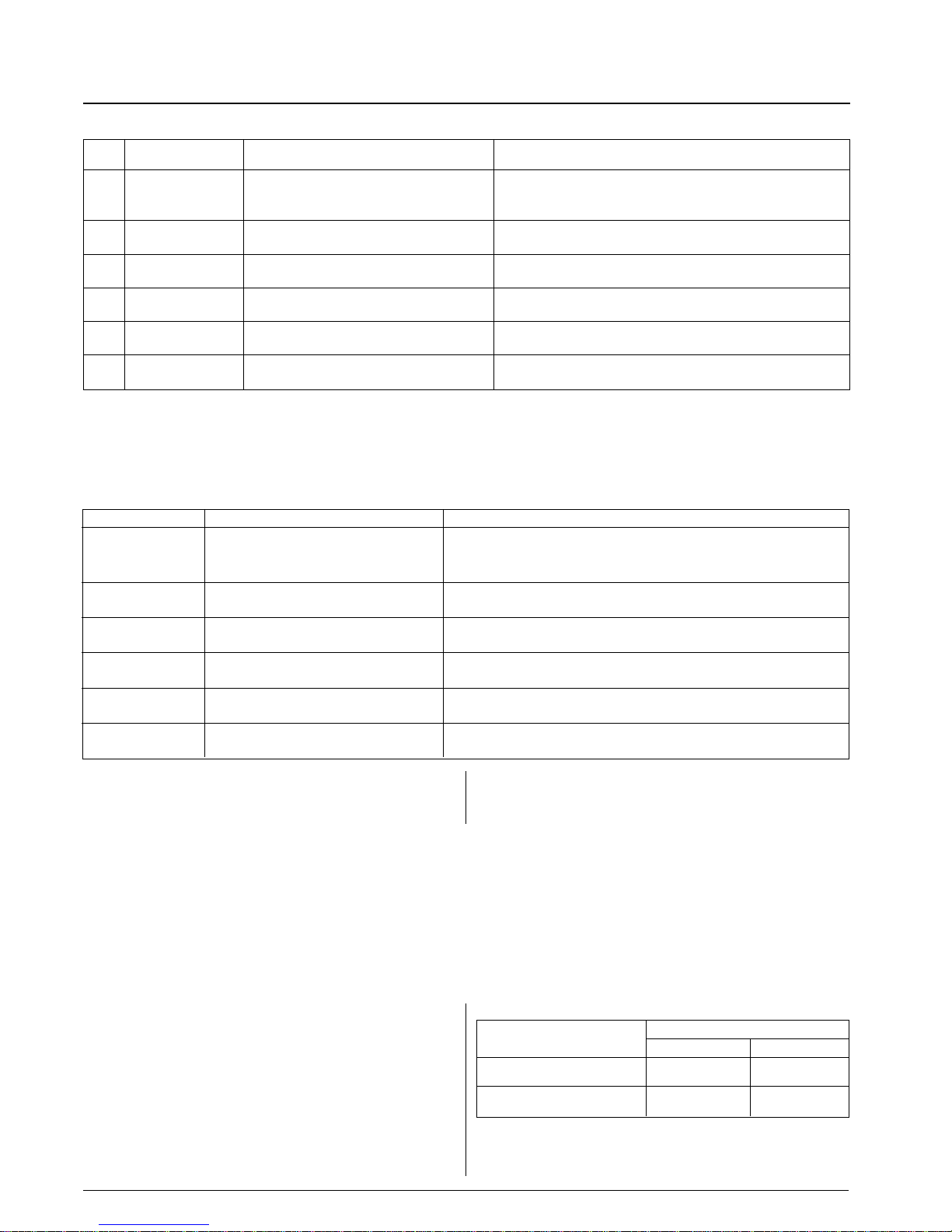
Table VIII : Accessories
Description
42PQV/38VBH
009 012
Wall bracket kit
••
Active carbon filter and
••
Passive electrostatic filter
Note:
If the “HR” is set to a value that is lower than “CR” and the remote
control operating mode is auto, the operating mode is set to
cooling.
Note:
If the selection is changed from “rc” (HP operation) to cooling only
and the remote control operating mode is auto or heating, the
operating mode is set to cool.
Table VI: Unit configuration
ITEM Shown on display Explanation Description
“A” remote unit A Remote address indoor unit A.
1 “rAdr”“b” remote unit B Remote address indoor unit B.
“Ab” remote unit A and b Default address both indoor unit.
2 “UCFG”
“HP” heat pump Default address is heat pump.
“AC” cooling only Change address for cooling only.
3 “UAdr” 1-
2
40 with increase of 1
CCN unit address.
Deafault=1
4 “ZONE” 1-
2
40 with increase of 1
Number of zone.
Deafault=0
5 “GFdn” 1-
2
40 with increase of 1
Number of GFD.
Deafault=1
6 “A St”
“OF”:unit in stop mode
Choose of operating mode after a power supply
interruption.
Unit configuration, remote configuration, guide for the owner and accessories
Note:
The selections of item 2, 3, 4 and 5 are not changeable in the unit even though remote control selections for these items are possible.
Table VII: Remote configuration
Shown on display Explanation description
“A”:unit A Address indoor unit A.
“CH”“b”:unit B Address indoor unit B.
“Ab”:unit A and B Default address is both indoor units.
“tU”
“C”:Degrees Celsius Temperature.
“F”:Degrees Fahrenheit Default is °C.
“rc”
“HP”:heat pump Default address is heat pump.
“AC”:cooling only Change address for cooling only.
“HR”
17-32:17°C~32°C Maximum heating setpoint in °C.
63-90:63°F~90°F Maximum heating setpoint in °F.
“CR”
17-32:17°C~32°C Minimum cooling setpoint °C.
63-90:63°F~90°F Minimum cooling setpoint °F.
“CL”
12:12hour clock (AM/PM) Time format (AM=morning; PM=afternoon).
24:24hour clock Default is 12.
Guide for the owner
When installation and tests are completed explain the Operation
and Maintenance Manual to the owner, with particular attention to
the main operating modes of the air conditioner, such as:
• Turning the unit on and off.
• Functions of the remote control.
• Removal and cleaning of the air filters.
Leave the installation manual with the owner for future use during
maintenance operations or for any other needs.
Page 22

42PQV/38VBH
GB - 21
ENGLISH
Maintenance and troubleshooting
• Mains voltage wrong (too high or too low).
• Condenser coil (outdoor or indoor, in case of heat pump
operation) obstructed; remove obstructions.
• Outdoor fan off; check cause and repair.
• Wrong indoor unit thermistors replace.
• Refrigerant circuit clogged; check and remove obstructions.
• Reversing valve faulty on heat pump models; replace.
• Expansion device clogged or covered with ice; drain refrigerant
(see note 1), evacuate and recharge.
Compressor runs continuously:
• Unit selected too small for actual air conditioning needs.
• Indoor temperature selection too low (if in cooling) or too high (if in
heating, for heat pump models); check temperature selection.
• Outdoor unit fan faulty; replace.
• Air or other non condensable gases in the circuit; drain refrigerant
(see note 1), evacuate and recharge.
• Obstructions at air intake or dirty indoor unit filters; remove
obstruction or clean filter.
Frequent ice build-up on outdoor coil (during heating with
heat pump units):
• Outdoor fan stopped; check cause and repair.
Discharge pressure too high:
• Outdoor coil dirty or obstructed; clean or remove obstructions.
• Condenser fan (outdoor or indoor, in case of heat pump
operation) faulty; replace.
• Indoor temperature selection too low in cooling or too high in
heating; check temperature selection.
• Air or other non-condensable gases in the circuit; drain
refrigerant (see note 1), evacuate and recharge.
Discharge pressure too low:
• Indoor temperature selection too high in cooling or too low in
heating; check temperature selection.
• Outdoor coil dirty or obstructed; clean or remove obstructions.
• Indoor unit air filter dirty; clean filter.
Suction pressure too high:
• Indoor temperature selection too low in cooling or too high in
heating; check temperature selection.
• Reversing valve (on heat pump models) faulty or internal leak;
replace.
Suction pressure too low:
• Indoor temperature selection too high in cooling or too low in
heating; check temperature selection.
• Evaporator coil (indoor or outdoor, in case of heat pump
models),covered with ice; see the following points.
• Air circulation on the evaporator unit (indoor or outdoor, in case
of heat pump models) not sufficient; check for the cause and
repair.
• Expansion device or suction line clogged: check and repair.
• Outdoor fan does not stop during defrost periods (when heating
with heat pump models); check electrical parts.
Outdoor fan cycling due to its overtemperature protection:
• Electrical connection loose; check connections.
• Fan motor burnt out; replace.
• Fan bearing seized; check and repair.
• Expansion device clogged or covered with ice; drain refrigerant
(see note 1), evacuate and recharge.
Note 1:
Do not release refrigerant to the atmosphere; use
refrigerant recovery equipment.
Troubleshooting
Compressor and fan of the outdoor unit will not start:
• Unit not energized; check the mains power connections.
• Main switch OFF; check and put to the ON position.
• Main switch fuses have blown; replace.
• Wait for 3 minutes; compressor cycling protection is on.
• Mains voltage too low.
• Electrical connections loose or wrong; check and repair.
Compressor will not start, but outdoor fan is running:
• Electrical connections of compressor loose or wrong; check and
repair.
• Compressor burnt out, seized or protection device on; check for
the cause and replace compressor if necessary.
Compressor starts, but stops due to its overtemperature
protection (other than stops caused by the normal operation
of the thermostat):
• Wrong refrigerant charge (excessive or low) or air or other non
condensable gases in the circuit; drain refrigerant (see note 1),
evacuate and recharge.
Unit maintenance
The following maintenance operations must be carried out by
qualified personnel.
Cleaning the coil
When necessary, proceed as follows for more careful cleaning of
the coil:
Switch the mains supply OFF.
Remove unit front panel complete with top cover by loosening
holding screws and lifting as shown.
Carefully clean the coil with a vacuum cleaner from inside to outside.
With the same vacuum cleaner, dust the inside of the fan
compartment and the fan blades.
Avoid any damage to the blades which may cause future vibrations
and noise.
Replace the unit front panel with cover and tighten the screws.
Page 23
42AP5A54030
Via R. Sanzio, 9 - 20058 Villasanta (MI) Italy - Tel. 039/3636.1
The manufacturer reserves the right to change any product specifications without notice.
Order No. 14487, December 2002. Supersedes Order No.(New). Printed in Korea
 Loading...