

Page 1
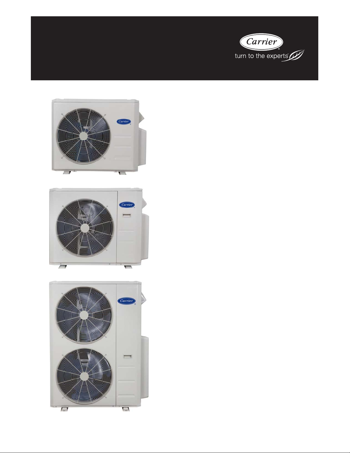
38MGR
Multi-zone Outdoor Unit Ductless System
Sizes 18, 24, 30, 36 and 48
Product Data
Fig. 1 − 18K
Fig. 2 − 24K and 30K
INDUSTRY LEADING
FEATURES / BENEFITS
A competitively priced and creative solution to
design problems.
The 38MGR ductless inverter driven multi−zone system provides
individual comfort control for up to 5 separate zones. Two, three,
four or five space−saving High Wall, Cassette, Ducted Style or
Floor Console fan coils can be matched with one outdoor heat
pump. The indoor fan coils are connected to the outdoor unit by
refrigerant tubing and wires.
The different styles of indoor units can be mounted in several
locations to accommodate the application. This selection of fan
coils permits inexpensive and creative solutions to design problems
such as:
S When adding air conditioning to spaces that are heated by
hydronic or electric heat and have no ductwork.
S Historical renovations or any application where preserving the
look of the original structure is essential.
S Commercial add−on jobs where the existing air conditioning
system cannot be stretched.
These compact indoor fan coil units take up very little space in the
room and do not obstruct windows. The fan coils are attractively
styled to blend with most room decors.
Advanced system components incorporate innovative technology
to provide reliable cooling and heating performance at low sound
levels.
Fig. 3 − 36K and 48K
NOTE: Images for illustration purposes only. Actual models may be slightly
different.
Page 2

Inverter Technology
The inverter driven compressor is designed to run at various input
power frequencies (Hz) which controls the compressor’s motor
speed.
Even Temperature – The control package, including the inverter,
monitors the outdoor and indoor temperatures as they relate to the
selected indoor set point and adjusts the compressor speed to match
the load and keep the system operating continuously rather than
cycling and creating temperature swings. This translates to higher
comfort levels for the occupants.
Rapid Pull Down/Warm−Up – Comfort is increased by the
inverter system’s ability to ramp up the compressor speed enabling
the system to reach the user selected room temperature set point
quicker.
Humidity Control – Running the system for longer periods and
continuously varying the compressor speed enhances the humidity
control.
Individual Room Comfort
Maximum comfort is provided because each space can be
controlled individually based on the usage pattern.
Low Sound Levels
When noise is a concern, ductless systems are the answer. The
indoor units are whisper quiet. There are no compressors indoors,
either in the conditioned space or directly over it, and there is none
of the noise usually generated by air being forced through the
ductwork.
When sound ordinances and proximity to neighbors demand quiet
operation, the 38MGR unit is the right choice. With the inverter
technology, these units run at lower speeds most of the time
resulting in reduced sound levels.
Inverter Technology – Enhanced Economical Operation
Ductless systems are inherently economical to operate. Individual
rooms are heated or cooled only when required, and since the air is
delivered directly to the space, there is no need to use additional
energy to move the air in the ductwork. This economical operation
is enhanced further when the inverter system output matches the
load resulting in a more efficient system.
Easy−To−Use Controls
The multi−zone systems have microprocessor−based controls to
provide the ultimate in comfort and efficiency. The user friendly
wired and wireless remote controls provide the interface between
the user and the unit.
Secure Operation
If security is an issue, outdoor and indoor units are connected only
by refrigerant piping and wiring to prevent intruders from crawling
through ductwork or wall openings. In addition, since the 38MGR
can be installed close to an outside wall, coils are protected from
vandals and severe weather.
Fast Installation
This compact ductless system is simple to install. A mounting
bracket is included with the indoor units and only wires and piping
need to run between the indoor and outdoor units. These units are
fast and easy to install ensuring minimal disruption to customers in
homes or the workplace. This makes the 38MGR systems the
equipment of choice for retrofit applications.
Simple Servicing and Maintenance
Removing the top panel of the outdoor unit provides immediate
access to the control compartment, providing the service technician
access to the diagnostic LEDs to facilitate the troubleshooting
process. In addition, the draw−thru design of the outdoor unit
means that dirt accumulates on the outside surface of the coil. Coils
can be cleaned quickly from the inside using a pressure hose and
detergent.
On the indoor units, service and maintenance expense is reduced
due to the permanent easy to clean filters. Also, error codes are
displayed on the front panel to alert the user to certain system
malfunctions
Built−in Reliability
Ductless system indoor and outdoor units are designed to provide
years of trouble−free operation.
Both the indoor and outdoor units are well protected. Whenever
the microprocessor detects abnormal conditions, the unit stops and
an error code appears.
Inverter systems provide additional reliability due to the soft start.
This refers to the ability of the inverter to start the compressor
motor using reduced voltage and reduced current. This feature is
beneficial from an electrical standpoint (eliminates current spikes)
as well as an overall reliability standpoint due to reduced stress on
all associated system components.
Agency Listings
All systems are listed with AHRI (Air conditioning, Heating, and
Refrigeration Institute) and are ETL certified per UL 1995
standard.
2
Page 3
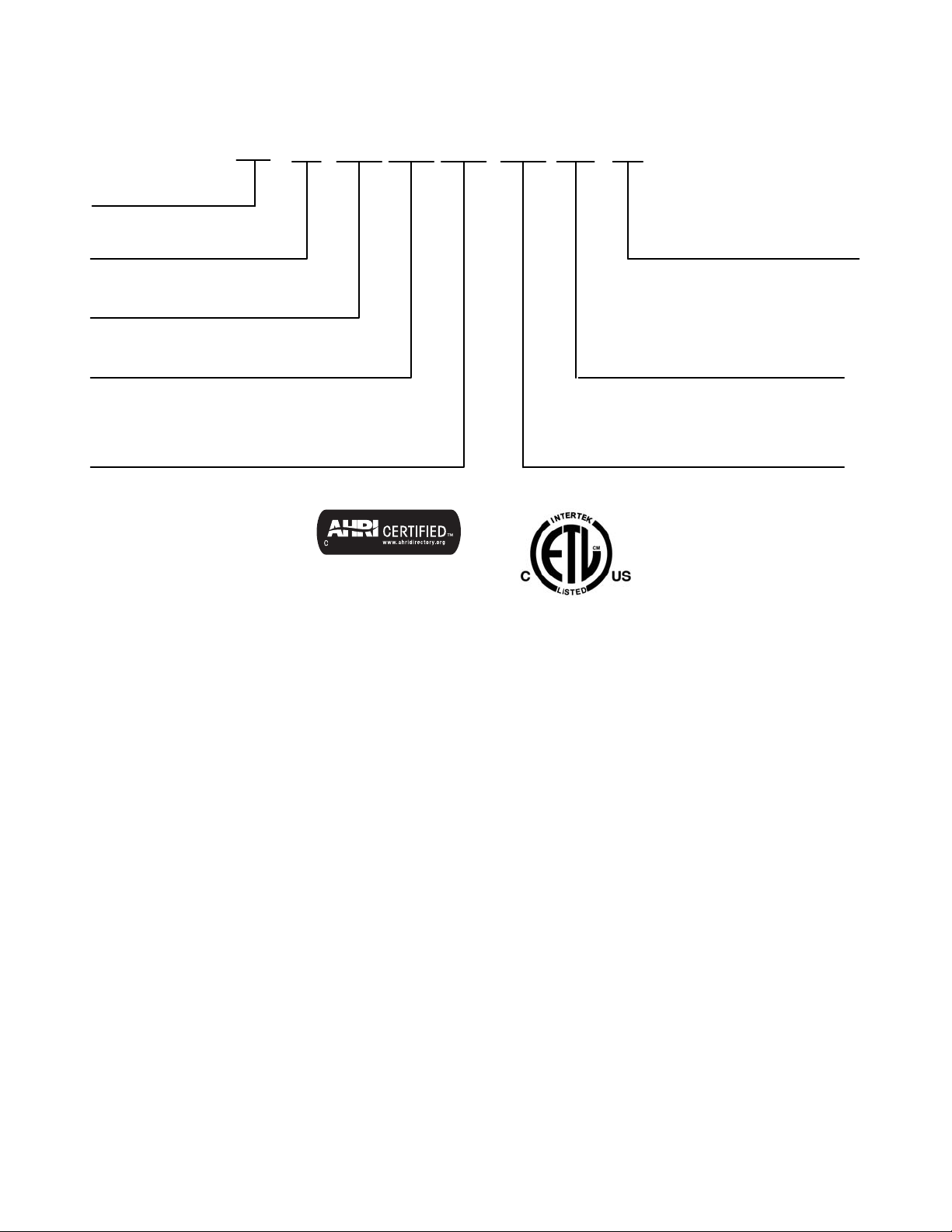
MODEL NUMBER NOMENCLATURE
OUTDOOR UNIT
38 = OUTDOOR UNIT
MG = ALL
UNIT TYPE
R = OUTDOOR UNIT
SYSTEM TYPE
Q = HEAT PUMP
NOMINAL CAPACITY
18 - 1 1/2 TONS
24 - 2 TONS
30 - 21/2 TONS
36 - 3 TONS
48 - 4 TONS
38 MG 318
Use of the AHRI Certified
TM Mark indicates a
manufacturer’s
participation in the
program For verification
of certification for individual
products, go to
www.ahridirectory.org.
QRB
- -
VOLTAGE
3 = 208/230-1-60
NOT USED
MAXIMUM NUMBER OF FAN COIL UNITS THAT
CAN BE CONNECTED TO THE OUTDOOR UNIT
B = 1:2
C = 1:3
D = 1:4
E = 1:5
3
Page 4

STANDARD FEATURES AND ACCESSORIES
Ease of Installation
Low Voltage Controls S
Comfort Features
Microprocessor Control S
Auto Restart Function S
Auto Changeover S
Energy Saving Features
Inverter Driven Compressor S
46° F Heating Mode (Heating Setback) S
Safety And Reliability
3 Minute Time Delay For Compressor S
High Compressor Discharge Temperature S
Low Voltage Protection S
Compressor Overload Protection S
Compressor Over Current Protection S
IPM Module Protection S
Aluminum Blue Hydrophilic pre-coated fins S
Ease of Service
Diagnostic S
Error Messages Displayed On Front Panel S
Application Flexibility
Crankcase Heater S
Basepan Heater S
Legend
S Standard
A Accessory
Outdoor Units
Crankcase Heater
The crankcase heater is standard on all unit sizes. Heater clamps
must be placed around the compressor oil stump.
Base pan Heater
The base pan heater is standard on all unit sizes.
4
Page 5
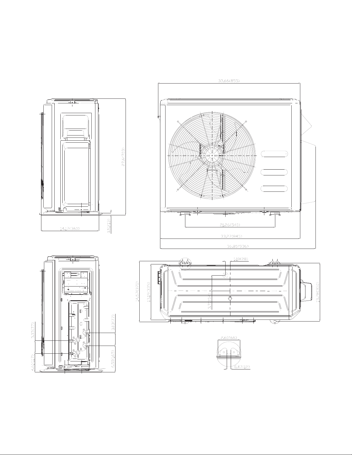
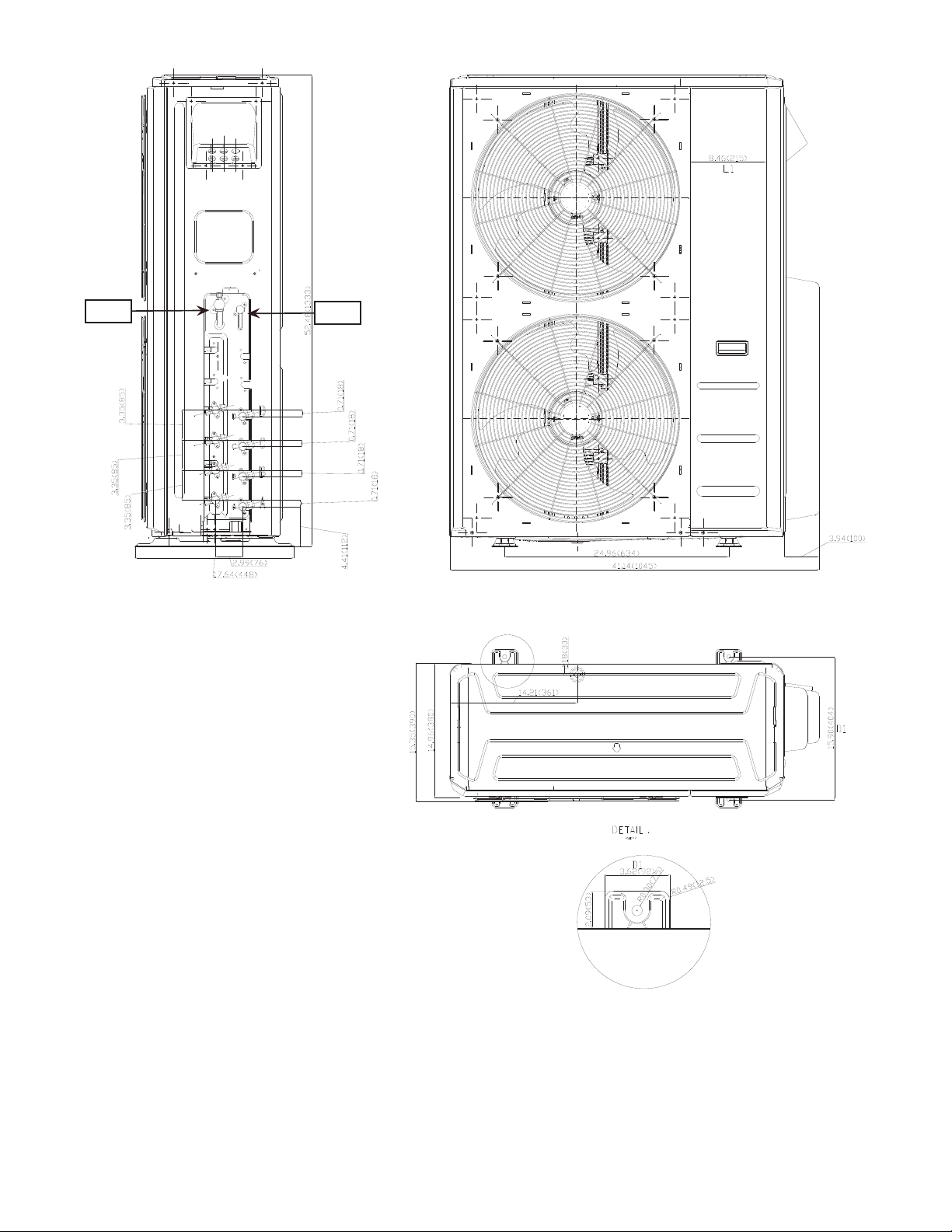
DIMENSIONS − OUTDOOR
UNIT SIZE 18 24 30 36 48
Height in (mm) 27.6 (703) 31.89 (810) 31.89 (810) 52.48 (1333) 52.48 (1333)
Width in (mm) 33.27 (845) 37.24 (946) 37.24 (946) 41.14 (1045) 41.14 (1045)
Depth in (mm) 13.19 (335) 15.20 (386) 15.20 (386) 14.96 (380) 14.96 (380)
Weight-Net lbs (kg) 105.8 (48) 149.9 (68) 156.5 (71) 223.8 (101.5) 223.8 (101.5)
Fig. 4 − Outdoor Dimensions Size 18
NOTE: Master valves are not available on the size 18 unit.
5
Page 6
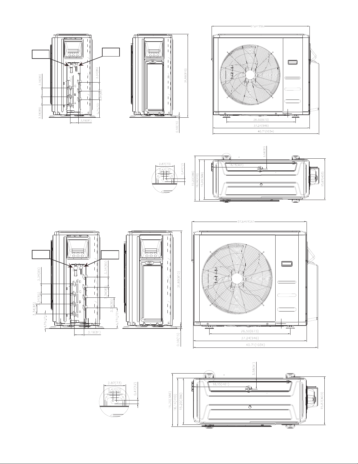
DIMENSIONS − OUTDOOR (CONTINUED)
Master Valve
Liquid Line
Master Valve
Suction Line
Fig. 5 − Outdoor Dimensions Size 24
Master Valve
Liquid Line
Master Valve
Suction Line
Fig. 6 − Outdoor Dimensions Size 30
6
Page 7
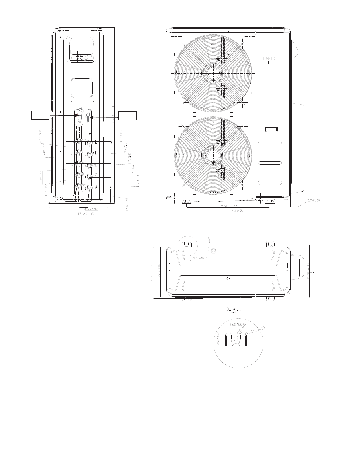
DIMENSIONS − OUTDOOR (CONTINUED)
Master Valve
Liquid Line
Master Valve
Suction Line
Fig. 7 − Outdoor Dimensions Size 36
7
Page 8
DIMENSIONS − OUTDOOR (CONTINUED)
Master Valve
Liquid Line
Master Valve
Suction Line
Fig. 8 − Outdoor Dimensions Size 48
8
Page 9
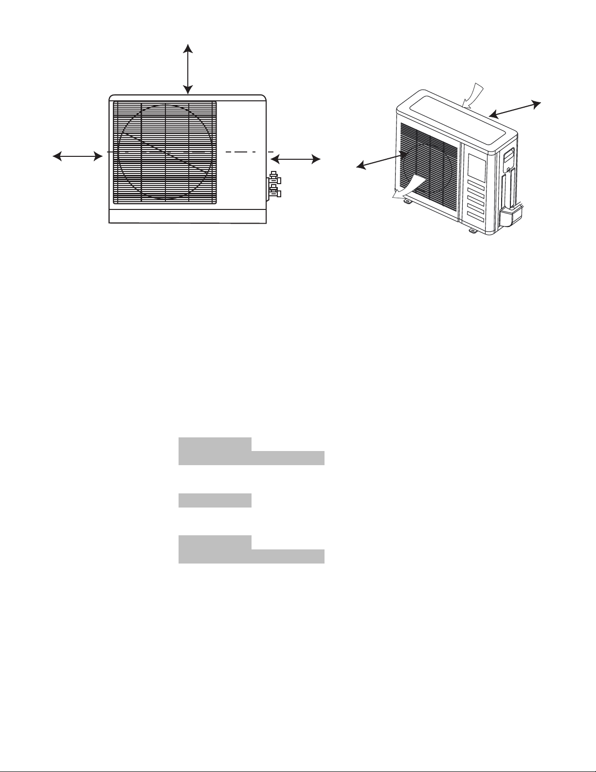
CLEARANCES − OUTDOOR
D
A
B
C
Air-outlet
Fig. 9 − Clearances Outdoor
UNIT
A 24 (609)
B 24 (609)
C 24 (609)
D 4 (101)
E 6 (152)
MINIMUM VALUE
in. (mm)
Air-inlet
E
NOTE: Outdoor Unit must be mounted at least 2in (50mm) above the maximum anticipated snow depth.
COMPATIBILITY TABLE
INDOOR UNIT
High Wall
Cassette
Ducted
Floor
Console
40MAQB09B--3
40MAQB12B--3
40MAQB18B--3
40MAQB24B--3
40MBQB09C--3
40MBQB12C--3
40MBQB18C--3
40MBQB09D--3
40MBQB12D--3
40MBQB18D--3
40MBQB24D--3
40MBQB09F--3
40MBQB12F--3
38MGRQ18B--3 38MGRQ24C--3 38MGRQ30D--3 38MGRQ36D--3 38MGRQ48E--3
• • • • •
• • • • •
• • • •
• • • • •
• • • • •
• • • •
• • • • •
• • • • •
• • • •
• • • • •
• • • • •
OUTDOOR UNIT
• • •
• • •
9
Page 10

PHYSICAL DATA − OUTDOOR
System
Per form ance
Non-Ducted
Per form ance
Combination
Ducted
and
Non-Ducted
Per form ance
Ducted
Operating
Range
Piping
Refrigerant
Electrical
Compressor
Outdoor
Size 18 24 30 36 48
Outdoor Model 38MGRQ18B--3 38MGRQ24C--3 38MGRQ30D--3 38MGRQ36D--3 38MGRQ48E--3
Max Number of Zones 2 3 4 4 5
Energy Star YES YES YES YES YES
Cooling System Tons 1.5 2.0 2.5 3.0 4.0
Cooling Rated Capacity Btu/h 18,000 24,000 30,000 36,000 48,000
Cooling Cap. Range Min - Max Btu/h 5810~ 21940 7880~ 33510 8090~ 41470 8560~ 45020 8560~ 53160
SEER 22.5 23 23.8 21.5 22.4
EER 12.5 12.5 12.5 13.5 12.5
Heating Rated Capacity (47° F) Btu/h 19,000 23,000 28,000 36,000 48,000
Heating Rated Capacity (17° F) Btu/h 12,000 13,600 17,400 23,200 29,600
Heating Maximum Capacity (5° F) Btu/h 13,900 23,000 28,000 36,000 36,000
Heating Cap. Range Min - Max Btu/h 5760~ 24480 6010~ 36180 6350~ 41950 7210~ 50350 7210~ 55820
HSPF 10.3 9.8 10.0 10.5 10.2
COP (47° F) W/W 3.6 3.9 3.8 3.8 3.6
COP (17° F) W/W 2.8 2.7 2.8 2.8 2.7
COP (5° F) W/W 2.2 2.1 2.0 1.8 2.0
Energy Star NO YES NO NO NO
Cooling System Tons 1.5 1.9 2.4 3.0 4.0
Cooling Rated Capacity Btu/h 18,000 23,000 29,000 35,500 48,000
Cooling Cap. Range Min - Max Btu/h 5795~ 20708 7765~ 31955 8060~ 39990 8510~ 42635 8510~ 52580
SEER 20.45 21 21.65 19.25 20
EER 12.15 12.5 12 12.15 11.3
Heating Rated Capacity (47° F) Btu/h 18,750 22,000 28,000 36,000 49,000
Heating Rated Capacity (17° F) Btu/h 11,700 12,900 17,300 23,800 31,300
Heating Maximum Capacity (5° F) Btu/h 14,150 22,000 28,000 35,500 36,400
Heating Cap. Range Min - Max Btu/h 5650~ 24365 5980~ 36190 6275~ 42305 7045~ 47800 7045~ 54935
HSPF 9.9 9.3 9.5 9.9 10.2
COP (47° F) W/W 3.7 3.9 3.7 3.7 3.5
COP (17° F) W/W 2.7 2.6 2.7 2.7 2.7
COP (5° F) W/W 2.1 2.0 2.0 1.8 1.9
Energy Star NO YES NO NO NO
Cooling System Tons 1.5 1.8 2.3 2.9 4.0
Cooling Rated Capacity Btu/h 18,000 22,000 28,000 35,000 48,000
Cooling Cap. Range Min - Max Btu/h 5780~ 19476 7650~ 30400 8030~ 38510 8460~ 40250 8460~ 52000
SEER 18.4 19 19.5 17 17.6
EER 11.8 12.5 11.5 10.8 10.1
Heating Rated Capacity (47° F) Btu/h 18,500 21,000 28,000 36,000 50,000
Heating Rated Capacity (17° F) Btu/h 11,400 12,200 17,200 24,400 33,000
Heating Maximum Capacity (5° F) Btu/h 14,400 21,000 28,000 35,000 36,800
Heating Cap. Range Min - Max Btu/h 5539~ 24249 5950~ 36200 6200~ 42660 6880~ 45250 6880~ 54050
HSPF 9.4 8.8 9.0 9.2 10.1
COP (47° F) W/W 3.8 3.8 3.6 3.6 3.4
COP (17° F) W/W 2.7 2.5 2.5 2.5 2.6
COP (5° F) W/W 2.1 2.0 2.0 1.7 1.8
Cooling Outdoor DB Min - Max °F(°C)
Heating Outdoor DB Min - Max °F(°C)
Total Piping Length ft (m) 131(40) 197(60) 263(80) 328(100) 328(100)
Piping to furthest FCU ft (m) 82 (25) 98 (30) 115(35) 115(35) 115 (35)
Drop (OD above ID) ft (m) 49(15) 49(15) 49(15) 65(20) 65(20)
Lift (OD below ID) ft (m) 49(15) 49(15) 49(15) 65(20) 65(20)
Pipe Connection Size - Liquid in (mm)
Pipe Connection Size - Suction in (mm)
Ty pe R410A R410A R410A R410A R410A
Charge lbs (kg) 4.41 (2.0) 6.17(2.8) 6.61 (3.0) 10.13 (4.6) 10.13 (4.6)
Metering Device EEV EEV EEV EEV EEV
Voltage, Phase, Cycle V/Ph/Hz 208/230-1-60 208/230-1-60 208/230-1-60 208/230-1-60 208/230-1-60
Power Supply Indoor unit powered from outdoor unit
MCA A. 18 25 30 35 35
MOCP - Fuse Rating A. 25 35 45 50 50
Ty pe Rotary Inverter Rotary Inverter Rotary Inverter Rotary Inverter Rotary Inverter
Model ATM150D23UFZ ATF235D22UMT ATF310D43UMT ATQ360D1UMU ATQ360D1UMU
Oil Type ESTER OIL VG74 ESTER OIL VG74 ESTER OIL VG74 ESTER OIL VG74 ESTER OIL VG74
Oil Charge Fl. Oz. 17.64 23.58 35.27 49.38 49.38
Rated Current RLA 10 15 19 21 21
Unit Width in (mm) 37.31 (948) 41.22 (1047) 41.22 (1047) 41.15 (1045) 41.15 (1045)
Unit Height in (mm) 27.64 (702) 31.88 (810) 31.88 (810) 52.48 (1333) 52.48 (1333)
Unit Depth in (mm) 14.82 (376) 17.91 (455) 17.91 (455) 17.63 (448) 17.63 (448)
Net Weight lbs (kg) 105.8 (48) 149.9 (68) 156.5 (71) 221.6 (100.5) 223.8 (101.5)
Airflow CFM 1,390 2,130 2,130 4,500 4,500
Sound Pressure dB(A) 62 63 62 64 64
-13~ 122
(-25~ 50)
-22~ 86
(-30~ 30)
1/4*2
(6.35*2)
3/8*2
(9.52*2)
HEAT PUMP
-13~ 122
(-25~ 50)
-22~ 86
(-30~ 30)
(6.35*3)
(9.52*3)
1/4*3
3/8*3
-13~ 122
(-25~ 50)
-22~ 86
(-30~ 30)
1/4*4
(6.35*4)
1/2 *1+ 3/8*3
(12.7*1+9.52*3)
-13~ 122
(-25~ 50)
-22~ 86
(-30~ 30)
1/4*4
(6.35*4)
1/2 *1+ 3/8*3
(12.7*1+9.52*3)
-13~ 122
(-25~ 50)
-22~ 86
(-30~ 30)
1/4*5
(6.35*5)
1/2 *2+ 3/8*3
(12.7*2+9.52*3)
10
Page 11

COOLING PERFORMANCE NON−DUCTED COMBINATIONS
MODEL
18
24
30
36
48
Indoor Conditions -13F
69.8F
(21C)
75.2F
(24C)
80.6F
(27C)
89.6F
(32C)
69.8F
(21C)
75.2F
(24C)
80.6F
(27C)
89.6F
(32C)
69.8F
(21C)
75.2F
(24C)
80.6F
(27C)
89.6F
(32C)
69.8F
(21C)
75.2F
(24C)
80.6F
(27C)
89.6F
(32C)
69.8F
(21C)
75.2F
(24C)
80.6F
(27C)
89.6F
(32C)
COOLING OUTDOOR CONDITIONS (DB)
DB WB
59F
(15C)
62.6F
(17C)
66.2F
(19C)
73.4F
(23C)
59F
(15C)
62.6F
(17C)
66.2F
(19C)
73.4F
(23C)
59F
(15C)
62.6F
(17C)
66.2F
(19C)
73.4F
(23C)
59F
(15C)
62.6F
(17C)
66.2F
(19C)
73.4F
(23C)
59F
(15C)
62.6F
(17C)
66.2F
(19C)
73.4F
(23C)
(-25C)
TC 19.12 19.86 19.66 19.26 18.87 20.69 21.78 19.94 17.92 12.00 11.58 9.89
SC 15.11 15.49 15.34 15.03 14.72 16.14 17.00 15.95 15.23 12.00 11.58 9.89
Input 1.37 1.41 1.48 1.53 1.57 1.60 1.63 1.79 1.96 1.47 1.52 1.32
TC 20.54 21.45 21.23 20.81 20.38 22.35 23.52 21.54 19.35 12.96 12.51 10.13
SC 15.35 15.61 15.29 15.40 15.28 16.98 18.35 17.01 15.87 11.53 11.88 9.93
Input 1.40 1.46 1.53 1.58 1.62 1.65 1.68 1.84 2.01 1.50 1.54 1.35
TC 21.91 22.46 22.18 22.53 22.85 24.15 25.11 23.85 21.54 14.82 14.22 10.40
SC 16.44 16.85 16.64 18.05 17.14 18.11 18.33 17.89 16.16 14.52 14.08 10.40
Input 1.41 1.45 1.51 1.58 1.62 1.65 1.68 1.88 2.05 1.52 1.57 1.36
TC 23.89 24.48 24.18 24.56 24.91 26.32 27.37 26.00 23.48 16.15 15.50 11.34
SC 17.20 17.63 17.65 18.17 18.68 19.22 22.44 21.84 20.19 15.18 14.88 11.11
Input 1.46 1.50 1.56 1.63 1.67 1.72 1.73 1.93 2.14 1.57 1.62 1.41
TC 31.96 32.76 32.58 32.60 32.15 32.75 32.44 26.94 24.46 19.98 17.56 15.45
SC 22.38 22.94 22.81 22.82 22.51 22.93 25.47 22.82 21.70 19.42 17.21 15.45
Input 2.26 2.32 2.31 2.34 2.36 2.38 2.41 2.26 2.50 2.39 2.58 2.62
TC 34.53 35.39 35.19 35.21 34.72 35.37 35.04 29.10 26.42 21.58 18.96 16.69
SC 24.17 24.77 24.63 24.65 24.31 24.76 26.28 23.86 22.72 19.42 18.02 16.52
Input 2.30 2.36 2.35 2.38 2.40 2.42 2.45 2.30 2.54 2.43 2.60 2.66
TC 36.25 37.15 37.24 37.08 37.51 37.68 37.53 35.39 32.75 24.71 23.96 20.15
SC 25.38 26.01 26.07 25.96 26.26 26.38 26.95 26.08 25.06 22.09 23.84 20.05
Input 2.20 2.25 2.28 2.34 2.35 2.41 2.47 2.75 3.04 2.48 2.62 2.74
TC 38.78 39.75 39.85 39.68 40.14 40.32 40.16 37.87 35.04 26.44 25.64 21.56
SC 27.15 27.83 27.89 27.77 28.09 30.64 32.93 32.19 31.19 24.32 24.61 21.56
Input 2.26 2.32 2.35 2.38 2.42 2.48 2.54 2.82 3.11 2.55 2.69 2.81
TC 39.15 40.12 40.28 39.54 39.18 40.81 39.79 37.98 36.16 28.21 26.56 23.46
SC 27.40 28.08 28.20 27.68 27.43 30.61 31.57 30.73 29.86 26.40 26.18 23.12
Input 3.08 3.16 3.18 3.12 3.21 3.24 3.28 3.62 3.99 3.13 3.25 2.66
TC 40.32 41.32 41.49 40.73 40.36 42.03 41.38 41.02 39.05 30.47 28.68 25.34
SC 28.23 28.93 29.04 28.51 28.25 31.53 33.93 36.10 35.15 28.03 27.25 24.83
Input 3.13 3.21 3.23 3.17 3.26 3.29 3.33 3.67 4.04 3.18 3.30 2.71
TC 41.13 42.15 42.51 42.61 42.10 42.61 42.41 40.63 38.82 32.17 30.47 27.53
SC 28.79 29.51 29.76 29.83 29.47 31.96 32.30 31.45 30.57 28.30 30.18 27.25
Input 3.13 3.21 3.25 3.29 3.31 3.38 3.42 3.67 4.05 3.21 3.31 2.76
TC 44.41 45.52 45.91 46.02 45.47 46.02 45.80 43.88 41.93 34.74 32.91 29.73
SC 31.10 31.87 32.14 32.21 31.83 34.51 37.56 38.61 37.73 31.96 31.26 29.73
Input 3.19 3.27 3.31 3.35 3.37 3.44 3.48 3.73 4.11 3.27 3.37 2.82
TC 37.82 38.76 38.32 39.02 39.41 40.44 40.91 36.89 33.97 27.85 25.60 23.33
SC 26.47 27.13 26.82 27.31 28.38 30.33 31.91 30.25 28.88 24.50 23.55 22.40
Input 2.69 2.76 2.83 2.87 2.91 2.98 3.03 3.39 3.79 3.68 3.76 3.41
TC 38.96 39.93 39.47 40.19 40.59 41.65 42.54 39.84 36.69 30.07 27.65 25.20
SC 27.27 27.95 27.63 28.13 28.42 31.24 34.88 35.06 33.02 27.67 26.26 24.69
Input 2.74 2.81 2.88 2.92 2.96 3.03 3.08 3.44 3.84 3.73 3.81 3.46
TC 42.58 43.64 43.31 44.15 44.54 45.02 45.94 43.73 41.49 34.44 31.93 27.16
SC 29.81 30.55 30.32 30.91 31.18 33.77 35.83 34.99 35.26 31.00 30.33 26.62
Input 2.79 2.86 2.89 2.91 2.95 3.06 3.10 3.48 3.91 3.80 3.85 3.47
TC 45.98 47.13 46.78 47.68 48.10 48.63 49.61 47.23 44.80 37.20 34.48 29.34
SC 32.19 32.99 32.74 33.38 33.67 36.47 40.68 41.56 40.32 34.22 32.76 29.34
Input 2.85 2.92 2.95 2.97 3.01 3.12 3.16 3.54 3.97 3.86 3.91 3.53
TC 41.22 42.25 42.51 41.87 41.24 41.97 41.47 39.32 36.26 32.97 29.86 26.54
SC 28.86 29.58 29.76 29.31 28.87 30.64 37.24 36.86 35.53 32.97 29.86 26.54
Input 2.19 2.24 2.28 2.35 2.38 2.41 2.46 2.78 3.11 3.45 3.64 3.08
TC 44.52 45.63 45.91 45.22 44.54 45.33 44.79 42.47 39.16 35.61 32.25 28.66
SC 32.50 33.31 33.51 33.01 32.51 34.90 37.17 36.10 34.07 32.05 32.25 28.66
Input 2.25 2.31 2.35 2.42 2.45 2.48 2.53 2.85 3.18 3.52 3.71 3.15
TC 53.80 55.14 54.68 55.31 56.15 56.72 60.26 56.82 53.16 40.95 38.57 35.24
SC 40.35 41.36 41.01 42.12 42.11 42.54 46.04 44.49 42.79 37.95 38.57 35.24
Input 2.99 3.06 3.15 3.25 3.29 3.46 3.94 4.36 4.80 3.79 3.98 3.43
TC 56.49 57.90 57.41 58.08 58.96 59.56 63.27 59.66 55.82 43.00 40.50 37.04
SC 41.80 42.84 42.49 42.98 43.63 46.45 52.52 51.31 50.24 40.85 40.50 37.04
Input 3.05 3.13 3.22 3.32 3.36 3.53 4.01 4.43 4.87 3.86 4.05 3.50
-4F
(-20C)0F(-17C)5F(-15C)
17F
(-8C)
47F
(8C)
77F
(25C)
86F
(30C)
95F
(35C)
104F
(40C)
113F
(45C)
122F
(50C)
LEGEND
DB - Dry Bulb
WB - Wet Bulb
TC - Total Net Cooling Capacity (1000 Btu/hour)
SC - Sensible Capacity (1000 Btu/hour)
Input - Total Power (kW)
11
Page 12

HEATING PERFORMANCE NON−DUCTED COMBINATIONS
MODEL
18
24
30
36
48
Indoor Conditions DB
HEATING OUTDOOR CONDITIONS (DB)
59F
(15C)
64.4F
(18C)
69F
(20.5C)
71.6F
(22C)
59F
(15C)
64.4F
(18C)
69F
(20.5C)
71.6F
(22C)
59F
(15C)
64.4F
(18C)
69F
(20.5C)
71.6F
(22C)
59F
(15C)
64.4F
(18C)
69F
(20.5C)
71.6F
(22C)
59F
(15C)
64.4F
(18C)
69F
(20.5C)
71.6F
(22C)
Input 1.67 1.71 1.76 1.80 1.87 1.93 1.95 2.01 1.60 1.66 1.79 1.87
COP 1.36 1.64 1.93 2.04 2.19 2.92 2.92 3.00 3.80 3.83 4.21 4.28
Input 1.70 1.74 1.79 1.83 1.90 1.96 1.98 2.04 1.63 1.69 1.82 1.90
COP 1.31 1.58 1.87 1.98 2.16 2.83 2.84 2.91 3.67 3.70 4.10 4.16
Input 1.41 1.44 1.46 1.47 1.91 1.63 1.68 1.76 1.80 1.88 1.95 1.97
COP 1.15 1.33 1.54 1.62 2.15 2.70 2.78 2.85 3.08 3.05 3.59 3.96
Input 1.44 1.47 1.49 1.50 2.01 1.66 1.71 1.79 1.83 1.91 1.98 2.00
COP 1.19 1.28 1.49 1.57 1.99 2.61 2.69 2.76 2.99 2.97 3.49 3.85
Input 2.93 3.19 3.23 3.45 3.63 2.66 2.79 2.87 2.65 2.78 2.96 2.71
COP 1.41 1.65 1.84 1.93 1.98 2.83 2.74 2.89 3.37 3.40 3.65 4.43
Input 3.00 3.27 3.31 3.53 3.74 2.73 2.86 2.94 2.72 2.89 2.99 2.74
COP 1.36 1.59 1.77 1.86 1.91 2.73 2.64 2.79 3.25 3.23 3.56 4.31
Input 3.07 3.34 3.38 3.61 3.90 2.79 2.92 3.01 2.77 2.96 3.04 3.17
COP 1.32 1.54 1.72 1.81 1.81 2.65 2.56 2.71 3.16 3.09 3.49 3.76
Input 3.14 3.42 3.46 3.70 3.83 2.85 2.99 3.08 2.84 3.01 3.07 3.20
COP 1.29 1.50 1.67 1.76 1.80 2.57 2.49 2.63 3.07 3.00 3.41 3.67
Input 3.39 3.46 3.45 3.62 3.74 3.71 3.73 3.79 3.08 3.12 3.27 3.37
COP 1.61 1.91 2.08 2.17 2.29 2.51 2.52 2.59 3.34 3.48 3.45 3.64
Input 3.42 3.49 3.53 3.75 3.86 3.84 3.86 3.92 3.11 3.15 3.30 3.40
COP 1.58 1.87 2.01 2.07 2.18 2.39 2.40 2.47 3.26 3.40 3.37 3.56
Input 3.51 3.58 3.64 3.76 4.05 3.85 3.90 4.04 3.14 3.18 3.21 3.30
COP 1.39 1.69 1.78 1.87 2.04 2.11 2.11 2.31 3.17 3.33 3.40 3.58
Input 3.64 3.61 3.77 3.79 3.81 3.88 3.93 4.07 3.17 3.21 3.24 3.33
COP 1.25 1.58 1.69 1.84 2.00 2.06 2.07 2.26 3.09 3.24 3.32 3.49
Input 4.91 5.02 5.17 5.20 5.24 5.11 5.13 5.21 4.56 4.73 4.90 4.56
COP 1.42 1.67 1.74 1.89 2.05 2.25 2.28 2.31 2.77 2.84 3.40 4.04
Input 4.97 5.08 5.23 5.26 5.33 5.17 5.19 5.27 4.62 4.79 4.96 4.62
COP 1.39 1.63 1.70 1.85 2.00 2.19 2.22 2.25 2.70 2.76 3.31 3.93
Input 5.04 5.15 5.24 5.27 5.39 5.25 5.27 5.35 4.62 4.96 4.66 4.30
COP 1.34 1.58 1.62 1.77 1.96 2.09 2.10 2.18 2.69 2.74 3.18 3.71
Input 5.09 5.20 5.29 5.32 5.34 5.30 5.32 5.40 4.67 5.01 4.71 4.35
COP 1.30 1.53 1.58 1.72 1.90 2.03 2.04 2.11 2.61 2.66 3.08 3.59
Input 4.96 5.07 5.22 5.25 5.33 5.16 5.18 5.26 4.61 4.78 4.95 4.61
COP 1.42 1.67 1.74 1.89 2.05 2.24 2.27 2.31 2.76 2.83 3.39 4.31
Input 5.07 5.18 5.33 5.37 5.51 5.27 5.29 5.38 4.71 4.89 5.06 4.71
COP 1.37 1.61 1.68 1.83 1.98 2.17 2.19 2.23 2.66 2.73 3.27 4.15
Input 5.10 5.21 5.30 5.33 5.39 5.31 5.33 5.41 4.68 4.63 4.71 5.04
COP 1.34 1.58 1.63 1.77 1.96 2.09 2.10 2.18 2.69 2.98 3.47 3.82
Input 5.15 5.26 5.35 5.38 5.40 5.36 5.38 5.46 4.73 5.07 4.76 5.09
COP 1.30 1.53 1.58 1.72 1.90 2.03 2.04 2.11 2.60 2.66 3.37 3.71
-22F
-13F
(-30C)
(-25C)
TC 7.74 9.54 11.60 12.54 14.40 19.21 19.46 20.59 20.74 21.67 25.82 27.35
TC 7.63 9.40 11.43 12.35 14.01 18.92 19.17 20.28 20.43 21.34 25.43 26.94
TC 5.52 6.54 7.69 8.14 13.99 15.02 15.94 17.13 18.93 19.66 23.96 26.67
TC 5.84 6.44 7.57 8.02 13.65 14.79 15.70 16.87 18.65 19.37 23.60 26.27
TC 14.13 17.95 20.25 22.73 24.45 25.66 26.04 28.31 30.43 32.22 36.92 40.88
TC 13.95 17.73 20.00 22.45 24.35 25.34 25.72 27.96 30.12 31.89 36.37 40.27
TC 13.85 17.59 19.84 22.28 24.17 25.15 25.52 27.74 29.89 31.21 36.22 40.71
TC 13.78 17.50 19.75 22.16 23.55 25.02 25.39 27.60 29.74 30.78 35.68 40.10
TC 18.66 22.54 24.52 26.84 29.23 31.77 32.06 33.46 35.15 37.09 38.47 41.89
TC 18.41 22.23 24.18 26.47 28.74 31.31 31.59 32.97 34.64 36.55 37.89 41.26
TC 16.70 20.65 22.05 24.02 28.22 27.67 28.13 31.86 33.96 36.08 37.21 40.27
TC 15.51 19.42 21.79 23.73 25.99 27.27 27.72 31.38 33.45 35.54 36.65 39.67
TC 23.82 28.67 30.78 33.61 36.66 39.29 39.91 41.15 43.10 45.78 56.86 62.85
TC 23.52 28.29 30.37 33.15 36.15 38.70 39.31 40.53 42.46 45.09 56.01 61.91
TC 23.03 27.69 29.04 31.77 36.08 37.41 37.75 39.77 42.39 46.46 50.54 54.37
TC 22.63 27.20 28.52 31.20 34.64 36.66 36.99 38.97 41.54 45.53 49.53 53.28
TC 23.97 28.85 30.97 33.82 37.29 39.53 40.16 41.41 43.37 46.06 57.21 67.67
TC 23.71 28.52 30.61 33.42 36.84 39.01 39.62 40.85 42.80 45.45 56.46 66.65
TC 23.33 28.05 29.42 32.18 36.34 37.90 38.24 40.29 42.94 47.06 55.83 65.74
TC 22.88 27.50 28.83 31.54 35.02 37.06 37.40 39.40 42.00 46.03 54.71 64.43
-4F
(-20C)0F(-17C)5F(-15C)
17F
(-8C)
19.4F
(-7C)
24.8F
(-4C)
32F
(0C)
39.2F
(4C)
44.6F
(7C)
53.6F
(12C)
LEGEND
DB - Dry Bulb
WB - Wet Bulb
TC - Total Net Heating Capacity (1000 Btu/hour)
Input - Total Power (kW)
COP - W/W
12
Page 13

COOLING PERFORMANCE DUCTED COMBINATIONS
MODEL
69.8F
(21C)
75.2F
(24C)
18
80.6F
(27C)
89.6F
(32C)
69.8F
(21C)
75.2F
(24C)
24
80.6F
(27C)
89.6F
(32C)
69.8F
(21C)
75.2F
(24C)
30
80.6F
(27C)
89.6F
(32C)
69.8F
(21C)
75.2F
(24C)
36
80.6F
(27C)
89.6F
(32C)
69.8F
(21C)
75.2F
(24C)
48
80.6F
(27C)
89.6F
(32C)
COOLING OUTDOOR CONDITIONS (DB)
Indoor Conditions -13F
DB WB
59F
(15C)
62.6F
(17C)
66.2F
(19C)
73.4F
(23C)
59F
(15C)
62.6F
(17C)
66.2F
(19C)
73.4F
(23C)
59F
(15C)
62.6F
(17C)
66.2F
(19C)
73.4F
(23C)
59F
(15C)
62.6F
(17C)
66.2F
(19C)
73.4F
(23C)
59F
(15C)
62.6F
(17C)
66.2F
(19C)
73.4F
(23C)
(-25C)
TC 18.3 18.65 18.43 18.75 18.88 19.12 20.26 18.47 16.53 11.28 10.64 9.86
SC 12.81 13.06 12.90 13.13 13.22 13.38 15.17 14.04 13.10 10.91 10.24 9.73
Input 1.38 1.41 1.43 1.46 1.51 1.54 1.57 1.71 1.87 1.43 1.49 1.54
TC 19.76 20.14 19.90 20.25 20.39 20.65 21.88 19.95 17.85 12.18 11.49 10.13
SC 13.83 14.10 14.33 14.99 15.29 15.69 17.07 15.76 14.64 10.84 10.92 9.93
Input 1.43 1.46 1.48 1.51 1.56 1.59 1.62 1.76 1.92 1.50 1.54 1.35
TC 21.14 21.54 21.61 21.69 21.86 22.06 23.06 21.85 20.53 13.72 11.56 10.61
SC 14.8 15.08 15.13 15.18 15.30 15.44 16.14 15.30 14.67 12.11 11.18 10.49
Input 1.5 1.53 1.55 1.57 1.59 1.60 1.61 1.79 1.97 1.45 1.53 1.58
TC 23.04 23.48 23.55 23.64 23.83 24.05 25.14 23.82 22.38 14.95 12.60 11.56
SC 16.58 16.90 17.20 17.50 17.87 17.55 20.61 20.01 19.24 14.06 12.10 11.33
Input 1.55 1.58 1.60 1.62 1.64 1.72 1.66 1.84 2.14 1.50 1.58 1.63
TC 27.01 27.53 27.42 27.46 27.23 27.56 27.05 25.22 22.79 18.48 16.18 14.26
SC 18.91 19.27 19.19 19.22 19.06 19.29 20.83 19.93 18.92 16.82 15.86 14.16
Input 1.94 1.98 2.01 2.02 2.04 2.05 2.06 2.28 2.51 2.40 2.48 2.56
TC 29.17 29.73 29.61 29.66 29.41 29.76 29.21 27.24 24.61 19.96 17.47 15.40
SC 20.42 20.81 20.73 20.76 20.59 20.84 21.91 22.33 21.17 17.96 16.60 15.25
Input 1.98 2.02 2.05 2.06 2.08 2.09 2.10 2.32 2.55 2.44 2.60 2.60
TC 32.9 33.53 33.43 33.22 33.18 33.42 33.40 31.64 29.45 22.61 20.56 18.47
SC 23.03 23.47 23.40 23.25 23.23 23.39 23.04 22.47 21.50 18.76 20.28 18.38
Input 2.11 2.15 2.20 2.34 3.38 2.42 2.45 2.72 3.03 2.49 2.54 2.63
TC 35.21 35.88 35.77 35.55 35.50 35.76 35.74 33.85 31.51 24.19 22.00 19.76
SC 24.64 25.11 25.04 24.88 24.85 27.18 29.31 28.78 28.05 22.26 21.12 19.76
Input 2.18 2.22 2.27 2.38 3.45 2.49 2.52 2.79 3.10 2.56 2.61 2.70
TC 34.76 35.43 35.18 35.62 36.15 36.20 36.96 35.27 33.22 24.93 22.56 20.15
SC 24.33 24.80 24.63 24.93 25.31 25.34 27.94 27.17 26.27 22.53 21.98 19.49
Input 3.26 3.32 3.41 3.48 3.52 3.60 3.64 3.69 4.04 3.15 3.20 2.86
TC 35.8 36.49 36.24 36.69 37.23 37.29 38.44 38.09 35.88 26.92 24.36 21.76
SC 25.07 25.55 25.36 25.68 26.06 27.96 31.52 33.52 32.29 24.77 23.15 21.33
Input 3.31 3.37 3.46 3.53 3.57 3.65 3.69 3.74 4.09 3.20 3.25 2.91
TC 39.77 40.53 40.42 41.20 41.08 40.62 40.12 38.91 37.11 29.31 27.14 23.53
SC 27.84 28.37 28.29 28.56 28.76 28.43 30.33 27.74 27.09 24.22 26.06 23.06
Input 3.34 3.40 3.49 3.56 3.60 3.68 3.72 3.76 4.14 3.26 3.29 2.79
TC 42.95 43.77 43.65 44.49 44.37 43.87 43.33 42.02 40.08 31.65 29.31 25.41
SC 30.06 30.64 30.56 31.14 31.06 32.90 35.53 36.98 36.07 29.12 27.85 25.41
Input 3.39 3.46 3.55 3.62 3.66 3.74 3.78 3.82 4.20 3.32 3.35 2.85
TC 35.88 36.57 36.15 36.81 37.18 38.15 38.59 34.80 32.05 26.27 24.15 22.01
SC 25.12 25.60 25.31 25.77 26.03 26.71 28.94 26.73 25.64 23.09 24.07 22.01
Input 2.77 2.82 2.89 2.93 2.97 3.04 3.09 3.46 3.87 3.76 3.84 3.48
TC 38.76 39.50 39.04 39.75 40.15 41.20 41.68 37.58 34.61 28.37 26.08 23.77
SC 28.29 28.83 28.50 29.02 29.31 31.73 34.59 31.95 30.11 25.53 26.08 23.77
Input 2.84 2.89 2.96 3.00 3.04 3.11 3.16 3.53 3.94 3.83 3.91 3.55
TC 40.78 41.56 41.25 42.05 42.42 42.88 43.75 41.65 39.51 32.80 30.41 25.87
SC 28.54 29.09 28.88 29.44 29.69 30.02 31.06 29.98 28.45 25.78 30.28 25.87
Input 2.87 2.92 2.95 2.97 3.01 3.12 3.16 3.55 3.99 3.88 3.93 3.54
TC 42.82 43.64 43.31 44.15 44.54 45.02 45.94 43.73 41.49 34.44 31.93 27.19
SC 31.68 32.29 32.05 32.67 32.96 35.12 38.13 37.61 37.34 32.72 31.93 27.19
Input 2.93 2.99 3.02 3.04 3.08 3.19 3.23 3.62 4.06 3.95 4.00 3.61
TC 39.49 40.25 40.41 40.87 40.14 40.97 40.25 38.41 35.24 31.42 27.98 25.48
SC 27.65 28.18 28.29 28.61 28.10 29.91 36.89 35.46 34.61 30.86 27.98 25.48
Input 2.2 2.24 2.28 2.35 2.38 2.41 2.46 2.78 3.11 3.45 3.64 3.08
TC 42.65 43.47 43.64 44.14 43.35 44.25 43.47 41.48 38.06 33.93 30.22 27.52
SC 31.13 31.73 31.86 32.22 31.65 34.07 36.08 35.26 33.11 30.54 30.22 27.52
Input 2.27 2.31 2.35 2.42 2.45 2.48 2.53 2.85 3.18 3.52 3.71 3.15
TC 51.77 52.76 52.93 52.85 52.41 52.56 52.55 49.63 46.29 38.92 36.56 32.12
SC 36.24 36.93 37.05 37.00 36.69 36.79 37.31 36.23 34.72 36.30 35.75 32.12
Input 3.57 3.64 3.69 3.75 3.81 3.86 3.96 4.44 4.94 3.90 4.12 3.68
TC 54.36 55.40 55.58 55.49 55.03 55.19 55.18 52.11 48.60 40.87 38.39 33.76
SC 40.22 40.99 41.13 41.06 40.72 43.05 45.80 44.82 43.74 38.82 38.39 33.76
Input 3.64 3.71 3.76 3.82 3.88 3.93 4.03 4.51 5.01 3.97 4.19 3.75
-4F
(-20C)0F(-17C)5F(-15C)
17F
(-8C)
47F
(8C)
77F
(25C)
86F
(30C)
95F
(35C)
104F
(40C)
113F
(45C)
122F
(50C)
LEGEND
DB - Dry Bulb
WB - Wet Bulb
TC - Total Net Heating Capacity (1000 Btu/hour)
SC - Sensible Capacity (1000 Btu/hour)
Input - Total Power (k/W)
13
Page 14

HEATING PERFORMANCE DUCTED COMBINATIONS
MODEL
18
24
30
36
48
HEATING OUTDOOR CONDITIONS (DB)
Indoor ConditionsDB-22F
59F
(15C)
64.4F
(18C)
69F
(20.5C)
71.6F
(22C)
59F
(15C)
64.4F
(18C)
69F
(20.5C)
71.6F
(22C)
59F
(15C)
64.4F
(18C)
69F
(20.5C)
71.6F
(22C)
59F
(15C)
64.4F
(18C)
69F
(20.5C)
71.6F
(22C)
59F
(15C)
64.4F
(18C)
69F
(20.5C)
71.6F
(22C)
(-30C)
TC 7.25 9.05 11.18 12.58 14.73 16.91 17.12 17.64 18.36 19.67 23.68 25.16
Input 1.65 1.69 1.81 1.83 1.98 1.87 1.88 1.93 1.65 1.76 2.02 1.86
COP 1.29 1.57 1.81 2.01 2.18 2.65 2.67 2.68 3.26 3.28 3.44 3.96
TC 7.14 8.91 11.01 12.39 14.56 16.66 16.86 17.38 18.08 19.37 23.32 24.78
Input 1.68 1.72 1.84 1.86 2.02 1.90 1.91 1.96 1.68 1.79 2.05 1.89
COP 1.24 1.52 1.75 1.95 2.11 2.57 2.59 2.60 3.15 3.17 3.33 3.84
TC 5.31 6.16 7.02 8.13 14.40 13.39 13.48 16.58 17.86 18.05 20.60 20.09
Input 1.46 1.49 1.54 1.55 2.01 1.68 1.71 1.88 1.86 1.94 2.00 1.59
COP 1.07 1.21 1.34 1.54 2.10 2.34 2.31 2.58 2.81 2.73 3.02 3.70
TC 5.23 6.07 6.91 8.01 13.56 13.19 13.28 16.33 17.59 17.78 20.29 19.79
Input 1.49 1.52 1.57 1.58 2.05 1.71 1.74 1.91 1.89 1.97 2.03 1.62
COP 1.03 1.17 1.29 1.49 1.94 2.26 2.24 2.51 2.73 2.65 2.93 3.58
TC 13.95 17.73 20.00 22.45 23.85 25.34 25.72 27.96 30.05 31.82 36.46 40.37
Input 2.97 3.24 3.28 3.50 3.62 2.70 2.83 2.91 2.69 2.82 3.00 2.75
COP 1.38 1.60 1.79 1.88 1.93 2.75 2.66 2.81 3.27 3.31 3.56 4.30
TC 13.78 17.51 19.75 22.17 23.55 25.03 25.40 27.61 29.75 31.49 35.92 39.77
Input 3.05 3.32 3.36 3.59 3.71 2.77 2.90 2.98 2.76 2.93 3.03 2.78
COP 1.33 1.55 1.72 1.81 1.86 2.65 2.57 2.71 3.16 3.15 3.47 4.19
TC 13.68 17.37 19.60 22.00 23.37 24.83 25.20 27.40 29.52 30.82 35.77 40.21
Input 3.11 3.39 3.43 3.67 3.79 2.83 2.97 3.05 2.82 3.00 3.09 3.22
COP 1.29 1.50 1.67 1.76 1.81 2.57 2.49 2.63 3.07 3.01 3.40 3.66
TC 13.61 17.29 19.50 21.89 23.26 24.71 25.08 27.26 29.37 30.40 35.24 39.60
Input 3.19 3.47 3.51 3.75 3.88 2.89 3.03 3.12 2.88 3.06 3.12 3.25
COP 1.25 1.46 1.63 1.71 1.76 2.50 2.42 2.56 2.99 2.92 3.31 3.57
TC 18.43 22.26 24.22 26.51 27.98 31.38 31.66 33.05 34.71 36.63 37.99 41.37
Input 3.44 3.51 3.50 3.67 3.68 3.77 3.79 3.85 3.13 3.17 3.32 3.42
COP 1.57 1.86 2.03 2.11 2.23 2.44 2.45 2.52 3.25 3.39 3.35 3.54
TC 18.18 21.95 23.88 26.14 27.59 30.92 31.20 32.56 34.21 36.10 37.42 40.75
Input 3.47 3.54 3.58 3.81 3.82 3.90 3.92 3.98 3.16 3.20 3.35 3.45
COP 1.54 1.82 1.95 2.01 2.12 2.33 2.33 2.40 3.18 3.31 3.27 3.46
TC 16.49 20.39 21.78 23.72 25.98 27.33 27.78 31.46 33.54 35.63 36.75 39.77
Input 3.56 3.63 3.69 3.82 3.84 3.91 3.96 4.10 3.19 3.23 3.26 3.35
COP 1.36 1.64 1.73 1.82 1.98 2.05 2.06 2.25 3.08 3.24 3.31 3.48
TC 15.32 19.18 21.52 23.44 25.67 26.93 27.38 30.99 33.04 35.10 36.20 39.18
Input 3.69 3.66 3.83 3.85 3.87 3.94 3.99 4.13 3.22 3.26 3.29 3.38
COP 1.22 1.53 1.65 1.79 1.95 2.00 2.01 2.20 3.01 3.16 3.23 3.40
TC 23.05 27.74 29.78 32.52 35.47 38.02 38.62 39.82 41.70 44.30 55.02 60.81
Input 4.98 5.10 5.25 5.28 5.31 5.19 5.21 5.29 4.63 4.80 4.97 4.63
COP 1.36 1.60 1.66 1.81 1.96 2.15 2.17 2.21 2.64 2.70 3.24 3.85
TC 22.76 27.38 29.39 32.08 35.29 37.45 38.04 39.22 41.09 43.64 54.21 59.92
Input 5.04 5.16 5.31 5.34 5.37 5.25 5.27 5.35 4.69 4.86 5.03 4.69
COP 1.32 1.56 1.62 1.76 1.93 2.09 2.12 2.15 2.57 2.63 3.16 3.74
TC 22.29 26.80 28.10 30.75 35.14 36.21 36.53 38.49 41.03 44.96 48.91 52.62
Input 5.12 5.23 5.32 5.35 5.37 5.33 5.35 5.43 4.69 5.03 4.73 4.36
COP 1.28 1.50 1.55 1.68 1.92 1.99 2.00 2.08 2.56 2.62 3.03 3.53
TC 21.90 26.32 27.60 30.20 34.52 35.48 35.80 37.72 40.20 44.06 47.94 51.56
Input 5.17 5.28 5.37 5.40 5.42 5.38 5.40 5.48 4.74 5.09 4.78 4.42
COP 1.24 1.46 1.51 1.64 1.87 1.93 1.94 2.02 2.49 2.54 2.94 3.42
TC 23.20 27.92 29.97 32.73 36.70 38.26 38.86 40.07 41.97 44.58 55.37 65.49
Input 5.03 5.15 5.30 5.33 5.36 5.24 5.26 5.34 4.67 4.85 5.02 4.67
COP 1.35 1.59 1.66 1.80 2.01 2.14 2.17 2.20 2.63 2.69 3.23 4.11
TC 22.94 27.60 29.63 32.34 36.27 37.75 38.35 39.54 41.42 43.99 54.64 64.50
Input 5.15 5.26 5.41 5.45 5.48 5.35 5.37 5.46 4.78 4.96 5.14 4.78
COP 1.31 1.54 1.60 1.74 1.94 2.07 2.09 2.12 2.54 2.60 3.12 3.95
TC 22.58 27.15 28.47 31.15 36.13 36.68 37.01 38.99 41.56 45.55 54.03 63.62
Input 5.18 5.29 5.38 5.41 5.50 5.39 5.41 5.50 4.75 4.70 4.78 5.12
COP 1.28 1.50 1.55 1.69 1.93 1.99 2.00 2.08 2.57 2.84 3.31 3.65
TC 22.14 26.61 27.91 30.53 35.09 35.87 36.19 38.13 40.64 44.55 52.95 62.36
Input 5.23 5.34 5.43 5.46 5.52 5.44 5.46 5.55 4.80 5.15 4.83 5.17
COP 1.24 1.46 1.51 1.64 1.86 1.93 1.94 2.01 2.48 2.54 3.21 3.54
-13F
(-25C)
-4F
(-20C)0F(-17C)5F(-15C)
17F
(-8C)
19.4F
(-7C)
24.8F
(-4C)
32F
(0C)
39.2F
(4C)
44.6F
(7C)
53.6F
(12C)
LEGEND
DB - Dry Bulb
WB - Wet Bulb
TC - Total Net Heating Capacity (1000 Btu/hour)
Input - Total Power (kW)
COP - (W/W)
14
Page 15

PIPING REQUIREMENTS
SYSTEM SIZE 18K 24K 30K 36K 48K
Min. Piping Length per each indoor unit ft (m) 10 (3) 10 (3) 10 (3) 10 (3) 10 (3)
Piping
Refrigerant
Standard Piping Length per each indoor
unit
Max. outdoor-indoor height difference
(OU higher than IU)
Max. outdoor-indoor height difference
(IU higher than OU)
Max. height different between indoor units ft (m) 32 (10) 32 (10) 32 (10) 32 (10) 32 (10)
Max. Length per each indoor unit ft (m) 82 (25) 98 (30) 115 (35) 115 (35) 115 (35)
Max. Piping Length with no additional
refrigerant charge per System
(Standard Piping length x No. of Zones)
Total Maximum Piping Length per system ft (m) 131 (40) 197 (60) 263 (80) 328 (100) 328 (100)
Additional refrigerant charge
(between Standard – Max piping length)
Suction Pipe Size
Liquid Pipe Size
Refrigerant Type R410A R410A R410A R410A R410A
Charge Amount Lbs (kg) 4.41 (2.0) 6.17 (2.8) 6.61 (3.0) 10.14 (4.6) 10.14 (4.6)
ft (m) 25 (7.5) 25 (7.5) 25 (7.5) 25 (7.5) 25 (7.5)
ft (m) 49 (15) 49 (15) 49 (15) 65 (20) 65 (20)
ft (m) 49 (15) 49 (15) 49 (15) 65 (20) 65 (20)
ft (m) 49 (15) 74 (22.5) 98 (30) 123 (37.5) 123 (37.5)
Oz/ft
(g/m)
in
(mm)
in
(mm)
0.16 (15) 0.16 (15) 0.16 (15) 0.16 (15) 0.16 (15)
3/8*2
(9.5*2)
1/4 *2
(6.3*2)
3/8*3
(9.5*3)
1/4 *3
(6.3*3)
1/2*1+3/8*3
(12.7*1+9.5*3)
1/4 *4
(6.3*4)
1/2 *2+3/8*2
(12.7*2+9.5*2)
1/4 *4
(6.3*4)
1/2 *2+3/8*3
(12.7*2+9.5*3)
1/4 *5
(6.3*5)
NOTE: The refrigerant charge included is adequate for the outdoor unit’s maximum number of zones multiplied by the standard
piping length per zone.
APPLICATION DATA
Unit Selection
When selecting a variable speed system match the system capacity
range to the anticipated load range. Since a variable speed system
can accommodate a wide range of loads it is important to
understand the percentage of time that the system will be required
to run at both the maximum and the minimum load points. This
differential is most evident when a residential application is
compared with a commercial application.
Generally there will be more load diversification in the residential
application (shifting from low load to high load). The commercial
application tends to be more steady during the normal day time
hours, and will go to low load levels after normal business hours. If
it is anticipated that the system needs to run at the maximum load
point for the majority of the time, the next larger system capacity
should be selected.
The Application Data table on the following page is a guideline for
selecting the proper size for the application.
15
Page 16

APPLICATION DATA
Size No. of Zones Cooling Capacity (Btu/h) Heating Capacity (Btu/h)
18K Zone 1 Zone 2 Zone 3 Zone 4 Zone 5 Zone 1 Zone 2 Zone 3 Zone 4 Zone 5
9+9
9+12 8,500 10,500 9,000 11,000
12+12 9,500 9,500 10,000 10,000
24K Zone 1 Zone 2 Zone 3 Zone 4 Zone 5 Zone 1 Zone 2 Zone 3 Zone 4 Zone 5
9+9
9+12 9,500 12,000 10,000 13,000
9+18 8,400 16,600 9,000 18,000
12+12 12,000 12,000 13,000 13,000
12+18 10,000 15,000 11,200 16,800
18+18 14,000 14,000 15,000 15,000
9+9+9
9+9+12 8,667 8,667 11,667 9,500 9,500 12,000
9+9+18 8,333 8,333 13,333 9,000 9,000 14,000
9+12+12 8,500 10,000 10,000 8,500 11,000 11,000
12+12+12 9,667 9,667 9,667 10,667 10,667 10,667
30K Zone 1 Zone 2 Zone 3 Zone 4 Zone 5 Zone 1 Zone 2 Zone 3 Zone 4 Zone 5
9+9
9+12 9,500 12,000 10,000 13,000
9+18 9,500 17,500 10,000 18,000
9+24 9,000 24,000 10,000 25,000
12+12 12,000 12,000 13,000 13,000
12+18 12,000 18,000 13,000 18,000
12+24 11,000 23,000 12,000 24,000
18+18 16,500 16,500 17,000 17,000
9+9+9
9+9+12 9,000 9,000 12,000 9,500 9,500 12,500
9+9+18 8,000 8,000 16,000 8,500 8,500 17,000
9+12+12 8,500 11,500 11,500 9,000 12,000 12,000
9+12+18 8,000 11,000 15,000 8,500 11,500 16,000
9+18+18 8,000 14,000 14,000 8,500 14,500 14,500
12+12+12 11,333 11,333 11,333 12,000 12,000 12,000
12+12+18 11,000 11,000 14,000 12,000 12,000 15,000
12+18+18 9,333 13,333 13,333 10,000 14,500 14,500
12+12+24 8,000 8,000 20,000 9,000 9,000 21,000
9+9+9+9
9+9+9+12 8,500 8,500 8,500 11,500 9,000 9,000 9,000 12,000
9+9+9+18 8,000 8,000 8,000 14,000 8,500 8,500 8,500 14,000
9+9+12+12 8,000 8,000 10,500 10,500 8,500 8,500 11,000 11,000
9+9+12+18 7,500 7,500 9,000 14,000 8,000 8,000 9,500 14,500
9+12+12+12 7,000 10,000 10,000 10,000 8,000 10,500 10,500 10,500
12+12+12+12 9,500 9,500 9,500 9,500 10,000 10,000 10,000 10,000
36K Zone 1 Zone 2 Zone 3 Zone 4 Zone 5 Zone 1 Zone 2 Zone 3 Zone 4 Zone 5
9+18
9+24 9,500 24,000 10,000 25,000
12+12 12,500 12,500 13,000 13,000
12+18 12,000 18,000 13,000 19,000
12+24 12,000 24,000 10,000 25,000
18+18 18,500 18,500 19,000 19,000
18+24 17,500 22,500 18,000 23,000
24+24 21,000 21,000 22,000 22,000
9+9+9
9+9+12 9,500 9,500 12,000 10,000 10,000 13,000
9+9+18 9,500 9,500 18,000 10,000 10,000 19,000
9+9+24 9,000 9,000 22,500 9,500 9,500 23,500
9+12+12 9,500 12,500 12,500 10,000 10,000 13,000
9+12+18 9,000 12,000 18,000 9,500 9,500 19,000
9+12+24 9,000 12,000 21,500 9,500 12,500 22,000
9+18+18 9,000 18,000 18,000 9,500 18,500 18,500
9+18+24 8,500 15,500 21,000 9,000 16,000 21,500
9+24+24 8,000 20,000 20,000 8,500 21,000 21,000
12+12+12 12,000 12,000 12,000 13,000 13,000 13,000
12+12+18 12,000 12,000 17,000 12,500 12,500 18,000
12+12+24 11,000 11,000 22,000 11,500 11,500 23,000
12+18+18 11,000 16,500 16,500 11,500 17,000 17,000
12+18+24 10,500 15,500 21,500 11,000 16,000 22,000
12+24+24 10,000 20,000 20,000 11,000 20,500 20,500
18+18+18 16,000 16,000 16,000 16,500 16,500 16,500
18+18+24 15,000 15,000 20,000 15,500 15,500 21,000
9+9+9+9
9+9+9+12 9,000 9,000 9,000 12,000 9,500 9,500 9,500 12,500
9+9+9+18 9,000 9,000 9,000 17,000 9,500 9,500 9,500 17,500
9+9+9+24 8,500 8,500 8,500 20,500 9,000 9,000 9,000 21,000
9+9+12+12 9,000 9,000 12,000 12,000 9,500 9,500 13,000 13,000
9+9+12+18 9,000 9,000 11,000 17,000 9,500 9,500 11,500 17,500
9+9+12+24 8,500 8,500 10,500 20,500 9,000 9,000 11,100 21,000
9+9+18+18 8,500 8,500 15,500 15,500 9,000 9,000 16,000 16,000
9+9+18+24 8,000 8,000 14,500 20,000 8,500 8,500 15,000 20,000
9+12+12+12 9,000 12,000 12,000 12,000 9,500 12,500 12,500 12,500
9+12+12+18 9,000 11,000 11,000 16,000 9,500 11,500 11,500 16,500
9+12+12+24 8,500 10,000 10,000 20,000 9,000 10,500 10,500 20,500
9+12+18+18 8,500 10,000 15,000 15,000 9,000 10,500 15,500 15,500
9+18+18+18 8,000 14,000 14,000 14,000 8,500 14,500 14,500 14,500
12+12+12+12 12,000 12,000 12,000 12,000 12,500 12,500 12,500 12,500
12+12+12+18 11,000 11,000 11,000 16,000 11,500 11,500 11,500 16,500
12+12+12+24 10,000 10,000 10,000 20,000 10,500 10,500 10,500 20,500
12+12+18+18 10,000 10,000 15,000 15,000 10,500 10,500 15,500 15,500
2-Zone
2-Zone
3-Zone
2-Zone
3-Zone
4-Zone
2-Zone
3-Zone
4-Zone
9,000 9,000 9,500 9,500
9,500 9,500 10,000 10,000
9,000 9,000 9,000 9,500 9,500 9,500
10,000 10,000 10,500 10,500
9,333 9,333 9,333 9,667 9,667 9,667
9,000 9,000 9,000 9,000 9,500 9,500 9,500 9,500
9,500 18,000 10,000 18,000
9,500 9,500 9,500 11,000 11,000 11,000
9,250 9,250 9,250 9,250 9,500 9,500 9,500 9,500
16
Page 17

APPLICATION DATA (CONTINUED)
Size No. of Zones Cooling Capacity (Btu/h) Heating Capacity (Btu/h)
48K Zone 1 Zone 2 Zone 3 Zone 4 Zone 5 Zone 1 Zone 2 Zone 3 Zone 4 Zone 5
9+18
9+24 9,500 24,000 10,000 25,000
12+12 12,500 12,500 13,000 13,000
12+18 12,000 18,000 13,000 19,000
12+24 12,000 24,000 10,000 25,000
18+18 18,500 18,500 19,000 19,000
18+24 17,500 22,500 18,000 23,000
24+24 21,000 21,000 22,000 22,000
9+9+9
9+9+12 9,500 9,500 12,000 10,000 10,000 13,000
9+9+18 9,500 9,500 18,000 10,000 10,000 19,000
9+9+24 9,000 9,000 22,500 9,500 9,500 23,500
9+12+12 9,500 12,500 12,500 10,000 10,000 13,000
9+12+18 9,000 12,000 18,000 9,500 9,500 19,000
9+12+24 9,000 12,000 21,500 9,500 12,500 22,000
9+18+18 9,000 18,000 18,000 9,500 18,500 18,500
9+18+24 8,500 15,500 21,000 9,000 16,000 21,500
9+24+24 8,000 20,000 20,000 8,500 21,000 21,000
12+12+12 12,000 12,000 12,000 13,000 13,000 13,000
12+12+18 12,000 12,000 17,000 12,500 12,500 18,000
12+12+24 11,000 11,000 22,000 11,500 11,500 23,000
12+18+18 11,000 16,500 16,500 11,500 17,000 17,000
12+18+24 10,500 15,500 21,500 11,000 16,000 22,000
12+24+24 10,000 20,000 20,000 11,000 20,500 20,500
18+18+18 16,000 16,000 16,000 16,500 16,500 16,500
18+18+24 15,000 15,000 20,000 15,500 15,500 21,000
9+9+9+9
9+9+9+12 9,000 9,000 9,000 12,000 9,500 9,500 9,500 12,500
9+9+9+18 9,000 9,000 9,000 17,000 9,500 9,500 9,500 17,500
9+9+9+24 8,500 8,500 8,500 20,500 9,000 9,000 9,000 21,000
9+9+12+12 9,000 9,000 12,000 12,000 9,500 9,500 13,000 13,000
9+9+12+18 9,000 9,000 11,000 17,000 9,500 9,500 11,500 17,500
9+9+12+24 8,500 8,500 10,500 20,500 9,000 9,000 11,100 21,000
9+9+18+18 8,500 8,500 15,500 15,500 9,000 9,000 16,000 16,000
9+9+18+24 8,000 8,000 14,500 20,000 8,500 8,500 15,000 20,000
9+12+12+12 9,000 12,000 12,000 12,000 9,500 12,500 12,500 12,500
9+12+12+18 9,000 11,000 11,000 16,000 9,500 11,500 11,500 16,500
9+12+12+24 8,500 10,000 10,000 20,000 9,000 10,500 10,500 20,500
9+12+18+18 8,500 10,000 15,000 15,000 9,000 10,500 15,500 15,500
9+18+18+18 8,000 14,000 14,000 14,000 8,500 14,500 14,500 14,500
12+12+12+12 12,000 12,000 12,000 12,000 12,500 12,500 12,500 12,500
12+12+12+18 11,000 11,000 11,000 16,000 11,500 11,500 11,500 16,500
12+12+12+24 10,000 10,000 10,000 20,000 10,500 10,500 10,500 20,500
12+12+18+18 10,000 10,000 15,000 15,000 10,500 10,500 15,500 15,500
9+9+9+9+9
9+9+9+9+12 9,000 9,000 9,000 9,000 12,000 9,500 9,500 9,500 9,500 13,000
9+9+9+9+18 8,500 8,500 8,500 8,500 16,000 9,000 9,000 9,000 9,000 16,500
9+9+9+9+24 7,750 7,750 7,750 7,750 19,500 8,000 8,000 8,000 8,000 20,000
9+9+9+12+12 9,000 9,000 9,000 11,500 11,500 9,500 9,500 9,500 12,000 12,000
9+9+9+12+18 8,000 8,000 8,000 11,000 16,000 8,500 8,500 8,500 11,500 16,500
9+9+9+18+18 8,000 8,000 8,000 11,000 16,000 8,500 8,500 8,500 16,500 16,500
9+9+12+12+12 8,500 8,500 11,000 11,000 11,000 9,000 9,000 12,000 12,000 12,000
9+9+12+12+18 8,500 8,500 10,000 10,000 15,000 8,500 8,500 10,500 10,500 15,500
9+12+12+12+12 8,000 11,000 11,000 11,000 11,000 8,500 11,500 11,500 11,500 11,500
9+12+12+12+18 7,500 10,000 10,000 10,000 14,500 8,000 10,500 10,500 10,500 15,000
12+12+12+12+12 10,500 10,500 10,500 10,500 10,500 11,000 11,000 11,000 11,000 11,000
2-Zone
3-Zone
4-Zone
5-Zone
9,500 18,000 10,000 18,000
9,500 9,500 9,500 11,000 11,000 11,000
9,250 9,250 9,250 9,250 9,500 9,500 9,500 9,500
9,000 9,000 9,000 9,000 9,000 9,500 9,500 9,500 9,500 9,500
17
Page 18

Unit Mounting (Outdoor)
Refer to the unit’s installation instructions for further details.
Support – A location which can bear the weight of outdoor unit.
Refer to the Physical Data section for weights, and base
dimensional drawings.
Unit Leveling – For reliable operation, units should be level in all
planes.
Clearances – Minimum clearances, as shown in Fig. 9, must be
provided for airflow. The outdoor units are designed for free−blow
applications. Air inlets and outlets should not be restricted.
Unit location – A location which is convenient to installation and
not exposed to strong wind.
NOTE: Do not install the indoor or outdoor units in a location
with special environmental conditions. For those applications,
contact your sales representative.
System Operating Conditions
OPERATING RANGE (Min / Max °F (°C))
Cooling Heating
Outdoor DB -13 / 122 (-25 / 50) -22 / 86 (-30 / 30)
Metering Devices
The outdoor unit has multiple electronic expansion valves to
manage the refrigerant flow to the different indoor fan coils
connected to that unit.
Refrigerant Lines
General Guidelines:
1. The outdoor units are shipped with a full charge of R−410A
refrigerant. All charges, line sizing, and capacities are based
on runs of 25 ft. (7.6 m). For runs over 25 ft. (7.6m),
consult long−line section on this page for proper charge
adjustments.
2. Refrigerant lines should not be buried in the ground. If it is
necessary to bury the lines, do not bury more than 36 inches
(914 mm). Provide a minimum of 6 inch (152 mm) vertical
rise to the service valves to prevent refrigerant migration.
3. Both lines must be insulated. Use a minimum of ½−inch
(12.7 mm) thick insulation. Closed−cell insulation is
recommended in all long−line applications.
4. Special consideration should be given to isolating the
interconnecting tubing from the building structure. Isolate
the tubing so vibration or noise does not transmit into the
structure.
Long Line Applications:
S No change in line sizing is required.
Unit
Zones
Size
18 2 70.55 (2.0) 49 (15) 0.16 (15) 131 (40)
24 3 98.76 (2.8) 74 (22.5) 0.16 (15) 197 (60)
30 4 105.82 (3.0) 98 (30) 0.16 (15) 263 (80)
36 4 162.26 (4.6) 123 (37.5) 0.16 (15) 328 (100)
48 5 162.26 (4.6) 123 (37.5) 0.16 (15) 328 (100)
Charge
oz. (kg.)
Additional Charge
Required
After ft. (m)
Additional
Charge
oz./ft. (g/m)
Total
Maximum
Piping
Length ft.
(m.)
Drain Connections
Install drains that meet the local sanitation codes.
Wiring
The main power is supplied to the outdoor unit. Four field supplied
connecting cables from the outdoor unit to each of the indoor units
are: L1, L2, Ground, and S for communication between the
outdoor unit and each indoor unit.
Control System
The 38MGR unit is equipped with a microprocessor control to
operate the system and give optimum levels of comfort and
operating efficiency. There are microprocessor boards and
thermistors located in both the indoor and outdoor units. The
thermistors monitor the system operation and control the operating
mode.
Sequence of Operation
NOTE: Simultaneous heating and cooling is not allowed.
The Heating Mode is the priority in the system and controls the
mode of operation for the rest of the indoor units connected to the
same outdoor unit. If any unit in the system is set into Heating
Mode the system switches to Heat. If any unit is setup in
COOLING, while any unit in the system is setup as Heating, the
ones on COOLING would enter in conflict mode and an error
message would appear on the units set as COOLING.
All units must be set in cooling or fan mode for the system to cool.
When a unit is set to COOL, HEAT or the DRY mode, the
electronic expansion valve is first initialized (closed) and then is
opened to a preset position.
Superheat heating for each fan coil (the ones that are energized) is
monitored and the position of the electronic expansion valve is
adjusted to ensure that each fan coil gets the appropriate amount of
refrigerant to maintain the required superheat. In the COOLING
mode, after the set point is satisfied, the electronic expansion valve
remains open for a specified time to ensure the system pressures
equalize. In the HEATING mode, after the set point is satisfied,
the electronic expansion valve remains open to ensure proper oil
flow back and keep low pressure.
When the system is set for COOL, HEAT or DRY mode, the
compressor speed is varied by comparing the indoor air
temperature with the set point and continuously adjusting the
compressor speed (to keep the compressor running as long as
possible) in an effort to maintain the greatest comfort possible.
The indoor fan can run in either the MANUAL or AUTO mode.
When the fan is runs in the AUTO mode, the speed is determined
by comparing the room temperature to the set point.
For High Walls and Floor Consoles Fan Coils, when the set point
is satisfied, the fan speed is reduced. For Cassettes and Ducted Fan
Coils when the set point is satisfied, the fan continues to run. The
Fan Coils are not de−energized.
When the unit goes through the defrost cycle, the indoor fans are
de−energized and the refrigerant is circulated through all the fan
coils (even if they were off or on standby before the defrost cycle)
to maximize the heat transfer surface area available for defrost
operation.
NOTE: Additional Refrigerant Calculation Sum Total Liquid
Pipe ft. (m) Additional Charge Required After ft. (m.) x
Additional Charge oz./ft. (g/m) 0.16 (15).
NOTE: If the calculation results in a negative number, no
additional refrigerant is required.
18
Page 19
AIR FLOW DATA
OUTDOOR MULTI-ZONE
SYSTEM SIZE 18 24 30 36 48
Outdoor (CFM) 1390 2130 2130 2130 3500
SOUND PRESSURE
OUTDOOR MULTI-ZONE
SYSTEM SIZE 18 24 30 36 48
Outdoor Sound Pressure Level DB(A) 62.4 63.4 62.3 63 64
SOUND POWER IN OCTAVE BANDS
Frequency (Hz) 63 125 250 500 1000 2000 4000 8000
2 ZONE 18K
3 ZONE 24K
4 ZONE 30K
4 ZONE 36K
5 ZONE 48K
Cooling dB(A)
Heating dB(A)
Cooling dB(A) 62.0 63.2 58.5 56.0 54.7 49.3 46.3
Heating dB(A) 64.4 65.9 65.4 58.5 57.7 52.7 50.3 52.2
Cooling dB(A) 58.4 60.1 58.3 52.6 51.0 47.6 44.2 38.7
Heating dB(A) 62.1 62.7 61.8 56.4 55.5 51.5 49.8 46.0
Cooling dB(A) 67.9 64.6 58.7 58.3 55.4 50.3 44.7 38.5
Heating dB(A) 65.1 61.8 62.4 59.0 56.7 52.2 45.5 41.6
Cooling dB(A) 68.4 65.8 58.6 58.3 55.5 51.8 45.3 44.2
Heating dB(A) 68.5 62.3 62.4 61.3 59.1 54.0 48.7 44.0
53.9 52.0 55.4 48.9 44.5 40.4 36.3 30.8
57.0 55.8 59.3 52.8 49.5 45.2 41.6 38.6
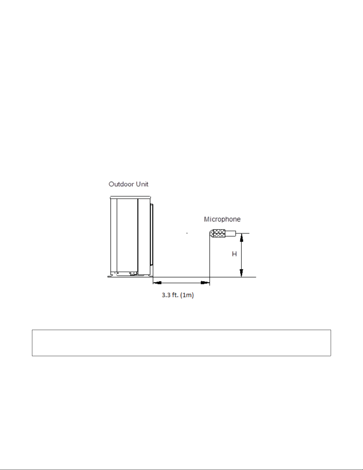
OUTDOOR UNIT SOUND PRESSURE TEST CONDITIONS
41.8
Fig. 10 − Outdoor Unit Sound Pressure Test Conditions
NOTE: H=0.5 x Height of the outdoor unit.
INDOOR CONDITION OUTDOOR CONDITION
DB WB DB WB
Cooling 80.6F (27C) 66.2F (19C) 95F (35C) 75.2F (24C)
Heating 68F (20C) 59F (15C) 44.6F (7C) 42.8F (6C)
19
Page 20

FAN AND MOTOR SPECIFICATIONS
Outdoor
Outdoor
Fan
Motor
18K
(208/230 V)
Material AS AS AS AS AS
Type ZL490*151*12-3KN ZL560*139*12-3KN ZL560*139*12-3KN ZL554*148*12-3KFN ZL554*148*12-3KFN
Diameter inch 490 560 560 554 554
Height inch 151 139 139 148 148
Model ZKFN-50-8-2 ZKFN-120-8-2 ZKFN-120-8-2 ZKFN-85-8-22 ZKFN-85-8-22
Volts V 208/230 208/230 208/230 208/230 208/230
Phase 1 1 1 1 1
Hertz Hz 60 60 60 60 60
FLA 0.74 0.9 1.3 1.0x2 1.0x2
Rated HP HP 0.07 0.16 0.16 0.11 0.11
Output W 50 120 120 85 85
Type DC DC DC DC DC
Insulation
class
Safe class IPX4
Input W 115 156 156 108 108
Range
of current
Rated
current
Capacitor µF No Capacitor
Speed
Rated
RPM
Max. input W 130 173 173 126 126
Amps 0.41±10% 1.34±10% 1.34±10% 0.92±10% 0.92±10%
Amps 0.41 1.34 1.34 0.92 0.92
rev/
min
rev/
min
850~150 1000~150 1000~150 870~300 870~300
800 900 900 800 800
24K
(208/230 V)
30K
(208/230 V)
A
36K
(208/230 V)
ELECTRICAL DATA
UNIT SIZE
18
SYSTEM VOLTAGE OPERATING VOLTAGE COMPRESSOR OUTDOOR FAN
VOLT / PHASE / HZ MAX / MIN* RLA FLA HP W
10 0.74 0.07 50 18 25
24 15 0.9 0.16 120 25 35
30 19 1.3 0.16 120 30 45
208-230/1/60 253 / 187
36 21 1.0x2 0.11 85 35 50
48 21 1.0x2 0.11 85 35 50
MCA
48K
(208/230 V)
MOCP
*Permissible limits of the voltage range at which the unit will operate satisfactorily.
LEGEND
FLA - Full Load Amps
MCA - Minimum Circuit Amps
MOCP - Maximum Over Current Protection
RLA - Rated Load Amps
20
Page 21

WIRING DIAGRAM
CN4
CN2
BLUE
REACTOR
CN5
~
~
CN3
BLUE
NOTE:Use the magnetic ring
(not supplied, optional part)
to hitch the connective cable
of indoor and outdoor units
after installation. one magnetic
ring is used for one cable.
IPM BOARD
V
U
RED
BLUE
V(S)
U(R)
COMPRESSOR
Y/G
W
W(C)
BLACK
CN1
RED(BROWN)
BLUE
CN14
3
3
DC FAN
CN29
L-OUT
21
&20
5<
BROWN
L2(A)
72$
BLUE
S(A)
L1-IN
CN3
BLACK
L1(B)
P-1
BROWN
L2(B)
TO B
Y/G
L2-IN
CN4
BLUE
S(B)
BLACK
S-B
S-A
CN25
CN23
3
3
L1
RED
BLACK
L2
POWER
6833/<
Y/G
Y/G
L1(A)
Y/G
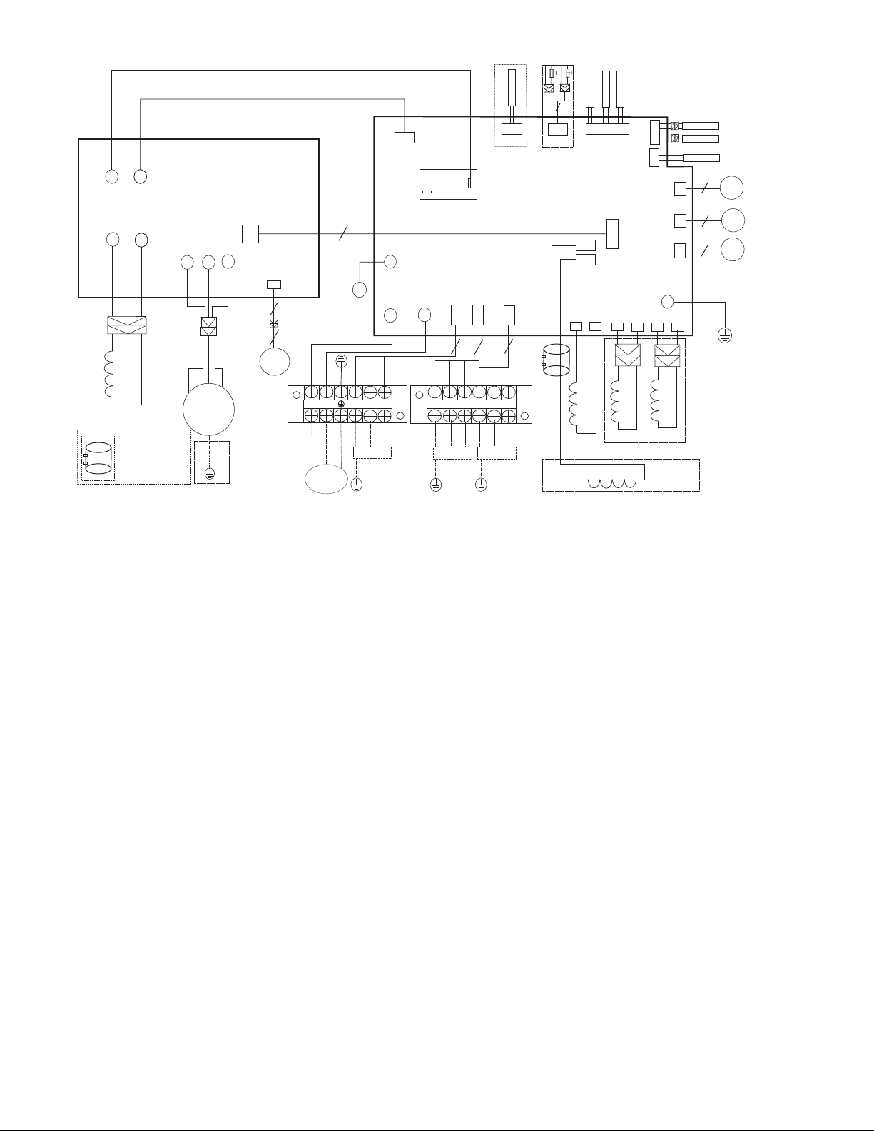
Fig. 10 − Wiring Diagram 18K − 2 Zone
A
RED
YELLOW
4
LOW PRESSURE PROTECT
HIGH PRESSURE PROTECT
CN12
CompTop
CN14
LOW/HIGH
MAIN BOARD
P1
P2
WHITE
WHITE
4-WAY
CN1
CN2
4-WAY
REACT0R2 R05094A
CN15
T2B
B
INDOOR PIPE
OUT TEMP
CN21
HEAT1
CN6
CN5
HEATER1
OPTIONAL
CN17
CN7
VALVE-B
VALVE-A
P-2
HEAT2
CN9
HEATER2
OPTIONAL
CN8
CN19
CN18
287'225$0%,(17
T4
7(03(5$785(6(1625
&21'(16(5
T3
7(03(5$785(6(1625
',6&+$5*(6(1625
6
6
Y/G
ELECTRONIC
EXPANSIVE
VALVE
ELECTRONIC
EXPANSIVE
VALVE
OUTDOOR UNIT MAIN BOARD
CODE PART NAME
CN3~CN4 Input: 230VAC High voltage
CN23,CN25 Output: Pin1 (Connection of the high voltage)---“S"Pin2~Pin3 (230VAC High voltage)---“L1 & L2"
P1~P2 Output: Connection of the REACTOR
CN1~CN2 Output: 230VAC High voltage ----4 Way Valve
CN5~CN6 Output: 230VAC High voltage----Compressor Crankcase Heater
CN8~CN9 Output: 230VAC High voltage----Chassis Crankcase Heater
P-1~P-2 Connection to the earth
CN18, CN19 Output: Pin1-Pin4: Pulse waveform (0-12VDC), Pin5, Pin6 (12VDC)--EEV
CN7 Input:Pin1 (0-5VDC), Pin2 (5VDC)--Discharge Sensor
CN17 Input: Pin3, Pin4 (5VDC), Pin2 (0VDC), Pin1, Pin5 (0-5VDC)-Cond. and Ambient Temperature
CN15 Input: Pin1, Pin3, Pin5 (5VDC) Pin2, Pin4, Pin6 (0-5VDC)--IDU Pipe Temp
CN14 Input: Pin2, Pin4 (0VDC), Pin1, Pin3 (0-5VDC)---H/L Pressure Switches
CN12 Input: Pin1 (0-5VDC), Pin2 (5VDC)--Compressor Temp
CN29~L-OUT Output: 230VAC High voltage--to IPM Board
CN 21 Connect to IPM BOARD
OUTDOOR UNIT IPM BOARD
CODE PART NAME
CN4~CN5 Input: 230VAC High voltage---from the Main Board
CN2~CN3 Output: Connection of the REACTOR
U~V~W Connection to compressor voltage among phases 0~200VAC
CN14 Connection to DC FAN
CN1 Connection to MAIN BOARD
21
Page 22
WIRING DIAGRAMS (CONT)
RED(BROWN)
BLUE
CN4
CN2
BLUE
REACTOR
CN5
~
~
CN3
BLUE
NOTE:Use the magnetic ring
(not supplied, optional part)
to hitch the connective cable
of indoor and outdoor units
after installation. one magnetic
ring is used for one cable.
IPM BOARD
CN1
V
U
W
BLACK
RED
BLUE
V(S)
U(R)
W(C)
COMPRESSOR
Y/G
CN14
3
3
DC FAN
RED
L1 L2
6833/<
BLACK
POWER
C
A
B
INDOOR PIPE
CN2
4-WAY
CN15
T2B
CN21
CN6
HEAT1
OUT TEMP
CN5
HEATER1
OPTIONAL
CN17
CN7
VALVE-C
VALVE-B
VALVE-A
P-2
HEAT2
CN9
HEATER2
OPTIONAL
CN8
CN22
CN19
CN18
287'225$0%,(17
T4
7(03(5$785(6(1625
&21'(16(5
T3
7(03(5$785(6(1625
',6&+$5*(6(1625
6
6
6
Y/G
ELECTRONIC
EXPANSIVE
VALVE
ELECTRONIC
EXPANSIVE
VALVE
ELECTRONIC
EXPANSIVE
VALVE
RED
YELLOW
4
LOW PRESSURE PROTECT
HIGH PRESSURE PROTECT
L-OUT
5<
CN12
CompTop
CN29
21
&20
BROWN
L2(A)
72$
Y/G
BLUE
S(A)
L1-IN
CN3
P-1
BLACK
L2-IN
CN4
BROWN
L1(B)
S-A
BLUE
L2(B)
72%
Y/G
S-B
CN25
CN23
33
BLACK
BROWN
S(B)
L2(C)
L1(C)
72&
Y/G
BLUE
S-C
3
BLACK
S(C)
Y/G
Y/G
L1(A)
CN14
LOW/HIGH
MAIN BOARD
P1
P2
WHITE
WHITE
CN20
4-WAY
CN1
REACT0R2 R05094A
Fig. 11 − Wiring Diagrams 24K − 3 Zone Max
OUTDOOR UNIT MAIN BOARD
CODE PART NAME
CN3~CN4 Input: 230VAC High voltage
CN20,CN23,CN25 Output: Pin1 (Connection of the high voltage)---“S" Signal Pin2~Pin3 (230VAC High voltage)---IDU Power
P1~P2 Output: Connection of the REACTOR
CN1~CN2 Output: 230VAC High voltage---4 way Valve
CN5~CN6 Output: 230VAC High voltage---Compressor Crankcase Heater
CN8~CN9 Output: 230VAC High voltage---Chassis Crankcase Heater
P-1~P-2 Connection to the earth
CN18,CN19,CN22 Output: Pin1-Pin4: Pulse waveform (0-12VDC), Pin5, Pin6 (12VDC)---EEV
CN7 Input: Pin1 (0-5VDC), Pin2 (5VDC) --- Discharge Temp
CN17 Input: Pin3, Pin4 (5VDC), Pin2 (0VDC), Pin1, Pin5 (0-5VDC)-Conditioner and Ambient Temperature
CN15 Input: Pin1, Pin3, Pin5 (5VDC) Pin2, Pin4, Pin6 (0-5VDC) --- IDU Pipe Temp
CN14 Input: Pin2, Pin4 (0VDC), Pin1, Pin3 (0-5VDC) --- H/L Pressure Switch
CN12 Input: Pin1 (0-5VDC), Pin2 (5VDC) --- Compressor Temp
CN29~L-OUT Output: 230VAC High voltage to IPM Board
Cn21 Connect to the IPM BOARD
OUTDOOR UNIT IPM BOARD
CODE PART NAME
CN4~CN5 Input: 230VAC High voltage
CN2~CN3 Output: Connection of the REACTOR
U~V~W Connect to compressor voltage among phases 0~200VAC
CN14 Connect to the DC FAN
CN1 Connect to the MAIN BOARD
22
Page 23

WIRING DIAGRAMS (CONT)
Applicable to the units
adopting DC motor only
3
3
CN19
CN55
CN53
CN52
CN54
DRIVER BOARD
BLUE
BLUE
Y/G
COMP
BLACK
W
RED
V
BLUE
U
U
V
W
CN51
FM1
7
Y/G
OPTIONAL
BLACK
RED
4-WAY1
BLUE
HEAT_Y
HEAT_D
SV
BLUE
7
BLUE
RED
RED
CN43
CN3
CN4
CN10
CN5
CN6
CN1
CN2
BLUE
BLACK
BLACK
L-PRO
CN41
CN42
CN22
CN40
CN44
CN7
CN30
3
H-PRO
T4
CN8
CN9
MAIN BOARD
CN29
3
3
T3
CN28
CN33
TP
A
CN20
CN21
B
C
CN17
D
CN18
E
CN19
T2B-A B C D E
CN13
P-1
CN27
3
5(6)
5(6)
5(6)
5(6)
5(6)
M
M
EEV
M
M
M
TEMP A B C D E
Y/G
INDOOR PIPE OUT
YELLOW
L
YELLOW
RED
L1 L2
POWER
6833/<
BLACK
YELLOW
L1(A)
BLUE
BROWN
L2(A)
TO A
S(A)
BLACK
L1(B)
Y/G
Fig. 12 − Wiring Diagrams 30K − 4 Zone Max
OUTDOOR UNIT MAIN BOARD
CODE PART NAME
CN1~CN2 Input: 230VAC High voltage
CN5~CN6 Output: 230VAC High voltage
P-1 Connection to the earth
CN10~CN44 Output: 230VAC High voltage Chassis Crankcase Heater
CN4~CN40 Output: 230VAC High voltage Compressor Crankcase Heater
CN3~CN22 Output:230VAC High voltage
CN17~CN21 Output: Pin1-Pin4: Pulse waveform (0-12VDC), Pin5, Pin6 (12VDC)
CN7 Output: Pin1 (12VDC), Pin2 (5VDC), Pin3 (EARTH)
CN27~CN30 Output: Pin 2~Pin 3 (230VAC High voltage) - IDU Power & "S"
CN13 Pin1, Pin3, Pin5, Pin7, Pin9 (5VDC ); Pin2, Pin4, Pin6, Pin8, Pin10 (0-5VDC)
CN33 Input: Pin1 (0-5VDC), Pin2 (5VDC) - Discharge Temp
CN8 Input: Pin3, Pin4 (5VDC), Pin2 (0VDC), Pin1, Pin5 (0-5VDC) T3 & T4
CN9 Input: Pin2, Pin4 (0VDC), Pin1, Pin3 (0-5VDC) H/L Pressure Switches
BLUE
BROWN
L2(B)
TO B
S(B)
BLACK
L1(C)
Y/G
BROWN
L2(C)
TO C
BLUE
S(C)
BLACK
L1(D)
Y/G
BLUE
BROWN
L2(D)
TO D
BLACK
S(D)
Y/G
OUTDOOR UNIT PFC & IPM BOARD
CODE PART NAME
CN53~CN54 Input: 230VAC High voltage
CN55 Output: Pin1 (12VDC),Pin2 (5VDC),Pin3 (EARTH)
CN19 Pin1~Pin3: Connect to FAN voltage among phases 0~200VAC
U~V~W Connect to compressor voltage among phases 0~200VAC
CN51~CN52 CN51~EARTH ,CN52~EARTH Output: 224-380VDC High voltage
CODE PART NAME CODE PART NAME
COMP COMPRESSOR L PFC INDUCTOR
CAP1 FAN MOTOR CAPACITOR L-PRO LOW PRESSURE SWITCH
HEAT CRANKCASE HEATING TP EXHAUST TEMPERATURE SENSOR
FM1 OUTDOOR DC FAN SV 4-WAY VALVE
FAN1 OUTDOOR AC FAN T3 CONDENSER TEMPERATURE SENSOR
EEV ELECTRONIC EXPANSION VALVE T4 OUTDOOR AMBIENT TEMPERATURE SENSOR
H-PRO HIGH PRESSURE SWITCH TH HEATSINK TEMPERATURE SENSOR
23
Page 24
WIRING DIAGRAMS (CONT)
b
Notes:
This symbol indicates the element
is optional,the actual shape shall
e prevail.
L
BLACK
YELLOW
CN2
CN6
CH1
Ferrite bead
V
U
W
COMP
Y/G
Ferrite bead
CH2
Y/G
DCFAN2
DCFAN1
Y/G
CH2
D
Ferrite bead
CH2
Ferrite bead
BLUE
RED
BLACK
DC MOTOR
DRIVER BOARD
3
3
FAN 1
PIPE TEMP.SENSOR
AMBIENT SENSOR
INDOOR
PIPE OUT
TEMP
4
5
U
3
CN1
FAN 2
VA LVE E
L-PRO
H-PRO
12
3
2
PAIQI
RED
YELLOW
CN1
CN3
IPM & PFC BOARD
FAN1
Ferrite bead
CH2
ELECTRONIC EXPANSIVE VALVE A
ELECTRONIC EXPANSIVE VALVE B
ELECTRONIC EXPANSIVE VALVE C
ELECTRONIC EXPANSIVE VALVE D
ELECTRONIC EXPANSIVE
BLACK
~
~
RED
~
W
V
CN9
CON1
TH
A
B
C
D
E
RED
RED
RED
RED
RED
RED
YELLOW
P6
CN4
CT1
CN2
MAIN BOARD
10
CN6
CN12
CN8
T3
CN9
T4
T2B
A
B
C
D
CN11
E
CN15
A
CN23
B
CN26
C
CN30
D
CN33
E
CN10
XT1
XT2
L2
L1
XT3
SV
N
L
S(E)
L2(E)
L1(E)
S(D)
L2(D)
L1(D)
S(C)
L2(C)
L1(C)
S(B)
L2(B)
L1(B)
S(A)
L2(A)
L1(A)
Ferrite bead
OPTIONAL
4-WAY
MAIN
POWER SUPPLY
OPTIONAL
HEAT_D
HEAT_Y
TO D
TO C
TO B
TO A
CN1
E
CN13
D
C
CN21
B
A
CN20
CN25
CN18
CN28
CN31
CN36
CN32
CN27
CN34
Y/G
BLACK
WIHTE
/RED
P9
BLACK
3
BLUE
BROWN
BLACK
3
BLUE
BROWN
BLACK
3
BLUE
BROWN
BLACK
3
BLUE
BROWN
BLACK
3
BLUE
BROWN
BLACK
RED
ORANGE
ORANGE
BLUE
BLUE
P5
CN3
CN16
CN29
CN37
CN19
CN24
CN17
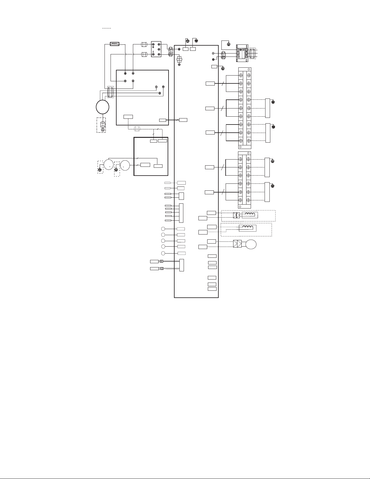
Fig. 13 − Wiring Diagrams 36K − 4 Zone Max
OUTDOOR UNIT MAIN BOARD
CODE PART NA M E
CN1~ CN3 Input: 230VAC High voltage
CN13, CN16, CN21, CN29, CN37 Output: Pin1(Connection of the high voltage) “S" Pin2~ Pin3 (230VAC High voltage)“L1&L2"
P5, P6, P9 Connection to the earth
CN22 Output:-24VDC-24VDC
CN17~ CN18 Output: 230VAC High voltage to 4 way valve
CN19~ CN20 Output: 230VAC High voltage Compressor Crankcase Heater
CN24~ CN25 Output: 230VAC High voltage Chassis Crankcase Heater
CN11 Input: Pin1, Pin3, Pin5, Pin7, Pin9 (5VDC) Pin2, Pin4, Pin6, Pin8, Pin10 (0-5VDC) indoor pipe out sensor
CN12 Input: Pin1 (0-5VDC), Pin2 (5VDC) Heatsink Temperature Sensor
CN8 Input: Pin1 (0-5VDC), Pin2 (5VDC) Compressor top sensor(PAIQI)
CN9 Input: Pin3, Pin4 (5VDC), Pin2 (0VDC), Pin1, Pin5 (0-5VDC) Pipe sensor and ambient sensor
CN15, CN23, CN26 CN30, CN33 Output: Pin1-Pin4: Pulse waveform (0-12VDC), Pin5, Pin6 (12VDC) to EEV
CN6
Communication: Pin1-Pin6: Pulse waveform (0-5VDC), Pin7, Pin9 (0VDC) Pin8 (0-5VDC), Pin10
(5VDC)--to IPM & PFC board
CN2~ CN4 Output: 230VAC High voltage to IPM & PFC Board
CN10 Input: Pin2, Pin4 (0VDC), Pin1, Pin3 (0-5VDC)--H/L Pressure switch
24
Page 25

OUTDOOR UNIT PFC and IPM BOARD
CODE PART NAME
CN1~CN6 Output: 224-380VDC High voltage
CN2~CN6 Output: 224-380VDC High voltage
CN3~CN6 Output: 224-380VDC High voltage
U~V~W Connect to compressor voltage among phases 0~200VAC
CN9
FAN1
CODE PART NAME
CON1 Output: Pin1~Pin2:High voltage (224-380VDC)
CN1 Input:Pin4: Pulse waveform (0-15VDC), Pin3 (0-6.5VDC) Pin2 (0VDC), Pin1 (15VDC)
FAN1 Pin1-Pin3: Connect to FAN voltage among phases 0~200VAC
FAN2 Pin1-Pin3: Connect to FAN voltage among phases 0~200VAC
CODE PART NAME
COMP COMPRESSOR
CAP1,CAP2 FAN MOTOR CAPACITOR
CT1 AC CURRENT DETECTOR
D DIODE MODULE
EEV ELECTRONIC EXPANSION VALVE
FM1, FM2 OUTDOOR DC FAN
FAN1, FAN2 OUTDOOR AC FAN
HEAT CRANKCASE HEATING
H-PRO HIGH PRESSURE SWITCH
L PFC INDUCTOR
L-PRO LOW PRESSURE SWITCH
KM AC CONTACTOR
SV 4-WAY VALVE
TP EXHAUST TEMPERATURE SENSOR
T3 CONDENSER TEMPERATURE SENSOR
T4 OUTDOOR AMBIENT TEMPERATURE SENSOR
TH HEATSINK TEMPERATURE SENSOR
PAIQI COMPRESSOR TOP SENSOR(GAS PIPE)
CH1, CH2, CH3 FERRITE BEAD
Communication: Pin1-Pin6: Pulse waveform (0-5VDC), Pin7, Pin9 (0VDC), Pin8 (0-5VDC), Pin10 (5VDC) to the main
board
Output: Pin1~Pin2: High voltage (224-380VDC), Pin4 (0-15VDC) Pin5 (0-5.6VDC), Pin6: Pulse waveform (0-15VDC)
to drive board
OUTDOOR UNIT DC MOTOR DRIVER BOARD
25
Page 26

WIRING DIAGRAMS (CONT)
b
Notes:
This symbol indicates the element
is optional,the actual shape shall
e prevail.
L
BLACK
YELLOW
CN2
CH1
Ferrite bead
V
U
W
COMP
Y/G
Ferrite bead
CH2
Y/G
DCFAN2
Y/G
CH2
Ferrite bead
RED
CH2
Ferrite bead
YELLOW
CN1
CN3
CN6
BLUE
RED
BLACK
IPM & PFC BOARD
FAN1
Ferrite bead
CH2
CN1
DC MOTOR
DRIVER BOARD
3
3
FAN 1
DCFAN1
PIPE TEMP.SENSOR
AMBIENT SENSOR
INDOOR
PIPE OUT
TEMP
ELECTRONIC EXPANSIVE VALVE A
ELECTRONIC EXPANSIVE VALVE B
ELECTRONIC EXPANSIVE VALVE C
ELECTRONIC EXPANSIVE VALVE D
ELECTRONIC EXPANSIVE
VA LV E E
L-PRO
H-PRO
D
4
12
3
5
U
V
2
3
CON1
FAN2
PAIQI
BLACK
~
~
RED
~
W
CN9
TH
A
B
C
D
E
RED
RED
RED
RED
RED
RED
YELLOW
P5
P6
CN4
CT1
CN2
MAIN BOARD
10
CN6
CN12
CN8
T3
CN9
T4
T2B
A
B
C
D
CN11
E
CN15
A
CN23
B
CN26
C
CN30
D
CN33
E
CN10
CN19
CN24
CN17
CN3
CN1
E
CN13
D
CN16
C
CN21
B
CN29
A
CN37
CN20
CN25
CN18
CN28
CN31
CN36
CN32
CN27
CN34
P9
Y/G
BLACK
WIHTE
/RED
BLACK
3
BLUE
BROWN
BLACK
3
BLUE
BROWN
BLACK
3
BLUE
BROWN
BLACK
3
BLUE
BROWN
BLACK
3
BLUE
BROWN
BLACK
RED
ORANGE
ORANGE
BLUE
BLUE
XT2
XT1
Ferrite bead
N
L2
L
L1
XT3
S(E)
L2(E)
L1(E)
S(D)
L2(D)
L1(D)
S(C)
L2(C)
L1(C)
S(B)
L2(B)
L1(B)
S(A)
L2(A)
L1(A)
4-WAY
SV
MAIN
POWER SUPPLY
OPTIONAL
HEAT_D
HEAT_Y
OPTIONAL
TO E
TO D
TO C
TO B
TO A
Fig. 15 − Wiring Diagrams 48K − 5 Zone Max
OUTDOOR UNIT MAIN BOARD
CODE PART NAME
CN1~CN3 Input: 230VAC High voltage
CN13,CN16,CN21,CN29,CN37 Output: Pin1 (Connection of the high voltage) “S" Pin2~Pin3 (230VAC High voltage) “L1&L2"
P5,P6,P9 Connection to the earth
CN22 Output:-24VDC-24VDC
CN17~CN18 Output: 230VAC High voltage to 4 way valve
CN19~CN20 Output: 230VAC High voltage Compressor Crankcase Heater
CN24~CN25 Output: 230VAC High voltage Chassis Crankcase Heater
CN11 Input: Pin1, Pin3, Pin5, Pin7, Pin9 (5VDC) Pin2, Pin4, Pin6, Pin8, Pin10 (0-5VDC) indoor pipe out sensor
CN12 Input: Pin1 (0-5VDC), Pin2 (5VDC) Heatsink Temperature Sensor
CN8 Input: Pin1 (0-5VDC), Pin2 (5VDC) Compressor top sensor (PAIQI)
CN9 Input: Pin3, Pin4 (5VDC), Pin2 (0VDC), Pin1, Pin5 (0-5VDC) Pipe sensor and ambient sensor
CN15,CN23,CN26 CN30,CN33 Output: Pin1-Pin4: Pulse waveform (0-12VDC), Pin5, Pin6 (12VDC) to EEV
CN6 Communication: Pin1-Pin6: Pulse waveform(0-5VDC), Pin7, Pin9 (0VDC) Pin8 (0-5VDC), Pin10 (5VDC)--to IPM&PFC
board
CN2~CN4 Output: 230VAC High voltage to IPM & PFC Board
CN10 Input: Pin2, Pin4 (0VDC), Pin1, Pin3 (0-5VDC)--H/L Pressure switch
26
Page 27

OUTDOOR UNIT PFC and IPM BOARD
CODE PART NAME
CN1~CN6 Output: 224-380VDC High voltage
CN2~CN6 Output: 224-380VDC High voltage
CN3~CN6 Output: 224-380VDC High voltage
U~V~W Connect to compressor voltage among phases 0~200VAC
CN9 Communication: Pin1-Pin6: Pulse waveform (0-5VDC), Pin7, Pin9 (0VDC), Pin8 (0-5VDC), Pin10 (5VDC) to the main board
FAN1 Output: Pin1~Pin2: High voltage (224-380VDC) ,Pin4 (0-15VDC) Pin5 (0-5.6VDC), Pin6: Pulse waveform (0-15VDC) to drive board
OUTDOOR UNIT DC MOTOR DRIVER BOARD
CODE PART NAME
CON1 Output: Pin1~Pin2: High voltage (224-380VDC)
CN1 Input: Pin4: Pulse waveform (0-15VDC), Pin3 (0-6.5VDC) Pin2 (0VDC),Pin1 (15VDC)
FAN1 Pin1-Pin3:Connect to FAN voltage among phases 0~200VAC
FAN2 Pin1-Pin3:Connect to FAN voltage among phases 0~200VAC
CODE PART NAME
COMP COMPRESSOR
CAP1,CAP2 FAN MOTOR CAPACITOR
CT1 AC CURRENT DETECTOR
D DIODE MODULE
EEV ELECTRONIC EXPANSION VALVE
FM1, FM2 OUTDOOR DC FAN
FAN1,FAN2 OUTDOOR AC FAN
HEAT CRANKCASE HEATING
H-PRO HIGH PRESSURE SWITCH
L PFC INDUCTOR
L-PRO LOW PRESSURE SWITCH
KM AC CONTACTOR
SV 4-WAY VALVE
TP EXHAUST TEMPERATURE SENSOR
T3 CONDENSER TEMPERATURE SENSOR
T4 OUTDOOR AMBIENT TEMPERATURE SENSOR
TH HEATSINK TEMPERATURE SENSOR
PAIQI COMPRESSOR TOP SENSOR (GAS PIPE)
CH 1, CH 2, CH 3 FERRITE BEAD
27
Page 28

Size Range:1 1/2, 2, 2 1/2, 3 and 4 Ton Nominal Cooling and Heating Capacity
PART 1 – GENERAL
1.01 System Description
A. Outdoor air−cooled split system compressor sections suitable
for on−the−ground, rooftop, wall hung or balcony mounting.
Units consist of a variable speed rotary compressor, an
air−cooled coil, propeller−type draw−through outdoor fan,
reversing valve, accumulator, electronic expansion valves,
multiple service valves, and controls that allows multiple
indoor units to be connected to the outdoor unit. Units
discharge horizontally as shown on the contract drawings.
Units function as the outdoor component of an air−to−air heat
pump system.
B. Units are designed to be used in a refrigeration circuit matched
to two, three, four, or five multi style heat pump fan coil units.
1.02 Agency Listings
A. Unit construction complies with ANSI/ASHRAE 15, latest
revision, and with NEC.
B. Units are evaluated in accordance with UL standard 1995.
C. Units are listed in CEC directory.
D. Unit cabinet is capable of withstanding 500-hour salt spray test
per Federal Test Standard no. 141 (method 6061).
E. Air-cooled condenser coils are leak tested at 550 psig.
1.03 Delivery, Storage, And Handling
Units are shipped in one piece and are stored and handled per the
manufacturer’s recommendations.
1.04 Warranty (For Inclusion By Specifying Engineer)
PART 2 – PRODUCTS
2.01 Equipment
A. General:
Factory assembled, single piece, air-cooled outdoor unit. Contained
within the enclosure are the factory wiring, piping, controls, and
compressor.
B. Unit Cabinet:
1. The unit cabinet is constructed of galvanized steel,
bonderized and coated with baked-enamel finish on inside
and outside.
2. The unit access panel is removable with the minimal screws
and provides full access to the compressor, fan, and control
components.
3. The outdoor compartment is isolated and has an acoustic
lining to assure quiet operation.
GUIDE SPECIFICATIONS
HORIZONTAL DISCHARGE OUTDOOR UNITS
Carrier Model Number: 38MGR
C. Fans:
1. The outdoor fans are direct-drive propeller type, and
discharge air horizontally. The fan draws air through the
outdoor coil.
2. Outdoor fan motors are multi−speed, totally-enclosed,
single phase motors with permanently lubricated ball
bearings. The motor is protected by internal thermal
overload protection.
3. The shaft has an inherent corrosion resistance.
4. Outdoor fan openings are equipped with metal/mesh PVC
coated protection grille over fan.
D. Compressor
1. The compressor is fully hermetic variable speed rotary type.
2. The compressor is inverter driven.
3. The compressor is equipped with an oil system, operating
oil charge, and motor.
4. The motor is suitable for operation in a refrigerant and oil
atmosphere.
5. The compressor assembly is installed on rubber vibration
isolators.
6. The inverter and compressor are protected against over
temperature and over current.
E. Outdoor Coil:
The coil is constructed of aluminum blue hydrophilic pre−coated
fins mechanically bonded to seamless copper tubes, which are
cleaned, dehydrated and sealed.
F. Refrigerant Components:
Refrigerant circuit components include multiple brass external
liquid line service valves with service gauge connection port,
multiple suction line service valves with a service gage connection
port, accumulator, reversing valve, electronic expansion valves.
G. Safeties:
Operating safeties are factory selected, assembled, and tested. The
minimum functions include the following:
1. Compressor discharge over temperature protection.
2. System low voltage protection.
3. Compressor overload protection.
4. Compressor over current protection.
5. IPM module protection.
H. Electrical Requirements:
1. Units shall operate on single-phase, 60 Hz power at
208/230v.
2. The unit electrical power is a single point connection.
3. All power and control wiring must be installed per NEC
and all local electrical codes.
4. Units have multiple terminal blocks to connect to multiple
indoor units.
Copyright 2016 Carrier Corp. D 7310 W. Morris St. D Indianapolis, IN 46231 . Edition Date: 06/16
Manufacturer reserves the right to change, at any time, specifications and designs without notice and without obligations.
28
Catalog No: 38MGR-01PD
Replaces: NEW
 Loading...