


Number One
Ai'rConditbninq
Maker
Divisiun uf
Carrier Corporation
Carrier Parkway • Syracuse NY 13221
Weathermaster III Heat Pump
(Outdoor Coil Section; Indoor Compressor Section)
INDEX
Page
SAFETY CONSIDERATIONS...............................1
INSTALLATION
...................................................
1-8
Step 1 — Check Equipment and
Jobsite...............................................I
• UNPACKAGE UNITS
• INSPECT EQUIPMENT
• COMPLETE OR CONSIDER SYSTEM
REQUIREMENTS
Step 2 — Mount Outdoor Coil Unit
....................
3
• ON THE GROUND: MOUNT OUTDOOR
COIL ON A SOLID, LEVEL CON
CRETE PAD
• ON THE ROOF: MOUNT OUTDOOR
COIL ON A LEVEL PLATFORM
OR FRAME
Step3 — Mount Indoor Compressor
Section
Step 4 — Make Piping Connections
.............................................
..................
5
5
• REPLACE THE ACCURATER™ RE
FRIGERANT CONTROL PISTON IN
THE INDOOR COIL AS REQUIRED
• CONNECT REFRIGERANT LINES
Step 5 — Make Electrical Connections .. 7
• INSTALL A BRANCH CIRCUIT
DISCONNECT PER NEC
• BRING LINE POWER LEADS INTO
COMPRESSOR SECTION
• CONNECT GROUND LEADS AND i
POWER WIRING
• CONNECT POWER LEADS FROM
INDOOR COMPRESSOR SECTION
TO OUTDOOR COIL
• SEE INDOOR FAN COIL AND
ELECTRIC HEATER INSTALLATION,
START-UP AND SERVICE
INSTRUCTIONS
• CONNECT CONTROL POWER
WIRING
START-UP
...........................................................
8, 9
SERVICE............................................................10-17
MAINTENANCE ................................................. 17
SAFETY CONSIDERATIONS
Installation and servicing of air conditioning
equipment can be hazardous due to system pressure
and electrical components. Only trained and quali
fied service personnel should install, repair or
service air conditioning equipment.
Untrained personnel can perform basic mainten
ance functions of cleaning coils and filters and
replacing filters. All other operations should be
performed by trained service personnel. When
working on air conditioning equipment, observe
precautions in the literature, tags and labels
attached to the unit and other safety precautions
that may apply.
Follow all safety codes. Wear safety glasses and
work gloves. Use quenching cloth for brazing and
unbrazing operations. Have fire extinguisher avail
able for all brazing operations.
WARiNIMG: Before peri'orBEiisg: service or
laaintenaac« operadotis os. mtHL tiina oif rtsian
pow«f switch to ctait, T om OB' accessosy heater
power iwlich, if ap-ptlrcaiBe, Ekofticai shock
coold muse personal
INSTALLATION
Step 1 — Check Equipment and Jobsite
UNPACKAGE UNITS — Move to final location.
Slide from cartons taking special care not to damage
service valves. Compatible Fittings or grilles.
INSPECT EQUIPMENT — File claim with ship
ping company if shipment is damaged or
incomplete.
COMPLETE OR CONSIDER SYSTEM RE
QUIREMENTS before installing the 38HQ:
Consult local building codes and National
Electrical Code (NEC) for special installation
requirements.
When installing, allow sufficient space for airflow
clearance (outdoor unit), wiring, refrigerant piping
and servicing unit. Position outdoor unit so water or
ice from roof cannot drop directly on top of unit.
Maximum allowable vertical distance between
indoor and outdoor sections is 50 feet. It is strongly
recommended that 38HQ units be used with Carrier
approved indoor sections. See Table 3.
© Carrier Corporation 1981
Form 38HQ-10SI
4-0" OVERHEAD SPACE REQUIRED
FOR SERVICE AND AIRFLOW
OUTDOOR
SECTION
i DIAM HOLE
LIQUID LINE
CONN
ik-If
MTG SLOTS
(USE ANY 2 TO
BOLT UNIT DOWN)
FOR CONTROL
WIRING
DRAINAGE HOLES
- If DIAM
HOLE FOR
POWER WIRING
SPACE REQUIRED FOR SERVICE E# AIRFLOW
Certified dimension drawings available on request
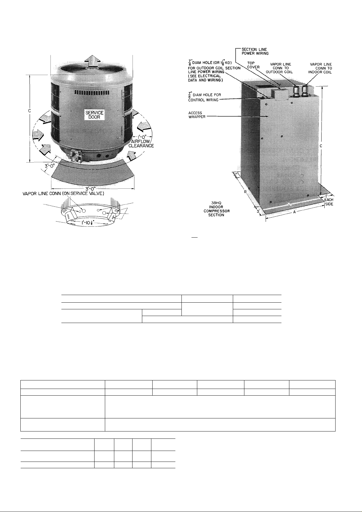
Fig. 1 —DimensionsandConnections(Tablel)
38HQ
COIL
,M HOLE (OR l|- KO)
FOR COMPRESSOR
mm SPACE REQUIRED
FOR SERVICE
Certified dimension drawings available on request
>Fig. 2 — DimensionsandConnections(Table2)
Table 1 — Installation Data (Outdoor Coil, Fig. 1)
UNIT 1 38HQ940 38HQ960
OPER WT (lb)
DIMENSIONS (ft-in.)
REFRIGERANT CONNECTION (in.)
Vapor* (ODF)
Liquid* (ODF)
‘Recommended field-supplied refrigerant line sizes shown under Table 2
Table 2 — Installation Data (Indoor Compressor Section, Fig. 2)
UNIT 38HQ120
OPERATING WEIGHT (lb)
DIMENSIONS (ft-in )
Length A
Width B
Height C
CONNECTIONS (in. ODF)
Vapor Lines (2)*
‘Recommended refrigerant line sizes
INDOOR COMPR
SECTION 38HQ
OUTDOOR
COIL 38HQ
VAPOR (in OD)
LIQUID (In OD)
120 127
940 940
! 3/4“
3/4
106 1 1 1
134 140
940
3/4 7/8 1-1/8
3/8
960
Diam A
Height C
38HQ127
146t
960t
i
125
■j 2-5-1/4 2-5-1/4
j 2-8
Compatible Fitting (Vapor) & Flare (Liquid)
3-8
. — .. —
3/8
38HQ134
38HQ140
117 141
1-2-3/32
1-4-3/16
1-11-1/8 (Add 2-1/2 in for Refrigerant Fittings)
Compatible Fittings (2)
3/4
->^tThe 38HQ146/38HQ960 system may use 7/8-in accessory^'
tubing package with slight capacity loss, see page 3 For 1-1/8 in (
system vapor line on 38HQ146, 3/4- x 1-1/8 in connection
adapter is available as accessory See Table 4
38HQ146
142
© 783
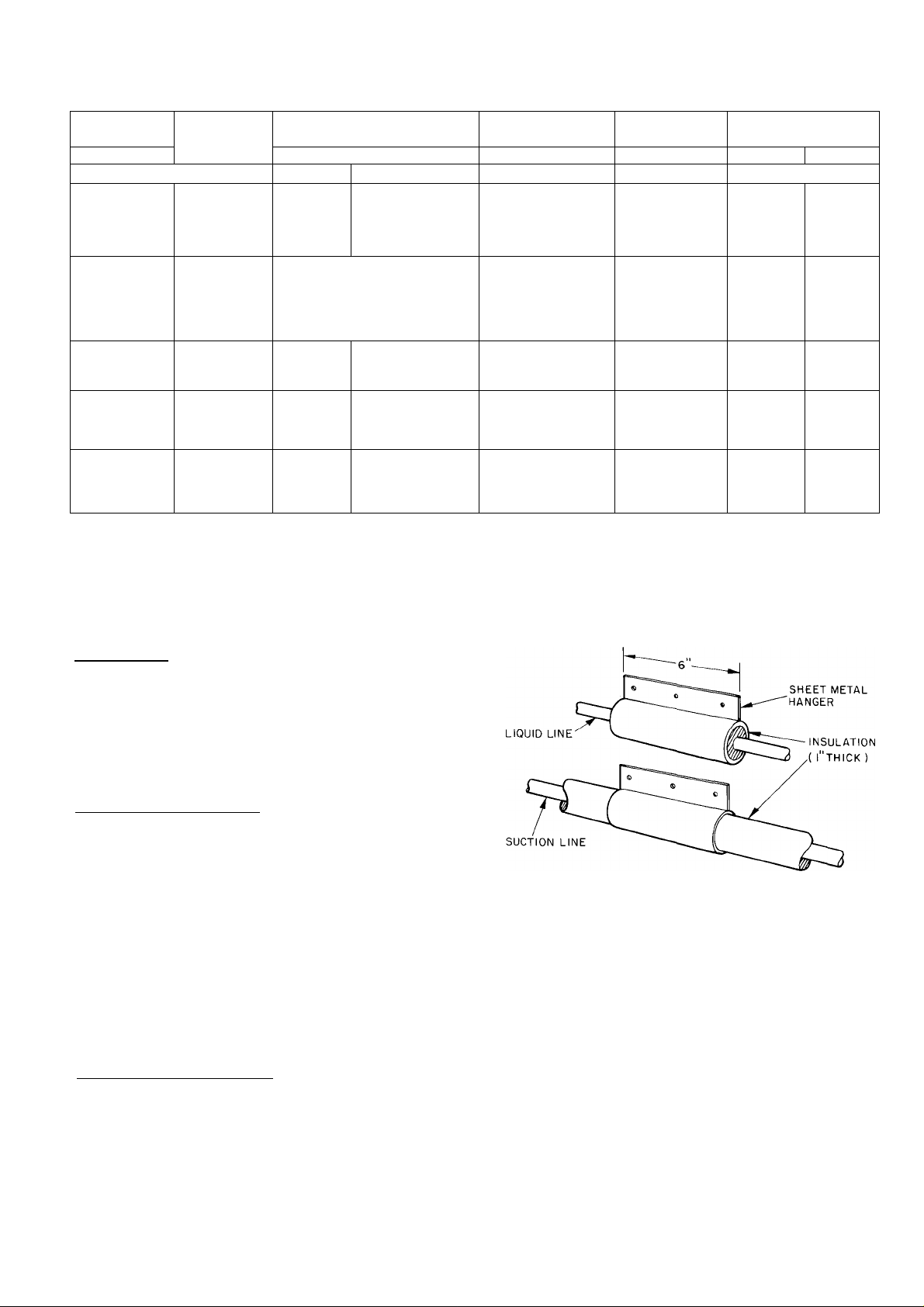
Table 3 ^ Carrier-Approved 38HQ Systems
INDOOR
COMPR
SECTION
120
127
134
140
146
^Change AccuRater Piston to No 46 in Outdoor Coil 38HQ940
when used in combination with Indoor Compressor Section
38HQ120
fWhen the system consists of 38HQ120 Compressor Section/
38HQ940 Outdoor Coil/ and 40AQ036 Indoor Fan Coil, the
factory-installed No 59 AccuRater piston must be removed from
the Outdoor Coil and installed in the Indoor Section As noted
above, a No 46 AccuRater piston is installed in the Outdoor Coil
38HQ
OUTDOOR
COIL
940*
940
940
960
960
INDOOR FAN COIL
L
f0AQ030
L
f0AQ036t
28HQ,VQ030t**
40FS160
— j 28HQ,VQ030**
— 28HQ,VQ036t*‘
40FS160 1 28HQ,VQ036
40FS160
40FS160
40FS200
40FS200
40FS220
28HQ,VQ036**
28HQ,VQ036
40AQ030t
40AQ036Ì
40DQ030
40AQ036
28HQ,VQ036**
28HQ,VQ036
28HQ,VQ042**
28HQ,VQ042
28HQ,VQ042
40QB042
28HQ,VQ048t**
28HQ,VQ048t
28HQ,VQ048
40QB048
INDOOR
ACCURATER™
PISTON PISTON
NO. NO.
59
63 59
70
76 63
82 63
for all 38HQ120 combinations Discard the AccuRater piston
which was factory installed in the Indoor Fan Coil
tindoor units that require replacement of AccuRater refrigerant
control piston for optimum performance when used with speci
fied 38HQ sections Required piston is shown in table and is
supplied with 38HQ compressor section for field installation
**Used in systems with non-specified indoor air moving unit
OUTDOOR
ACCURATER i
46
59
MAX HEIGHT (ft)
INDOOR UNITS
Above Below
Outdoor Coil
50 50
Outdoor Coil — Make provisions for condensate
drainage and defrost water disposal whether unit is
installed on ground, roof or off-the-wall platform.
(Ensure unit basepan drainage holes are not
blocked.) See Mount Outdoor Coil for details. Roof
installation method for 38HQ depends on building
construction and special requirements of local
codes. Make sure roof can support unit weight.
Indoor Compressor Section — Locate unit in base
ment, garage or utility room. Indoor locations
within the living space are not recommended. Base
ment installations also require careful planning to
avoid areas directly under bedrooms, living
rooms, etc.
Insert felt isolation pad (factory supplied) be
tween unit and a rigid mounting base to absorb
vibration. Isolate interconnecting tubing from
framing and ductwork or where tubing runs thru
stud spaces, enclosed ceilings or pipe chases. Use
isolation type hanger. Fig. 3, since rigid fastening
transmits pulsation to structure creating objection
able sound.
System Refrigerant Control on 38HQ units and
matching Carrier indoor fan coil units is a factory-
installed Accu-Rater™ device (bypass type). Bypasstype AccuRater components are shown in Fig. 26.
The AccuRater piston has a refrigerant metering
hole thru it, and is field replaceable. Table 3 indi
cates indoor units that require piston replacement
when used with specified 38HQ units. Replace
Fig. 3 — Refrigerant Line Hangers
piston as described under AccuRater Servicing
on page 16.
Step 2 — Mount Outdoor Coil
A heat pump rack for the outdoor section is avail
able as an accessory. See Fig. 5 and Table 4. This
rack is easily assembled in the field and predrilled
to accommodate the outdoor coil (as described in
the Installation Instructions enclosed with the rack).
An alternate method of installing the outdoor sec
tion is described in the following paragraphs.
ON THE GROUND; MOUNT OUTDOOR COIL
ON A SOLID, LEVEL CONCRETE PAD. See
Fig. 4 for pad dimensions. Position unit so that
coil drainage holes in basepan overhang the pad.
(See Fig. 1 for drainage hole location.) See that pad
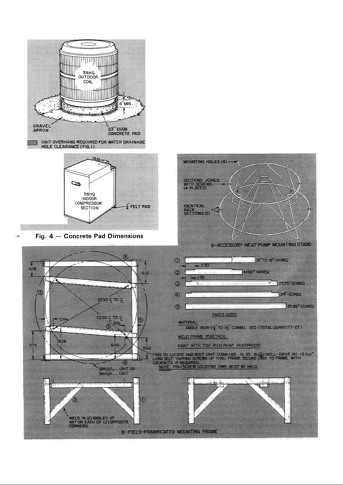
does not obstruct drainage holes (holes drain water
during heating and defrost cycles). Attach unit to
pad with 1/4-in. mounting bolts. Position tiedown
bolts in pad. Any 2 holes in unit basepan may be
used to fasten unit to pad.
Construct round, 23-in. diameter pad a mihimum
of 6 in. above grade to provide clearance under holes
for drainage and ice build-up. In areas where pro
longed subfreezing temperatures or heavy snows
occur: increase clearance from 12 to 18 in. by con
structing an angle-iron frame to support unit 12 to
18 in. off concrete base. Cross angle of frame must
not obstruct coil drainage holes. See Fig. 5 for
recommended frame construction. Extend a 12-in.
gravel apron around pad for condensate and defrost
water drainage field.
Fig. 5 — Mounting the Outdoor Coil
4
Since it is lightweight, the outdoor unit can be
mounted on a platform attached to or built out from
structure. Construct platform using drainage and
clearance recommendations above. Locate and con
struct platform to avoid possible transfer of unit
vibration to structure.
ON THE ROOF: MOUNT OUTDOOR COIL ON
A LEVEL PLATFORM OR FRAME. Unit must
be elevated for proper clearance as described
under ground installation above. Roof design and
water drainage must be planned to prevent units
from setting in water. Flash all roof openings to
prevent leaks.
Step 3 — Mount Indoor Compressor Section
on a rigid, solid platform or concrete floor. Insert
1/4-in. asphalt impregnated felt pad (factory
supplied) between unit basepan and mounting
surface to provide full unit support and for vibra
tion attenuation. (Do not use vibration isolator
under corners of basepan.)
Step 4 — Make Piping Connections — The
38HQ units can be connected to indoor fan coil
using Carrier accessory tubing package or field-
supplied tubing of refrigerant grade. See Tables 1
and 2 (with notes) for unit piping connection type,
size and line size recommendations and Table 4 for
accessory tubing sizes. Maximum allowable system
liquid line length is 100 feet. Maximum vapor line
length from compressor section to indoor coil is 50
feet. Maximum vapor line length from eompressor
section to outdoor coil is 50 feet.
A capacity reduction will result if accessory
tubing is used in 38HQ146 systems. For example,
when a 25-ft, 7/8-in. accessory tubing package is
used, there will be a capacity reduction of 1-1/2%.
For maximum capacity, use 1-1/8 in. vapor line as
recommended in Tables 1 and 2.
When other than 25 ft of interconnecting piping
is used, follow special requirements described in
Refrigerant Charging. Do not use less than 10 ft of
liquid line. Do not cut accessory 7/8-in. vapor line.
Bend or coil to fit.
Do not use damaged or contaminated tubing.
Always evacuate or purge indoor coil, compressor
section and tubing system (use field-supplied refrig
erant, not unit refrigerant).
When making tubing conneetions, be sure to pro
vide clearance at unit for electrical connections and
follow tubing isolation method. Step 1, page 3.
Table 4 — Accessories
PART WO
38CQ900081
38CQ900111
38CQ900211
38CQ900152
38HQ900011
38CQ900172
38RQ900091
38RQ900032 Outdoor Thermostat — adjustable control for strip heaters, 48-in long Cap Tube
38HÛ900002
38RQ900012
38RQ900072
38RQ900081
28VQ900011
TUBING PACKAGES
38LS934151
38LS934201
38LS934251
38LS934301
38LS934351
38LS934401
38LS934501
38LS978151
38LS978201
38LS978251
38LS978301
38LS978351
38LS978401
38LS978501
‘Swaged at each end down to 3/4 i
fCapacity reduction may occur when
Honeywell Thermostat and Subbase — Automatic Changeover
Honeywell Thermostat and Subbase — Manual Changeover
White Rodgers Thermostat and Subbase — Manual Changeover
Solid State Time Guard 1
Hot Shot Domestic Water Pre-Heater
Optimizer Control (six 38CQ900161, ref HH22AQ110)
Optimizer II Control (use with Outdoor Thermostat HH22AG110)
Outdoor Thermostat — adjustable control for strip heaters; 36-in long Cap Tube
Supplemental Heat Relay (six 38RQ900001 )
Heat Pump Mounting Stand (six 38RQ900061)
Biflow Liquid Filter-Drier (six KH45LD077)
Twelve 3/4- x 1-1/8 in Connection Adapters for 38HQ146
LENGTH
(ft)
15
20
25
30
35
40
50
15
20
25
30
35
40
50
nch
7/8-in accessory tubing is used on 38HQ146
24 V (six 38CQ900141)
LIQUID LINE SUCTION LINE
OD (in.)
3/8
3/8
DESCRIPTIOW
TUBING
OD (in.)
3/4
7/8*t
COMPRESSOR
SECTION 38HQ
120, 127, 134
140, 146
5
REPLACE THE ACCURATER™ REFRIG
ERANT CONTROL PISTON IN THE INDOOR
AND OUTDOOR COIL AS REQUIRED before
connecting refrigerant lines. See Table 3 and the
notes under the table for the pistons used in the
different system combinations. For piston replace
ment instructions, see AccuRater Servicing on
page 16.
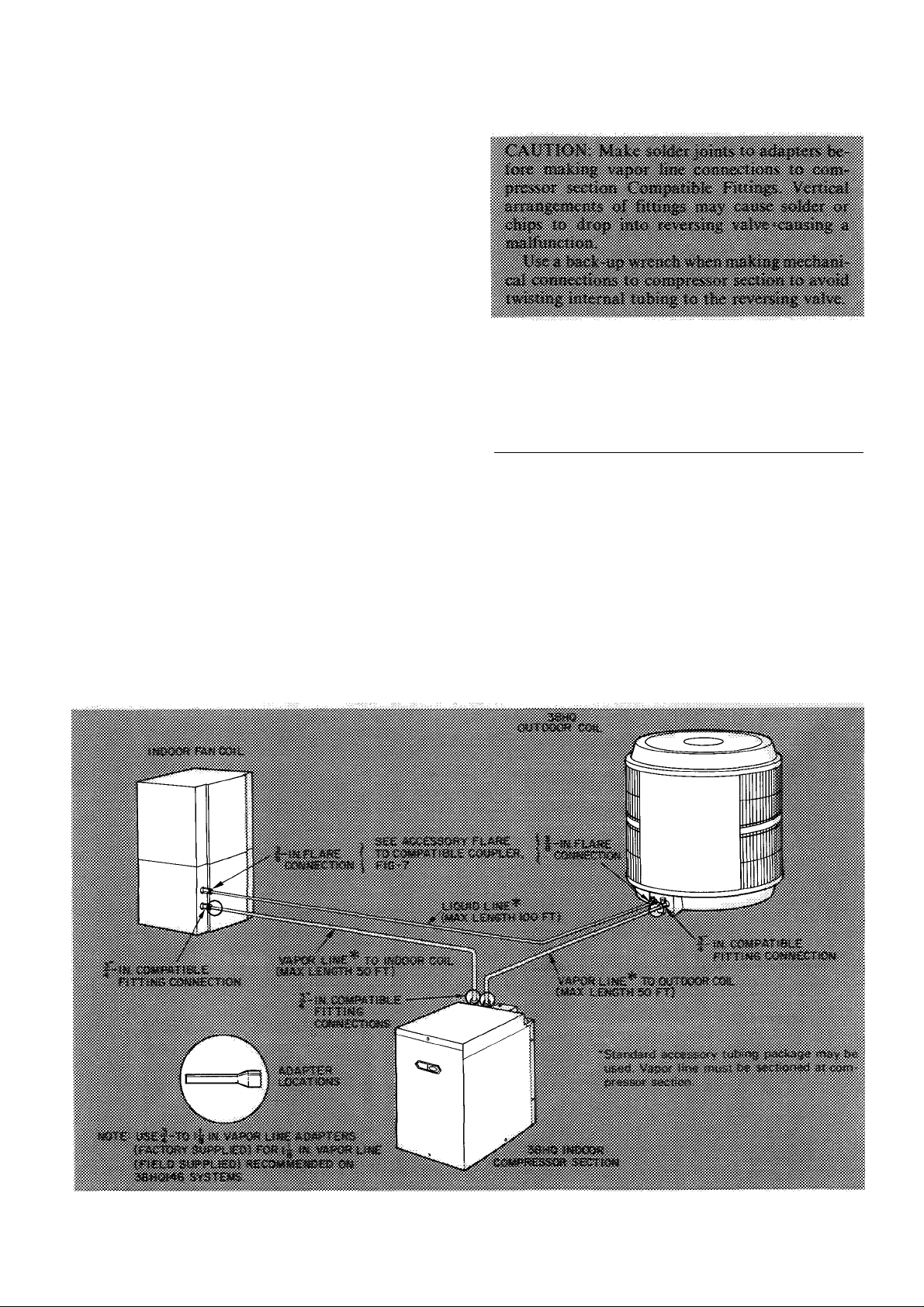
CONNECT REFRIGERANT LINES to fittings on
indoor and outdoor sections, Fig. 1,2 and 6. Indoor
compressor section has 2 Compatible Fitting vapor
line connections. Outdoor coils and indoor fan coils
have Compatible Fitting vapor line connection and
liquid line flare connection.
Connect vapor line from outdoor coil to indoor
compressor section, and from compressor section
to indoor fan coil. Section vapor line as required
(Fig. 6). Use correct compressor section vapor line
connection to indoor fan coil and outdoor coil.
Unit Compatible Fitting(s) permits mechanical or
sweat connection as described below.
When using 1-1/8 in. field-supplied vapor line
(38HQ146 Systems^ remove vapor line adapters (4)
shipped in compressor section. Sweat connect 1-1/8
in. end of adapter to each end of vapor lines. Con
nect 3/4-in. end of adapters to vapor line Com
patible Fitting(s) on outdoor coil, indoor
compressor section and indoor fan coil.
When a 7/8-in. field-supplied vapor line is used
on 38HQ140, 4 field-supplied 3/4-in. to 7/8-in.
vapor line adapters must be provided (not required
if 7/8-in. 38CQ accessory tubing is used).
Flare and connect liquid line from outdoor
coil to indoor fan coil. (Do not disassemble
AccuRater.) It is not necessary to flare system
liquid line if an accessory flare-to-Compatible
Fitting Coupler is used for liquid line connec
tion. See Accessory Coupler, Fig. 7.
Mechanical Connection to Compatible Fitting
(Mate one set of connections at a time.)
1. Loosen nut on Compatible Fitting one turn. Do
not remove.
2. Remove plug and be sure O-ring is in the groove
inside the Compatible Fitting.
3. Cut tubing to correct length.
4. Insert tube into Compatible Fitting until it
bottoms.
5. Tighten nut until it bottoms on back coupler
flange. Keep tube bottomed in Compatible
Fitting while tightening nut.
Fig. 6 — Refrigerant Piping Connections

Field wiring must comply with local and national
fire, safety and electrical codes. Voltage to units
must be within ± 10% of voltage indicated on
nameplate. Contact local power company for cor
rection of improper line voltage.
Fig. 7 — Accessory Coupler
Sweat Connection to Compatible Fitting (Use
refrigerant grade tubing.)
1. Remove locking nut, rubber O-ring and Schrader
core from valve.
2. Cut tubing to correct length.
3. Insert tube into Compatible Fitting. Wrap top
and bottom of service valves in wet cloth to
prevent damage by heat. Solder with low-
» temperature (430 F) silver alloy solder.
4. Replace Schrader core.
5. Evacuate or purge system with field-supplied
refrigerant.
Accessory Flare-to-Compatible Coupler is shown in
Fig. 7. Attach flare nut on coupler to flare fitting on
unit liquid line connection. Connect liquid line to
Compatible Fitting using mechanical or sweat
connection. When mechanical connection is made,
use 2 wrenches when tightening Compatible Fitting
nut — one to hold coupler and one to tighten nut.
Liquid line must be flared if coupler is not used.
Step 5 — Make Electrical Connections
When making electrical connections, provide
clearance at unit for refrigerant piping connections.
See Table 5 for recommended wire and fuse sizes.
Line and control power wiring for 38HQ outdoor
coil are from connections in the 38HQ compressor
section. Line power wire size to outdoor coil section
must be 14 gage minimum when total wire length
connecting compressor section to coil is under 25
feet. If over 25 ft, use same wire size as compressor
section branch circuit.
INSTALL A BRANCH CIRCUIT DISCONNECT
per NEC of adequate size to handle compressor
section starting current. Provide a separate discon
nect switch for outdoor coil section. Provide a
separate disconnect per NEC for indoor fan coil and
for each accessory electrie heater circuit as required.
(See Indoor Unit and Electric Heater Installation,
Start-Up and Serviee Instructions.) Locate dis-
connect(s) within sight of and readily accessible to
the unit, per section 440-14 of National Electrical
Code (NEC).
BRING LINE POWER LEADS INTO COM
PRESSOR SECTION — Extend leads from dis
connect per NEC thru 1-1/8in. hole provided in
compressor section top panel (Fig. 2) and into eontrol box. Extend line power leads for outdoor eoil
section thru 7/8-in. hole provided in compressor
section top panel and into control box.
Table 5 — Electrical Data (60-Hz)
INDOOR
COMPR
SECTION
120 940
127
134
140
146 960
AWG — American Wire Gage
FLA — Full Load Amps
HACR — Heating, Air Conditioning & Refrigeration
ICS — Indoor Compressor Section
LRA — Locked Rotor Amps
MCA — Minimum Circuit Amps
OC — Outdoor Coil
OFM — Outdoor Fan Motor
RLA — Rated Load Amps
‘Permissible limits of the voltage range at which the unit will
operate satisfactorily
OUTDOOR
38HQ
COIL
940
940
960
V/PH
230/1
OPER
VOLTAGE*
Max
Min
254
207
FLA
1 5 10
Min Wire
Size
(AWG)t
12
fCopper wire sizes based on 60C Use copper or copper-clad
^Required when using non-metallic conduit
“Outdoor Coil Wiring — For 25-ft wire run or less, use minimum
ttMaximum dual element size
NOTE All units have 24-v control circuit which requires external
power source
COMPR
LRA
65 103 1 5
72
88 20 0 1 5 10 14t
94 21 7 2 3 8
106
OFM
RLA ICS
17 1
27 9 2 3 8
BRANCH CIRCUIT
25t
Min Gnd
Wire
Sizef*
OC
10
14t
Max Fuse or
HACR Type
Ckt Brk Ampstt
20 164
40
45
50 30 7
60
MCA
22 7
26 7
37 2
Max Ft
Wire
OC ICS OC ICS
50
50
43
58
50
aluminum wire only Use latest NEC for copper-clad aluminum
conductor sizing
14 AWG wire size For longer wire run, use same size wire as
supply to compressor section

CONNECT GROUND LEADS AND POWER
WIRING
Connect ground leads to the ground lug in
control box for safety. Connect power wiring. See
Fig. 8. Splice compressor section line power leads
to yellow and black pigtails, and outdoor coil power
leads to brown and blue pigtails. Use wire nuts and
tape each connection.
CONNECT POWER LEADS FROM INDOOR
COMPRESSOR SECTION TO OUTDOOR
COIL thru outdoor disconnect switch. From dis
connect switch extend leads thru hole provided in
coil basepan (Fig. 1) and into line voltage section
of junction box, Fig. 24. Splice leads to black and
blue pigtails with wire nuts.
SEE INDOOR FAN COIL AND ELECTRIC
HEATER INSTALLATION, START-UP AND
SERVICE INSTRUCTIONS for line power wiring
details. All control wiring connections are shown
in this booklet.
CONNECT CONTROL POWER WIRING (24 v)
— Extend wiring thru 7/8-in. grommeted hole in
compressor section top panel (Fig. 2), and to control
wiring terminal board on side of control box. Con
nect leads to terminal board as shown in Fig. 9.
Extend and connect control wiring from compressor
section to outdoor coil as required. Make splice
connections in low voltage section of coil junction
box.
Use indoor fan coil transformer as 24-v supply for
system. At least a 60-va transformer is recom
mended. Carrier approved indoor units are
equipped with a 60-va transformer. See Indoor
Unit data.
Use Carrier accessory indoor thermostat with
subbase. Table 4.
START-UP
The 38HQ Indoor Section Compressor is
equipped with a crankcase heater. It is recom
mended that heater be energized a minimum of 24
hours before starting unit. To energize heater only,
turn the thermostat to OFF position and close
electrical disconnect to heat pump.
Heat Anticipator Settings for Room Thermo
stat (HH07AT071) — Set anticipator settings for
room thermostat according to Table 6. These
settings may be changed slightly to provide a greater
degree of comfort for a particular installation.
> Table 6 — Thermostat Anticipator Settings
INDOOR
COMPR
SECTION
OUTDOOR
COIL
38HQ
120
127
134 940 Fixed
140 960
146 960
940
940
FIRST-
STAGE
ANTICI
PATOR
SETTING
INDOOR
UNIT WITH
ELECTRIC
HEATER
40AQ
Fan Coil
with 7 5
40AQ Htrs
40FS/28HO,VQ
with 40FQ
Htrs
40QB Fan Coil
with 40QB Htrs.
HTR
KW
10.0
12 0
15 0
20 0
25 0
30 0
5 0
SECOND-
STAGE
ANTICI
PATOR
SETTINGS
(Ampi
25
50
75
Accessory Outdoor Thermostat provides adjust
able outdoor control of accessory electric heater
(used on indoor fan coil). This thermostat makes
contact when a drop in outdoor temperature occurs.
It energizes a stage of electric heat when the outdoor
temperature setting is reached, provided the room
thermostat is on the second stage of heating. One
outdoor thermostat is recommended for each stage
of electric heat after the first stage. Set the outdoor
thermostat(s) progressively lower for each stage.
Refer to heat load of building and unit capacity to
determine the correct outdoor thermostat settings.
> The accessory supplemental heat relay is required
when 2 outdoor thermostats are used. It is auto-
FACTORY WIRING
Fig. 8 — Line Power Connections
8

THERMOSTAT 40AQ OR 40QB FAN COIL 38HQ
SUBBASE COOLING CONTROL COMPRESSOR
HH93AZ073 OR KIT SECTION
HH93AZ075 TERMINAL BOARD TERMINAL BOARD
TH ERMOSTAT 40AQ OR 40 FQ
SUBBASE ELECTRIC HEATER
HH93AZ0730R TERMINAL
HH93AZ075 BOARD
38HQ
COMPRESSOR
SECTION
TERMINAL BOARD
38HQ
OUTDOOR COIL
JUNCTION BOX
(38HQ/40AQ OR 40QB WITHOUT ELECTRIC HEATER)
COOLING AND ONE-STAGE HEATING
A
THERMOSTAT 40AQ, 40QB OR 40FQ 38HQ
SUBBASE ELECTRIC HEATER COMPRESSOR
HH93AZ073 0R TERMINAL SECTION
HH93AZ075 BOARD TERMINAL BOARD
COOLING AND TWO-STAGE HEATING
(38HQ WITH 40AQ,40QB OR 40FS/28HQ/VQ
EQUIPPED WITH ELECTRIC HEATER-,
SUPPLEMENTAL HEAT, NO OUTDOOR THERMOSTATS)
B
THERMOSTAT 40AQ.40QB 0R40FQ 38HQ
SUBBASE ELECTRIC HEATER COMPRESSOR
HH93AZ073 0R TERMINAL SECTION
HH93AZ075 BOARD TERMINAL BOARD
COOLING AND TWO-STAGE HEATING
(38HQWITH 40FS/28HQ/VQ
EQUIPPED WITH ELECTRIC HEATER;
SUPPLEMENTAL HEAT, TWO OUTDOOR THERMOSTATS)
THERMOSTAT 40DQ
SUBBASE ELECTRIC HEATER
HH93AZ073 TERMINAL SPLICE
OR HH93AZ075 CONNECTIONS
&
ORN
&
&
&-
BRN
_vio__^
38 HQ
COMPRESSOR SECTION
TERMINAL BOARD
0&
[IF
COOLING AND TWO-STAGE-STAGE HEATING
(38HQ WITH 40DQ EQUIPPED WITH ELECTRIC HEATER
WITH TRANSFORMER, SUPPLEMENTAL HEAT,
NO OUTDOOR THERMOSTAT
DFT — Defrost Thermostat
EHR — Supplemental Heat Relay
ODT — Outdoor Thermostat
------------
Factory Wiring
-----------
Field Wiring
COOLING AND TWO-STAGE HEATING
(38HQ WITH 40AQ, 40QB OR 40FS/28HQ/VQ
EQUIPPED WITH ELECTRIC HEATER;
SUPPLEMENTAL HEAT, ONE OUTDOOR THERMOSTAT
Fig. 9 — Control Circuit Connections
matically energized by the manually operated sup
plemental heat switch in the indoor thermostat
subbase. The thermostat locks out compressor and
the relay bypasses the outdoor thermostats for
electric heater operation during heat pump shut
down. When one outdoor thermostat is used, a
supplemental heat relay is not required. The supple
mental heat switch in the indoor thermostat subbase
bypasses outdoor thermostat, locks out compressor
and activates electric heater.
MOUNT OUTDOOR THERMOSTAT(S) —
Locate maximum of 2 outdoor thermostats in
control voltage section of outdoor coil junction box.
Fasten in place with sheet metal screws.
*Transformer (60 va) located in cooling control kit or electric heater
fTerminal L is identified as terminal X on some former thermostats
(Required for system malfunction warning indicator on com
pressor section )
{Remove 1 or both factory-installed jumpers (connection B) when
installing outdoor thermostats (ODT) shown in connections C
and D
MOUNT SUPPLEMENTAL HEAT RELAY in
convenient location on indoor unit. Attach with
sheet metal screw.
To Start System — (Be sure crankcase heater has
been energized for 24 hours.) Adjust the thermo
stat as follows:
1. Set selector switch at OFF.
2. Turn on main disconnect switch(es) to indoor
and outdoor units.
3. Set fan switch as desired (ON or AUTO.).
4. Set thermostat dial at desired temperature.
5. Set selector switch at HEAT or COOL.
Check system refrigerant charge. See Refrigerant
Charging.

SERVICE
’■Refrigerant Charging — The 38HQ940 outdoor
coil contains a factory charge of 7.1 lb of R-22; the
38HQ960 outdoor coil contains a factory charge of
10.0 lb. This charge is correct for all systems except
those listed in Table 7. When the amount of refrig
erant shown in Table 7 is added, the final charge will
agree with the amount stamped on the compressor
section nameplate.
> Table 7 — Refrigerant Charging Data
INDOOR
COMPRESSOR
SECTION
38HQ120
38HQ127 38HQ940
38HQ134
38HQ140
38HQ146
OUTDOOR
COIL
38 H0940
38HQ940
38HQ960
38HQ960
INDOOR
FAN COIL
40AQ030
28HQ.VQ030
40AQ036
28HQ,VQ036
40AQ036
28HQ,VQ036
28HQ,VQ036
40AQ036
28HQ,VQ042
40QB042
28HQ,VQ048
40QB048
AMOUNT OF
R-22 TO BE
ADDED (oz)
I 7
7
15
15
8
8
14
14
19
27
19
27
The above charges are suited to systems with 25 ft
of recommended tubing. Adjust system charge for
refrigerant line lengths and diameters that differ
from 25 ft and 3/8-in. OD (liquid line), respectively,
using refrigerant weights shown in table below.
(Twenty-five feet of 3/8-in. OD tubing contains
14.4 oz of R-22.) Add R-22 charge to system if liquid
line is over 25 ft; remove charge if liquid line is
shorter than 25 feet.
LIQUID LINE
DIAM (in.)
3/8
5/16
1/4
OUNCES OF R-22/FT LENGTH
OF LIQUID LINE
58
36
21
When recharging is necessary during heating or
cooling season, weigh in total charge indicated in
Table 8. (Charge must be weighed in during heating
season.) Remove any refrigerant remaining in sys
tem before recharging. If system has lost complete
charge, evacuate system to 500 microns (29.7 in.
vacuum) before recharging. Service port connec
tions are provided on indoor compressor section
suction and discharge lines for evacuation and
charging. (See Fig. 24 for service port locations.)
Dial-a-charge charging cylinder is an accurate
device used to recharge systems by weight. These
cylinders are available at refrigeration supply firms.
To check and/or adjust charge during cooling
season, use correct Cooling Cycle Charging Chart
(Fig. 10 thru 16) and follow Charging Chart Method
below. The charging chart may also be used as an
alternate method of recharging system.
To check system operation during heating cycle,
use correct Heating Cycle Operation Check Chart
(Fig. 17 thru 23). These charts indicate whether a
correct relationship exists between system operating
pressures and air temperatures entering indoor and
outdoor units. If pressure and temperature lines do
not intersect on chart, the system refrigerant charge
may not be correct or other system abnormalities
may exist. Do not use Operation Check Charts to
adjust refrigerant charge. Weigh charge into system.
COOLING CYCLE CHARGING CHART
METHOD
1. Operate unit a minimum of 10 minutes before
checking charge, and after each charge
adjustment.
2. Measure suction pressure by attaching a gage to
indoor unit suction service port. (See Fig. 24 for
correct service port location.)
3. Measure outdoor (coil inlet) air dry-bulb tem
perature with service thermometer.
4. Using a sling psychrometer, measure wet-bulb
temperature of air entering indoor fan coil.
5. Refer to correct Charging Chart. Locate on
curves where outdoor air dry-bulb and indoor air
wet-bulb temperature lines intersect.
'-N
Table 8 — Service Data
INDOOR COMPR
SECTION 38HQ
REFRIG
COMPR MODEL*
Oil Rechg (oz)
OUTDOOR
COIL
R-22 CHG (lb)t
FAN
Cfm
Rpm
Diameter (in.)
Motor Hp
*Refer to Service Parts catalog for replacement compressor model numbers
fFactory-supplied charge in outdoor unit for complete system Charge adjustment may be required on some systems See Table 7
MD2013HB
7 5
783
46
120 j 127
MD2713HB
46
38 H0940
7.1t
Propeller — Direct Drive
10
134 140 146
R-22
MD3413HB
46
7 1
3100 1 3600
1015 1080
20 20
1/5 1/4
PC4616AD ! PC5316AD
76 1 76
38HQ960
100

REFRIGERANT CHARGING AND CHECK CHARTS
r.
Fig. 10 — 38HQ120/38HQ940 with
40AQ030 or 28HQ.VQ030 Cooling Cycle
Charging Chart (R-22)
Fig. 12 — 38HQ127/38HQ940 with
40AQ030 or 28HQ,VQ030 or 40DQ030
Cooling Cycle Charging Chart (R-22)
Fig. 11 — 38HQ120/38HQ940 with
40AQ036 or 28HQ,VQ036 or
40FS160/28HQ.VQ036 Cooling Cycle
Charging Chart (R-22)
SUCTION PRESSURE AT COMPRESSOR SERVICE PORT (PSIG)
Fig. 13 — 38HQ127/38HQ940 with
40AQ036 or 28HQ,VQ036 or
40FS160/28HQ,VQ036 Cooling Cycle
Charging Chart (R-22)
11

Fig. 14 — 38HQ134/38HQ940 with
40AQ036 or 28HQ,VQ036 or 40FS160/
28HQ,VQ036 Cooling Cycle Charging Chart
SUCTION PRESSURE AT COMPRESSOR SERVICE PORT (PSI6)
Fig. 16 — 38HQ146/38HQ960 with
28HQ,VQ048 or 40FS200/28HQ.VQ048 or
40FS220/28HQ,VQ048 or 40QB048
Cooling Cycle Charging Chart
SUCTION PRESSURE AT COMPRESSOR SERVICE PORT (PSIG)
Fig. 15 — 38HQ140/38HQ960 with
28HQ,VQ042 or 40FS160/28HQ.VQ042 or
40FS200/28HQ,VQ042 or 40QB042
Cooling Cycle Charging Chart
320r
280 +
260
830 cfm,70F db
I tit WET-BULB TEMP.
^AIR ENT
OUTDOOR UNIT (F)i
+!-rr
2A0t
i]tl
IW
-y|ifini
to/;
i/ièi
1 1
.j
1 1 Tr
i/H
M
^DRY-BULB TEMP. -
•AIR ENT INDOOR -
:
J:!-! L
ti'tL
:'t‘i
ItH
: 'r-‘- r
i
'kT
H-H:
a; 220-
'iTii
1 ; Til
#rr
'iffl
f
Tttr
'ifr
^iiii
"Til!“
160^
Wt
140
10 20 30 40 50 60 70 80 90 100 110 120 130 140
SUCTION PRESSURE AT COMPRESSOR SERVICE PORT (PSIG)
: t\±\
t H-
Kir
Tilt
|4
H-ff
ilit
tl ri
II#
li-ij
r;;r
irtt
##L
UL .- i
-fin p+t
1
Iti:
-ìi
-rt^!
Ttfl
ibi:
Ì r
Fig. 17 — 38HQ120/38HQ940 with
40AQ030 or 28HQ.VQ030 Heating Cycle
Operation Check Chart
r’TT
=[f!l
-K-r
i - -
k|:
Hit
■ ~ ’ L
; V j_
; i ■#
:tr#
t:H
1
= 1 i ‘
¡rtj r
i ■ ■ 1
Kti
ri d-
■ 1
: i ■ ■
-d
Ttfl-
-i_Ll i,
r^r
H
Ì
.
j
12

Fig. 18 — 38HQ120/38HQ940 with
40AQ036 or 28HQ.VQ036 or
40FS160/28HQ,VQ036 Heating Cycle
Operation Check Chart
Fig. 20 — 38HQ127/38HQ940 with
40AQ036 or 28HQ,VQ036 or
40FS160/28HQ,VQ036 Heating Cycle
Operation Check Chart
Fig. 19 — 38HQ127/38HQ940 with
40AQ030 or 28HQ,VQ030 or 40DQ030
Heating Cycle Operation Check Chart
Fig. 21 — 38HQ134/38HQ940 with
40AQ036 or 28HQ,VQ036 or
40FS160/28HQ,VQ036 Heating Cycle
Operation Check Chart
13

VAPOR LINE
CONNECTIONS
RUN CAPACITOR
SUCTION LINE'
COMPRESSORTERMINAL BOX
CONTROL WIRING
TERMINAL BOARD
CONTROL BOX
COMPRESSOR
38HQ INDOOR
COMPRESSOR
SECTION
LEFT SIDE VIEW
Fig. 22 — 38HQ140/38HQ960 with
28HQ,VQ042 or 40FS160/28HQ.VQ042 or
40FS200/28HQ,VQ042 or 40QB042
Heating Cycle Operation Check Chart
SUCTION LINE
ACCUMULATOR
CRANKCASE HEATER
COMPRESSOR HOLD
DOWN BOLTS (3) OR (4)
RIGHT SIDE VIEW COMPRESSOR SECTION
38HQ INDOOR
TOP GRILLE
COVER
ERVICE DOOR
Fig. 23 — 38HQ146/38HQ960 with
28HQ,VQ048 or 40FS200/28HQ,VQ048 or
40FS220/28HQ.VQ048 or 40QB048
Heating Cycle Operation Check Chart
CONTROL
VOLTAGE
SECTION
DEFROST
THERMOSTAT
LIQUID LINE SERVICE
VALVEiWITH SERVICE PORT)
VAPOR LINE SERVICE VALVE
(WITH SERVICE PORT)
14
38HQ OUTDOOR COIL SECTION
Fig, 24 — Component Location

6. From intersect point, project vertically down
ward to chart suction pressure line. Compare
chart suction pressure to unit suction pressure
(Step 2).
7. If unit suction pressure is lower than chart
pressure, add refrigerant to system until chart
pressure is reached. If unit suction pressure is
higher than chart pressure, remove refrigerant
until chart pressure is reached.
Unit Single-Phase Compressors that are
Equipped with a Compressor Start Thermistor
(PTC device) — When supply voltage is within 10%
limit and compressor does not start, check the start
thermistor with an ohmmeter.
If PTC resistance is 0 ohm (open) or higher than
200% of the rating, the device is defective.
Compressor Removal — See Table 8 for com
pressor information and Fig. 24 for component
location.
Remove refrigerant from system using refrigerant
removal methods described in Carrier Standard
Service Techniques Manual, Chapter 1.
Follow safety codes, and wear safety glasses and
work gloves. Have quenching cloth available.
1. Remove unit top cover and front access
wrapper.
2. Remove compressor terminal box cover, dis
connect and remove compressor power leads.
3. Using a tubing cutter, cut suction and discharge
lines at convenient place near compressor for
easy reassembly to new compressor with copper
slip couplings.
4. Remove crankcase heater from compressor
base.
5. Remove compressor hold-down bolts. Lift out
compressor.
6. Carefully unbraze suction and discharge line
piping stubs from compressor. If oil vapor in
piping stubs ignites, use quenching cloth.
7. Braze piping stubs (removed in step 6) on new
compressor.
8. Clean system. Add new liquid line heat pump
filter-drier as described below.
9. Install new compressor in unit. Braze suction
and discharge lines to compressor piping stubs
(at points where cut, step 3) using fieldsupplied copper couplings. Ensure compressor
hold-down bolts are in place. Connect wiring.
10. Evacuate and recharge system.
FILTER-DRIER — Install accessory heat pump
filter-drier (Table 4) in system liquid line when
refrigerant system is opened for service as described
under Compressor Removal. Position drier in liquid
line at convenient location.
Unit Controls and Safety Devices
HIGH-PRESSURE RELIEF VALVE is located in
compressor. Relief valve opens at a pressure differ
ential of approximately 600 psi between suction
(low side) and discharge (high side) to allow pres
sure equalization.
INTERNAL CURRENT AND TEMPERATURE
SENSITIVE OVERLOAD resets automatically
when internal compressor motor temperature drops
to a safe level (overloads may require up to 45
minutes to reset). When an internal overload is
suspected of being open, check by using an
ohmmeter or continuity tester. If necessary, refer
to Carrier Standard Service Techniques Manual,
Chapter 2, for complete instructions.
LOW-PRESSURE SWITCH is located in com
pressor section on suction line between reversing
valve and accumulator. Provides loss of charge pro
tection by shutting compressor off if suction
pressure drops below setting. Low-pressure switch
settings are: open, 5 ± 3 psig; close, 20 ± 5 psig.
CRANKCASE HEATER is connected across line
side of contactor and operates continuously.
The purpose of the heater is to keep the crank
case warm during the off cycle and thus prevent
dilution of the oil with refrigerant. This assures good
lubrication and prevents loss of oil from crankcase
during start-up.
If the electrical disconnect switch to the com
pressor section has been off for an extended period
of time, the crankcase heater should be energized for
24 hours before starting the compressor.
SYSTEM MALFUNCTION WARNING INDI
CATOR turns on indoor thermostat light if ther
mostat calls for heating or cooling and compressor
doesn’t operate because; low-pressure switch or
internal line break has functioned; control device
or compressor is not operational. The light turns off
when compressor restarts, indoor thermostat is
satisfied or if thermostat is manually turned off,
then on.
15

Fig. 25 — 38HQ Refrigerant Flow Diagrams
DEFROST CONTROL, consisting of a defrost
timer, defrost thermostat and defrost relay, inter
rupts normal system heating operation every 90
minutes to defrost outdoor coil, if the coil saturated
suction temperature indicates freezing tempera
tures. Defrost control simultaneously stops outdoor
fan, energizes reversing valve solenoid to return
system to cooling cycle (outdoor eoil as condenser,
indoor fan coil as evaporator), and activates
accessory electric heater.
For the heat pump to defrost, 2 conditions are
necessary:
->1. Defrost timer switches LI from terminal 6 to
terminal 5.
2. Refrigerant temperature from outdoor unit must
be cold enough to cause defrost thermostat con
tacts to close. Contacts close at 27 ( ± 4) F.
Every 90 minutes of elapsed running time the
defrost timer contacts close for 10 seconds. If the
defrost thermostat contacts are closed, the unit
defrosts. The defrost timer limits defrosting period
to 10 minutes. Normally the frost is removed and
the defrost thermostat eontacts will open to ter
minate defrosting before 10 minutes have elapsed.
Defrost thermostat contacts open at 80 F (± 6)
liquid refrigerant temperature. When defrosting is
terminated, the outdoor fan motor is energized and
reversing valve solenoid is de-energized returning
unit to heating cycle.
HEAT PUMP CIRCUITS shown in Fig. 25 are
refrigerant flow diagrams for heating and cooling
cycles.
Pumpdown Procedure (Cooling Cycle) — The
38HQ units may be pumped down in order to
make repairs on low side of system without losing
complete refrigerant charge.
1. Attach pressure gage to suetion service port.
2. Frontseat the liquid line valve on outdoor coil.
3. Start unit and run until suction pressure reaches
5 psig (see Caution) or low-pressure switch
opens.
4. Shut unit off and frontseat vapor line valve on
outdoor coil.
5. Vent remaining pressure.
AccuRater™ (Bypass Type) Servicing — See
Fig. 26 for bypass type AccuRater components. The
piston has a refrigerant metering hole thru it. The
retainer forms a stop for the piston in the refrig
erant bypass mode, and a sealing surface for liquid
line flare connection. To check, clean or replace
piston:
1. Shut off power to unit.
2. Pump unit down using Pumpdown Procedure
described previously.
3. Remove liquid line flare connection from
AccuRater.
4. Pull retainer out of body being careful not to
scratch flare sealing surface. If retainer does not
pull out easily, carefully use vise grips to
remove retainer.
Fig. 26 — AccuRater (Bypass Type)
Components
16

5. Slide piston out by inserting a small soft wire
thru metering hole (18-gage thermostat wire).
See that metering hole, sealing surface around
piston cones and fluted portion of piston are
, not damaged.
I
6. Clean piston refrigerant metering hole.
7. Replace retainer O-ring before reassembling
bypass type AccuRater™. Carrier O-ring part no.
is 99CC501052.
LIQUID LINE STRAINER protects AccuRater.
Made of wire mesh, it is located in the liquid line
inside indoor fan coil behind liquid line service
valve (Fig. 25). Liquid line is belled and sweat
connected where strainer is located. If strainer is
plugged, unsweat belled liquid line connection and
replace strainer.
Lubrication
COMPRESSOR contains factory oil charge. Re
place oil when lost. See Table 8 for oil recharge.
If necessary, refer to Carrier Standard Service Tech
niques Manual, Chapter 1, page 1-21, for oil
recharging procedure. Use Carrier PP33-1, Texaco
Capella B or Suniso 3G oil.
OUTDOOR FAN MOTOR BEARINGS are pre
lubricated for 3 years heavy duty or 5 years normal
duty. When lubrication is necessary, send motor to
authorized motor repair shop.
Outdoor Coil Cleaning — Ensure power to unit is
shut off. Clean the outdoor coil with water at the
beginning of every cooling season or more often if
required. Use ordinary garden hose at a pressure
high enough to clean efficiently. For best results, un
screw and remove unit top cover (grille).
Insert hose nozzle between fan blades and spray
coil fins from inside-to-outside the unit. If unit has
a double-row coil, loosen screws to separate coils,
pull outer row of coils away from inner row, and
flush dirt toward outside of both coils. Flush dirt
from basepan by spraying water thru top of unit.
Avoid splashing mud on coil or water on the fan
motor. Make sure that water drainage holes under
outdoor coil are not obstructed.
Outdoor Fan Position — Required fan position is
shown in Fig. 27. Adjust fan by loosening setscrews
and moving fan blades up or down.
FAN MOTOR REMOVAL
1. Shut off power to outdoor coil.
2. Remove unit top cover (grille). Open or remove
service door. Remove junction box cover.
3. Disconnect fan motor leads in line-voltage
MAINTENANCE
section of junction box. See Fig. 24.
Fig. 27 — Outdoor Fan Position
4. Remove fan from motor shaft by loosening
setscrews and pulling upward on fan hub.
5. Remove bolt holding fan motor to motor
mounting bracket. Remove motor with wiring
thru top of unit.
To replace motor: place motor on self-positioning
motor mounting bracket and retighten bolt.
Before replacing metal fan, be sure rain shield
>(Fig. 27) is in place on motor shaft. Seal with
Permagum around hub to prevent entry of water
between hub and shaft.
Compatible Fitting Repair
LEAKING MECHANICAL CONNECTION —
Frontseat outdoor section service valves and relieve
refrigerant pressure in tubing and compressor
section. Back locknut off Carrier Compatible
Fitting onto tube. Cut fitting between threads
and seal ring bead shown in Fig. 28. Remove tubing
section remaining in threaded portion of fitting.
Discard locknut.
Fig. 28 — Carrier Compatible Fitting
Clean, flux, and insert new tube end into remain
ing portion of Carrier Compatible Fitting. Wrap
valve base (outdoor unit) in wet rag. Heat and apply
Tow-temperature solder (430 F).
LEAKING SWEAT CONNECTION — Frontseat
service valves and relieve refrigerant pressure
in tubing. Clean and flux area around leak and apply
- low-temperature solder (430 F).
Evacuate or purge indoor fan coil, compressor
section and tubing system. Add refrigerant charge
(see charging instructions).
LEAKING FLARE CONNECTION — Cut and
reflare 3/8-in. system liquid line.
17

TROUBLESHOOTING CHART — COOLING CYCLE

TROUBLESHOOTING CHART — HEATING CYCLE

(
For replacement items use Carrier Specified Parts.
Manufacturer reserves the right to discontinue, or change at any time, specifications or designs without notice and without incurring obligations.
Book14
Tab
5a
5a
Form 38HQ-10SI Supersedes 38HQ-8SI
Printed in U S A 783
7-81 PC 101
CatalogNo 533-814
i
K
 Loading...