

38HK 18-70
38HQ 18-24
1-6 Nomin
Condensing Units
al Tons.
(50/60 Hz)
Insta
Se
llation,
ervice I
Start-
Instruct
Up
and
tions
SAFETY CONSIDERATIONS
Install and servicing air-conditioning equipment
can be hazardous due to system pressure and
electrical components. Only trained and qualified
service personnel should install or service airconditioning equipment untrained personnel may
perform basic maintenance such as cleaning and
replacing filters. All other operations should be
performed by trained service personnel. When
working on air conditioning equipment, observe
safety precautions in literature, and on tags and
labels attached to unit. Follow all safety codes.
Wear safety glasses and work gloves. Use
quenching cloth for brazing operations. Have a fire
extinguisher available. Read these instructions
thoroughly. Consult local building codes and
National Electrical Code (NEC) for special
installation requirements.
CONTENTS
Page
SAFETY CONSIDERATIONS …………………...………… .
INSTALLATION …………………………………….…………
Step 1 — Complete Pre-Installation Checks ……………
• UNPACK UNIT……………………………………………….
• INSPECT SHIPMENT……………………………………….
• CONSIDER SYSTEM REQUIREMENTS………………….
Step 2 — Rig and Mount Unit ……………………………
• MOUNTING ON GROUND…………………………………
• MOUNTING ON WALL…………………………………….
• MOUNTING ON ROOF………………………………………
• RIGGING……………………………………………………..
Step 3 — Complete Refrigerant Piping Connections …
• MAKE PIPING SWEAT CONNECTIONS………………….
• PROVIDE SAFETY RELIEF……………………………….
Step 4 — Make Electrical Connections ………………..
• POWER WIRING……………………………………………
• CONTROL CIRCUIT WIRING………………………………
• CONNECTIONS TO DUCT-FREE FAN COIL UNITS……..
Step 5 — Accessory Installation………………………….
START-UP……………………................................................
SERVICE ……………………………………………………
MAINTENANCE …………………………………………..
WIRING DIAGRAMS……………………………………….
TROUBLESHOOTING ……………………………………. .
1
1
1
1
1
1
3
3
3
3
3
3
3
4
4
4
4
4
5
6
6
7
9
12
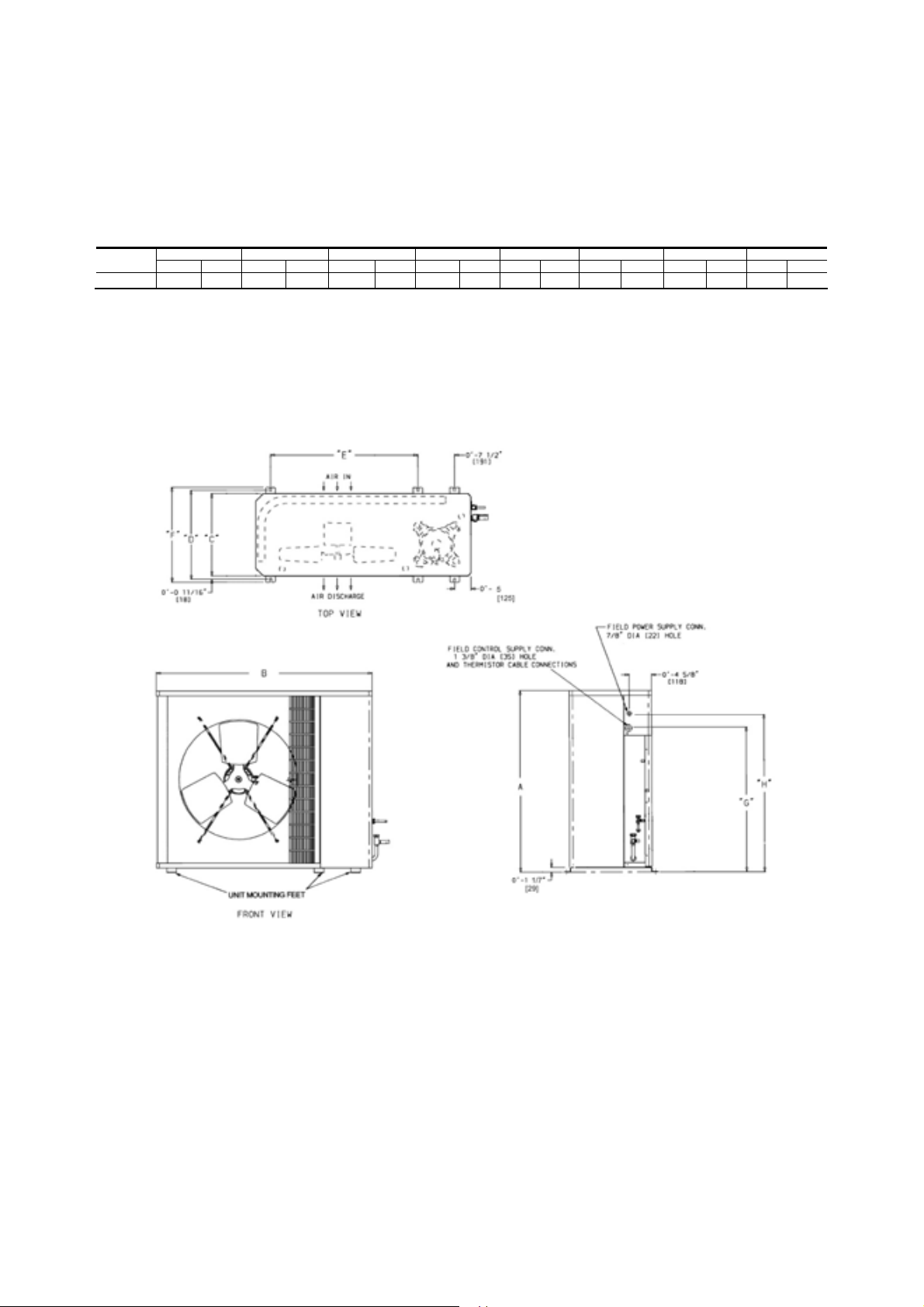
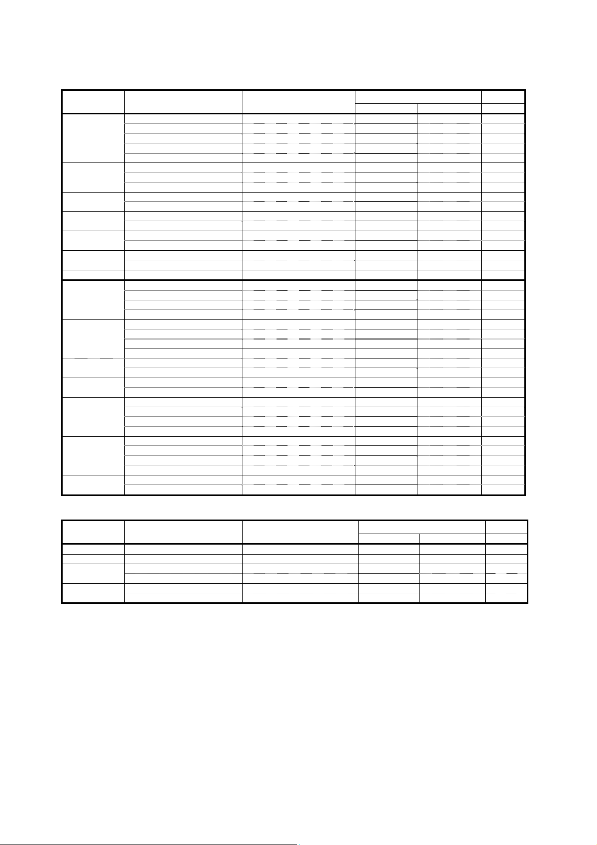
Base Unit Dimensions
38H 01
8-036
6
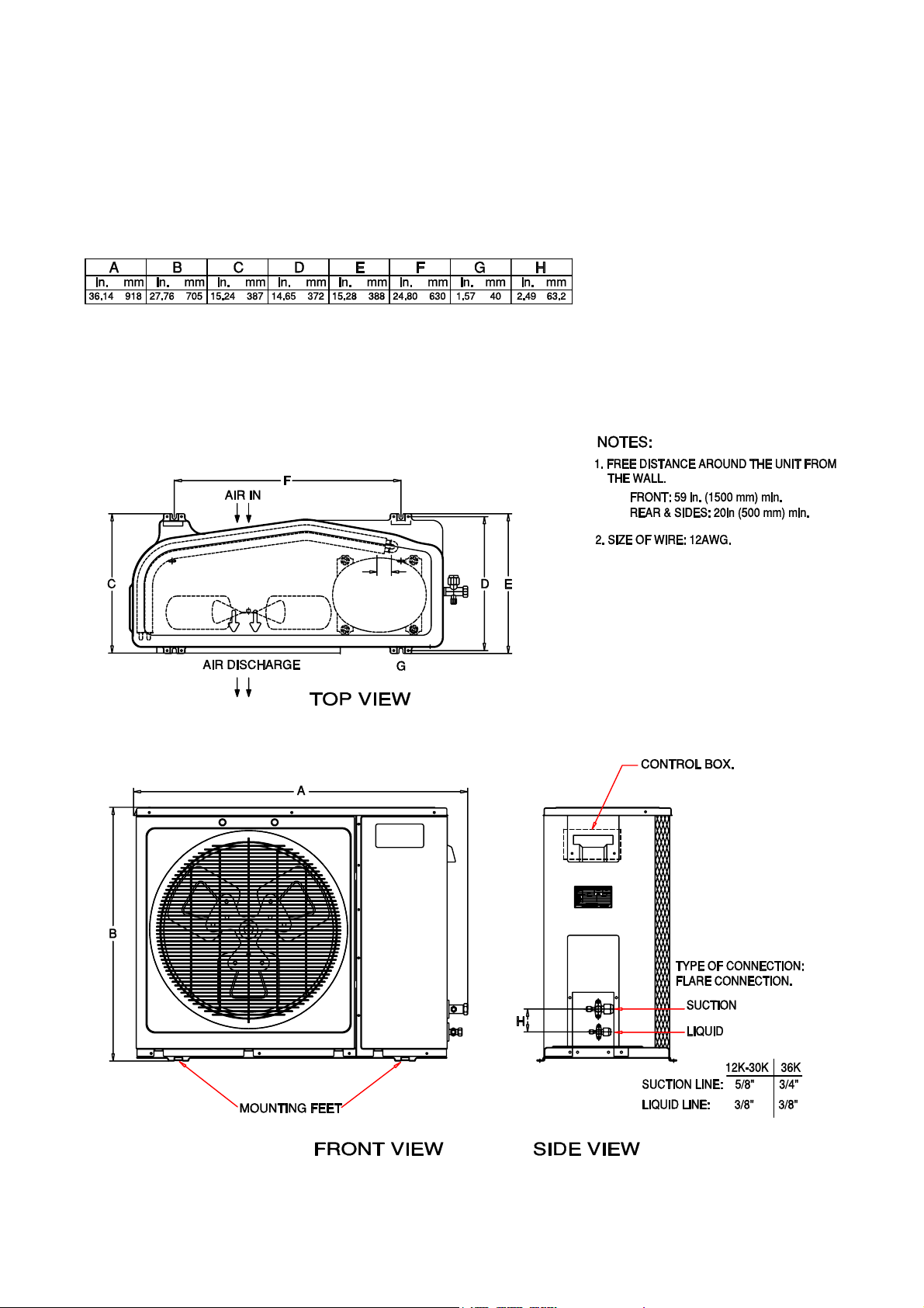
Base Unit Dimensions
38H 048-0
UNIT 38H
048-070
A B C D E F G H
Ft-in. mm Ft-in. mm Ft-in. mm Ft-in. mm Ft-in. mm Ft-in. mm Ft-in. mm Ft-in. mm
3-13⁄16 944.6 3-89⁄16 1131.9 1-51⁄16 433.4 1-67⁄16 468.3 2-61⁄2 774.7 1-75⁄8 498.5 1-75⁄8 498.5 2-55⁄8 752.5
70
NOTES:
1. Required clearances: with coil facing wall
allow 8 in. minimum clearance on coil side and
coil end, and 3 ft minimum clearance on
compressor end and fan side.
2. Dimensions in [ ] are in millimeters.
7
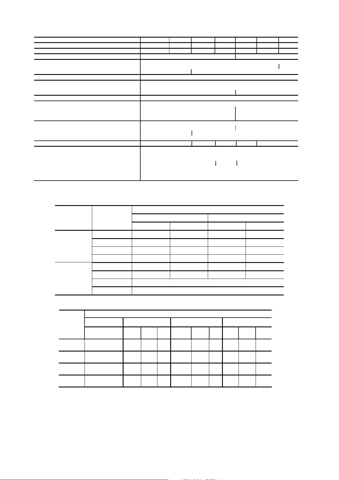
Physical Data
UNIT 38H 18 24 30 36 48 60
NOMINAL CAPACITY (Tons)
OPERATING WEIGHT (lb)
SHIPPING DIMENSIONS (in) (W X H X D)
COMPRESSOR
Heat Pump Rotary --
REFRIGERANT TYPE
METERING DEVICE
Ducted Application Nozzle, in the indoor unit
Un-ducted Application Capillary Tube Nozzle, in the indoor unit
FINISH
OUTDOOR FAN
RPM/CFM 1100/2000 860/3,000
Diameter, No. Blades 18 in, 3 24 in, 3
Motor Horsepower, 1/12 1/3
COIL DATA
Face Area (sq ft) 6.3 12.05
Tubes Smooth Helical grooved
Fins Aluminium, Double Wavy
FPI 15 17 17
REFRIGERANT LINES
Connection Type Flare
Liquid Line 3/8 inch
Vapour Line 5/8 in. 3/4 in. 7/8 inch*
Max Length 50 ft
Max Lift 30 ft
Max Drop 30 ft
* Sweat adapter kit is provided for 7/8” tube size
1.5 2 2.5 3 4.0 5.0
123
139 154 161 211 227
37 x 29.7 x 16.1 50.4 X 40.2 X 30
ReciprocatingCool Only
R22
Gray
Propeller Type
15
12 14
253
Scroll
70
6.0
FREQUENCY INDOOR UNIT
FB4A
60HZ
FREE STAND
42TX
CASSETTE
42TX
50HZ
FB4A
CASSETTE
FREE STAND
COMPRESSOR CHARGE & NOZZLE SIZE
INDOOR
UNIT
MODEL
42TX
FB4A
40GKX
42S/HD-B
VOLTAGE
SIZE 048 060 070 048 060 070 048 060 070
Nozzle Size(in)
Charge (lb)
Nozzle Size(in)
Charge (lb)
Nozzle Size(in)
Charge (lb)
Nozzle Size(in)
Charge (lb)
0.076
10.2 ————
0.084
9.57
0.07
8.73 ————
0.084
10.67
Matching Matrix
38HD
SINGLE PHASE THREE PHASE
SIZE 48 SIZE 60 SIZE 48 SIZE 60
38HD48-3-CF 38HD60-3-CF 38HD48-5-CF 38HD60-5-CF
38HD48-3-CT 38HD60-3-CT 38HD48-5-CT 38HD60-5-CT
38HD48-3-CT — 38HD48-5-CT —
38HD48-3-CT — 38HD48-5-CT —
— — 38HD48-9-CT —
— — 38HD48-9-CF 38HD60-9-CF
TBD
TBD
38HD
208/230-1-60 208/230-3-60 400-3-50
0.088
10.03 ——
0.098
11.86 ——
0.076
10.3
0.084
9.48
0.07
10.75 ——
0.084
10.9
—
—
0.088
9.6 ——
0.098
12.03 ——
——0.076
10.2 ——
0.076
0.088
9.92
9.72 ——
——TBD —
TBD —
—
—
—
—
—
—
—
—
2
LEGEND
- Unit shipped with a holding factory charge of 2.2 lb.
NOTE: Charge based on 25 ft of interconnecting tubing. For longer tube line, add (0.22 lb) for every 10 ft increase in
length.
Electrical Data
COOL ONLY MODELS
Nominal Cap.
MBtuh
18
24
30
36
48
60
70 38HKS70DS90 400/3/50 9.6 82.0 2.3
18
24
30
36
48
60
70
OUTDOOR MODEL Power Supply
38HKC018US70 220-240/1/50 9.7 51.0 1.0
38HKR018US70 220-240/1/50 9.7 51.0 1.0
38HKC018DS70 220-240/1/50 9.7 51.0 1.0
38HKC018US70 220-240/1/50 9.7 51.0 1.0
38HKR018US70 220-240/1/50 9.7 51.0 1.0
38HKC024US70 220-240/1/50 14.0 58.0 1.0
38HKR024US70 220-240/1/50 14.0 58.0 1.0
38HKC024DS70 220-240/1/50 14.0 58.0 1.0
38HKC030US70 220-240/1/50 13.4 85.0 1.0
38HKC030DS70 220-240/1/50 13.4 85.0 1.0
38HKC36US70 220-240/1/50 13.4 85.0 1.0
38HKC36DS70 220-240/1/50 17.0 90.0 1.0
38HKC48US90 400/3/50 6.7 53.0 2.3
38HKC48DS90 400/3/50 6.7 53.0 2.3
38HKC60DS90 400/3/50 9.1 82.0 2.3
38HKC60US90 400/3/50 9.1 82.0 2.3
38HKC018US30 220/1/60 9.6 55.0 0.9
38HKR018US30 220/1/60 9.1 40.0 0.9
38HKC018UP30 220/1/60 9.6 55.0 0.9
38HKC018DS30 220/1/60 9.6 55.0 0.9
38HKC024US30 220/1/60 12.5 60.0 0.9
38HKR024US30 220/1/60 10.1 53.0 0.9
38HKC024UP30 220/1/60 12.5 60.0 0.9
38HKC024DS30 220/1/60 12.5 60.0 0.9
38HKC030US30 220/1/60 13.5 82.0 0.9
38HKC030DS30 220/1/60 13.5 82.0 0.9
38HKC036US30 220/1/60 14.4 88.0 0.9
38HKC036DS30 220/1/60 14.4 88.0 0.9
38HKC048US30 220/1/60 18.5 118.0 2.1
38HKC048US50 220/3/60 11.4 78.0 2.1
38HKC048DS30 220/1/60 18.5 118.0 2.1
38HKC048DS50 220/3/60 11.4 78.0 2.1
38HKC060US30 220/1/60 26.6 178.0 2.1
38HKC060US50 220/3/60 15.0 114.0 2.1
38HKC060DS30 220/1/60 26.6 178.0 2.1
38HKC060DS50 220/3/60 15.0 114.0 2.1
38HKS070DS50 220/3/60 16.0 150.0 2.1
38HKS070DS20 380/3/60 8.3 75.0 2.1
Heat Pump
Nominal Cap.
MBtuh
18 38HQR018US70 220-240/1/50 9.7 51.0 1.0
24 38HQR024US70 220-240/1/50 14.0 58.0 1.0
18
24
OUTDOOR MODEL Power Supply
38HQR018US30 220/1/60 9.1 40.0 0.9
38HQR018UP30 220/1/60 9.1 40.0 0.9
38HQR024US30 220/1/60 10.1 53.0 0.9
38HQR024UP30 220/1/60 10.1 53.0 0.9
Compressor Fan
FLA LRA FLA
Compressor Fan
FLA LRA FLA
3
INSTALLATION
Step 1 — Complete Pre-Installation Checks
UNPACK UNIT—Move unit to final location. Remove
carton from unit, being careful not to damage service
valves or grilles.
INSPECT SHIPMENT — File claim with shipping
company if shipment is damaged or incomplete. Check
unit nameplate to ensure unit matches job requirements.
CONSIDER SYSTEM REQUIREMENTS — Consult
local building codes and NEC for special installation
requirements. Allow sufficient space for airflow
clearance, wiring, refrigerant piping, and servicing unit.
See Fig. 1 and 2. Unit can be mounted on a level pad
directly on base legs or mounted on raised pads at
support points.
WARNING
Before installing or servicing system, always turn off
main power to system.
Step 2 — Rig and Mount Unit
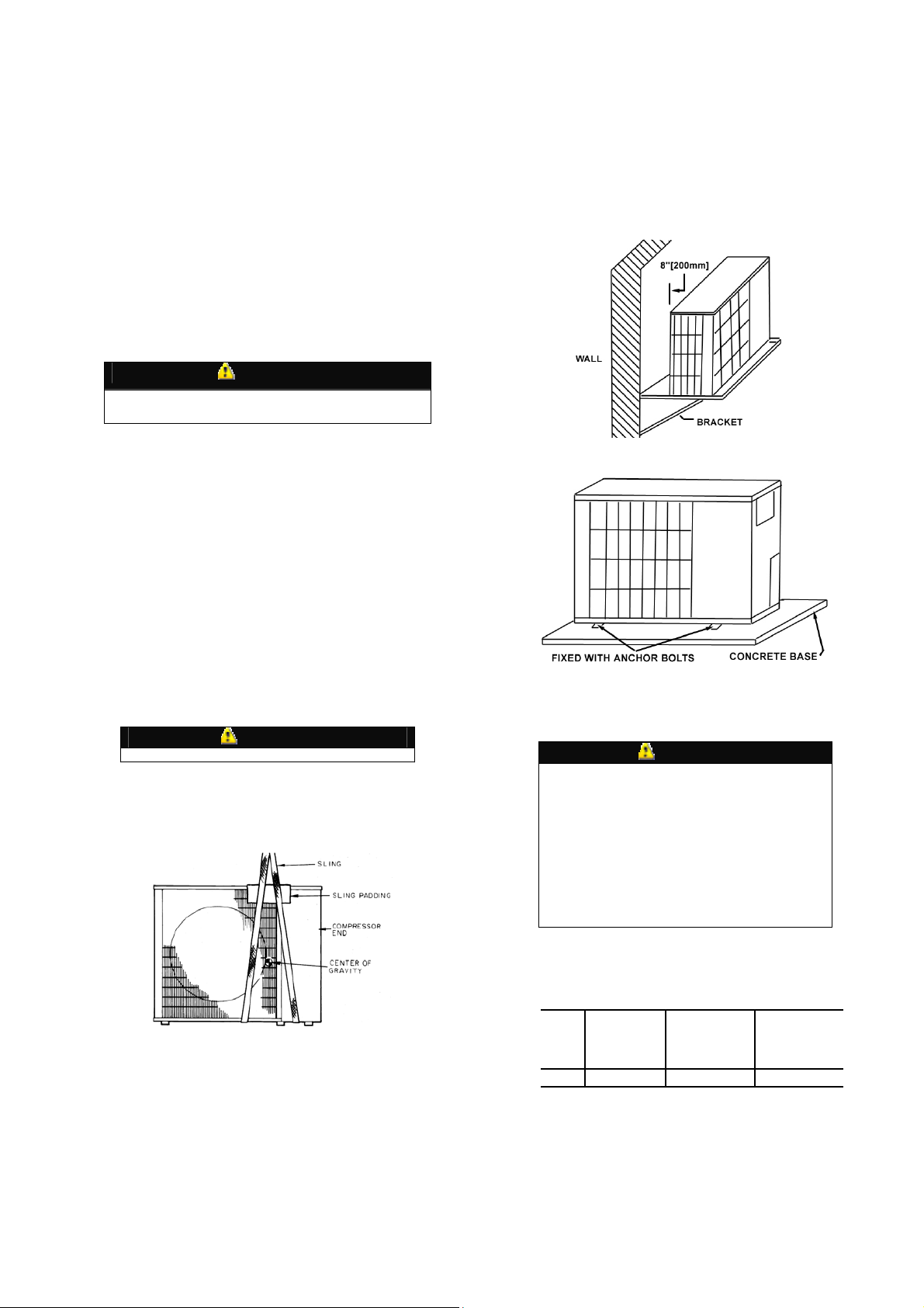
MOUNTING ON GROUND—Mount unit on a
solid, level concrete pad. Position unit so water
from roof does not fall directly into unit.
Accessory stacking kits can be used when units
are to be stacked. If conditions or local codes
require unit to be fastened to a pad, 6 fieldsupplied tiedown bolts should be used and
fastened through slots provided in unit mounting
feet. See Fig. 5 .
around the unit for air flow clearance, wiring,
refrigerant piping and servicing. The unit should
not be installed near to any source of heat, steam
or any flammable gas.
Step 3—Complete Refrigerant Piping
Connections
Outdoor units may be connected to indoor
—
units using field-supplied tubing of refrigerant
Fig.-4 Wall Mounting
MOUNTING ON WALL—See Fig. 4 for wall
mounting.
MOUNTING ON ROOF—Mount unit on level
platform or frame at least 6 in. above roof
surface. Isolate unit and tubing from structure.
RIGGING
CAUTION
All panels must be in place when rigging.
Keep unit upright. Lift unit using sling. Use
cardboard or padding under sling, and spreader
bars to prevent sling damage to unit. See Fig. 3.
Install unit so coil does not face into prevailing
winds.
Fig.-3 lifting unit with sling
MOUNTING POSITION— The unit should be
installed outdoors in a place where air will not
be stagnant. In case of installing more than one
unit, units should be arranged in a way that no
exhausted air will be sucked in as an intake for
another unit. Enough space should be kept
Fig.-5 Ground Mounting
grade and condition. Do not use less than 10 ft
of interconnecting tubing.
CAUTION
DO NOT BURY MORE THAN 36 IN. OF
REFRIGERANT PIPE IN THE GROUND. If
any section of pipe is buried, there must be a 6
in. vertical rise to the valve connections on the
outdoor unit. If more than the recommended
length is buried, refrigerant may migrate to the
cooler, buried section during extended periods
of system shutdown. This causes refrigerant
slugging and could damage compressor at startup.
When more than 50 ft of interconnecting tubing
and more than 30 ft of vertical lift is used, refer
to appendix in page 15.
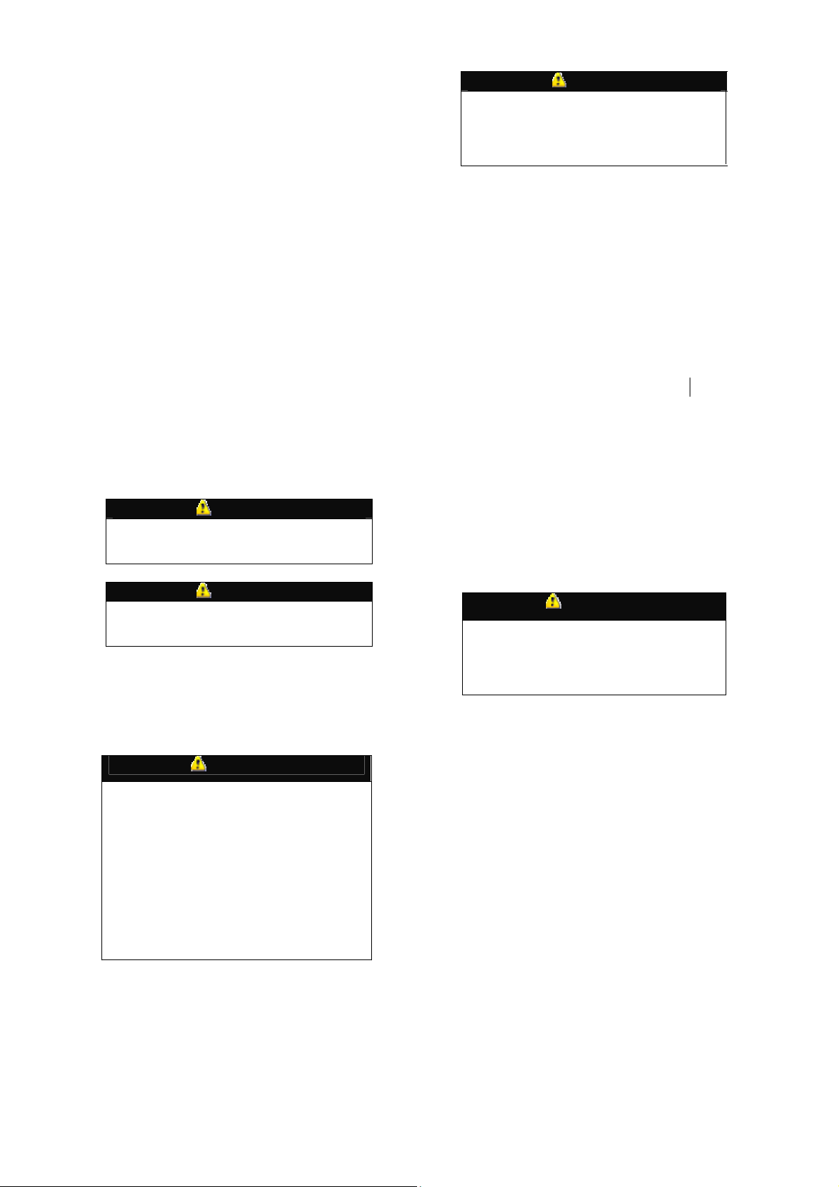
Table 1-MAXIMUM LINE LENGTHS
UNIT
38HK
*Maximum distance permitted is 30 ft from lowest
system component to highest system component.
MAXIMUM
EQUIVALENT
FT
50 30* 30*
If either refrigerant tubing or indoor coil is
exposed to atmospheric conditions for longer
than 5 minutes, it must be evacuated to 1000
MAXIMUM LIFT
— FAN COIL
BELOW
CONDENSING
UNIT
MAXIMUM LIFT
— FAN COIL
ABOVE
CONDENSING
UNIT
4
microns to eliminate contamination and
moisture in the system.
Run refrigerant tubes as directly as possible,
avoiding unnecessary turns and bends. Suspend
refrigerant tubes so they do not damage
insulation on vapor tube and do not transmit
vibration to the structure. Also, when passing
refrigerant tubes through the wall, seal opening
so that vibration is not transmitted to structure.
Leave some slack in refrigerant tubes between
structure and outdoor unit to absorb vibration.
Refer to separate indoor unit installation
instructions for additional information.
MAKE PIPING SWEAT CONNECTIONS—
Remove plastic caps from liquid and suction
service valves. Use refrigerant grade tubing.
Service valves are closed from the factory and
ready for brazing. After wrapping the service
valve with a wet cloth, the tubing set can be
brazed to the service valve using either silver
bearing or non-silver bearing brazing material.
Consult local code requirements. Refrigerant
tubing and indoor coil are ready for leak testing.
NOTE: Unit is shipped with R-22 Holding
factory charge indicated on nameplate. Pass
nitrogen or other inert gas through piping while
brazing to prevent formation of copper oxide.
CAUTION
To avoid damage while brazing, service valves
should be wrapped in a heat-sinking material
such as a wet cloth.
CAUTION
When brazing tubing sets to the service valves, a
brazing shield must be used to prevent damage
to the painted unit surface.
PROVIDE SAFETY RELIEF—A fusible plug
is located in unit suction line; do not cap this
plug. If local code requires additional safety
devices, install as directed.
Step 4 — Make Electrical
Connections
WARNING
Unit cabinet must have an uninterrupted,
unbroken electrical ground to minimize the
possibility of personal injury if an electrical fault
should occur. This ground may consist of
electrical wire connected to the unit ground lug
in control compartment, or conduit approved for
electrical ground when installed in accordance
with NEC, ANSI/NFPA (American National
Standards Institute/National Fire Protection
Association) 70, and local electrical codes.
Failure to follow this warning could result in the
installer being liable for personal injury to others.
CAUTION
Unit failure as a result of operation on improper
line voltage or excessive phase imbalance
constitutes abuse and may cause damage to
electrical components. Such operation will
invalidate any applicable Carrier warranty.
POWER WIRING—Unit is factory-wired for
voltage shown on nameplate. Provide adequate,
fused disconnect switch within sight of unit,
readily accessible but out of reach of children.
Provision for locking the switch open (off) is
advisable to prevent power from being turned on
while unit is being serviced. Disconnect switch,
fuses, and field wiring must be in compliance
with NEC and applicable local codes. Use
minimum 60 C wire for field power connection.
Route power wires through opening in the unit
side panel and connect in unit control box. Unit
must be grounded.
CONTROL CIRCUIT WIRING — See
Electrical Data Table and unit label diagram for
field-supplied wiring details. Route control wire
through opening in the unit side panel to
connection in unit control box.
NOTE: Use no. 10 AWG (American Wire Gage)
insulated wire
NOTE: Operation of unit on improper line
voltage constitutes abuse and could affect
Carrier warranty. See Table7.
Do not install unit in system where voltage may
fluctuate above or below permissible limits.
See Table 7 for recommended fuse sizes. When
making electrical connections, provide clearance
at unit for refrigerant piping connections.
WARNING
Before performing service or maintenance, be
sure the indoor unit main power switch is off
and indoor blower has completely stopped.
Failure to do so may result in electrical shock or
injury from rotating fan blades.
CONNECTIONS TO DUCT-FREE FAN COIL
UNITS —
The 38HD units are designed for easy match-up
to FB4A Fan Coil, 42TX Fan Coil,40GKX
Cealling Cassette and 42S/HD Free Standing fan
coils. See wiring diagrams page 9 – 11.
5
START-UP
Preliminary Checks
1. Check that all internal wiring connections are
tight and that barriers, covers, and panels are in
place.
2. Make certain field electrical power source
agrees with unit nameplate rating.
3. Open all service valves.
Leak Test— Field piping and fan coil must
be leak tested by pressure method described in
Carrier Standard Service Techniques Manual,
Chapter 1, Section 1-6. Use R-22 at
approximately 25 psig backed up with an inert
gas to a total pressure not to exceed 245 psig.
Evacuate and Dehydrate— Field piping
and fan coil must be evacuated and dehydrated
by either of the methods described in Carrier
Standard Service Techniques Manual, Chapter
1, Section 1-7.
Charge System — Release factory charge
into system by opening (backseating) liquid and
suction line service valves. Add charge amount
as required for the total system.
Refer to separate indoor unit installation
instructions for the required total system charge
when connected to the indoor unit.
PERCENTAGE DECREES IN CAPACITY DUE TO
MAXIMUM LINE LENGTHS
UNIT
38HK 50 30* 30*
*Maximum distance permitted is 30 ft from lowest
system component to highest system component. For
longer line application please refer to appendix A.
MAXIMUM
EQUIVALENT
FT
MAXIMUM LIFT
— FAN COIL
BELOW
CONDENSING
UNIT
MAXIMUM LIFT
— FAN COIL
ABOVE
CONDENSING
To Start Unit
NOTE: When using in conjunction with FB4A
Fan Coil, 42TX Fan Coil,40GKX Ceiling
Cassette and 42S/HD Free Standing fan coils.,
refer to start-up instructions included with fan
coil for correct start-up procedures. Be sure that
field disconnect is closed. Set room thermostat
below ambient temperature. Operate unit for 15
minutes, then check system refrigerant charge.
Unit compressor starts after a 5-minute delay if
equipped with accessory Time Guardt II device.
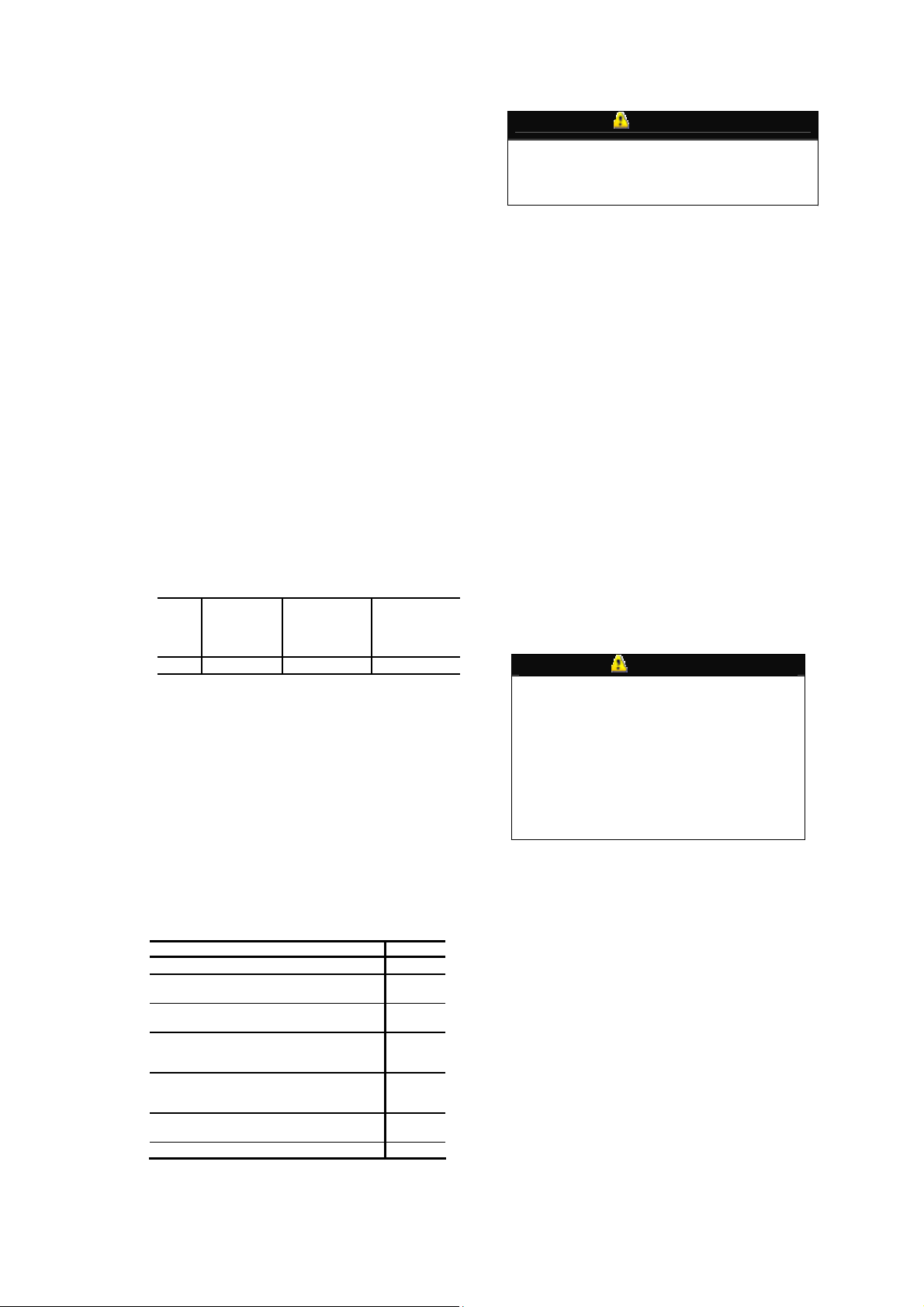
Table 6 - SYSTEM OPERATING CONDITIONS
TEMPERATURE CONDITIONS LIMITS
Maximum Cooling Ambient (F)
Minimum Cooling Ambient (F) (without
accessory low-ambient kit)
Minimum Cooling ambient (F) (with
accessory low-ambient kit)
Saturated Suction Temperature Range
Minimum (F) / Maximum (F)
Saturated Condensing Temperature
Range Minimum (F) / Maximum (F)
Maximum Compressor Discharge
Temperature (F)
Minimum Discharge Superheat (F)
NOTE: For system controls see Electrical Data.
20 / 55
60 / 150
6
UNIT
125
55
35
275
60
SERVICE
WARNING
Before performing recommended maintenance, be
sure unit main power switch is off. Failure to do so
may result in electrical shock or injury from
rotating fan blade.
Outdoor Fan— A reinforced wire mount
holds the outdoor fan assembly in place.
Compressor Pressure Relief Valve —
Valve is located in compressor. Relief valve
opens at a pressure differential of approximately
450 ± 50 psig between suction (low side) and
discharge (high side) to allow pressure
equalization.
Internal Current and Temperature
Sensitive Overload—
automatically when internal compressor motor
temperature drops to a safe level (overloads may
require up to 45 minutes to reset). When an
internal overload is suspected of being open,
check by using an ohmmeter or continuity tester.
If necessary, refer to Carrier Standard Systems
Techniques Manual, Chapter 2, for complete
information.
Control resets
Pumpdown Procedure— The system
may be pumped down in order to make repairs
on low side without losing complete refrigerant
charge. To pumpdown:
1. Attach pressure gage to suction service valve
gage port.
2. Frontseat the liquid line valve.
CAUTION
The 38HDL unit coils hold only the factorydesignated amount of refrigerant. Additional
refrigerant may cause units to relieve pressure
through compressor internal pressure relief
valve (indicated by sudden rise of suction
pressure) before suction pressure reaches 5 psig.
If this occurs, shut off unit immediately, then
frontseat the suction valve and remove and
recover excess refrigerant following accepted
practice.
3. Start unit and run until suction pressure
reaches 5 psig.
4. Shut unit off and frontseat suction valve.
5. Depressurize low side of unit and recover
refrigerant following accepted practice.
Loss of Charge Pressure Switch —
This switch, mounted on the suction line, has
fixed non-adjustable settings. To check pressure
switch, attach pressure gage to suction service
valve gage port. Slowly close liquid shutoff
valve and allow compressor to pump down. Do
not allow compressor to pump down below 2
psig. Compressor should shut down when
suction pressure drops to cutout pressure in
Table 2, and should restart when pressure builds
up to cut-in pressure shown in Table 2.
High Pressure Switch —This switch,
mounted on the discharge line, has fixed nonadjustable settings & auto reset. To check
pressure switch, attach pressure gauge to
compressor discharge service port, block
condenser coil, monitor pressure till compressor
trips, remove blockage and observe at which
pressure compressor restarts.
CAUTION
If the compressor does not trip at the cut-out
pressure (450 psig), remove the blockage
immediately and contact your local Carrier
service center.
Service Valves —The service valves in the
outdoor unit come from the factory frontseated.
This means the refrigerant charge is isolated
from the line-set connection ports. To prevent
damage to the valve, use a wet cloth or other
acceptable heat sink material on the valve before
brazing. The service valves must be backseated
(turned counterclockwise until seated) before the
service port caps can be removed and the hoses
of the gage manifold connected. In this position,
refrigerant has access from the through outdoor
and indoor unit. The service valve cannot be
field repaired; only a complete valve or valve
stem seal and service port caps are available for
replacement.
MAINTENANCE
WARNING
Before performing recommended maintenance,
be sureunit main power is off. Failure to do so
may result inelectrical shock or injury from
rotating fan blades.
Lubrication
COMPRESSOR—Compressor contains factory
oil charges; replace oil when lost. See Table 1
for oil recharge and refer to Carrier Standard
Service Techniques Manual, Chapter 1, pages 1
to 21 for oil recharging procedure.
Cleaning Coils — Coil should be washed
out with water or blown out with compressed
air. Note that the blowthru design causes dirt
and debris to build up on the inside of the coils.
Clean coil annually or as required by location
and outdoor air conditions. Inspect coil monthly
and clean as required. Fins are NOT continuous
through coil sections. Dirt and debris may pass
through the first section, become trapped
between the rows of fins, and restrict condenser
airflow. Use a flashlight to determine if dirt or
debris has collected between coil sections. Clean
coil as follows:
1. Turn off unit power.
2. Use a garden hose or other suitable equipment
to flush coil from the outside to remove dirt. Be
sure to flush all dirt and debris from drain holes
in the base of unit. Fan motors are waterproof.
WARNING
Do not use harsh chemicals to clean the coils,
use only water, compressed air or Carrier
approved coil cleaners.
7
 Loading...