

Page 1
Number One
Air Conditioning
l\Mer
e
Division of Carrier Corporatio
Syracuse, New York
Packaged Direct-Expansion Air Handler
Air-Cooled Condensing Unit System
GENERAL
This publication contains application infor
mation for Carrier 38AD, AE, BA, and GR con
densing units used in split systems with 40RR
direct-expansion air handling units, including
system selection, performance data, combination
ratings, electrical and control data, and refrigerant
piping details.
■ SELECTION PROCEDURE (With Example)
I Given:
COOLING
Grand Total Load (Req’d TC) . . 600,000 Btuh
Sensible Load (Req’d SHC) . . . 430,000 Btuh
Temperature Air Entering
Condenser
...............................................
95 F
Temperature Air Entering
Evaporator — edb...............................77 F db
Temperature Air Entering
Evaporator — ewb
Evaporator Air Quantity
External Static Pressure
..........................
..................
..................
64 F wb
20,000 cfm
1.12 in. wg
Length of Interconnecting
Refrigerant Piping (Estimate)
.................
90 ft
Electrical Power Source,
Volts/Phase/Hertz
............................
460/3/60
HEATING
Heating Load............................... 900,000 Btuh
Temperature Air Entering
Coil (edb)
Steam Pressure
................................................
......................................
58 F
5 psig
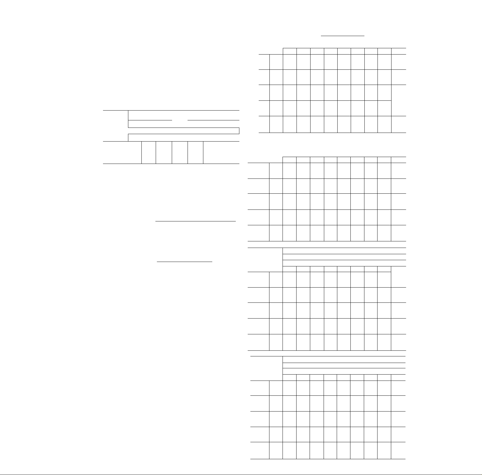
II Select condensing unit/fan coil combination.
Enter the Systems Index at the desired cfm
(20,000). Select the condensing unit(s) and
fan-coil system that meets or exceeds the grand
total load (600,000 Btuh). In this example,
system no. 48 would be selected — two 38AD
024 and one 38AD016 condensing units and a
40RR054 fan-coil, yielding a nominal capacity
of 632,000 Btuh. To determine whether this
system will fully satisfy the cooling require
ments, enter the combination ratings, system
no. 48, page 9, at 20,000 cfm and 95 F condenser
entering air temperature. By interpolation, at
SYSTEMS INDEX
CONDENSING
_UNIT(S)
GR006
ВА008
¡38
ВД009
ВА008
38
ВА009
AD012
AD012
AD014
38
AD016
AD012
AD014
338
AD016
AD024
ADO^g-
AD012 (2)
38
AD024
AD028
AD024
AD012 (2)
AD028
38
AD016 & AD012
AD034
AD016 (2)_
ADÔ28
.............................
AD016 & AD012
AD034
38
AD016 (2)
AD024 & AD016
АЕ044
‘XÿJX'SVK
ш
в
шш
т
ШФ
Шщ
EER — Energy Efficiency Ratio
ТС — Total Capacity (1000 Btuh)
*ARI capacities, Energy Efficiency Ratios rated in accordance with
tFor units operating at 208 v, deduct 1000 Btuh from capacity
AD034
AD012 (3)
AD016 & AD024
AD016 & AD012 (2;
АЕ044
38
AD016 (2) & AD012
AD016 & AD028
AD016 & AD034
AD016 (3)
АЕ054
АЕ044
AD016 (2) & AD012
AD016 & AD034
AD016 (3)
AD024 & AD034
АЕ054
AD024 (2) & AD012
AD024 (2) & AD016
АЕ064
latest ARI Standard 210
rating
___
__
FAN
COIL
В А 009
RR 008
RR012
RR016
R R 024
RR026
R R 034
R R 044
R R 054
NOM
CFM
40
3.400
3.400
2,360*
40
3.000
3.000
j^OOO
4,5ÔÔ~
40
4.000
4.000
4/950*
6.000
40
6,000
6,000
40
8,000
40
10,000
40
12,000
40
16,000
40
20,000
ARI OR
NOM TC
'""'бЗ*''"
Î2Ô*t”^
"48I
88
100_
87
98
110
144
157
166
181
216
196
238
238
279
252
300
300
325
335
312
313
342
359
393
422
378
392
429
434
451
479
502
498
510
524
512
537
557
579
567
590
632
638
EER*
-
Tir
6 T'
9 0
7 6
7 6”'
9 5
8 2
8 6
© Carrier Corporation 1975
Form 38AD-5XA
Page 2

64 F evaporator entering air wb temperature,
the system has a total capacity (TC) of 600,800
Btuh, and a calculated sensible heat capacity
(SHC) of 498,800 Btuh. For close-coupled
systems (15 ft or less of interconnecting pipe),
an additional 2% may be added to both TC and
SHC. As this system is not close-coupled, the
ratings are used directly from the combination
ratings. At this point, the sensible heat capacity
is adjusted for the evaporator entering air db
temperature. For 20,000 cfm, the bypass factor
is 0.18. The adjusted sensible heat capacity is:
Adj SHC = SHC + [1.09 X cfm x (1—bf)
X (edb-80)]
= 498,800 + [1.09 X 20,000
X (1-.18) X (77-80)]
= 498,800- 53,600
= 445,200 Btuh
Therefore, the selected system will meet all
cooling requirements.
Find heating capacity of selected fan-coil unit.
Enter Table 3, page 10, for 40RR054 and
20,000 cfm. A one-row nonfreeze steam coil
will deliver 915,000 Btuh based on 60 F enter
ing air temp, and 2 psig steam. To find the
corrected heating capacity, enter Table 1, page
10, for steam coils at 5 psig steam and 58 F
entering air temperature. By interpolation, the
correction factor is 1.062.
Corrected capacity =
915,000 X 1.062
971,700 Btuh
Leaving air db
edb -t-
58 +
corrected capacity
1.09 X cfm
97\_J00
1.09 X 20,000
= 102.6 F
The heating coil has sufficient capacity and the
leaving air db is less than the maximum
temperature of 140 F.
IV Determine fan rpm and bhp.
Refer to Table 14, page 17, for a 40RR054 at
20,000 cfm and 1.12 in. wg external static
pressure, plus 0.07 in. wg for the heating coil
(Table 4), indicates a fan rpm of 828 and
requires 12.6 bhp. As this rating point is within
the shaded area, the fan drive must be selected
and purchased locally.
V Determine size of liquid and suction lines.
Table 11, page 14, indicates the pipe sizes for
the various condensing units. These sizes are
based on an equivalent length equal to the
maximum length indicated plus 50% for fit
tings. A more accurate estimate may result in
smaller pipe sizes. Enter the table with the
condensing unit (38AD024) and the estimated
length of interconnecting pipe (90 ft). The
suction line will be 2 1/8-in. OD and the liquid
line is 7/8-in. OD. Similarly, for the 38AD016,
the suction line is 2 1/8-in. OD and the liquid
line is 7/8-in. OD. If a 38AD034 — 38AE054
condensing unit is used with more than 25 ft of
piping, a double suction riser may be required.
VI Find size nozzle, TXV and solenoid valve.
To determine the nozzle(s), TXV(s), and sole
noid valve(s), enter Table 6, page 13, with the
system number. Tables 7, 8, 9, and 10 give the
part numbers for the keys indicated in the
previous table. For this example, a C12 nozzle
would be used in each of the 3 distributors.
Also, the TXV’s and solenoid valves used would
be (using Carrier Part No.):
FAN
COIL
40RR054
COND
UNIT
38AD024
38AD024
38AD016
COIL
SECT
u
M
L
TXV
EA03PC503
SOLENOID
VALVE
EF11BS28
EE11BS28
None Requ ired
Part numbers for Alco and Sporlan valves are
obtained in a similar fashion. Also, for several
systems, a single solenoid valve will control
both the middle and lower coil sections as
exemplified by system no. 49. These systems
should be piped in accordance with Fig. 5, page
16. When the condensing unit is below the
fan-coil unit, the maximum liquid lift as pre
sented in Table 13, page 15, should be adhered
to.
Page 3
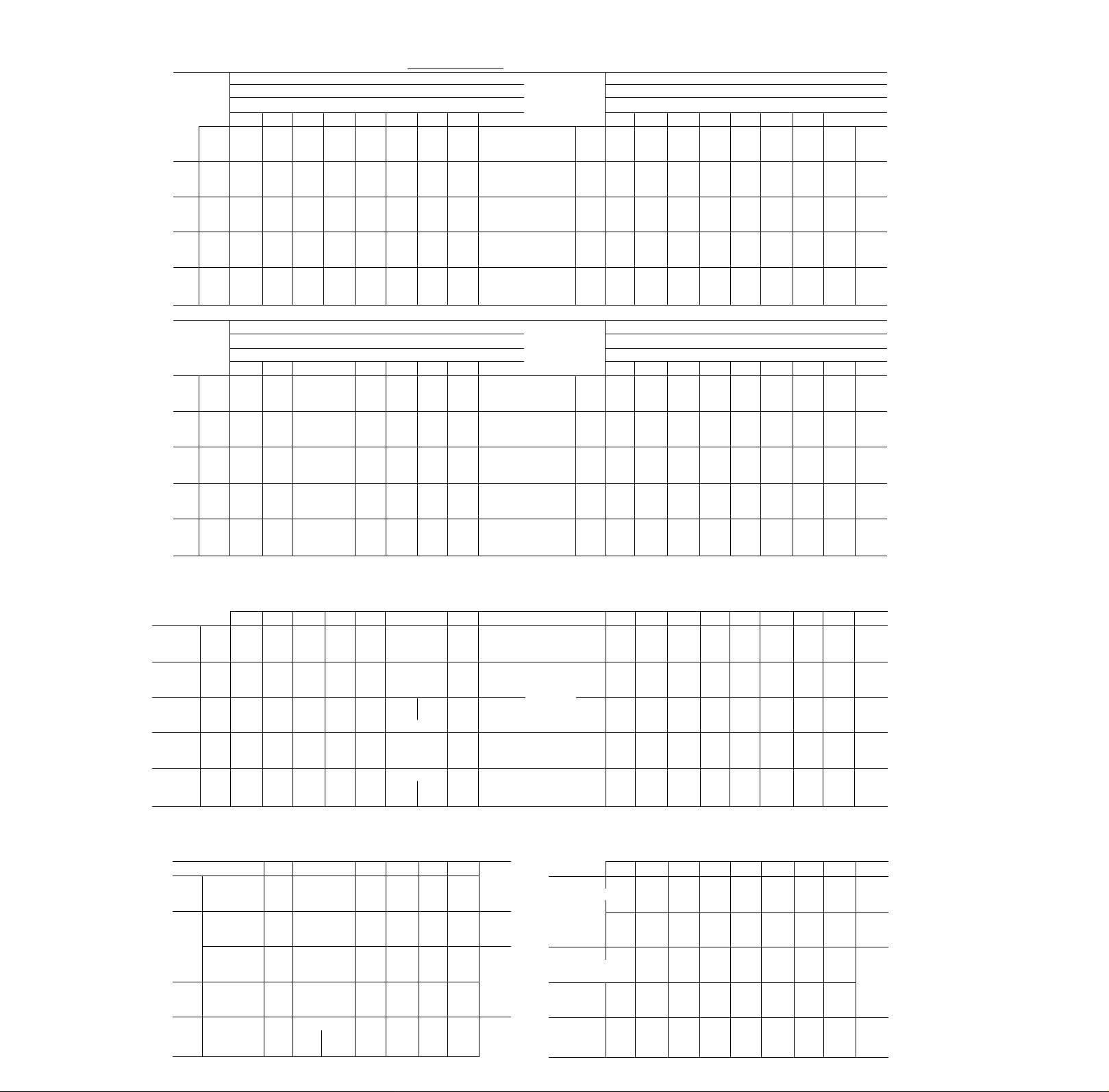
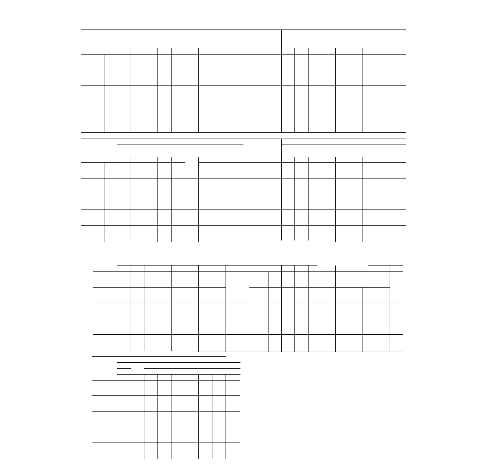
COMBINATION RATINGS
Ratings Notes
1. Direct interpolation is permissible. Do not
extrapolate.
2. SHC is based on 80 F db temperature of air
entering evaporator coil.
Below 80 F db, subtract (corr factor x cfm)
from SFIC.
Above 80 F db, add (corr. factor x drn) to SHC.
ENTERING AIR DRY
BYPASS
FACTOR
.10 97
.20
.30
...
Interpolation is permissible
Correction Factor = 1 08 x (1
79
81
86
76
78
1.95 2 92
1 73 2.59
1 51
77
Correction Factor
2.27
-BULB TEMP (F)
— r
76^
75 1 under 75
85
3 89
4.86
3 46 4 32
3 03
3 78
BF) X (db - 80)
ovec/85
use formula
shown be low
3. Gross capacities shown do not include a deduc
tion for evaporator fan motor heat.
4. Formulas:
hdb “ tedb
sensible heat capacity (Btuh)
1.08 X cfm
tiwb “ wet-bulb temperature corresponding to
enthalpy of air leaving evaporator coil
(hlwb)
hlwb - hewb
total capacity (Btuh)
4.5 X cfm
where hewb ~ enthalpy of air entering evap coil
5. Combination ratings are based on a 2 F line
loss. For a close-coupled system (less than
15 ft), add 2% to ratings. Piping sizes in Table
13 are based on 2 F line loss. All combination
ratings are based on R-22.
LEGEND
BF — Bypass Factor
TC — Total Capacity (1000 Btuh)
SHC — Sensible Fleating Capacity (1000 Btuh)
KW >- Compressor Motor Power Input
Ewb — Entering Wet-Bulb
U - Upper Coil
M — Middle Coil
L — Lower Coil
U-M-L abbreviations indicate connection of condensing unit to upper.
middle or lower coil of fan-coil unit
i 38GR006 and 40BA009
T emp(F)
Air Ent
TC
85 SHC
KW
TC
95 SHC
KW
TC
100 SHC
KW
TC
105 SHC
KW
TC
SHC
115
KW
2875/. 13
72
67
81
74
46 60
8.2
7.7
75
69
44
57
8.7
8.2 7.9
72 66
43 58
8.9
8.4
69
64 61
42 56 61 49
9.2 8.7 8.4
59
63
40
53 57
9 6
9.1
38BA008 and 40BA009
Temp(F)
Air Ent
TC
85 SHC
KW
TC
SHC
95
KW
TC
SHC
100
KW
TC
SHC
105
KW
TC
SHC
115
KW
2500/. 16
72
67
101
93 85 105
50
62 74 55
7.7
7.4 7.0
96 89
48 60
8.4
8.0
94 86
48 59 71
8.7
8.4
91
84
47
58 70
9.1 8.7
86 79
45
57 68 50
9.8 9.4
^^38BA009 and 40BA009
Air
Ci
85
95 SHC
100
105
115
Ent
TC
SHC
KW
TC
KW
TC
SHC
KW
TC
SHC
KW
TC
SHC
KW
2500/. 16
72 67
112
103
54
67 79 59
9.9
10.5
108 99 90
53
65 77 58
11.2 10.7
105
96 89 no 101
52 64 76
1 1.6
11.1 10.5 12.0
102 94 86
51
63 75
12.0
11.4 10.8 12.5
96 89 81 101
49
61
12 8 12 2 1 1 6
38GR006 and 40RR008
2525/. 19 3375/.23 42257.26
r.
85
95
100
105
115
72
TC
SHC
KW
TC
SHC
KW
TC
SHC
KW
TC
SHC
KW
TC
SHC
KW
67 62 72 67 62
79 71 65 81 74
55
43
7.7 7,2 6.9 7.9
73 67 62 75
41 54
8.2 7.7 7.4 8.1
71 64 60 73
40 53 60 47
8.4 8.0 7.6 8.6 8.2 7,9
62 58
68
39
52
8.7 8.2
58 55 65 60
63
50
38
9.1
8.6
Evgp Air - Cfm/BF
3825/. 16
Evap Air - Ewb (F)
62
72
67
69
83 77 74 84
69
53 70 74
7.4
8.3 7.9
65
77
65
51
8.9
63 74
63 50 65
8.2 9.1
71
9.4
57
64 60 60
47 60 60
8.9 9.8
62 72 67
7.7 8.4 8.0
71 69
67 69
8.4 8.3 9.0 8 5
68 67 74
67 56
8.6 8.5
66 65 71
64
8.9 8.8 9.5 9.0
9.3
9.2 8.8
65 55
65
9.3 9.9 9.5
ARI - 88,000 Btuh
Evap Air - Cfm/BF
3400/.23
Evap Air - Ewb (F)
62 72
81 100
72
7.6 8.5 8.2 7.8 8.6
79 98 89
7.9 8.9
77 95
8.2 9,3 8.9 8.4
73 90 82 75 91
9.0 9.9 9.5 9.1 10 1
Evap A
67 62 72
97 89
70
7.8 7.6
92 85 102 94
53 68 84
52 68
8.5 8,1 8.9
87 80 97 89
52 67 80 55
65 75
108 99 91
86 59 70
7.2 7.9
83 100 91
81 56 74
AR
- 100,000 Btuh
ir - Cfm/BF
57 75 87
9.4
53
3400/.23
E vap Air - E
62
72 67 62 72
94
118 108 99
9.5 10.7
113
10.2
11.6
57 72 87 61 79 95
106 98
56
72 54
13 2 12 5 11 9 13 4 12 7 12 1
wb (F)
75 90 64 82 101
10.2 9.7 11,1 10.5 9.9
104
73 88 62
11,0 10,5 11.9
1 1.4 10,8
71
11.8
92 83 103
69
121 112 102
95 1 16 107
93 113 104 95
12.3
90
109
60
86
11.0 12.7
83 58
E vap Air — Cfm/BF
E vap A ir — Ewb (F)
72
70
83
65 50 64
62 48
70
58 46 60 62
7.9
8.9
55 44 57 58
8.3 9.3 8.8 8.7
70 56
7,4
69
62 66 53
7.9 7.7 8.5 8.1
67 64 74 68 67
61 64 52
64 62
8.4
8.0
7.2
66
8.7
9,0 8.5 8,4
8.2
58
9 4 8.9
76 71 69
71 66 65
51 65 65
65
49 61
4775/. 19
62
78 77
59 76
78
57
53 62 62
7.9
72
72
8.5
69
69
8.8
67
67
9.0
62
9.6
4300/.28
67
62
91
7.6
7.3
87
8,2 7.9
85
84
8.6 8,2
82
73 82
9.0
8.5
84 77
71 77
9.7 9.3
4300/.28
67 62
98
80
98
11,3 10.6
10,9
11.7
101
92
78 92
12.1 1 1.3
95 87
76 87
67 62
76 74
74
72
7.6 7.4
69 69
7.9
67 67
8.2
8.3
61 61
61
8 9
77
72
72
70
70
67
67
62
Page 4
:^^38BA008 and 40RR008
2200/. 17
72 67 62 72
Tc
85
95
100
105
115 SHC
96 88 81 100
SHC 46 57 67
KW
7.5 7.2 6.9
TC
91 84
SHC
45 55 66 50
KW
8.2 7.7 7.4
TC
89
SHC
44 54 65
KW
8.4
TC
87
SHC
43 54 64
KW
8.9 8.4
TC
82
41 52
KW
9 6 9.1 8.7 9 8
¡38BA009 and 40RR008
2200/. 17
72 67 62 72
TC
85
95 SHC
100
105 SHC
115
105 97 89
SHC
50
KW
10.1 9.6 9.1
TC
101
48 59
KW
10.8 10.4 9.9
TC
99 91
SHC
48
KW
TC
KW
TC
SHC
KW
10.7
11.2
96 89 81 101
47 57
11.7 11.0 10.5 12.0
92
45 55
12.4 11.8 11.1
38AD012 and 40RR008
Temp(F)
Air Ent
2200/. 16 3000/.20 3800/.23
72 67
TC
85 SHC
95
100 SHC
105
115 SHC
119 107 98 124
54
KW
11.4 10.8 10.3
TC
113 103
SHC
52
KW
12.2 1 1.6
TC
1 10
52
KW
TC
SHC
KW
TC
KW
11.9
12.6
108 99
51 62 73 56
13.1 12.4
103
49 60
13 8 13 2 12 4
38AD012 and 40RR012
Temp(F)
Air Ent I
v.o na f"— -
TC il 33 122 112
SHC i 64
85
KW hi.4
TC i! 125
95
SHC j 61
3000/. 16 4000/.20
1 72
10.8
KW il2.4 11.6 10.9 il2.7 12.0
tc j 122
100
SHC 60
105
115
KW ! 12.8
TC i 118 ^
SHC 58
KW j 13.2
Tc“l n 1
SHCj 56
KW 114 0
12.0
12.4
13 1
E
vap Air - Cfm/BF
3000/.21
Evap Air — Ewb (F)
67
62
92
51
7.6
77 96
82
8.1 7.7 8.7
80
76 79
8.4
76
93
49
74 91
48
8.0 9.0
86 79
46
62
Evap A
85 104
65
79
7.4 7.0
88
81
64
77
8.0
7.6 8.4
86 79
77
63
7.9
8.2
84 77
62 76
8.5
8.2 9.2 8.8
72
60
72 51 67
9 4 8.9 10.0
ir - Cfm/BF
3000/.21
Evap A
if — Ewb (F)
67 62
61 71 55
93 85 107
58
84 77
111
10.3
69
54
11.1
104
83
68 53 67 80
11.5 1 1.0
10.2
68
52 66 79 57 74
96
66 50
12.9
94
102
69
83
9.9
9.4 10.6
98 90 no
68 81 58 75
10.7
10.2
95 88
10.5 11.8 1 1.3 10.7
86 105 96 89
93
11.2
10.8 12.3
88 81
77
64
12.1 11.5
Evap Air — Cfm/BF
Evap Air - Ewb (F)
62 72
76 60
66
64 75 58
101 92 116
63
94
11.9
94 119
10.9 12.7
74
57
13.1
11.2
90
113 104 96
11.7
13.5 12.8
108
86
70
54 69 82 60
14 2
62 72 67
67
114 105 128
75 88 65 82 101 85
11.2 10.7 ¡12.0 11.5
101
1 10
87
73
1 1.4
12.0
107 98 1 19
72 86 62
12.3 1 1.7 13.4
71 85 j 62
12.2 •il3.7
99 91 111 103
13 6 12 8
Evap Air — Cfm/BF
Evap Air — Ewb (F)
62
67
79
116 106 i 131 121 1 12
76
113 103
75
109
74 88
102 94
71
1 72 67 62
139
94
10.2
91 68 86 105 74 96
90 i 67 85 104 73
11.2
100 1123
11.6 113.6
86
12 3
129 118 143
89 108 77
jll.8 11.2 10.5
11.3
109
118
1 127
i 13.1 12.4
j 65
j 115 107
] 62 81
1143
11.6 13.3
105 128
1 14
84
102
12.0 13.8 13.0 12.3
12.8
98
98 68
13.6
12 6 14 7 13 8 13 0
COMBINATION RATINGS
ARI - 87,000 Btuh
3800/.24
72
67
62
95
56 73
7.7 7.4
98 91 84
54 71 84
95 89
53
8.8 8.4
93
53
88 81 75
ARI - 98,000 Btuh
3800/. 24
72 67
115
60 77
11.4
108
58
99 91
55
13.0 12.4
123
63
12.9 12.3 11.7
1 7
14 5
5000/. 23
72
12.0
135
12.9
132
71 93 108
118
88
88
7.2
8.1 7.7
81
70
82
8.1
86
79
69 79
8.4
75
9.6 9.1
11^ 38AD016 and 40RR012
62
106
98
93
10.0
9.6
102 93
92
10.8 10.4
99
91
74
91
89
11.7 11.0
84
71
84 115 SHC
11.7
62 72 67 62 72 67 62
118
109
11.0
114
105
81
98
111
102
79
98 100
12.6 12.0 KW
108 1 10 TC
79
96
13.1 12.5
94
77
93 115
13 9
13 1
67
62
/-¡22
132
99
121
1 1.4
10.8
125
115
115
11.4
12.2
121 112
95 112
11.8
12.6
117
108
109 101
90 101
38AD014 and 40RR012
3000/. 16 4000/.20 5000/. 23
72 67 62 72 67
tc
156 143 130 165 152
SHC
85
95
100 SHC
105 SHC
US SHC 71
-r.
T ( * 7
80 95
KW
15.7 15.0 14.2 16.3
TC
149 136 123 158 144
SHC
77 92 108
KW
16.8 15.8 15.2
TC
146 133
76 91 107 76 94
KW
17.1
TC
KW
TC
KW
16.6 15.6
141 129 117 149 136
74
16.7 15.9
17.5
134 122 Tl 1
18.5 18.0 16.7 19.2 18.2
3000/. 16
72 67 62 72 67
TC
166 153
SHC
85
95
100
105 SHC
78 93
KW
14.8 14.0
TC
161
SHC
KW
TC
SHC
KW
TC
KW
TC
KW
148
75 90 104
15.0 14.4
15.6
157 145
74
16.0 15.4 14.8 16.6 15.9
141
153
72 87 102 78 97 117 85
16.5 15.8 15.2 17.2
134
146
70 85 98 76 95
16.7 16.0 18.5 17.6
17.8
38AD012 and 40RR016
T emp(F)
Air Ent
95
105
.
»
TC
SHC
KW
TC
SHC
KW
TC
SHC
SHC
KW
TC
SHC
KW
4500/. 15 6000/. 19
150 139 128
79 101
12.5 1 1.9
142 131
76 98
12.7 12.1 13.8 13 0 12 3
13.3
127 117 142
137
75
13.7 13.1
132 122 113
73 94 113
14.2 13.5
123 113
69 91
14.9 14 2 13 4
38AD014 and 40RR016
Temp(F)
Air Ent
4500/. 15 6000/. 19
72 67 62
|tc
SSjSHC
95 SHC
I KW
lOOlSHC
i KW
105* SHC
! KW
115 SHC
179 166 152 188
91 113 135 98
KW
17.1
ftc”
171
88 1 10
18.1
|TC
166
87 108 130 93 122 148
18.7
!TC
161
85 106
19.3
rtc~
153
8 : 102
KW
20 2 19 2
16.3
158 145
17.3
154 141 174 161
17.9 17.C 19.4
149
18.3 17.2
140
E vap Air - Cfm/BF
Evap Air - Ewb (F)
79 98
111
120 154 141
89 105
86 102 71 90
Evap A
15.4
77
17.3 16.4
17.9 17.1
74
18.3 17.2 16.4
141
129
Ir — Cfm/BF
4000/.20
Low
Suet
133
131
89 103
128
122
Evap A
-
ir - Ewb (F)
176
163 150
84 104
14.6
15.3
170
157 144 175 163
82 101 120 88 111
16.0
15.5
166
153 141 171
80
162 149
16.4
154
142
Evap Air -
Evap Air — Ewb (F)
157 145
89 117
123
12.7 12.2 1 1.5
11.2
120 147 135 125
120
85 113 125
117 84 112
96
12.4
12.7 14.6
105
105
130
13.4 12.6
14.2
136 126
110
82
13.8
126 117 108 128
79 101 108
15.2 14 5 13 7
Evap Air — Cfm/BF
Evap Air — Ewb (F)
72
67 62
174
127
15.5 17.6
16.7 15.9
180 166
132 95 123
16.4
18.7
17.8 16.9
18.3
137 168 156
128 91 121
19.9 18.9 17.7
_
_
-
148 134
115 134
19 7
128
124
18 2
62
138
118
14.7 16.7
131
96 114
15.6
128 160 146
1 12 81 104
15.8 18.2
125 154
93
1 11
118 145
108
17.1 19.9
62
122 91
13.9
14.8 16.2
99
119
15.2
137
15.6
130 159
1 13 82
16.5
133
133
121
121
1 16
1 16
13.0
160 191
155
153 182
152
148
17.4
143
143
18 7
72 67 62
171 158 144
85 108 131
164 150 137
83 106 127
17.6 16.7 16.0
80
18.8
77
15.0
15.8
134
126
17.3 16.4
130
142
102 124
17.7 16.7
122
134
100 121
18.5 17.6
5 000/. 23
72 67
181
15.4
87
16.8 16.1
166 155
17.4 16.6
18.8 18.1
62
154
168
114 136
14.9 14.1
150
134
15.0
15.6
159 146
110 133
15 4
142
108 131
15.9
147 136
104 127
17 0
7500/.22
72 67
160
100 133
12.8 12.3
149 137
96
13 8 13 2
144 133
95 128 123
14.2 13.5
138
93
14.7
89 118
15 4
62
147 136
136
11.7
127
127
129
12 4
123
13.0
118
128
126 118
13.6
13.9
110
118
no
14 6 13 9
7500/.22
72 67
107
17.8
105
18.9
178
104
19.4 18.8
—
_
-
_
_
-
62
165
178
145 165
17.0 16.2
170 157
157
139
18.0 17.2
164 152
152
138
17.7
158 146
135 146
18.1
19.2
137
148
137
131
19 0
20 0
Page 5
COMBINATION RATINGS
r38AD016 and 40RR016
P(F)
4500/. 15
E vap
E vap Air — 1
72 67 62 72 67
TC
199 182 168 206 191 176
SHC
85
95
100
105
115
0^38ADO24
94 117 139
KW
TC
SHC
KW 17.2 16.5 15.7
TC
SHC
KW
TC
SHC
KW
TC 166* 157 144
SHC
KW
15.4
16.1
189 174 160
114
91
184 170
90 112
17.8 17.0 16.2
180 166
88 110
18.4 17.5 16.7
84 106
19 4
18 8
and 40RR016
104 133 161
14.5
16 4 15.7
196
135 101 129
17.6
157
192 178
134 99
18.2
153 188
132 97
18.8 18.0
174* 160*
128 75 122
19 9 19.1
17.8
E vap A
A
Pr.*
4500/. 15
E vap A ir - E
72 67 62 72
TC
85 SHC
95 SHC
100
105
115
232 213 195 246 226
134 157
111
KW
19.9 18.8 17.9 20.5
TC
KW
TC
SHC
KW
TC
SHC
KW
TC
SHC
KW
204
222
107 130
20.1 19.0
21.6
199
218
105
128 150 115 144
22.2 20.8
194 177 224
213
103 126 148 113
22.8 21.5 20.3 23.5 22.3 21.1
185
203
99 122 144 109
23.0
24.4
121 151 180 131 166 201
186 235 216
117
152
22.0 20.9 19.8
182 230 21 1 193 238 219 200
19.6
22.7 21.6 20.4
168 213
25.1
21.7
38AD016 and 40RR024
T emp(F)
Air Ent
uona
TC
SHC
85
KW
TC
95 SHC
KW
TC
SHC
100
KW
TC
SHC
105
KW
TC
SHC
115
KW
6000/. 15 8000/.18 1 10,000/.2r
72 67 62 72 67 62 72 67 62
214 198 183 221 206
139 169 121 160 190
108
17,0
16.2
189
204
105 135 165 118 156 181
18.1 17.1
185 171 205 191 177
199
134
104
17.8
18.7
180
193
102 132 162 1 14 153
18,5 17.4 20.0
19.4
179* 166* 156 184* 171* 158* 188*
98 128 156 112
19.4
20.3
Evap Air — Cfm/BF
Evop Air — E\yb (F)
17.4
15.5
210 196
175
18,6 17.7 16.8 18.7
16.6
164 116 155 177 128 172 181
17.0
19.3
166 199
20 6 20 1
18 7
[38AD012 w/U, 38AD012 w/L. of 40RR024
Temp(F)
6000/. 15
E vap Air — Cfm/BF
vap Air — Ewb (F)
E
72 67 62 72 67 62
TC
85 SHC
95 SHC
100 SHC
105 SHC
115 SHC
257 237 217 269
126 156 186
KW
22.7 21.5 20.2 23.4 22.2
TC
246 226
122 1 52 181
KW
TC
KW
TC
KW
TC
KW
23.1
24,4
240
221 203
119 150 179
23.9
25.2
233 215 198 243 224
1 16 147 177 130 169 205 143
26.1 24.7
220
204 188 228 212 196 233
1 12
143 172
27.8 26. ;
139
257
208
135 174 212
21.7
25.1 23.8 22.5
250
133 172
22.4
26.0 24.6 23.2 26.5 25.2 23.8
23.1 26.9
125
24,5 28,7 26,9 25,3
A
ir — Cfm/BF
6000/. 19
7500/ 22
:wb (F)
62 72 67
211 197
1 13 147
15.1 16,8 15.9
181 168
16.7
128 156 108
17.3
174
126 154 106
200
187
109
158
16.2
164
16.7
159
17.2 19,2 18.3 17.5
149 177* 165*
146 103
18.3 20.3 19.3
143 173
17.9 17,0
196
183
141
18.5 17.6 16.9
192 178 164
139
137 154
ir - Cfm/BF
6000/. 19 7500/.22
Iwb (F)
67 62 72 67 62
254
207
18.6
19.5
198 243 224 205
147 175 127 162 196
173 125 159
206 188 232
171
142
195
178
138 166
23.8 22.5 25.6 24,3 23.0
190
15.9
16.5
181
17.4
18.4
185
172 203
172 126 171 176
18.0
18.8
149
158
18 8 21 ;
235 216
20,0 19.0
21.0
21.4
22.5
23.2 22.1
^213
157
123
24.0
22.8 21,6
220
202 185
119
153 185
226
21 1
178 195
133
16.9
17.5
215 200 186
129 173
17.9 17.0
209 195
18.4
19.6
189 176
19 1 18 2
20.5
175* 161*
167 161
122
20 1 19 0
8000/. 18 10,0007.21
72 67 62
249
178
238
231
25.4
164
277 256 ^236
228
216 152
21.0 23.7 22,6
218 264
213
209
207 249
24.G
196 138 184
199 236
244
147 193 225
25.7 24.4 23.2
257 237 220
145 191
230 214
188 214
26.0 24.5
27.4
216 201
29.2 27,5
38AD024 and 40RR024
P(F)
62
182
178
15.3
173
16.3
169
169 100 SHC
Cr
85
95
TC
SHC
KW
TC
SHC
KW 22.7
TC
KW
TC
164
154
18 7
105 SHC
KW
TC
115
SHC
KW
38AD028 and 40RRd'24
1 ciiiH VI
K
G
Slid
TC
SHC
85
KW
TC
95 SHC
20.3
KW
TC
105
115
SHC
KW
TC
SHC
KW
TC
SHC
KW
194 100
20.9
195
192
|^"38AD024 and dORRO^d”
Temp (F)
Air Ent
195
16.1
186
TC
85 SHC
KW
TC
SHC
95
KW
181
17.6
TC
100 SHC
KW
TC
105 SHC
KW
TC
115 SHC
KW
BF — Bypass Factor
TC — Total Capacity (1000 Btuh)
21.5
225
SHC — Sensible Heating Capacity (1000 Btuh)
KW — Compressor Motor Power Input
Ewb — Entering Wet-Bulb
U — Upper Coil
M — Middle Coil
220
L — Lower Coil
U-M-L abbreviations indicate connection of condensing unit to
upper, middle or lower coil of fan-coil unit
*Capacities at a minimum 38AD016 charge to prevent high
pressurestat cutout Other capacities are at optimum charge for
201
25.7
maximum capacity.
E
vap /
6000/. 15
72
67
259
238 218
128 159
21.2 20.1
247 227
124
241
121
23.4
235 216
1 19
24.2 23.0
223 205 187
115 145 175
25 9
189
19.1
208
154
185
21.5 20.4
222 203
152
182 134 174
21.0
22.2
197 246
150 180
21.7 24.9
24.5 23 2
6000/. 15
62
iir — Cfm/BF
8000/. 18
E
vap /
ur - Ewb(F)
72 67 62
271 250
142 181
21.8 20.7
258 238 218 265
137 176 215 150
23.3 22.1 21.0 23.7
252
24.5 22.8 21.7
133 172 207
233 214 196 239
129 167 196
26 5 25 2 23 8 26.9
E vap
A
229 279 257 237
220
19.7
132 213
211 147
226 207
22.4
23.6
ir — Cfm/BF
8000/. 18
10,0007.21
72 67 62
154
201
22.1
21.1
245 225
197
22.5
259
239 219
194 219
24.5
23.3 22.1
252
232 213
145
192 213
25,3 24.0
220 201
141 187 201
25.6 24 3
10,0007.21
20,1
2-n4
22.8
Evap Air — Ewb (F)
72
67
299
62 72 67 62
274
141
29.8 27,4 25.7
288 264
137
31.6
283 259
135
32.5 30,6 29.;
275
133 162 194 146
33.4
263 242 221 275
129
34 7
251 315 291 267
172 202
166 198
29.8
165 196
253 232
32.2 30,5 34.6 32.7
158 189
33 3
31.3
242
302
28.3 32.6 30.9
237 296
33.4 31.7 30.2
35 9 34 1
31 3
155 195 234
28.9
279
150 190
273 251 304
148 188 226 160
289
267 245
186
254
142 182 220 154 201 241
72
67 62
325 301
166 214
26.8 31.8
256
231 162 212
29.4
224
30.8 35 2
234
32 4 36 6 34 7
29.8 27.5
311 288 265
33.5
31.7 30.1
282 259
208 255
34.3 32.5 30,6
297 275 253
157 203 252
33.4
284 262 241
31.6
33 1
Evap Air — Cfm/BF
7500/. 15
10,000/. 18 12,500/.21
Evap Air - Ewb (F)
72
67 62 I 72
275
253
142 180
22.0 20.9
261
137
23.4 22.2
254
134
24.1 22.9 21.7
247
132
24.9
233 212 193 241 221 201 247 226 206
127 164
26 5 25 1
231
218 159
19.8 22,5 21.4
239 218 271 249
175 212 154
21.0
233 212
209
173
226
206
170
206 149 197
23.6
22.3
193
23 7 27 1 25 7
67 62 72 67 62
287 264
24.0
264 242 221
152 200 221 168 225 227
24.7 23.5 22.2 25.1
256
25.5
144 191
242 294 271 248
208 242 175 233 248
202 228
22.8 21.6 24.3 23.1
235
24.2
22.9 21.7 20.7
20.3
228 278 255 234
170
227 234
270
214
262 240 220
214
165
22.9 25.9 24.5
160
201
27 5 26 0
24 2
21.9
227
247
22.6
23.8
222
23.3
217 206
24 6
LEGEND
237
225
276
261
257
220
Page 6
COMBINATION RATINGS
[38AD012 w/U, 38AD012 w/L of 40RR028 38AD016 w/U, 38AD016 w/L of .
E
P(F)
A
TC
85
SHC
KW
TC
95
SHC
KW
TC
100 SHC
KW
TC
105
SHC
KW
TC
115 SHC
KW
7500/. 15
72 67 62 72
278 257 236
180
147
22.7
23.9
262 242 222 273
137 174 206 154
25.6 24.1 22.9 26.3
254 235 216 265
134 171
26.4 24.8
245 227
168 195 148
131
27.3 25.5
238 211 198
125
162 184 142
27.1 25.3 29.5
28.8
vgp Air - Cfm/BF
10,000/. 18 12,5007.21
E
vgp Air —
291
216 160
21.3 24.5
201
151
23.4
27.1
209 254
24.0 28.0
236
=wb (F)
67 62 72
269
246
208
23.4
252 232
202 224 168 225
24.9
244
199
25.6 24.2 71.1 26.1 24.6
235 217
195
26.4
219
188
27.8
298 276 255
236 175
25.1 23.7
22.1
280 259
23.6 26.8
270 250
225
219 165 222
260
213 162
24.8 28.6
241 224
203
201
156 203
26.1 30.0
¡38AD028 and 40RR028
Temp (F}:r
Air ent
Cond
TC
85
SHC
KW
TC
95
SHC
KW
TC
100
SHC
KW
TC
105 SHC
KW
Ffc
115
SHC
KW
7500/. 15
72 67 62 72
327 301
160
198 234 176
30.9
29.0
31 1 287 264 325
191
153
31.3
33.1
304 279 257 317
151
188 223
34.0 32.3 30.5
296 272 250 308
147 185 220 164
35.3 33.3
281 258
177
142
35.8 34.8 32.9 37.4
Evgp Air — Cfm/BF
10,000/. 18 12.500/.21
E
vgp A
ir -
Ewb (F)
67 62 72 67
276 342
31.9
27.3
230 171 220
34.1
29.6
167
34.9
31.4
36.0
237
293
213 158 206 250
291
316
225 274
30.2 28.5 32.4
300 276 334 308
267 186 245 285
30.7 35.0 32.9
32.3
292 270 325 300
216
263 184
31.5
33.1
285 261
259 181 239
212
34.1 32.3 36.6
247 299 275
268
35.5 33.7
352 325 300
193
35.7
316
174 233 253
38.0
^^38AP016 w/U. 38AD012 w/L of 40RR028
•.ässsSi_^
________
Temp (F)r
Air Ent
100 SHC
105
115 SHC
j Evap Air — Cfm/BF
--------------
————k._
7500/. 15
Evgp Air — Ewb (F)
72 67 62 72
TC
SHC
85
KW
TC
95 SHC
KW
TC
KW
TC
SHC
KW
TC
KW
329
303 278
151
198
27.7 26.2 24.7
312 288 265 326 300 277 335
152 191
29.4 27.9 26.5
280
304
150
188 225
30.4 28.8 27.2 31.2 29.6 28.1
295 272
184
147
31.4 29.7 28.0 32.1
285* 255 235 286* 266 245 292* 268* 251
141 178 214
31.6
33.1
345
234 176
28.4
227 169
30.4
317
258
167
250 308 284
164
222
157
29.8 33.8 32.4
---------
---
10,000/. 18 12,500/.21
------------
67 62 72 67 62
318
145
26.9 25.7
218 265 185 242 286
28.7
292 270 327
215 259 183
212 253
30.6
204 240 174 228 251
354
293
192
273
28.9 27.5 26.1
27.4
30.8 29.3 27.9
31.7
317 291 269
262
180 236
28.8 32.6 31.2 29.4
30.9
34.3
I38AD034 and 40RR028
Temp(F)
Air Ent
TC
85
SHC
KW
TC
95 SHC
KW
TC
100 SHC
KW
TC
105
SHC
KW
TC
115 SHC
KW
7500/. 15
72 67 62
354 324 296
172 21 1 248
29.9 28.5
337 308 281 355 325 297 366
165 203 241 183
32.0 30.4
329 300
162 200
33.C 31.4 29.6
320
292
159 196 234
34.1
32.3 30.6
276
303
189
152
36.4
34.2 32.5
Evgp Air — Cfm/BF^
10,000/. 18
12,500/.21
Evgp Air — Ewb (F)
72
67 62
374
343
190
27.0 30.9
28.7
274 346 316 289 356 327 299
238
266
250
227
239 287
29.4 28.0
232
33.0
31.3
180
220
34.1 32.3 30.6 34.7
336
307 280 346
176
225
35.2 33.4 31.6
318
290
170
218
37.5
35.5
72 67 62
i314 386 355 326
206 265
31.4 30.0
280 199 257
29.7 33.6 31.9 30.4
276
196
192
272
35.8
263 327
263 186 243 272
33.5 38.1 36.2 34.0
...
67 ^ 62
232 251
22.5
239
239
25.4
24.1
231
231
241
223
219
223
26.9
25.2
207
207
28.3 26.5
62
252 300
30.9
29.0
285
31.2
276
241
276
33.7
31.9
292
269
269
34.9
33.0
253
36.3 34.5
327
302
249
295
310
286
301
278
239
278
30.2 28.6
269
32.7 31.4
323
28.6
336
308
308
254
299
32.9
31.3
317 290
250 290
34.0
32.2
299
272
'' '
1 tsmp ^r;
7500/. 15
72 67 62
TC
361
85
SHC
KW
TC
95 SHC
KW
TC
SHC
100
KW
TC
105 SHC
KW
TC
115 SHC
KW
332 .305
174
211
30.6 29.Ü
346 317
167 205 242 181 230
30.8
32.5
338 311
164 202
33.5 31.9 30.2 34.8 32.9
330 304 279
160
198
34.6
33.1 31.3
305* 285
154 192 228
36 5
35.3 33 4 37 6 36 4
38AD028 and 40RR034
Temp(F)
Air ent
Cond
TC
85 SHC
KW
TC
SHC
95
KW
TC
SHC
100
KW
TC
SHC
105
KW
TC
SHC
115
KW
9000/. 15
72 67 62 72
346 317
172 219
30.4
31.9
325 300
164
210 256 186 245
34.4 32.5 30.7 35.6 33.7
317
293 269
161
207
33.6
35.5
315 286
204
158
36.1
34.3
294 270
152 197 242
37 4
35.6 33.6 38.0
138AD016 w/U, 38AD012 w/L of 40RR034
Temp (F) —
Air Ent
9000/. 15
72 67 62 72
85
95
100 SHC
105
•
115
TC
SHC
KW
TC
SHC
KW
TC
KW
TC
SHC
KW
TC
SHC
KW
320
346
219
172
28.8
27.3 25.9 29.5 27.9
327 301 277
166
212
29.1
30.6
317 292 269 330
163 208
31.5 30.0
307
283
160 204 246 180
32.5 30.9 29.0
284* 264 243 294*
197 234
153
34.1
32.7
I38AD034 and 40RR034
Temp(F)
Air Ent
TC
SHC
85
KW
TC
95. SHC
KW
TC
SHC
100
KW
TC
SHC
105
KW
TC
115 SHC
KW
9000/. 15
72
67 62 72 67
376 344 '314
187
233 278
31.0
29.5
357
326 297
180 226 270 201
33.1
31.4
348 317 289
177 222 267
32.4 30.6 35.1
34.2
338 308 281
218
173
35.3 33.4 31.6 36.2 34.3 32.4 36.7 34.9 33.1
319 291 264
167
211 256 187 244 277
37.5 35.5 33.5 38.5 36.5
Evgp Air - Cfm/BF
10,0007.18
Evgp Air -
72 67
380 351
24/
18/ 236
27.4 31.5
293 363 335 309
33.7
29.2
286
355 328
239
178 227
346 320
235 175
35.9 34.1
319* 300
262
170
Ewb (F)
62 ] 72
323 391 362 334
204
288
28.4
29.7
31.8
224
216
32.1 30.5
372 346 319
277 197 257
34.2 32.6 31.0
30.3
302 364 336
271 195 254 289
35.2 33.6
31.2
294 356 328
265 192
36.3 34.7 33.0
32.2
275 328* 302* 284
251 186 243 268
34.6
38 2
Evgp Air - Cfm/BF
12.000/. 18 15.000/.21
vap / Or -
E
359
292
263 193 252
28.5 32.8 31.3 29.7
276 337 312
328 304
253 183 241
31.6 36.4 34.4
320
262
249 180
36.9 35.1
32.2
247
303
172 231
Ewb (F)
67
62 72 67 62
332
296
238
279
36.3
367 341
306
306 211 279 314
33.1 31.9 30.2
289 344 319 295
289 204 271
31.7 35.9 34.1
281 335 311 288
201
281
32.5 37.0 35.2
273 326 303 279
197
273
33.5 37.5
257 308 287
257 192 257
34.8 38.8
Cfm/BF
12,000/. 18
Evgp Air - Ewb (F)
67
62 72 67 62
293 360
263 193 251
254
27.6 31.4 29.8
250
28.3 32.3 30.7
261
30.7
333 308
341
313 288 350 324 299
186 244
303 280 339 314 290
185 241
319 294
238
33.3 31.6
274
229
172
34.9
33.5
372 344
298 202 270 319
26.7 30.1 28.7 27.9
196 264 295
288
28.4
32.6 .30.5
280
193
29.1
33.1 31.3
272 328
191
272
29.8 33.7 32.2 30.5
252 302* 279* 260
184 250 260
252
31.5 35.5
Evgp Air - Cfm/BF
12,000/. 18
Evgp Air - Ewb (FJ
62 72 67 62
395 362
267
208
28.0
31.8 30.3
373 342
29.7
263
259
33.9
32.3
363 333
198 255
33.3
353 323 295 362 332 ^303
194 251
304
333
406
331
324 227 297 342
28.8 32.3 30.8
384
313
220
313
34.5 32.8 31.2
30.6
304
373
304 217 286 313
35.6 33.8 32.1
31.5
295 213 282 303
277 341 312
206
34.2 39.1 37.1
12,5007.21
67 62
262
^31 1
250
36 5
267 288
263 279
35.8
37.0
15,000/.21
261 290
303
258
34.0
15,000/.21
142
373
352 323
289 323
342 313
274
307
29.0
295
32.0
303
282
34.3
314
295
32.2
33.1
34.0
263
263
35.1
319
29.0
29.7
280
280
32.1
29.4
285
285
35.1
Page 7

COMBINATION RATINGS
f38AD0i6V/U, 38AD016 w/L of 40RR034
n (F\
Tem
A
TC
SHC 187 234
85
KW
TC
SHC
95
KW
Tc
100 SHC
KW
TC
SHC
105
KW
TC
SHC
115
KW
9000/. 15
72
391 361 331
32.1
372 344
180 227 270
34.2 32.6
363 335 306
177
35 3 33.6 31.9
354 326
174 219 264
36.5
327* 305
168
38.4 37.1 35.1
62
67
278
30.6
29.2 33.1
312 ■
31.1
267
223
299
34.7 32.8 37.0
280
219 256
Evap A
Evap A ir — 1:wb (F)
Ir — Cfm/BF
12
,000/ 18 15
72
67
407 378 348
208 266 321 227
31.5
359 330 399
388
201 259 316
35.3 33.5 32.5
379 350
198 256
36 1 34.5
369 340 313
194
253
35.6 34.3
340*
318 292
180 244 292 207
37.9 36.1
39.2
I38AD024 w/U, 38AD016 w/L of 40RR034
%
Air
85
95
100
105
115
P f >
9000/.15 12
72 67 62
TC
SHC
KW
TC
SHC
KW
TC
SHC
KW
TC
SHC
KW 140.8
TC
SHC
KW 143.6
391
426
206 252
35.8
34.3 32.4 37.1
406 373 342
198 245
138.4 36.4 34.5
397 364 333
194 241 286
39.5 37.5 35.6 40.9
354
087
237
190
38.7
367 334 306
229
183
41.2 39.0
vap A
E
ir — Cim/B
000/ 18 15
Evap A Ir — Ewb (F)
72
359
298 227
290
324
282
36.6
273
67 62 72
447
413 379 462
286
35.3
426 393 360 440
219 278 336
39.6 37.7 35.7 40.4
416
383
215 274
38.8 36.7
405 373 341 418
270 327
21 1
42.2 39.9 37.8
383 351 321 395
205 262 316 223
44.8 42.5 40.2 45.5
P8AE044 and 40RR034
A
f end
PI“/
9000/.
72
TC 449 410
SHC 230
85
KW
TC 430
SHC
95
KW
TC
100 SHC 201 247
KW 43.6 40.5
TC 410
SHC
105
KW 45.3
TC
SHC
115
KW
257
39.7 37.9 36.1
392 358 452
205 251
39.7
42.4
420
383
373
198 244 289
42.7
390 355 323 410
237 280
192
48.1 45.4 42.9 49.6 46.8 42.9 50.6 47.9
67
E
>5
62
375
307
298 230
З8.3
349
293 227
39.4
340 430
40.4
ir — Cfm/BF
vap A
12 ,000/
Ёvap A ir - E
72 67 62 72 67
472 435 398 487 450
237
294 352 255 327
40.8 39.2 37.3 41 .6
415
287 344
43.5 41.6 39.6 44.3
440
405
283
45.2 42.8
395
279
223
46.5 43.6 41.8
376 342 422 387
271
215
I38AD034 and 40RR044
Tern
^ona
85
95
100
105
115
P(F)
tnt
TC
SHC
KW
TC
SHC
KW
TC
SHC
TC
SHC
TC
SHC
12 000/.
67 62“^
72
420 386
283 343 249 326 368
221
30.8
32.3
399 365
214 275
34.5 32.9 31.3 35.3 33.6
388 356
210 271
KW
35.7 34.9 32,4
346 315
377
267 315 234 310
206
KW
36.9 35.2
356 325
199 259 297 226 303
KW
39.3
37.4
Evap A ir — Cfm/BF
15 ^
Evap A
000/. 18
16
ir — Ewb (F)
72 67
352
29.3
334
334
324
324
33.4 37.6 35.9
297 367 337 308
35,5
401
436
31.5 30.0 33.3
32.9
413 378
317 348
240
402 367
314 338 262
237
36.4
34.7 33.1
391
359
40.0 38.1 36.2
,000/. 21
62
72
67 62
419
388 359 TC
295 359 85 SHC
33.6
30.6
322
311
33.4 36.7
305 215
32.0
30.5
340
368 ■'
220
289 340
35.7
34.0
389
218
379
37.7
349*
39.6 37.9 36.7
32.5
359
331
286 331
35.1
33.4
349 322
282
322
36.2 34.3
300
320*
297 300
F
000/. 21
62
67
344
33.6 37.7
351 429
331
18 15
^426 392
246
217 386
35.9
34.2
405
239
235
41.6
231 301
42.9
373
310 371 95 SHC
36.5
38.3
394
363
305 362 100 SHC
39.5 37.5
384
353
353
40.7 38.6
362 331
293 331
43.3 41.0
21
,000/
wb (F)
62
413
396
38.1
380 467 430
370
340
40.6
360
335 241
320
62 72
368
348 422 389
32.0 35.7 34.1 32.5
338
327 398 366 336
327 259
34.1 38.C
308 251
39.8
249
455 420 384
245
45.8 43.6
444
47.3
233
20
394
319
383
42.4 40.2
315 373
41.5
407
373
312 367
45.1 42.7
354
303 352
45.1
000/. 21
67
446
368 366 377
266
410
36.8 35.2 33.5
374 344 315
40.5 38.6
377
411
31.9 30.4
357
357
359
377 346
346
355
336
351
34.6
36.3
315
343
36.7
62
w/U, 38AD012 w/M, 38AD012 w/L of 40RR044
E
vap A
P f );
Cc
KW
TC
95 SHC
KW
TC
100
SHC
KW
TC
105 SHC
KW
TC
SHC
115
KW
12
,000/.
15 1
72
67
434
402 369 ;
223
281 350 !
36.3
34.5 32.7 i
408
377 346
212
272 330 :
39 3 37 1
395 364
208 267 321 i
40 4
38.2 35 8| 41 2
382 351
204 262
41.5
39.3 36.9 :
354 328
194
252
43.4 41.4
62/
35.0; 40.1 38.0
336 ;
325 ;
312 ;
302 !
301
38 8
Evap A ir — Ewb (F)
ir — Cfm/BF
16 ,000/ 18 /
72 67 62 ;
452
247 320 374 ; 273
37.2 35.5
423 392
237 312 351 j 364 351 370
409
233 307 341 i 258
394 364 337 : 401
228 302 331 253
42.3 40.1 38.0 43..0
366 338 312 373
218
44.6
385 ; 461
418
33.9 I 37.4
360^
35.8 c
349 ;
378
39 0 36 9 41.7
291 310
42.2 39.8
20
,000/
72 67 62
427
360 396
36.0 34.4
432 399
40.5
38.7 36.6
417
386 357
347 357
39.7
372
342 344
40.8 38.5
346 318
243
331 318
45.3
42.9 40.4
p8AD016 w/U, 38AD024 w/M and L of 40RR044
P (F)
A
TC
85
SHC
KW
TC
KW
TC
KW
TC
105 SHC
KW
TC
115 SHC
KW
j
i 12 000/.
67 62
1 72
|469
432
1235 288 345
137.9 36.1
Й47 411 378
221 279 337
140.6 38.4 36.6
401
¡436
217 275 333
И1.8 40.4 37.7
1425 390
271 329
G13
|43.1 42.5 38.8
369
W2*
205
263
И6.2
43 8
E
vap A Ir — Cfm/BF
15
397
34.3
368
358
337
317
41.4
16 000/. 18 20
E
vap A ir - Ewb (F)
67
72
488 452
255 328 393 286
38.8 37.1
465 429 395
247
41.5 39.5 37.6
453 418
243
42.9 40.8 38.8 43.6 41.4
441
239
44.3 42.2
417* 384 352 428*
232
47 2 44 9
62 72
414 501
35.3
320 377
385 466
369
316
407 374
312 361
40.0 44.9
304
345 262
42 5 47.8 45 5
000/. 21
67 62
464 427
378
39.5
37.7
476 440
278
370 406
42.3
40.2
429 395
274
365 395
452 417 384
270
360 384
42.7 40.7
394TI
352
P8AD016 w/U, 38AD012 w/M, 38AD012 w/L of 40RR044
P (•")
A
r*«_1
TC
85 SHC
KW
TC
95 SHC
KW
TC
100 SHC
KW
TC
105 SHC
KW
TC
115 SHC
KW
Evap A
12 000/. 15
E
72 67 62
438 403
474
236 288 345
39.7 37.8
450 415
220
42.8 40.4
434
216
44.0 41.7 39.4 45.1
425 391 361
212
45.3
399* 368 339
203
48.1 45.7 43.C
35.8 40.7 38.9
382
279 336
38.3 43.7 41.6
403 372 454 421
330
275
270
323
43.0
40.5
261 307
ir — Cfm/BF
)
20
,000/. 21
16 , 000/ 18
vap A ir - Ewb (F
72 67 62 72
494 458 "423
254 326
434 400
467
245 318 373
241 314
42.9
440
408
310 359 369
237
46.5 44.2 41.9 47.2 44.8
413 382
228 299 343
49.3 46.8
506 469
390
288 379 435
41.0
37.2
479
279
39.4
44.5 42,4 40.8
389
465 430
366 274
45.8
40.6
377 450
353 422 391 362
259
50 1
44.2
67
39.5 37,8
443
369 411
364 399
43.6 41.9
417
359 386
347 362
47 5
LEGEND
BF — Bypass Factor
TC — Total Capacity (1000 Btuh)
SHC — Sensible Heating Capacity (1000 Btuh)
KW — Compressor IVlotor Power Input
Ewb — Entering Wet-Bulb
U — Upper Coil
M — Middle Coil
L — Lower Coil
U-M-L abbreviations indicate connection of
upper, middle or lower coil of fan-coil unit
*Capacities at a minimum 38AD016 charge to prevent high
pressurestat cutout Other capacities are at optimum charge for
maximum capacity.
condensing unit to
21
396
370
37.4
344
427
36.0
406
38.4
39.5
361
361
43 2
62
435
41 1
399
386
43.0
44,9
Page 8

COMBINATION RATINGS
g^38AE044 and 40RR044
E
P(F)
P»»
A:.
TC
85 SHC
KW
TC
95 SHC
KW
TC
100 SHC
KW
TC 450
SHC
105
KW
TC
SHC
115
KW
15 ,000/
72 67 62 72
491
451
302
243
40,1
41 .9
471 432
237
294
44.7 42.6
460
'423 385 481 440
290
234
43.8
46,2
412
230
285 344 256 329
47.9 45.3 42.9 49.0
390
428
224 277
48.0 44.9
51.0
vap Air — Cfm/BF
.15
414
361 271
36.3
395
352 263 337
40.4
347 259
41.6 47.4
375 468
356
336
16,000/
E
vap >¡Vir -
514 471
42.5 41 .0
491
45.8 43.6
_
_
-
.18
iwb (
67
62
434
346
417
39.3 43.4
451
414
407
41.5 46.5 44.5
404
333 402
45.5 42.8
428 394
393
46.5 44.1
407
373
320
369
49.4
46.8
= )
¡38AD016 w/U, 38AD016 w/M, 38AD012 w/L of 40RR044
E
Temp(F)
Air Ent
Cond
TC
85 SHC
KW
TC
95 SHC
KW
TC
100 SHC
KW
TC
105 SHC
KW
TC
115 SHC
KW
12,000/.15
72 67
519 479
250
311 370
43.1
41.2 39.3 44.2
496 459
240 302 361 267 344 419
44.1
46,3
486 448
237
298 357
48.0 45.5 43,0
472 437
233 293 352 259
49.7 46.9
439*
412 379 455*
224 284
52.2 50.4 47.4 54.0
vap /tir - Cfm/BF
16,000/.18
vap Air — 1
E
72
62
440 540 502
271
515 479
423
41.8 47.5 45.4 43.4
413 502 467 433
263
49,2
402 489 455
50.9 48,7
44.3
342 250 325
Ewb (F)
67 62
464
429
353
40.7
42.0
444 528 491
340 407
47.0
44.6 50.1 47.5
422 501 466
336 396
45.8 51.6 49,1 46.7
428 396
388 274 367
52,0
48.8 54.5 52.1
38AD028 w/M and L of 40RR044
Temp (F'
Air Ent
T2,00o7.T5"
72 67 62 72
TC
85 SHC
95 SHC
100
105
115
542 499 457 567 525
264 319 377 285
KW
46.7 44.4 42.1 48.1 45.8
TC
519
249
KW
50.2 47.4 45.1 51,4
TC
508 466
SHC 245 305 364
KW
51.8 49.0 46.5 53.2 50.1
TC
496 454 416 517 477
SHC
241 300 359 267
KW
53.4
_
TC
SHC
KW
-
477
309
50.7 47.9 55.1
430 394
291 349 407
54.1 51.0
Evap Air — Cfm/BF
16,000/. 18"
Evap Air — Ewb (F)
62 ! 72
67
482 ¡584 541
362 438 ¡317 413
43.5'48.9 46.2
438 543 502 461 1559
368 276 362 427 ¡308 403 476
427
48.9
530 490
272 352 422 ¡302
_ _
- -
46.5 ¡52.6
449 [546
48.0154.3
438 ¡ 531
343 417 ¡300 394 452
51.3 49.6 ¡56.0
414 j -
52 71 -
w/U, 38AD034 w/M and L of 40RR044
T emp(F)
Air Ent
\^ond
TC
85 SHC
KW
TC
95 SHC
KW
TC
SHC
100
KW
TC
105 SHC
KW
TC
115
SHC
KW
12,000/.15
r 6'7
72
539 476 455 565 522 480 583
262 315 373 282 356
45.5 43.4 41.2 46.7 44.6
515
473
246 305
48.8 46.2 43.9 50.3 47.6
504 462 424 527
301
242
50.3 47.7
492 450
237 296
51.9
49.3 47,7
467*
428 390
228 287
55.7
52.6
Evap Air — Cfm/BF
16,000/. 18
_Evap Air — Ewb (F)
62 72 67 62 72 67 62
431 313
434 540
363 273
359 269
45.8 51.9 49.2
413
514 473 434
264
354
53.6 50.9
488* 449
344
256
49.9
57.1
42.6 47.6
498 457 555
347
420 304
45.4
446
486
343 415
47.3
410
338
48.3 54.4 51.8
410 501* 462* 422 TC
329
401 286 377 422
54.3 51.3
38AD016 w/U, 38AD016 w/M, 38AD016 w/L of 40RR044
.21
20,000/
72 67 62
488
525
298 386
503 466
292 376 426
_
_
_
_
_
_
_
„
448
448
39.9
41.8
426
42.2
416
455
371 416
46.0
43.5
444
405
366
403
47.5 44.8
420
382
357 379
47,6
50.5
........
S
20,000/.21 12,0007.15 16,000/.18 20,0007.21
72 67 62
555 515 478
301 395
45.0 43.0
291
48.3 45,9
515 479 444
287
283 376 428 105 SHC
465* 433*
478
41.2 1 KW
456
386 456
44.0
381 442 lOOlSHC 270
45.3
432 iTC
405
405
49.4
Temp (F)r
Air Ent I
^ona
85 SHCj 259
95 SHC 250
12,000/. 15 16,000/. 18 20,000/.21
67
ITC 549
¡KW ]45.8
TC 1527
¡KW |49.2 46.5 44.2 50.7
506
320 356 281
43.3
487 448 549 510
312
TC 515 476
100 SHC 247
|KW |51.0
308 342 274 351 427
48.5
iTC 1503 465
105 SHC 243 303
¡KW 152.9
jTC '1477* 439
115 SHC 234
|kW ¡55.8 54.1 50.8
50.5
294
38AE054 and 40RR044
Temp(F)
Air Ent
Cond
851 SHC 280 334
¡TC
9SiSHC
t
KW
" Ire“ 529
1
KW
1
KW
if'e
115 SHC 259
! KW 59.1
67
72
561 516 475 586 545
46.4 44.4
48,4
541 494
274 322 378 291
49.1
51.6
486 445
317 372
50.7
53,3
518 475
312 369
266
55.3 52.5
494 453
303 361
56.0
Evap Air - Cfm/BF
Evap Air — Ewb (F)
62 72 67 62 1 72
465
41.6
346 278
438 537
45.8 52.6 50.1 47.5
42¿ 524 486 449 539 501
337
47.4
403 485*
327 261 336
E
532 491
573
364
47.2 44.0
355
48.2
498
270 347
54.5 52.0 48,9
458 423 498* 462* 435
57.5 55.7
Ur — Cfm/BF
vap /
592
440
309
42.9
48.4
471
566 525
300
431
46.0 51.7
460
553 513 475
297 390 451
53.5
422 293 386 441
55.3 52.7
411 284 377 419
52.5 58.2
55.7
E vap / Ur - Ewb (F)
62 72
386
456 565 524
47.0 53.2 50.7 48.2
48.6
436 542 500 458 556 515
49.9
414
53.0 60 8 57 6 54 7 61 8 58 6 56 0
67 62 72 67 62
500
298
373 453
50.0 47.6 45.5 50.5
366
553
512 468 568
287
361 435
54 8
52.4
355
283
56.8 54.2 51 .2
517 476
272 344 417
602 562
325 408
479 581 541
317 400 482
441
54,0 51.6 49.2
312 396
49.9 56.9 53,4
429
307 393
57.7 55.2 52.5
530 490 452
436
300
48.4 46.4
528 488
385
38AE044 and 40RR054
20,000/. 21
62
67
499
499
45.5
516
476
50.0 47.6
464
504
399 464 100 SHC
51.6 48.1
452
491
50.6
53.2
_
425
__
425 115
53 7
“
Temp (F)r
Air Ent r
105 SHC
•
\wona
TC
85 SHC
KW
TC
95 SHC
KW
TC
KW
TC
KW
TC
SHC
KW
15,000/.14 20,000/. 18 25,000/.20
72 67
527
483 443
271 347 420
43 9 41 8 39 8 - 42.8
—
460
—
341
-
44.3 42.2
_
448 410
_
337
45.8
435
—
334 298
47.2
_
408 374
_
328 374
50 0
-
Evap Air — Cfm/BF
Evap Air — Ewb (F)
_
_
_
_
-
_
_
-
_
—
-
_
_
-
67
505 463
394 461
481
384
45.6 43.3
470 429
381 428
47.2
45 6
376
48.5
429 393
368 393
50 9
62 72
421
412
408
43.3
398
44.7
47 2
62
40.6
441
439
44.7
417
417
46.0 -
48 7
72
_
-
_
_
-
_
_
-
_
—
__
- -
516 474
446
43 3 41 4
492
438 449
46.0
479
434 437
47.6 45.1
466 424
430 424
49.2
138AD016 w/U, 38AD016 w/M, 38AD012 w/L of 40RR054
20,000/.21
539 496
427 492
45.5 43.4
473
513
397 473 95 SHC
51.1 48.6
542
300 392 461
52.7 50.2
529 488 448
295
58,1 55.2
46.4 KW
501 461
47.8
387 448 105
49.3
52.4
Temp(F)
Air Ent
cona
TC
SHC
85
KW
TC
TC
SHC
100
KW
TC
SHC
KW
SHC
115
KW
15,000/.14
72 67 62 72 67 62 72 67 62
560 518 477 582 539 498
282 357 432 314 408 498
43.0
45.0
532 492 453 551 512 472 562 522
278 347 421
46.1 43.8
48.6
518 478
270
342 413
50,1
47.6
503 463
263 336 406 295 388
49.0 46.2 52.6
51.5
436
3t
3t 325
51.9
3t
Evap Air — Cfm/BF
20,000/. 18
Evap Air — Ewb (F)
41,0
440 550
45.0
427 520
400
389
49.2
44.1 42.9 46.7 44.6
46.3
304
399 472 336
49,7
47.3
497
300
393 458 331
51,2 48,8 46.3
482
50,2 47.5
2t 4t
2t 4t
2t 4t
25,000/.20
594
552
345 459 512
449
45.2 50.6
458
444 530
439 326 437
415
415
50.3 It
48.0
546 508
443
49.3
51.8
493
50.7
53.0
It
It
67
'62"
546
508
403 474
46.0 43.1
487
395 461
49.2 47.0
51.0
48.6
463
50.2
53.4
520
501
500
472
51.0
476
462
446
67 62
470
450
43.7
437
46.4
_
397
_
397
49 1
512
43.6
484
484
45.7
469
469
47.1
454
449
48.5
425
3t
425
3t
51.1
3t
Page 9

COMBINATION RATINGS
38AD016 w/U, 38AD034 w/M and L of 40RR054
n (F\
Ten-
Air
r
TC
SHC
85
KW
TC
SHC
95
KW
TC
SHC
100
KW
TC
SHC
105
KW
TC
115 SHC
KW
38AD016 w/U, 38AD016 w/M, 38AD016 w/L of 40RR054 38AD024 w/U, 38AD024 w/M, 38AD016 w/L of 40RR054
« /F\
T 1
P V”;
TC
SHC
85
KW
TC
SHC
95
KW
TC
100 SHC
KW
TC
SHC
105
KW 55.9
TC
SHC
115
KW
38 AD 024
n
Tcm
A
TT'
SHC
85
KW
TC
SHC
95
KW
TC
SHC
100
KW
TC
SHC
105
KW
TC
SHC
115
KW
38AE054 and 40RR054
Temp(F)
Cond
TC
SHC
85
KW
tt
95 SHC
KW
TC
100 SHC 228 287
KW
TC
SHC
105
KW
TC
115 SHC
KW
15,000/.14
72 67 62 72 67
590 541 497297
372
47.7
45.5
560 515
287 361 435
48.6
51.2
505
546
356 430
282
52.9
50.2 47.6
532 488 446
350
277
54.6 51.8 49.0
461* 419
503*
339 416
266
55 1
58.1
15,000/
67
72
604 559 516 629 583
295 371 445
48.6 46.5
577 534 493 599 557
361
287
49.6
52.1
564 519 481 585 544
282 356 430
54.0
51.2 48.7 55.2 52.8 50.9 56.1 53.4 51.9
550 504 468 571 530
351 424
277
53.2
509* 478 419
339 414 297 391
266
58.9 56 8 54.1 59 8 57 8
38AD034 w
w/U,
is^ooci/.14
72 67 62 72 67 62 72 67 62
580
633
391 466 349 446 541 379 497
315
52.0 49.5 47.1 53.4 50.9 48.5 54.3 51.8
552 505
603
379
303
55.6 52.8
588 538 492 614 564
298 373
57.5 54.5
524
572
367
292
59.4
56.3 53.3
495 451
543
355
281
60.0 56.9 65 0 6 6 58.4
63 3
15,000/.14
67
72
617 566 518
300
240
48 7 46.6
51 1
541
592
292 350
231
54.7 52.0
579 529
53.6 50 7
56 5
566 517
223 233 341 254 410
58.4 55 3 52.4
489
536
215 275 333
62 2 58 9
Evap Air - Cfnti/E F
20,000/ .18
:vap / Ur -
615 566
457
330 426
43.4 49.C 46.7 45.0 49.6
472
583
321 415
46.2
52.4
459
568
316
54.1
553
310 405
425
55.8
522*
299 393 430 330
59 4
52 ;
E vap /
.14
20
L.vap /
62 72 67 62 72
322 422 518 358
44.4
50.0 47.6
317
435
53.4 51.0 49.9
47.2
313
308 402 489
57.1 54.7
50.2
527*
/M and L of 40RR054
E
Ivap Air — Cfm/B F
Eivap / Ur - Ewb (1
532 663
630
337
453
50.1 57.1 54.4
:wb (1
521
521
537 493 597
493
50.0
48.1
523 480 582 537 498 TC
410
480 346 460 498
51.6
49.2
509
466 566
466 341 453
50.4 56.5
53.2
480*
438* 533* 491*
56.6
53.6
Ur — Cfm/B F
,000/
.18
Ur - Ewb (F)
540 643
46.4
516
412 504 348 463 528
503
407 495 344
489 582 542
51.8
488* 457 538* 498*
457 329 441
55 3 60.3 58 2 56 2
20,000/ .18 25
610
560 682
579 530 648
517 368 484 547
433
51.6
516
448 332 428 506 362 478
51.7 58.0
478 598
442 326 422 494
430
E
62
358 338
496 6 1 6 567 519 630
49.3 55.9 53.4
484
345 325 415
472 588 541
447
55 8
56.2
53.2
549
502
60.9 57.9 54.9
518
566
315
Evop Air — Cfm/BF
20,000/. 18
'.vap A Ur —
72 67
643 592
52.2
328
409
430
49.9
420
473
471
Ewb (F)
543
525
47.7
511 361
50.7 56.6 54.2
603 554 507
58.0
59.6 56.8 53.7 -
_
-
504
55.1 52.2 - 55.9 53.0
495
490
513
468 525
399
466
60.7
57 2
25,000/.20
= )
62 72 67 62
630
361 477 547 85 SHC
351
53.4
54.9
60.2
25
50.5
611
54.6 51.7
597
339
57.6
= )
58.1 55.3
631
60.0
614
357
62.0 59.0 55.9
580
346
66.0
25,000/.20
72
62
659
371
52.9
—
_
_
_
-
547
582
47.5 45.3
517 TC
551
517
466
50.7 48.3 KW
49.8
52.3
479
522
479
53.9 51.4 KW
450*
450
443
54.4
57.3
,000/ .20
62
67
555
598
555
473
47.4
48.5
569 528 TC
50.9
514
558
514
457
500
500
451
52.9
55.1
469
469
,000/ .20
629 579
576
49.4
547
596
52.6
580 532
532
57.1 54.2
517
565
517
472
487
533
487
460
59 3
57 /
67 62
609 560
482 544
50.7
48.3
582 535
509
470
51.6
568 521
465 494
509
556
460
478
57.6 54.6
480
449
446
58 2
61 5
I 38AD024 w/U, 38AP024 w/M, 38AD012 w/L of 40RR054
!
P i
TC
KW
SHC
95
SHC
100
KW
TC
SHC
105
TC
SHC
115
KW
äSäSäu ^
?gÌ38AE064 and 40RR054
Air
85
95
100
105
115
Tern
P
P^A
TC
SHC
KW
SHC
KW
TC
SHC
KW
TC
SHC
KW
TC
SHC
KW
P(F)
Air tnt
^^ona
TC
SHC
85
KW
TC
SHC
95
KW
TC 650
SHC
100
KW
TC
SHC
105
KW
TC
115 SHC 300
KW
BF — Bypass Factor
,000/
; 15
72 67
592
1643
¡318 394
51.0
i53.6
Î611
562
306 382
Î57.4 54.5
547
596
300 375
)59.2
56.2
580
531 487 606
369
294
161.1
58.0
1547 501
282 357
64.9 61.7 58.0
15,000/ 14 20
72 67
685 629 577 716
332 401 475 359 454
57.0
54.3 51.5 58.6 55.9
601
653
389
314
61.0
57.8 54.9
639
586 538
383 457 342 438
308
62.9 59.7
624 571 524 652 600 551 672
377 450 336
302
64.9 61.7
592* 542 495
291 366
69 6 66 0 62 2 71 6 67 9
15,000/ 14 20 ,000/
72 67 62 72 67 62 72
628
684
320
405 481 365 461 508 403
54.9
57.6
607
66!
314 396
61.3 58.2
596
391
211
63.3 60.0 56.9
636 583
307
386
65.4 61.9
556
608
376
70.2 66.2
TC — Total Cap (1000 Btuh)
SHC — Sensible Htg Cap (1000 Btuh)
KW — Cormpr Motor Power Input
U-M-L abbreviations indicate connection of condensing unit to
upper, middle or lower coil of fan-coil unit
*Capacities at a minimum 38AD016 charge to prevent high
pressurestat cutout. Other capacities are at optimum charge for
maximum capacity
tOverload temperature is the temperature of the air entering the
condenser at which the safety devices cause the compressor to
de-energize The following symbols indicate temperatures at which
the compressor overloads; otherwise the compressor does not
overload at temperatures of 115 F or below
1-111F 2-112F 3-113F 4-114F
Evap Air — Cfm/BÌF
14
62 72
542
468
48.4 54.1
514
457 339
51.6
501 624
448 333 429 505 364 479
53.2
439 327
54.8 62.8
458 571
421 315 409
62
551
463
56.6
58.4
438
577 715 661
52.2
556
471
55.3
544
466 324 445
533
461
58.6
508 631 583
450
62.6
20,000/ 18
:vap /
Ur — Ewb (
67 62 72
673
351
640 590 540
59.1
571
622
448 533 382 498
49.9
52.5
514
436
53.2
56.1
573 525 640 590
60.9
57.9
54.8
510
556
495
423
56.5
59.8
479
523
476 346 458
66.9 63.3
vap Air — Cfm/BF
E
E cap /Ur — Ewb (
72
59.9
,000/ 18 25
67 62
609
662
549
53.2
685
348 443
62.7
673
580
632
536
59.7 56.8 64.C
566 689 636 584
616
534 380 497 584
64.9 61.7 58.6 66. :
532
431
568
60.4
520 636*
64 3
18
67.0 63.7
619*
326 419 510
E
vap /Ur — Cfm/B F
E
vop /Ur — Ewb (F)
607
58.9
690
356
62.9
677
65.0
662 612
346
67.1 63.7 60.3
334 427
71.8
53.7
56.4
585 708 657 605
638
546
451
60.0 57.0 63.9 61.1 58.1
573 694 643 593
625
539
58.7 óó .0
61.9
560
439
533
533
519
64.4
68.2
25 ,000/ 20
F)
692
56.1 53.5 50,9
658 606
371 485
60.0
62.0
622 573 526
358 473 526
64.0 60.8 57.5
■“586 539 494
67.9 64.5 60.9
= )
72 67 62
738
397 515 625
59.7
705 652 600
386 503 600
374 490 568
68.2
363
72 7
25
736
59.8 57.5
391
386
678
379 488
68.2
646
367
73.0
LEGEND
Ewb — Ent Wet-Bulb
U — Upper Coil
M -Middle Coil
L — Lower Coil
67 62
640 591
57.2 54.3
59.C 55.9
,000/
683 630
57.0
60.9 58.0
62.9 59.7
619 568
64.9 61.5
585* 536
478
69 1
,000/
67 62
682 628
510 610
501
495 593
63.0
629 579
65.0
598 550
477 546
69.4 65.8
586
559
559
543
543
494
20
54.3
536
65.4
20
54.8
593
59.9
579
61.7
Page 10

HEATING
Accessory steam or hot water coils are designed
for installation inside the unit casing. Prevent
freeze-up when introducing outside air.
AGA approved gas-fired heaters and UL ap
proved electrical resistance heaters are recom
mended for use in external system ductwork;
Table 1 — Heating Correction Factors
HOT WATER COIL
Water Temp
Drop (F) Temp (F)
10
20
30
Steam Pressure (psig)
NOTE: Multiply capacity given in Table 3 by the correction factor
for conditions at which unit is actually operating Correct leaving
air temperature using formula in Note 3 under Table 3
Ent Water
o”
2
5
40
Ì80 1
200
180
200
1 15 1.06
1,35
98
1.18 1 09 1 00
220 1.37
180 79
200 1 00
220
1 22 1 12
STEAI^CO|L
40
.14 1 07
Entering Air Temp (F)
50
60 70
96 87
1.25 1.16
88 79 ,70
1.28 1.20
70
61 52 42
91
85
1 03 94
_______ __
Entering Air Temp (F)
60 70 80
96
11
. 50
I 1 03
1 00
19
1 1 1
1.05
80
1.07 .97
90
81
1.1 1 1 01
73 .64
.85
89
93 86
91
98
77
60
82
install on leaving side to protect fan motor from
overheating; maximum allowable air temperature
over the fan is 140 F.
Ensure compliance with local and/or UL codes,
including those covering distance from combustible
materials and fan discharge, minimum stratification
to avoid condensation on the heater casing, and
positive interlock requirements, as well as other
standard practices outlined in the Carrier System
Design Manual.
Table 2 — Auxiliary Electric
Resistance Heater Data
INDOOR
UNIT
HEATER
SIZE
(kw)
40BA
009
‘Minimum cfm required to ensure safe operation of heater
fMaximum allowable size, number and total kw that may be
mounted on unit discharge
NOTES
1 40BA009 accessory electric resistance heaters are UL approved
for mounting directly to the fan discharge
2 For 10 percent decrease in voltage, decrease input kw and
capacity by 19 percent For 10 increase in voltage, increase
input kw and capacity by 21 percent
9t
NUMBER
OF
HEATERS
2
3t
1
TOTAL
■ 9
18
27t
KW
HEATER
CAPACITY
(1000 Btuh)
30 6 2500
61.2
91 8 2500
MIN
AIR*
(cfm)
2500
NONFREEZE SI EAM COILS 2-ROW HOT WATER COILt
UNIT
CFM Сарае ity
1000 Btuh)
1 Row
40RR008
40RR012
40RR016
40RR024
40RR028
40RR034
2,200
3,000
3,800
3,000
4,000
5,000 171
4,500
6,000 217
7,500 248 494
6,000 209
8,000 246 492 88 117 500
10,000 272 563
7,500 312
10,000 361
12,500 406
9,000 344
12,000
15,000
12,000
06
118
133
126
150
186 348 98
398
443
665
40RR044 16,000 780
20,000
15, boo
40RR054 20,000
25,000
. — Capacity (1000 Btuh)
875 -
785
915
1030
Ldb — Leaving Air Dry-Bulb Temp (F)
PD — Pressure Drop (ft water)
‘Based on 2 psig steam, 60 F entering air temperature
tBased on 200 F entering water, 20 F water temperature drop,
60 F entering air temperature
Table 3 — Heating Ratings
L
db
2 Row
_
_
-
—
—
428 94 126 428
406 92
_
—
_
—
—
-
_
—
—
-
-
1 Row
101
96
93 240 119
99
95
92 307 117
91
8A
99
96
93
95
91
87
111
105
100
109
102
98
NOTES 1 Maximum
2 Row
_
-
—
—
121 490
123 ШГ
112 580
_
-
—
—
—
-
—
_
_____
_
400 F
2 Maximum leaving air temperature 140 F
3 Leaving db = edb +
operating limits for heating coils 200 psig and
Gpm
Co p.
170
211
222 129
268
^361 134
573
690
786 118 79
645 Í22 65 4 4
768 119
874
1035 140
1265 133 127
1470
Í300
1585
1830
500 X water temp drop
Ldb Gpm PD
132 17
125 21 4 6
122 27
126
121 49
126
118
114 58
ТТГ
124 69 4.8
114
128 147
24 5 5
22 2 5
31 3 7
36
43
41
50
58
77
87
104
T40”“ Тзо"“'“”
133
127
capacity
1 08 X cfm
capacity
159
183 17,6
3 5
3,0
Г9
2.5
3.4
-2 4~"
3 5
3 9
"■""3.7 "
6 2
6 0
7 4
8 7
12.6
17 1
9 7
14 1
10
Page 11

Table 4 — Pressure Loss of Accessories (in. wg)
UNIT
40BA009
40RR008
40RR012
40RR016
40RR024
40RR028
40RR034
40RR044
40RR054
CFM
^2^500
3,400
4,300
2,200
3,000
3,800
3.000
4.000
^000
4,500
6.000
7^500
6^o56
8,000
J0,00£
7", 500
10,000
12,500
’9,000
12,000
15.000
12.000
16,000
^0,000
15’000
20,000
25,000
*For models 40RR024, 028, 034, 044, 054, filter losses are
based on high-velocity filters If other filters are used, deduct
these values from external system resistance and add new filter
Table 5 — Plenum Air Distribution
FRONT OUTLET ONLY
UNIT
Nom
Cfm
40BA009
4 OR R 008
3000
40RR012
4000
40RR016
6000
40RR024
8000
vvs
Str
221/2
45 _
Str
22K2
45^^
Str
22/2
45
Sfr
22/2
J5
Str
221/2
45
Cfm
3400
3000
4000
6000
Not recommended due to high
outlet velocity and long blow*
FRONT OUTLET WITH TWO SIDE OUTLETS!
UNIT
Nom
Cfm
40RR016,
40RR024
_6000
40RR024
8000
vvs
Str
22И?
45 31
Str
22)/2
45
Front Outlet
В low
Cim
(ft)
28001
4800 77
Cel 1 ing
Min Ht
(ft)
50
43
90 20
56 15
14
12 1600
11
17 1600
Blow*
(ft)
72
53
80
67
49
’93”
79
58
’ ll3
96
70
Each Side Out let
Cfm
Ceiling
Min Ht
^20”'
Cei 1 ing
Blow
(ft)
38 14
32 12
24 1 1
38
32
24
(ft)
17
15
JfL
17
15
J4
17
16^
24”
21
19
Min Ht
(ft)
20
17
15
loss before selecting a fan speed 40RR012, 01 6 filter losses are
based on low-velocity filters Filters are supplied with
40RR012 units For other units, procure filters locally
Notes for Table 5:
Str — Straight
VVS — Vertical Vane Setting in degrees
*lf length of blow or outlet velocity is excessive on 016 or 024
units, 2 field-supplied plenum side outlet grilles may be used
■[■Performance based on field-supplied side outlet grilles shown
below
4For front area reduced by blocking off center of front grille by
turning 10 rear vanes on 40RR016 parallel to outer face
5"
I5g
Я
16
Nominal size (in.)
16 X 24
Effective face area (sq ft)
Bar spacing (in.)
Type
Double deflection, horizontal face bars
Fig. 1 — Field-Supplied Side Outlet Grille
206
0 66
11
Page 12

REFRIGERANT PIPING
Use of liquid line solenoid valves
38BA008,009; 38AD012 —016 single evaporator
coil applications; liquid line solenoid valves not
required.
38AD012 — 016 dual coil applications; single
liquid line solenoid required to deactivate upper
second-stage coil.
38AD024 — 034 liquid line solenoid valves re
quired for each evaporator coil stage.
38AE044 — 064 may require liquid line solenoid
valves in 2 types of applications. In installations
requiring 125 ft or more of interconnecting piping,
solenoid valves are required on all coil splits to be
operated by the solenoid drop relay that is
installed in the unit. In installations where the
compressors are able to unload to a very low per
centage of full load, it is usually necessary to install
liquid line solenoid valves on one or more of the
coil splits to assure sufficient refrigerant velocity in
the coil to return oil to the compressor.
The 38AD024 — 034 units are wired for single
pumpout control. Field-supplied liquid line sole
noid valve(s) is required to restrict the flow of
refrigerant to the evaporator during the off cycle.
When the thermostat is satisfied, the liquid line
solenoid valve(s) will close. The unit, however, will
continue to run, evacuating the low side, until the
low pressurestat opens.
The 38BA008,009, 38AD012016, and
38AE044 — 064 do not require single pumpout
control or a liquid line solenoid drop when the unit
is de-energized unless the interconnecting piping
exceeds 100 ft (125 ft in the Model 38AE).
Field-supplied liquid line solenoid valves are
required on multi-evaporator coils to deactivate
upper portion of evaporator coil surface in order to
unload compressor (suction-activated unloaders) at
part-load conditions and provide single pumpout
control when last solenoid drops. Pumpdown
control is not recommended.
Solenoid drop protection (liquid line solenoid
valve closes, compressor shuts off and crankcase
heaters energize simultaneously) is recommended
for Series 10 cooler applications. Single pumpout is
not recommended for Series 10 cooler applications
because of possible damage due to frost pinching
of cooler tubes.
Oil return — Condensing units with multi-step
unloading may require double suction risers to
assure proper oil return at minimum load operating
conditions. Reduction of evaporator coil surface
should be analyzed to provide sufficient refrigerant
velocity to return oil to the compressor. Liquid
line solenoid valves may be used in certain situ
ations to accomplish this. Bypass hot gas, if used,
should be introduced before the evaporator.
Consult Carrier System Design Manual.
Insulation — Refrigerant suction piping should be
insulated in accordance with guidelines set forth in
the Carrier System Design Manual.
Additional consideration should be given to
insulating the liquid line to prevent sweating when
low-temperature operation is expected. Since
refrigerant flashes and migrates to the outdoor coil
during off cycle due to lower outdoor coil pressure
(resulting from low outdoor temperature), the
refrigerant temperature in the liquid line may drop
below the indoor air dew point.
Page 13

Table 6 — Thermal Expansion Valve, Solenoid Valve and Nozzle Selection Chart
INDEX
N0.
9
10
11
12
13
14
15
16
17
18
19
20
21
22
23
24
25
26
27
28
29
30
31
32
• FAN
COIL
40
BA009
RR008
RR012
RR016
RR024
RR028
RR034
RR044
COND
UNIT
38
GR006
BA008
BÁ009
GÏÏ006
BA 008
BÂ009
AD012
AD012
AD014
AD0Ì6
AD0Ì2
AD014
AD016
AD024
AD016
ÂD012
(2)
AD024
AD028
AD024
ADOi 2
(2)
AD028
ADÖ1T
AD012
AD034
ÁDÓ16
(2)
AD028
AD0Ì6
AD012
AD034
ADOI 6
(2)
ADÖ24
AD016
AE044
AD034
ADOI 2
(3)
COIL
SEC
TION
U
u
“u"
u
u
u
L
L
F”
L
U
L
U
L
U
L
U
L
U
L
U
L
Tf
L
L
U
L
U
L
U“
L
F'
L
U
L
U
L
U
L
0
L
Ü
L
U
L
u”
F"
L
U
M
L
U
M
L
Carrier
TX
Sol
__
c
NR
D
NR
Rr
NR
NJR
NR
"l
NR
1
NR
F
NR
1
NR
2
NR
2
NR
F
3
3
NR
NR
NR
F "
3
4 '
FL
4
2
NR
NR
■‘4 '
3
NR
NR
F”
3
NR
NR
4
4
NR
NR
■4'
_4_
NR
NR
F”'
NR
5
5
T"'
5
5
NR
NR
NR
VALVE
Aleo
TX
Sol
IT"
NR
I
NR
1"
h"'
ÏÏR
NR
NR
NR
ÌF
NR
NR
NR
NR
NR
NR
NR
NR
F"
NR
NR
NfR
NR
NR
NR
T“
NR
NR
ÏÏR
NR
NR
7~
7
7
7
7
7
7
7"
7
7
L
7
7
7
7
8"
7
7
7
7
Sporlan
T^^ol
NR
NR
NR
NR
Fr
NR
NJR
10
NR
To
NR
10
NR
10
N_R
11
NR
1 1
NR
12
iF
T2
NR
NR
NR
"F
12
13
J3
13
11
NR
NR
ÌF
12
NR
NR
14"
12
nr"
NR
13
13
NR
NR
13
13
NR
NR
14
N£
T4
14
13
14
14
NR
NR
NR
DIST.
NOZZLE^
J4
J5
jFJ
J5_
J6^
__
J6_
G2/2'
G4^_
G3
G5
G3
G6_ ^
G4
G4
"g5 "
G5
G5
G5
Fó"’
G6
"G6
......
G5
gF""
G8
”G8"' '
G8
G8 ^
J38
C8~ "
E5
C8
E5
TIO
E6
CIÒ
E6
cl F”
E6
CÏ2
E6
Flò"""^
C8
ero"”
C8
cío
C8
C12
CIO
”C12
CIO
C15
C12
' cF"“
C8
G5
cs"”
C8
G5
INDEX
NO.
33
34
35
36
RR044
37
38
39
40
41
42
43
44
45
RR054
46
47
48
49
U — Upper
M — Middle
L — Lower
AD016
AD024
AD0Í6
AD012
AE044
ADÖ16
(2)
FTPF
AD016
AD028
AD016
AD 034
AD016
(3)
AE054
AE044
AD016
(2)
AD012
AD016
AD 034
AD016
(3)
AD 024
AD034
AE054
(2)
AD012
AD024
(2)
AD016
AE064
COIL
SEC-
Carrier
TION
TX Sol TX Sol TX Sol
u
M
L
U
M
L
U
M
L
U R
M R NR K
L
U
M
L
U
M
L
U R NR K
M
L
U
M
L
U
M
L
U
M
L
U R NR K
M
L
U
M
L
U R
M
L
R
U
M
R
L
R
U R
M
R
L
R
U
R
M
R
L
R NR
F“
U
M R
L R
TX — Thermal Expansion
Sol — Solenoid
NR — Not Required
VALVE
Aleo Sporlan
R NR K NR
E
5 J 8
C
R
E
C
R 4
R
D
D NR 1
R
R
D
R NR
R
E
R
D
R 5
R
D
R
R
E
R NR
R NR
E NR J NR
R 6
R
R NR
R NR
R NR K
R
R
1
5
K
NR
NR J
NR 1
NR
NR K
5
5
5
NR
NR J NR
5
4
5
Ó
5
6
6
5
6
5
5
NR
5
5
5
6
t
N R R NR CIO
NR
NR P
K
K
5
1
t
k""
ÑF FF
NR R NR
NR
NR
K
5
J
K
NR
K
J
NR R NR
K
NR R
L
F~ “F"
L
J
t
K
K
J
t
K
NR R
K
NR R NR
N R R NR
K
K
K
NR
K
NR
NR
K
K
K
K
K
K
t
L
L
K
NR R NR CIO
L
L
K
NR R NR
L
L
K
8 "F” ÏF C12
9 R
R NR CIO
Q
P
8
' Q
7
R
8 R
P
t
P
R NR
8 R
P
8
R N R
8
R 14
8
Q
P
9
R 14
P
t
7 R
8 R
t
Q
Q
9 R
9
R
R NR
R NR
R NR CIO
8 R 14
9
R
9
R
7 ~R
9
R
R
T
R
8
FF
R
8
8 R 14 C12
R
8
R
f
Description
J
G
E
C
tSolenoid valve required only if interconnecting piping exceeds 125 ft
5/8 Flare
7/8 Solder
1 1/8 Solder
1 3/8 Solder
DIST.
NOZZLE*
14 C8
14 G6
NR C8
NR
G6
CIO
13
CIO
14
G6
t
..
C i 2
C12
NR
G6
C12
14 CIO
14
G8
C12
C12
14
G8
C12
NR
C12
NR
G6
TF CÏ2........
C12
G8
t
CIO
13
CIO
14
C8
t
NR CIO
CIO
NR
C8
C12
15 C12
CIO
15
C12
C12
C12
15 C12
15 CIO
14 ' Cl 2
15 C12
CIO
t
..
CÏ2
14 C12
14
15
t
....
__
........
C12
C12
C12
C12
13
Page 14

Table 7 — Nozzle Part Numbers Table 10 — Solenoid Valve Selection Key
NOZZLE TYPE
C4
C8
CIO
C12
C15
G2'/2
G3
G4
G5
G6
G8
E5 EA09ZC010
E6
E8
J3
J4
J5 EA19CW906
J6
Table 8 — Nozzle and Distributor Data
FAN-COIL
UNIT
EVAP
SECTION
40BA009 Upper
40RR008
40RR012
40RR016
40RR024
40RR028
40RR034
4 OR R 044
40RR054
*Sporlan distributors are factory instailed and require Sporian nozzles.
Upper
Upper
Lower
Upper
Lower
Upper
Lower
Upper
Lower
Upper
Lower
Upper
Middle
Lower 8 28 G8
Upper
Middle
Lower
COIL
FACE
AREA
(sq ft)
3 83
6.87
8 45
8 45
9 60
8.44
14.50
8.13
14 50
12.40
14.10
14 10
16 05
16.05
14 10
Table 9 — Thermal Expansion Valve Selection Key
KEY
LETTER
A
В
C
D
E
R
F
G TCLE400HW
H
1
J
К
L
M
N
0
P
Q
R
PART NO.
EA025C322
EA035C370
EA025C362
EA025C423
EA03 PC461
EA03PC503
TCLE300HW
TCLE500HW
TCLE700HW
TCLE900HW
TJR1400HW
TJR1800HW
SVE-3-GA
SVE-4-GA
SVE-5-GA
SVE-8-GA
PVE-ll-GA
PVE-16-GA
CARRIER PART NO.
NOZZLE
7 12 J4
7 22 J5
G4
G6
G5
G8
C15
E8
C15
CIO
CIO
INLET
Carrier
Aleo
Sporian
EA19CZ904
EA19CZ907
EA19CZ908
EA19CZ909
EA19CZ910
EA19CY902
EA19CY903
EA19CY904
EA19CY905
EA19CY906
EA19CY907
EA09ZC012
EA09ZC016
EA19CW904
EA19CW905
EA19CW907
DISTRIBUTOR*
CONN.
(in.)
% F lore
% Flore
Va
iVa
Hi
1%
Vs
P/a
OUTLET
(in.)
%
‘6 Ve
%
% Ve
Va
Уа
V2
Va Ve
V Ve
Va
Va
%
%
Va
Va
Ve
Va
Ve
V
V
(in.)
IVe
V
/8
Ve
V
/8
V
78
Ve
V
/8
V
78
V
78
5/
78
V
78
y
78
y
Ve
iVe
KEY
NO.
PART NO.
VOLTAGE
INLET
ODF (in.)
OUTLET
ODM (rn.)
Carrier
iVe
IVe
Ve
Ve
V
74
Ve
EFl 1BS182
1
ÉFUBSIOI
EFl1BS193
2
E F11 BS195
EFl 1BS221
EFl 1BS223
3
EFl1BS225
EF11BS231 1 15
EFl 1BS233
4
EF11BS235
EF11BS281
EFl 1BS283
5
EFl 1BS285
EF11BS341
EFl 1BS343
6
EF11BS345
115
115
208 Va
230
115'
208 Ve
230
208
230
115
208 Ve
230
1 15
208
230
Va
Ve
iVe
Aleo
230RA8S5
230RA9S7
230RA12S7
Field
Specified
Sporian
Table 11 — Refrigerant Piping Sizes
LGTH OF INTERCONNECTING PIPING
CONDENSING
UNIT
38GR006
38BA008
38BA009
38AD012
38AD014
38AD016
38AD024
38AD028
38AD034
38AE044
38AE054 2V»
38AE064
. C ose coupled
LÍ
vA
%\
%\
s
%
n
1
Hi Ve
Hi
1%
’s7\
2%
2Ve
16-25 26-50
Line Size (in. OD)
L s L s
IVe Va
Va
IVe
Va
Va
IVe
Va
Ve
Va IVe Ve
V
H/e
Va
Ve
Ve
Ve
Ve
Ve
Ve
78
V
IVe
/8
V
IVe
78
7/
iVe
78
2Ve Ve
2Ve
Ve
2Ve
iVe
2Ve IVe 2 Ve H/e
L — Liquid
S — Suction
•Requires double suction riser, see Table 12.
NOTES:
1 Pipe sizes are based on a 2 F loss for liquid lines and a 1 5 F
loss for suction lines If the suction line is piped according to
Fig. 5 which results in a 0 5 F line loss, the pipe sizes given
result in total suction line loss of 2 F
2 Pipe sizes are based on an equivalent length equal to the
maximum length of interconnecting piping plus 50 percent
for fittings A more accurate estimate may result in smaller
sizes and eliminate the need for a double-suction riser
3 If units are close coupled, add 2 percent to combination
ratings
4. Units should be charged in accordance with the Installation
Instructions
IVe
H/e Ve
H/e
H/e
H/e
H/e
H/e Ve
2Ve
2Ve
2Ve
*
IVe
H/e
51-75776-1000-15
L
Va
Ve
V
78
V
78
V
78
Ve
Ve
s
H/e
H/e
78
H/e
H/e
H/e
H/e
2 Ve
2Ve
2Ve H/e
*
H/e
*
H/e
2 Ve
H/e
L
V
78
V
5/
78
V
78
y
78
7
78
Ve
Ve
s
H/e
H/e
H/e
H/e
H/e
2 Ve
2Ve
2Ve
*
*
2 Ve
*
14
Page 15

Table 12 — Refrigerant Piping Sizes
(Double Suction Riser)
LGTH OF INTERCONNECTING PIPING
CONDENSING
UNIT
38AD034
38AE044
38AE054
NOTE: Double Suction Risers are sized according to the equal area
method and are based on standard unloading available
A
_
- —
2Vs
26-50
B
_
51-75 76-100
L
ine Size ( n. OD)
C
B
A
_ _ _
2%
2%
1%
1%
2%
C A
2%
2% 2\
2%
2\ 2%
B
l=/8
1%
C
2 Vs
2 Vs
2 Vs
Table 13 — Liquid Line Data
MAXIMUM
CONDENSING
UNIT
38GR006
38BA008
38BA009
38AD012
38AD014
38AD016
38AD024 84
38AD028
38AD034 46
38AE044
38AE054
38AE064 56
NOTES
1 Maximum allowable liquid lift is based on 7 psi pressure
drop for accessories and a 2 F liquid line loss
2 Units 38AD028 and 034 have 2 filter-driers and one sight
glass All other units have one of each
3 Filter-driers and sight glasses are factory supplied except
for the 38AE units Connections are for both ends
ALLOWABLE
LIQUID
LIFT (ft)
90
60
45
71
46 Vs
70
64
73
38 See Note 3
FILTER-DRIER
AND
SIGHT GLASS
CONN. SIZES
(in. flare)
Vs
Vs
V
Vs
Vs
Vs
5/
5® See Note 2
/a
CONDENSING
@ — Suction riser with trap
© — Suction line to condensing unit
Fig. 2 — Suction Line Piping
Liquid line solenoid valve serves 2 coils
Fig. 3 — Location of One Liquid Line
Solenoid Valve Serving 2 Coils
UNIT
15
Page 16

THERMOSTAT SUBBASE
HH93AZ042 OR
applications If accessory IFR is required for cooling only
applications, locate I FR in fan coil.
CR
- Control Relay (10 va)
FS
- Fan Switch
HC
- Heating Control
IFM ■
- Indoor Fan Motor
IFR -
- Indoor Fan Relay
Trans ■
- Transformer
Field Splice
----------
Field Wiring
----------
Factory Wiring
*Connect FS to low-speed indoor fan terminal when 2-speed fan is
used
COOLING AND ONE-STAGE HEATING
Fig. 4 — Control Circuit Field Wiring (38GR006)
NOTES:
1 Suction line is connected to coil on same side as the entering air
2 For coils having only one section, use upper section piping; for
coils having 2 sections, use upper and middle section piping
3 Lower section is first on and last off
> Fig. 5 — Suction Line Piping to Unit
with 3 Section Coil Split
16
Page 17

Table 14 — Fan Performance Data
MODEL
CFM
2,200
40RR
008
2,600
3,000
3,400
3,800
2,500i:425| .32'495
2,700
2,900
3,100
40BA
009
3,300
3,400 518 69 600 89 667 1 07
3,500
3,700
3,900
4,100
4,300
3,000
3,400 '562
40RR
012
3,800 6141 .66 5 706
4,200 : 670 j .95 5 756
4,600
5,00G_
4,500
40RR
016
5,500
6,500 ,.5'GO ■ .93:5 566 1.25 645
7,500 566 i 50 1 600 1 80 698 2 20 762 2..SO
6,000
40RR
024
7,0001490
8,000l .550
9,00С]б5О
10,000(670
7,500
8,500
40RR
9,5001555
028 10,500 555 i 2.60:600 2 90
11,500 5 590 53.20 1 635
12,500 630 3 90 1 687 4 50 732 5 00
9,000
40RR
11,000
13,000 640 4 00 1 680
034
15,000 730 6. 5 0 | 77Q
12.000 i-461
14,000l-52i
40RR
16.000 '
044
18,000
20,000
15,000; 440
17.000
40RR
19.000
054
21.000
23.000
25.000
, Shaded areas indicate need for special drive purchased
locally
000 — Italics indicate need for special motor purchased locally
NOTES:
1 Maximum allowable fan speed is 11 00 rpm
0 1 0.1 0.2
Rpm Bhp iRprn! Bhp
-y-J-T—
655
•743
'842
,938j
.35 719 : .45
.59 1 81 :
83 ! 897
1 15 ] 985 1 25 1034
Rpm Bhp
7:41 .33
788
870 77 927
.67
951
94
0 0.2 0.4
580
43
1 ■ .35' 518 52
435
.450
480
505
■ .44 545
54 565 72 645
.63 582 .81 660 1.02
530 74 610
560
580
610
640
87 635 1.07
1.01 655
1 16 675
1 28 700
52C'i .17:655
,405 653
: : .40:1 .714
60
.95
1.23
■7Ì7'
1 37
1 56 760
5621 1752
' Ш:
600 68
617 78
680 1 16 740
700 1 30 760
5146 785
733
: .84
796
. :t.54- 841 1 36
1,80
889 1 69
952
560 .70
588
723! Ì.25 Ì3Ì2 1.50
736 . 51.65 J 864
388 ■ .13 Ì 46S
440
.45:1555 ,75
:: .40
- i S30 . T..50 6.50
5.50
5.30'i 570
Ì.70 Ì620
2.30 : 680 2.70
:1.90
640
690
737
3.20 i 730 3.50 782 зло
1.СЮ
435
475 5.50 f 523 5 5.80-
2.00' 5 565
5.30
2.40
.535
580 2.50
615
650 3.30 703
692 4 10
3 60
_
' ~ 1 - 565
500
2.5G Ì595
2.60 :
3.90
5.30
581
'7,60 '
64!
701
10.00
2.20
3.S04
480
S;6G i
54Ó
7.60 I
595
9.90!
640
12.30 ! 720 I
680
(applicable only to units factory furnished with motors)
,2.80 645 3 40
4 50
::7:00.
.^.71:
627 I
690
750|:
4809
SS'Ol
,6oo:i'
640 i
6ST i
I
•V
10-90
;3-.40
3.00
4.40
6 00
8 30
10.80
3.00
4.30
6.50
8.50
150.5
730
855i 7.50
547!
615 I
! 675 i
!73b|:
; 774 !'
.500 5
6'04;
644 Ì
'б'84'1
725 i
.7601
PERFORMANCE DATA
EXTERNAL STATIC PRESSURE (in. wg)
0.3
Rpm
Bhp Rpm Bhp
778 .44 . 840
.54
852 65 907
88 981 97
1 04
1000 1 16
1090
1.35
1.45
0.6
655
58
89
670
690
707
713
76 720
84
.95 750
MI
5.22 790 Ì 5.42
725 :' .30 795; 1.50
V 37
■; .49
1.67 - - - -
1.59 800 1.87
1.78
- —
.63; 800
;;08
.36
840
1.08 917 1 33
880
1 32
922
1 62
970
1 93 1046
2,07 1024 2 34 Ш6 2.56
615 90
1.10 664
1 50
5.40
5.80
2.30
1 30
705 1.80 768
666. i .60
710
1 90
750
2 70
3 10 795 3 40
4. 20 \ 890 4.60
835
5.60
.598 П-.80 655 2 30
635
2 70 668
2 50 689 2 80 740 3 40
3 10
3 80
740
4.60
765 S.5'0 8:58
5.50 630 2.30 680
700
3 90
•770
5 00
3 .40 {
4Ì.90!
'б.'90
9.00
1;5C'
4.00
5.60
7.50
9 50 I'
5.90.1
4.50
5,40 815 ■6.00 855
8.50
8.00 1 890
.5971 3..
659i 5,
720] 7
70S! 9
80S h 2.20:
658j 4
'¿SO! ó'
687 i 8
727] 10
766;12
804 IS.
80
50
:S0:i
80:
;90|
50 j
.40 !
.50!
,90:
0.4 0.5
Rpm
54
892
959
73
1028 1 10
1050
-
— -
1.27
- - - - - - - - -
0.8
.92 j 790
730
760
^ V.03
5 :13
5.25
800 1.24
810 . 5.38
825
840
850
800 1.57
810 1.72
-
860
- -
- -
- - - - - - - - - 1 10
882
946 1 33
982
952 1 58
990
1024 1 82
1.86 1065
2.20 noo! 2.46
—
r.60
2.50
7SS 5.,50| 820
790 5.80
828
690 1 20
■ 726
820 \ 2.90 872
1 80
742
770
808
S48
805 2 10 860
2,30
830
868
3 00
3.70
905
942
710
3 60 770 4 10
720
4.30
752
79S
785 .5.50. 828 5.70
6.00
86Q 6.601 905 7.30
2 90
735
4 40 790
745
8.60 ; 9301 9.00
69Ì1
4 40
643
I
A
6 20
706
'755;:;812D;
802'no.50
848 И 2.50'
650
690
730
76915 i .40 j
806i.53.9Oj
835156:501
unit casing losses having been deducted
ductwork, plenum, heating coils and other accessories added to
the system
horsepower rating
'74Ci
79Ci
835 :
essi
5,70
692
7 30
7351
.775 :i
9 30
SÌ0!
8401
869 i
Fan performance is based on wet coil, clean 1-in filters and
External static pressure is to overcome resistance due to
For heating/cooling applications, do not exceed nominal motor
Maximum leaving air temperature is 140 F
0.6
Bhp
Rpm Bhp
62
953
83 1009
1082
_
Rpm
70 991 80
1062
93
_
1 23
-
-
1 .0 1 .2 1
1.09
830! 1.28 890
900
1.43
. 850
86 5', 1.55
1.50
885
1.66
895
. .
1.70
- •-
1.79
-
- -
1015 1 56
1 63 1054
1082 2 07
2 12
- - - - - -
-
1.70
- -
1.86
-
- - - -
- -
1078
- - - -
1 80
-
- - - -
- - - - -
—
1.70
872
2.20 900 2.40
846
2.40
880 2.80 950
.3.20 \ 940
2.7C
3.3C
4.00
5.10
2 70
4.80
.3.50 970
2 40
910 : 2.70 3.00
1885
3-00 i 95/
3.601 964
9J8
952 4.40
1000
990 Ì 5.60 ¡1040
760
3 20 800 3 60 ■850
3 80
785
813
: 842
872
833
860
4 50
,5!40: 888.
6.30
91:5
943! 7.70
3 50 780 4 1C
4 90
885
6.80
895^
825
5.40 Ì 865 j б.'ОО 915
7.40
930 '8.00
- —
5,00 ;
6.90 i
9.00:1
11.1CÌ
13.30 j
6 50
8 20 I
10.50 ;
12.40.Ì:
5 4.90 it
17.201
.7351 5.7G:i
785 i 7..50!
830! 9.50;
875 5 2,00 i
9:5 1-1.50;
740
777
8Ì2|5 5..0CÌ
844 113.30;
872 Ì! 5.90 i
_ 1 _ i
____L_____
7 301
9 OCi
775 6.
823 8.
867110.
9:5 12.
950114,
7711 8
‘85 7T 9,
8.50Ì 52
878 j 54
: 933157 :
~ ! -
_
___i__
L
0.7
Bhp
R pm Bhp
1044
_ _
1 03
_
— _
_
-
.4 .6
1.43
-
1.61
- -
-
- -
-
-
- -
- -
-
-
1 80
-
-
1.90. 925 2.30
948
975
3.ÌV
1015
3.70
3.30
985
3.90
1015
1050 5.50
4.90
6.20 1090
4.30 880 . 4 80
905 5.80
5 QO
6.00
f :6.S0
928 6.60
9,55 7.40
1000
4.50
.865
:970
—
—
:-81;51: 7..00
8601 8.80
20
20
:ii9OSÌ4b.S0
955Ì13.20
20
985 i 15.50
80
lOj
820 9.00
:90l
■853i 10.80
882! 52.80
,00:
.20:
95515.5.00
,G0l
0.8
91
—
-
—
-
__
-
-
_
—
2.70
3.30
3.90
5.60
4.30
■ 7.00
: 4.10 :
8,00 :
5.00
: 6.40 ;
:8.60
—
17
Page 18

ELECTRICAL DATA
Table 15 — Electrical Data (60-Hz)
MODEL
38
GR
BA
AD
006
UNIT
Nameplate
Voltage
230*
200
230
460
200
230
460
575
200
230
460
575
200 180-229
230
460
575
200 180-229
230
460
575
200 180-229
230
460
575
200 180-229
230
460
575
200 180-229
230 207-264
460
575
200 180-229
230
460
575
Voltage
Range
208-254*
180-220
208-254
416-508
180-229
207-264
MWA
51
31
28
14
42 135 29 1
37
414-528 18
518-660
180-229
14
54 167 39.6 164 3 2
207-264 48 156
414-528
518—660
24
19
68 198 49 3
207-264 62 179 44.3
414-528
518-660
31
24 71
86 184 63 6 256 /1 73 3 2
207-264 78 166
414-528
518-660
39
32
86 184
207-264
78
414-528 39
518-660
32
122 216 85 8
207-264 103 204
414-528 50 156 37 5
518-660
41 125
175
154 273
414-528 77 137 54.4
518-660
62 172 43 6
175
207-264 158 318
414-528
518—660
81
63 184 45 0
200 180-229 210 447
230
460
575
207-264 182
414-528
518-660
93 195
74 156
200 180-229 259
230
460
575
200 180-229
230
460
575 518-660
207-264
225
414-528 116 214 56.5 37 9
518-660
93
298
207-264 259
414-528 135 284 56 5
108
FANS
”FLA'(eor
No. 1
2 0
2.0
2 0
1 3
ICF
157
1 12
102
51
EACH COMPRESSOF
FLA
39 0
23.0
20 5
LR
155 0
110 0
100 0
10.3
A
50 0
i'32 3.2
127
64 12.7
53
25 4
10 2
124 3 2
62
50
1 6
3.2
34 4 153 3.2
79 17.2
65 13 8
89
22 2
77
62
191
172
1 6
"3>2 f
3 2 3 2
3 2
86 1 6 1 6 35
17.9 69 1 0 1 0
123 28 6
57 2 240 /1 60
99
170 58 0
123
22 9 96
64.0
256/i73 3 2 3.2
240 /1 60
29 0 120
99 23 0 96
345/202
71
5
300 /1 90
120
3 2 3 2
1.6 1.6 45
1.0 1 0
No. 1
3 2 3 2
1 6 1 6 45
1 0
4 5
4 5
150 1 9 1 9 60
120
1 6 1 6
471/27i 6 2 6 6
410/255 6 2 6 0 175
205 /1 28
3 0 3 0 90
290
28 6
123 0
108 6
164 2 4 2 4
338 123 0
111
4
159 57 2 220 /1 50
506 /3 19
440 /3 00
6 2 6 6
6 2 6 0
3 0 3 0
176 b 4 2.4
389
No. 1
No. 2 No. 1
85 8 345
74 3
37 9
30 0
300
150
120
No. 2
(No.) FLA (eo)
(4) 4 8
(4)
(4)
(4)
486 124 4 85 8 506 345 (6) 4.8
424 108 6 74 3
171 45 0
30 0
646 •124 4
564 108.6
227
45 0
440 300
220 150
176
120
506
440
220
176
(6)
(6) 2 1 125
(6)
(6) 4 8 350
(6) 4.2
(6)
(6)
MAX
FUSE
No. 2
AMPS
60
40
-
35
20
50
-
_
45
25
20
-
70
60
—
-
30
25
80
3 2 80
30
3 2
100
90
35
No. 2,3
100
90
1 0
4 5
4 5
40
150
125
50
200
70
200
200
90
80
225
4 2 200
2 1
100
1 7 80
300
4 2 250
1 7 100
300
2 1 150
1 7 125
Amp draw at 230 volts The units have a 575-v to 230 v
transformer and use a 230-v motor.
FLA
ICF
Full Load Amps
Maximum Instantaneous Current Flow during starting
(sum of LRA for last compressor to start plus the FLA
for all other motors in unit)
LRA -
Locked Rotor Amps Val ue s in ita li cs are for the first
winding where the motoi is wired for part-winding start
The greater value is the full LRA See Note 1
— Minimum Wire Amps Complies with National Electrical
MWA
Code (NEC), Section 430-24.
Voltage Range - Units are suitable for use on electrical systems
where voltage supplied to the unit terminals in not
below or above the listed range limits Maximum
allowable voltage unbalance between phases is 2 percent
*Single Phase; all others are 3 Phase
NOTES:
1 Maximum incremental current inrush during starting is the full
LRA for the largest compressor motor in the unit when wired
for across-the-line starting, or the LRA drawn by the first
winding of the largest compressor when the motor is wired for
part-winding start.
2 Compressors are numbered from left to right, viewed from the
compressor end of the unit
3 On 38AD units, no 1 fan is adjacent to the compressor
compartment On 38AE units, fans no 1 and 2 are adjacent to
the compressoi compartment
4 On all units, fans adjacent to the compressor compartment
have single-phase speed control motors on 200-, 208- and 230-v
units, suitable for use with 32 Series Motormaster® head
pressure control On 38AE, 460-v units, the fans adjacent to
the compressors have speed control motors, suitable for use
with Motormaster control On 38BA and 38AD012—01 6 units,
speed control motors are supplied in the no 1 fan location
18
Page 19

Table 16 — Electrical Data — 40RR
UNIT
40RR
NOMINAL
VOLTAGE
SUPPLIED
VOLTAGE
RANGE*
FLA MWA
200-230 ■¡8Q-264 9.6-8:8::i
008
200
230/460 207-264/414-528
012
016
024
FLA — Full Load Amps
MWA — Minimum Wire Amps Complies with National Elec
*Units are suitable for use on electrical systems where voltage
supplied to the unit terminals is not below or above the listed
range limits
NOTE: Fan motors are not supplied with 40RR028 — 054 units
200 180-229
230/460
200
230/460 207-264/414-528 6 2/3 1
200
230/460
■ Single-phase; all others are 3-phase
trical Code
180-229 3 9 4 9
3.8/1.9 4 8/2.4
7 1 8 9
207-264/414-528 6 2/3 1 7 8/3 9
180-229 7.1
8.9
7 8/3 9
180-229 10 6 13.2
207-264/414-528 9 2/4 6 115/5 8
Table 17 — 40BA Accessory Electric Heat
HEATER
PKG NO.
40BA
900041
900081
900091
ELECTRICAL
CHARACTERISTICS
KW
230-1-60 9 0 39 2
230-3-60
9 0
460-3-60 9 0 11 3 14 1
FULL
LOAD
AMPS
22 6 28 3
MIN
WIRE
AMPS
49 0
CR — Control Relay
HD — Fleating Device
IFC — Indoor Fan Contactor
IFR — Indoor Fan Relay
For multiple 38AD.AE condensing units with a single air
handler, disconnect contactor CR2 from terminal no Sand
insert a field-supplied relay between contactor CR2 and
terminal no 7 This field-supplied relay energizes the second
condensing unit, at terminal no 1 and terminal no 2
Liquid line solenoid valves
38AD016—024 — Omit LLSV2 Omit LLSV1 (Foronestep
cooling and when using multiple condensing units with a
single fan coil )
38AD024—034 — Omit LLSV2 for one step cooling When
using multiple condensing units, remove LLSV2 from
condensing unit no 1 and connect it between terminal no 5
and no 7 on condensing unit no 2 terminal block
38AE044—064 — LLSV1 only is required on 2 step cooling
system with less than 125 ft of interconnecting piping No
LLSV required on one step cooling with less than’ 125 ft of
interconnecting piping If using more than 125 ft of
interconnecting piping and multiple condensing units, refer
to instructions above for 38AD024—034
LLS - Liqu id Line Solenoid
R — Relay
TRANS — Transformer
[3 Terminal Block Conn
> Fig. 6 — 38AD, AE Control Circuit Field Wiring
for 110 V Control Circuit Voltage
19
Page 20

Table 18 — Minimum Outdoor Operating Temperature
UNIT
38GR006
38BA008 4 100
38BA009
38AD012
and
38AD014
38AD016
38AD024
38AD028 6 100
and
38AD034
NO. OF
CYL LOAD Standard
4
6
6 100
4 67 34
2t 33 47
6
4
4
2
4
2
8
38AE044
6
4
2
%
FULL
CAP. Unit
100
100 50
100
67
100
50
67 30
33
100
75
50
25
10 r 100 14
8 80
38AE054 6 60
4 40 40
2 20 47
12 100
38AE064
10
8
6
4
2
83
67
50
33 45
17 58t
MIN OUTDOOR OPER
TEMP (F)
With Head
Press. Control*
45 -20
55 -20
-20
20
-20
0
20
0
20
15
-20
-20
-20
45
38
41
44
57
29
34
14
17
24t
32
-20
-20
-20
*Accessory 32 Series Motormaster®Control
i Requires accessory pressure-operated unloader package
NOTE: Minimum outdoor air operating temperatures are based
on the following conditions:
MIN COND TEMP
% COMPR CAP.
On applications with multiple DX coils, the compressor may be
unloaded while an individual zone coil (s) is still fully loaded For
proper expansion valve operation under this condition, maintain
a 90 F condensing temperature Increase allowable minimum
outdoor operating temperature by the difference (F) between
required 90 F condensing temperature, and the minimum con
densing temperature shown in footnote table with compressor
unloaded A 90 F condensing temperature may be maintained by
using the Motormaster control 'regardless of outdoor air
temperatures down to —20 F
90 F
100-75 75-50
80 F
70 F
50-17
Manufacturer reserves the right to discontinue, or change at any time, specifications or designs without notice and without incurring obligations.
Tab 4 Form 38AD-5XA Supersedes 38AD-4XA Printed in USA 5-75 Codes B and MS Catalog No 51 3-801
 Loading...