

Page 1
38AO024,028,034
HEATING & COOLING
Installation, Start-Up and Service
Instructions
SAFETY CONSIDERATIONS
Installing, starting-up and servicing this equipment
can be hazardous due to system pressures, electrical com
ponents and location of equipment (roofs, elevated
structures, etc.).
Only trained, qualified installers and service mechanics
should install, start-up and service this equipment.
Untrained personnel can perform basic maintenance
functions, such as cleaning coils, filters and replacing
filters. All other operations should be performed by
trained service personnel.
When working on equipment, observe precautions in
the literature and on tags, stickers and labels attached to
the equipment.
• Follow all safety codes
• Wear safety glasses and work gloves Keep quenching
cloth and fire extinguisher nearby.
• Use care in handling, rigging and setting bulky
equipment.
Heat Pump — Outdoor Units
A WARNING
To avoid electric shock and personal injury, be sure
power to equipment is shut off before performing
maintenance or service.
INSTALLATION
IMPORTANT: Follow unit location, clearances and
piping requirements in this booklet carefully to
enhance system efficiency, and to avoid system'
failure Read entire booklet before starting
installation.
Step 1 — Complete Pre-Installation Checks
INSPECT SHIPMENT — Immediately file claim with
shipping company if shipment is damaged or incomplete.
CONSIDER SYSTEM REQUIREMENTS
• Consult local building codes and National Electrical
Code (NEC) for special installation requirements.
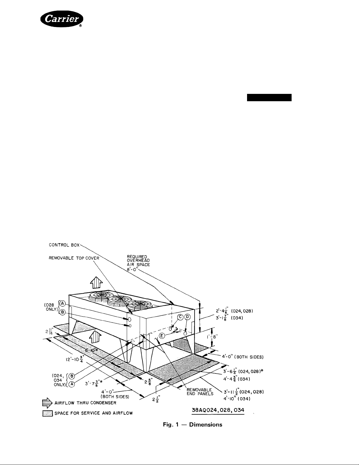
HINGED ACCESS DOOR-
'Measurements between mount
ing holes
Certified dimension drawings
available upon request
LEGEND
(38AQ024,028,034)
A — 2V2-in. Diam K O for
Suction Line
B — 1%-in. Diam K.O. for
Liquid Line (024,034)
lYz-in. Diam K.O. for
Liquid Line (028)
C — Va-in. Diam K O. for
Control Power
D — 3ya-in Diam K O for Unit
Power
E — Two %-in Diam K O. for
Defrosf Interlock Wiring
Manufacturer reserves the right to discontinue, or change at any time, specifications or designs without notice and without incurring obligations.
Book
Tab
5a
PC111
Catalog No 533-846
PrintedinUSA Form 38AQ-9SI
For replacement items use Carrier Specified Parts
Pgi
1-89
Replaces: 38AQ-5SI
Page 2
• Allow sufficient space for airflow clearance, wiring,
refrigerant piping and servicing unit. See Fig. 1.
• Locate unit so that condenser airflow is unrestrieted
on all sides and above.
• Unit has legs for mounting on level pad. See Fig. 2
and Table 1 for weight distribution based on
recommended support points.
NOTE: If vibration isolators are required for a par
ticular installation, use the data in Table 1 and Fig. 2
to make proper selection.
Step 2 — Rig and Locate the Unit
A CAUTION
Be sure unit panels are securely in place prior to
rigging. Be careful rigging, handling and installing
unit. Improper unit location can cause system mal
function and material damage.
RIGGING — Lift units at points 3, 4, 7, 8 (Fig. 2). Use
eyebolts and washers supplied in parts package. Do not
sling unskidded unit. Skidded unit may be slung provided
sling does not contact sides of unit. While unit is on skid,
it can be rolled or dragged.
IMPORTANT: SPREADER BARS MUST BE USED BETWEEN POINTS
2 8 4 6
3-4 AND 7-8
+
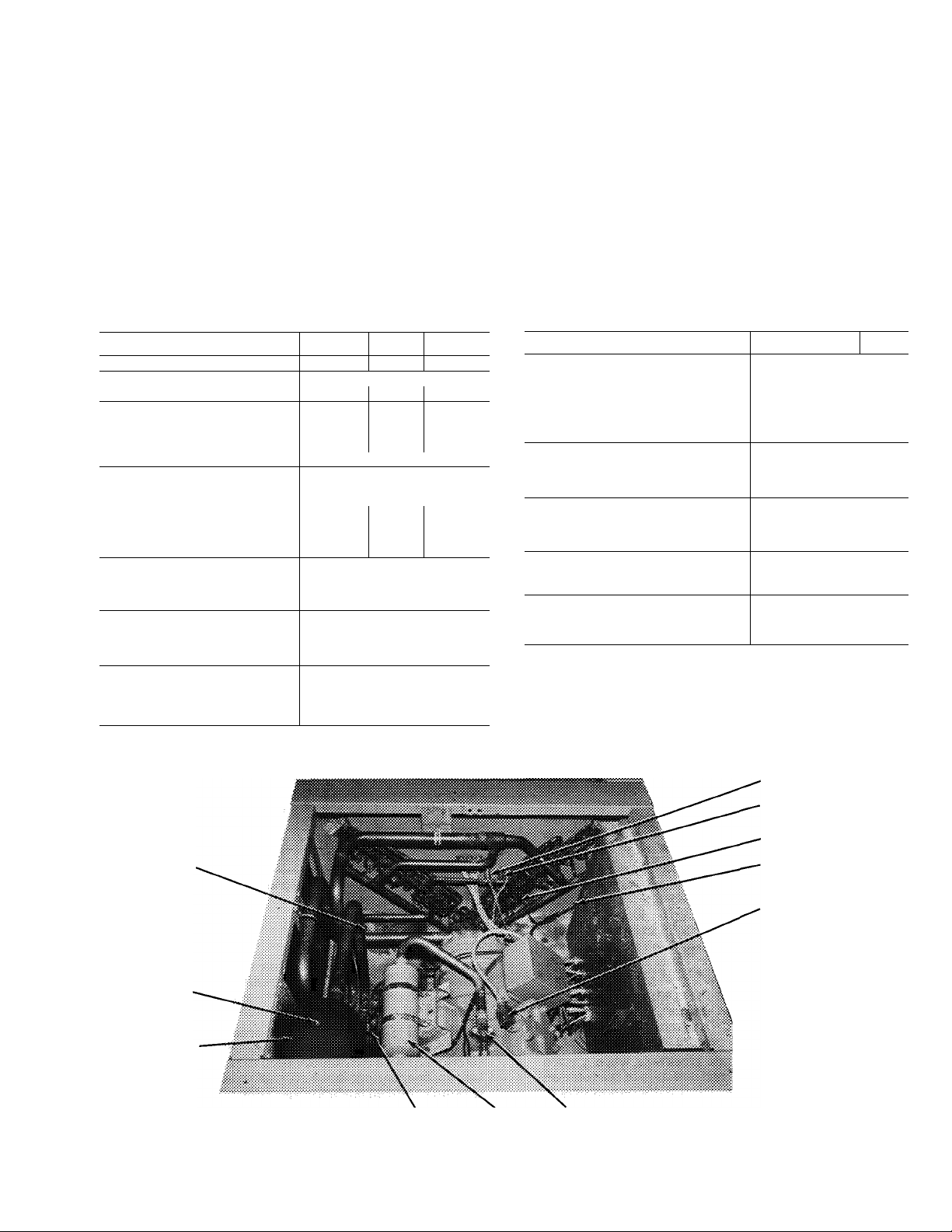
Step 3 — Mount Compressor
COMPRESSOR MOUNTING — As shipped, the com
pressor is held down by special self-locking bolts and
lockwashers. After unit is installed, remove self-locking
bolts one at a time and reassemble with flanged washers
and neoprene snubbers as shown in Fig. 4. The flanged
washers and neoprene snubbers are shipped in a cloth
bag tied to one of the compressor feet. Tighten all 4
bolts, then loosen each until the flanged washer can be
moved sideways with finger pressure.
Step 4 — Complete
Refrigerant Piping
Connections
SIZE REFRIGERANT LINES — Consider length of
piping required between outdoor and indoor units,
amount of liquid lift and compressor oil return. Refer to
Part 3 of Carrier System Design Manual for line sizing
information. Refer to indoor unit installation instruc
tions for additional information.
Maximum liquid line length is 100 feet. Carefully
determine the minimum expected unit capacity and size
interconnecting lines accordingly. For low load condi
tions, determine if there is a need for double suction
risers per Carrier System Design Manual. Consider vapor
line as hot gas line. Consider line sizes for heating as well
as cooling capacities.
A CAUTION
Piping must be properly sized and installed for the
system to operate efficiently.
COIL
SECTION
COMPR
SECTION
+
TOP VIEW
Bo LEG LOCATIONS -H LIFTING POINTS
Fig. 2 — Weight Distribution
PLACING UNIT — Place unit so that airflow is un
restricted above. Provide clearance around the unit as
shown in Fig. 1. Remove 6 hold-down bolts, releasing
skid. The legs are attached to base skid.
Block up or suspend unit. With bolts supplied, secure
legs (see Fig. 5) to unit (1, 2, 3, 4, 5 and 6 in Fig. 2 and
Table 1).
Table 1 — Weights
UNIT
38AQ
TOTAL
1
024
028 2160 203
034 2500 286 286 834
2040
204 204
The unit may be mounted on a full pad or on raised
supports at each leg. Weight distribution shown in Fig. 2
will determine type of support required. Bolt unit securely
to pad or supports when positioned and leveled.
WEIGHT (lb)
Leg Location
2
3
670
203 592
4
5 6
670 146 146
642 235 285
834
130 130
FILTER DRIERS — 38AQ units have factory-installed
filter driers. It is not necessary to add filter drier and check
valve arrangements in interconnecting piping. It is recom
mended that a field-supplied liquid moisture indicator be
installed in liquid line. Indoor units provide filter driers
with heat pump piping packages, for field installation.
Refer to indoor unit installation instructions for details.
Complete refrigerant piping from indoor coil to out
door coil before opening liquid and suction lines at the
heat pump unit. See Table 3 for proper refrigerant charge
and piping selection data.
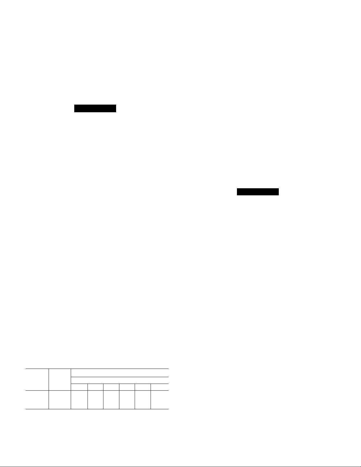
PROVIDE SAFETY RELIEF — A fusible plug is
located on the liquid line before the liquid valve and on
top of the accumulator (Fig. 3). DO NOT CAP THIS
PLUG. If local code requires additional safety devices,
install as directed.
HEAD PRESSURE CONTROL — Fan cycling for head
pressure control is a standard offering but functions in
cooling mode only. The no. 2 fan cycles as a function of
liquid pressure sensed by fan cycling pressure switch
(FCPS). Fan no. 3 cycles as a function of outdoor air
temperature through the action of the air temperature
switch (ATS). See Table 2 for settings. These switches are
automatically bypassed in heating mode. Table 4 shows
minimum outdoor ambient temperatures at which units
will operate and provide full cooling capacity.
RECEIVER — No receiver is provided with the unit; it
is recommended that one not be used.
PIPING PROCEDURE — Do not remove caps from
vapor and liquid line stubs in compressor compartment
until piping connections are ready to be made. Pass nitro
gen or other inert gas through piping while brazing, to
prevent formation of copper oxide.
Install thermostatic expansion valves in liquid line
ahead of each indoor coil section.
Page 3
SUCTION PIPING AT INDOOR COIL AND TXV
BULB LOCATION — The purpose of these recom
mendations is to achieve good mixing of refrigerant
leaving indoor coil suction header for proper sensing by
the TXV bulb.
1. A minimum of two 90° elbows must be installed
upstream of the expansion valve bulb location.
2. The TXV sensing bulb should be located on a vertical
riser where possible. If a horizontal location is neces
sary, secure the bulb at approximately the 4 o’clock
position.
3. Size suction line from indoor coil through the riser
for high velocity. Enter suction pipe sizing charts in
Table 2 — Physical Data
the Carrier System Design Manual at design tons
and equivalent length (for 2 F loss). If reading falls
between 2 sizes on chart, choose the smaller pipe size.
Suction piping for the high velocity section should be
selected for about 0.5 F friction loss. If a 2 F loss is
allowed for the entire suction line, 1.5 F is left for the
balance of the suction line and it should be sized on
that basis. Check that high-velocity sizing is adequate
for oil return up the riser.
When the compressor is below indoor coil, the riser
at indoor coil does not have to extend as high as the
top level. After a 15 diameter riser has been provided,
suction line may elbow down immediately.
UNIT 38AQ 024 028 034
14
35 4
2160
R-22
61
4
19
39 0 49 6
1
426 ± 7
5 ±3
20 ±5
2500
06E2275
6 6
24 000
OPERA TING WEIGHT (lb) 2040
REFRIGERANT
Operating Charge (ib)* 55
COMPRESSOR
Model No 06E2250 06E6265
Cylinders
Oil (pts)
Crankcase Heater (watts) 180
OUTDO OR AIR FANS
Number 3
Rpm; 60-Hertz 1140 (3-Ph); 1075 (Single-Phase)
Diameter (in ) 26 30 30
Motor Hp
Cfm 15 000 24 000
Kilowatts 3 4 3 4 3 6
OUTDO OR COIL
Rows Deep . Fins/Inch 3 15
Face Area (sq ft)
Storage Capacity (lb|t 70
CONTR OLS
High Press Switch (HPS)
Cutout (psig)
Cut-in (psig) 320 ±20
Loss-of-Charge Switch (LC S) —
Liquid Line
Cutout (psig)
Cut-in (psig)
FUSIBLE PLUG
3/4 1 1
UNIT38AQ
CONTR OLS (cont)
71
19
99
Fan Cycling Press Switch (FCPS)—
No 2 Fan Cycling
Opens (psig)
Closes (psig) 257 '¿S
THERM OSTAT
Defrost Therm ostat (DFT)
Opens (F)
Closes (F)
Fan Cycling Thermostat (ATS) —
No 3 Fan Cycling
Opens (F)
Closes(F)
FUSIBLE PLUG SETTING
Liquid Line (F)
Accumulator (F)
OIL PRESS SAFETY SW ITCH (OPS)
Set Point (psig)
Differential (psig)
'Approximate charge with 25 ft of interconnecting piping Use appropriate
charging charts for actuai charging of unit
fRefrigerant storage capacity at 120 F condensing temperature with con
denser 80% fuli of iiquid
LOSS-OF-CHARGE SWITCH
FAN CYCLING PRESSU RE
SWITCH
DEFROST THERMOSTAT
AIR TEMPERATU RE
SWITCH
024 1 028 034
126 ±4
65 ±5
28 ±3
70 ±3
83 max
210 ±10
170 ±10
9
28
FUSiBLE PLUG
ACCUMULATOR
MUFFLER COMPRESSOR
SERVICE
VALVE
Fig. 3 — Component Locations
COMPRESSOR UNLOADER
SOLENOID
Page 4
SNUBBER FLANGED
WASHER
Table 3 — Refrigerant (R-22) Charge and
Piping Selection Data
. neoprene
SNUBBER
ISOLATION SPRING
Fig. 4 ~ Compressor Mounting
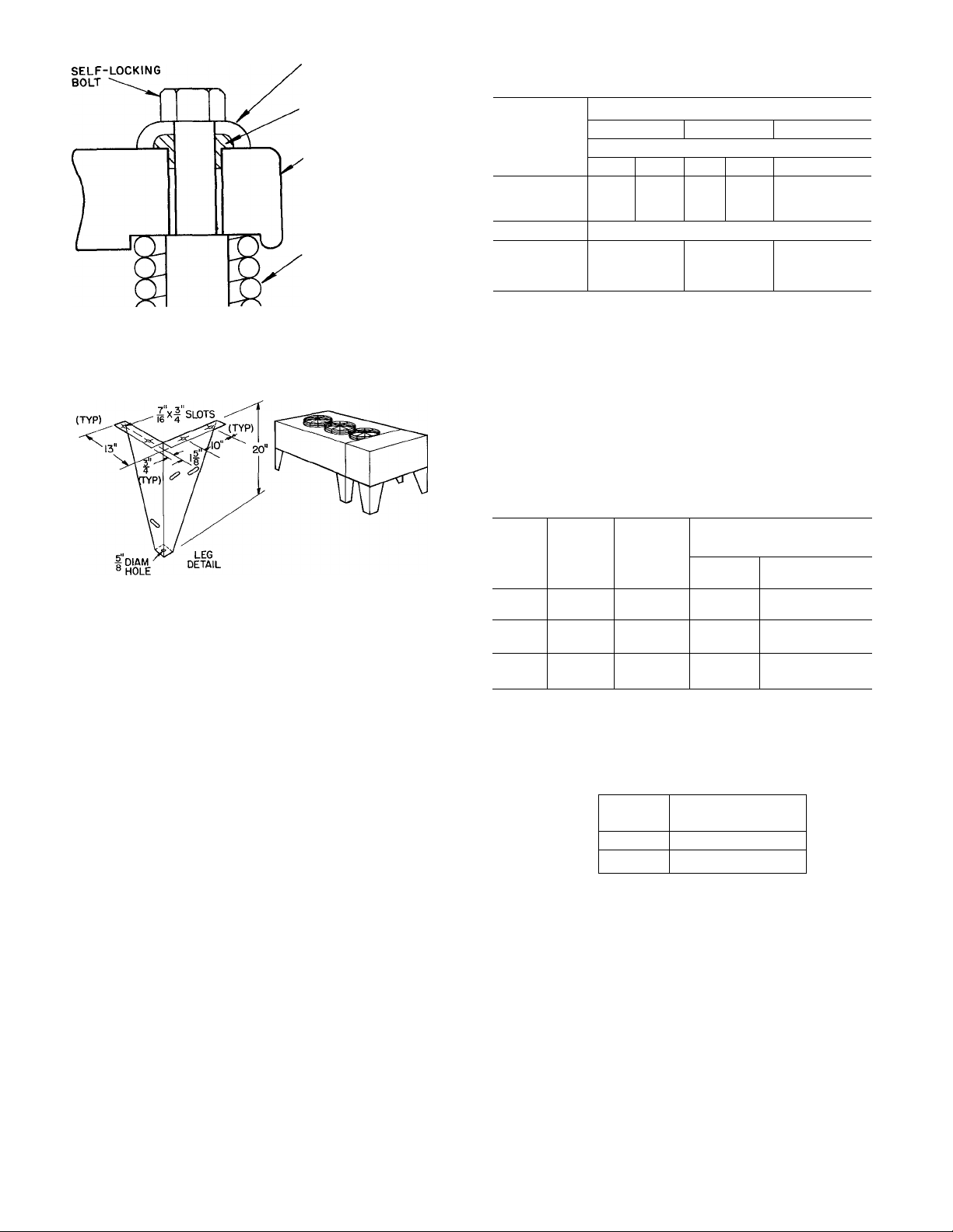
NOTES
1 For mounting dimensions, see Fig 1.
2 Parts package contains all fasteners required for assem
bling 20-in. legs to unit
Fig. 5 — Mounting Legs for 38AQ Units
LENGTH OF PIPING (ft)*
OUTDOOR
UNIT
38AQ
024
028
034
0-25
L
V
%
1%
%
1%
%
U/s
26-60
Line Size (in. O.D.)
L V
1%
%
1%
%
2'/8
%
61-100t
L V
% 1 %
Vb 2 Va
% 2'/8
Approximate System Charge (lb)t
024
028 61
034
L — Liquid Line V — Vapor Line
'Approximately 4 elbows assumed in determining pipe sizes
fMaximum length of interconnecting piping is 100 feet.
^Approximate system charge is for estimating only It includes
charge requirements for one outdoor unit, matching indoor coil,
and interconnecting piping System should be charged in
accordance with installation instructions
NOTE Maximum liquid line size is %-in OD Maximum R-22
system charge is 85 lb (024), 95 lb (028), 105 lb (034)
55
71
58
65
79
75
83
93
Table 4 — Minimum Outdoor Air Operating
Temperature
MINIMUM OUTDOOR
UNIT COMPR
38AQ
024
028
034
CAP. (%)
100
50
100
67
100
67
CONO
TEMP (F)
90 28 -20
80
90
80
90 30 -20
80 33 -20
TEMPERATURE (F)*
Std Unit
Motormaster®
41
34
37
32LT
-20
-20
-20
.4^
Step 5 — Make Electrical Connections
POWER SUPPLY — Electrical characteristics of avail
able power supply must agree with nameplate rating.
Supply voltage must be within tolerances shown in
Tableó. See Fig. 6 for System Label Diagram. Phase
unbalance must not exceed 2%. Operation of unit on
improper supply voltage or with excessive phase un
balance constitutes abuse and is not covered by Carrier
Warranty.
POWER WIRING — All power wiring must comply
with applicable local requirements and National Elec
trical Codes. Install a field-supplied branch circuit dis
connect switch of a type that can be locked OFF or
OPEN. Run power wires from disconnect switch through
unit power opening (D on Fig 1 ) and connect to terminal
block just inside opening. See Table 5 for maximum
allowable wire size.
Power terminal block is in the control box. Remove
outer panel and #10 screw on the door. Swing door open,
remove screws on barrier panel and remove barrier panel.
Replace barrier panel when power wiring is completed.
Condenser fans must rotate clockwise when viewed
from above. If necessary, correct direction of fan rotation
by reversing any 2 power input wires at disconnect switch.
Affix crankcase heater decal to unit disconnect switch.
CONTROL CIRCUIT WIRING — Internal control
voltage on 38 AQ units is both 115-volts and 24-volts. All
control circuit wiring must comply with applicable local
'Applies to cooling mode of operation only
Table 5 — Maximum Allowable Field Wire Sizes
UNIT
38Aa
024,028,034
Terminal Block (with integral compression terminal)
TB
and national codes. Route remote control wiring to unit
control box through control opening (C on Fig. 1) and
connect to control terminal block inside the control box.
All external control wiring is 24-volt, NEC Class 2.
SAIL SWITCH — It is highly recommended that an
indoor airflow switch (field installed) be installed and
interlocked with the outdoor unit, to prevent the outdoor
unit from operating in the event of indoor airflow failure
(example: broken fan belt). Operation of compressor with
no indoor airflow causes compressor to operate in a
vacuum which can damage bearing surfaces. Therefore,
install a field-supplied sail switch in the supply air duct
work of the mating indoor fan coil unit, and wire to
outdoor unit. See Fig 7.
VOLTS
(60-Hz)
208/230
460, 575
WIRE SIZE
6 AWG to 350 MCM
14 AWG to 2/0
CONN.
TB
Page 5
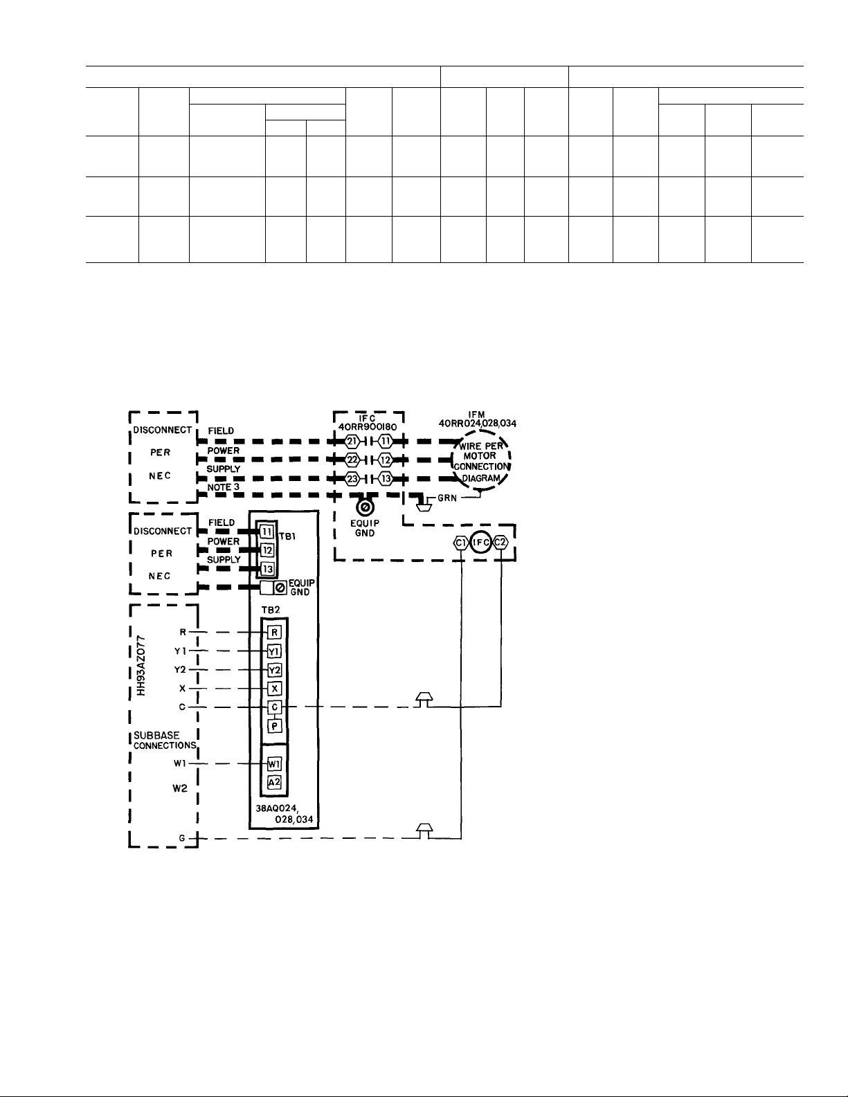
Table 6 — Electrical Data (3 Phase, 60 Hz)
UNIT
Volts
38AQ
024
028
Model
510
Nameplate
208/230 187
600 460 414
100 575
510 208/230 187
600 460
Supplied*
Min Max
518 632 41
414
MCA
253
508
103
51
253 145 225
508 69
100 575 518 632 62
034
510 208/230 187
600 460
414
253 170
508 72
100 575 518 632 64
FLA — Full Load Amps (fan motors)
LRA — Locked Rotor Amps
MCA — Minimum Circuit Amps Compiles with NEC Section
MOCP — Maximum Overcurrent Protection (fuse only)
MTA — Must Trip Amps (circuit breaker)
NEC — National Electric Code
RLA — Rated Load Amps (compressor)
430-24
MOCP
175
80
60
110
100
250
110
100
COMPRESSOR
RLA
100 0 446
120 0
LRA MTA
76 0
345 53t
36 0 173
120
28 6
Total
50t 3
40t
(total)
70t 6 2
48 0 223
43.4
164
33t
6;t
3
506 84Í
50 0 253 35Í
45 0
176
63t 2 5 2 5
'Units are suitable for use on electrical systems where voltage
supplied to the unit terminals is not below or above the listed
limits
t3-Pole circuit breaker
^6-Pole circuit breaker
3 3 6
FANS
Kw
No. 1
45 4 6
3 4 1 9
1 6
34
3 0
2.5 2.5
6 2
30 3 0 3 0
FLA (ea)
No 2 No. 3
1 9 1 9
1.6 1.6
6 6 6 6
3 0 3 0
6 6 6 6
46
2.5
2 5
Fig. 6 — System Label Diagram; 38AQ024,028,034
NOTES ,—I
1 Locate blue wire between [jJ on TB2B and terminal 7 of CR3
and cut
2 Splice airflow switch (AFS) (field supplied) contact wires (field
provided) to 2 ends of cut blue wire as depicted
AFS — Airflow switch (sail switch)
----------
Factory Wiring
-----------
Field Wiring
Fig. 7 — Field Wiring for Airflow Switch. 38AQ024, 028 or 034/40RR
TB2B
LEGEND
Equip Gnd — Equipment Ground
IFC — Indoor Fan Contactor
IFM — Indoor Fan Motor
TB — Terminal Block (Board)
NOTES
1 This diagram applies to the follow
ing systems. 40RR024 with 38AQ
024, 40RR028 with 38AQ028 and
40RR034 with 38AQ034.
2. For wiring details of components,
see schematic in each component
3 Use copper conductors only for IFM
wiring
^SPLICE^
BLU
BLU
I I
I AFS I
CR3
Page 6

START-UP
Before Starting Unit, check the following:
1. Compressor oil level must be visible in the compressor
oil sight glass. Add oil if necessary. (See Oil Charge.)
2. Compressor hold-down bolts must be snug but not
tight.
3. All internal wiring connections must be tight; all
barriers and covers must be in place.
4. Electrical power sources must agree with unit name
plate rating.
5. All service valves must be open.
6. Crankcase heater must be firmly locked into com
pressor erankcase. Crankcase heater is inserted at the
factory with thermal conductive grease.
Evacuate and Dehydrate entire refrigerant system
as described in the Carrier Standard Service Techniques
Manual, Chapter 1, Section 1-7.
Leak Test entire refrigerant system by the pressure
method described in the Carrier Standard Service Tech
niques Manual, Chapter 1, Section 1-6. Use refrigerant
specified for unit at approximately 25 psig backed up with
an inert gas to a total pressure not to exceed 200 psig.
Energize Branch Circuit — Close field disconnect
switch to energize compressor crankcase heater. Set
room thermostat to prevent unit(s) from starting at this
time.
Heating/Cooling Thermostat (HH07AT072)
has an adjustable heat anticipator for both first- and
second-stage heating circuits.
SETTINGS — Set adjustment lever for first-stage anti
cipator at 0.79 (left-hand side). Set adjustment lever for
second-stage anticipator at 0.42 (right-hand side).
NOTES:
1 All 3 outdoor fans must be operating
2 To be used with approved 40RR combinations only
3 Applies to all approved combinations
Fig. 8 — Cooling Cycle Charging Chart, 40RR/38AQ024
Page 7

To Charge System — Refer to Carrier Standard
Serviee Teehniques Manual, Chapter 1 and the pro-
eedures described below. Use Fig. 8 for charging any
40RR/38AQ024 combination; Fig. 9 for charging any
40RR/38AQ028 combination; and Fig. 10 for charging
any 40RR/38AQ034 combination.
A CAUTION
Charge unit in cooling mode only. Charging unit
in heating mode could result in overcharging.
3. Allow system to operate for 20 minutes.Take tem
perature and pressure readings at liquid service valve
and check values with the charging chart.
4. Measure liquid line temperature close to the liquid
service valve, and the pressure at the Schrader port on
the liquid line service valve. Plot point on the charging
chart. If point is above the line, add charge. If point
is below the line, remove charge until operating point
falls on the line.
5. Record final refrigerant charge on unit nameplate.
1. Use Refrigerant R-22 only.
2. Regulate refrigerant drum valve to maintain suction
pressure at 80 psig while charging. Charge with vapor
only at suction side of unit.
NOTE: Do not depend on sight glass when charg
ing unit. Use charging chart.
To Start Unit — After compressor crankcase
heater has been on for at least 24 hours, set room
thermostat so unit will start on desired mode.
HEATING — Place thermostat selector at HEAT and
set temperature selector above room ambient.
COOLING — Place thermostat selector at COOL and
set temperature selector below room ambient.
NOTES:
1. All 3 outdoor fans must be operating
2 To be used with approved 40RR combinations only.
3. Applies to all approved combinations
Fig. 9 — Cooling Cycle Charging Chart, 40RR/38AQ028
7
Page 8

f
NOTES
1 All 3 outdoor fans must be operating
2 To be used with approved 40RR combinations only
3. Applies to all approved combinations.
Fig. 10 — Cooling Cycle Charging Chart, 40RR/38AQ034
Oil Charge (Table 1) — Allow unit to run for about
20 minutes. Stop unit and check compressor oil level. Add
oil only if necessary to bring oil into view in sight glass.
Use only Carrier-approved compressor oil. Approved
oils are:
Suniso 3GS
Capella B1
DuPont Synthetic
Refrigeration Oil (150 SSU only)
Zerol 150 (synthetic)
Do not reuse drained oil or use any oil that has been
exposed to atmosphere. Procedures for adding or remov
ing oil are given in Carrier Standard Service Techniques
Manual,Chapter 1, Refrigerants.
If oil is added, run unit for additional 10 minutes. Stop
unit and check oil level. If level is still low, add oil only
after determining that piping system is designed for
proper oil return and that the system is not leaking oil.
Check Operation of all safety controls. Replace
all service panels. Be sure that control panel cover is
closed tightly.
Page 9

SERVICE
Capacity Control is by one electrically actuated
unloader which controls 2 cylinders. Unloader does not
require field adjustment.
Compressor Motor Protection
CIRCUIT BREAKER — A manual reset calibrated-trip
magnetic circuit breaker protects the compressor against
overcurrent. Do not bypass connections to increase size
of breaker for any reason If trouble occurs, determine
cause and correct before resetting the breaker. Circuit
breaker Must Trip Amps (MTA) are listed in Tableó,
Electrical Data.
DISCHARGE GAS THERMOSTAT — A sensor in the
discharge gas of the compressor reacts to excessively high
discharge gas temperature and shuts off compressor.The
high temperature of discharge gas is a direct indication
of an overtemperature condition in compressor motor.
CRANKCASE HEATER — The compressor has an
electric heater located in the bottom cover, held in place
by a clip. Heater musi be tight to prevent backing out
(heater will burn out if exposed to air). The heater is
wired into compressor control circuit through a relay to
energize only when compressor shuts off. This keeps the
oil at a temperature that will prevent excessive absorption
of refrigerant during shutdown periods. Crankcase heater
is located in a lockout circuit. If crankcase heater is defec
tive, the compressor locks off Heat pump remains off
until corrective action is taken. This lockout circuit
cannot be reset by adjusting the thermostat.
Crankcase heater should be energized at all times when
unit is not running except during prolonged shutdown
or during servicing. In these cases, heater should be
energized for 24 hours before unit is restarted.
Fan Motor Protection — Fan motors are inherently
protected, grouped on a single circuit breaker.
Fan Adjustment — When replacing a fan, adjust fan
until top surface of hub plate is below top of orifice ring
as indicated in Fig 11. Then, tighten both setscrews,
located over the keyway of fan hub of motor shaft. Seal
recessed area of fan hub bore with Permagum to prevent
rusting.
Head Pressure Control reduces condensing capacity
under low-ambient conditions. For intermediate season
operation, fan cycling is employed. Fan no. 2 is cycled by
pressure control, with the pressure sensor located in the
liquid line. Fan no. 3 is cycled by an air temperature
thermostat (see Table 2).
Liquid Line Solenoid Valve closes when compressor
is off, and opens when compressor is on. The valve mini
mizes refrigerant migration during heat pump OFF cycle,
protecting against flooded starts.
Accumulator Oil Return is external. The accu
mulator drains through an extenal port at bottom of
accumulator. The port feeds an orifice which regulates the
rate of oil and refrigerant returned to the compressor. The
orifice is removable and cleanable when the system does
not contain refrigerant. The oil return mechanism also
contains a solenoid valve that opens when compressor is
ON, and closes when compressor is OFF. The oil return
solenoid does not allow liquid refrigerant to drain from
the accumulator during the heat pump OFF cycle, pro
tecting the compressor against flooded starts.
Lubrication
FAN MOTORS — Fan motors have permanently lubri
cated bearings. No provisions for lubrication are made.
COMPRESSOR — The compressor has its own oil
supply. Loss of oil due to a leak in the system should be
the only reason for adding oil after system has been in
operation.
Coil Cleaning — Clean coils with a vacuum cleaner,
fresh water, compressed air or a bristle brush (not wire).
Set up coil cleaning as part of a planned maintenance
schedule when units are installed in corrosive environ
ments. Wash all accumulations of dirt from coil in these
applications. Keep condenser coil drain holes free of dirt
and debris to ensure adequate coil drainage.
UNIT
38AO
024
028
034
DIMENSION A (in.)
Center Fan
%
1%
Fig. 11 — Fan Adjustment
End Fan
%
2%
Page 10

OPERATING SEQUENCE
(Refer to wiring diagrams in 38AQ wiring booklet)
Standby (OFF) Mode — During the standby or OFF
mode, crankcase heater is energized. Reversing valve
may Or may not be energized depending on mode of
operation (heating or cooling) when thermostat is
satisfied.
COOLING — When thermostat calls for first-stage
cooling (TCI closed), indoor fan motor starts imme
diately. Compressor and outdoor fans start between 3
seconds and 5 minutes depending on length of time unit
is off after thermostat is satisfied, due to 5-minute Time
Guard® II circuit. Outdoor fan motors nos. 2 and 3 may
or may not operate depending on position of fan cycling
pressure switch (FCPS) and air temperature switch
(ATS). The reversing valve solenoid (RVS) becomes de
energized causing reversing valve to shift to cooling
position. Crankcase heater is off. Liquid line and accu
mulator oil return solenoid valves open, allowing refrig
erant and oil flow.
Defrost Timer does not operate during cooling mode.
When thermostat calls for second-stage cooling (TC2
closed), unloader is de-energized causing compressor to
run fully loaded.
If a malfunction occurs, causing high-pressure switch
(HPS) discharge gas thermostat (DGT) or loss-of-charge
switch (LCS) to open, compressor and outdoor fans
stop and are locked out by a Signal-Loc circuit, and a
warning light comes on at the thermostat. RVS remains
de-energized so reversing valve does not shift. These
safeties reset by adjusting thermostat up to open TCI and
TC2, or by momentarily switching subbase to OFF posi
tion. When thermostat is satisfied (TCI open), com
pressor, indoor fan motors shut off. Liquid line and
accumulator oil return solenoid valves close. Reversing
valve does not shift, but remains in cooling position until
there is a call for heating. If compressor oil pressure is
lost, or if oil pressure fails to build on start-up, an oil
pressure safety switch shuts down unit. Switch must be
manually reset at the unit. DO NOT RESET MORE
THAN ONCE! If oil pressure switch trips, determine
cause and correct. DO NOT JUMPER OIL PRESSURE
SAFETY SWITCH!
Crankcase Heater is in a lockout circuit. If crankcase
heater is defective, compressor is locked off. The heat
pump remains off until corrective action is taken. This
lockout circuit cannot be reset by adjusting the thermostat.
Unit is equipped with a no-dump reversing valve
circuit. When unit is in cooling mode, reversing valve
remains in cooling mode position until thermostat calls
for heating. When unit is in heating mode, reversing valve
remains in heating mode position until thermostat calls
for cooling.
HEATING — When thermostat calls for heating (THl
closed), indoor fan motor starts. Compressor and out
door fans start between 3 seconds and 5 minutes depend
ing on length of time unit is off after thermostat is satis
fied, due to 5-minute Time Guard II circuit. Liquid line
and accumulator oil return solenoid valves open when
compressor operates, and close when compressor is OFF.
Compressor always runs fully loaded in the heating mode.
All 3 outdoor fans also run during heating mode. Revers
ing Valve Solenoid (RVS) shifts for heating operation
at start-up.
Defrost Timer runs continuously during heating mode.
Crankcase heater is off whenever compressor is on. If a
malfunction occurs, causing high-pressure switch (HPS),
discharge gas thermostat (DGT) or loss-of-charge switch
(LCS) to open, compressor and outdoor fan motors stop
and are locked out by a Signal-LOC eircuit, and a
warning light appears on the thermostat. RVS remains
energized so reversing valve does not shift. Reset lockout
system by adjusting thermostat down to open THl and
TH2, or by momentarily switching subbase to the OFF
position. If compressor oil pressure is lost or if oil pres
sure fails to build on start-up, an oil pressure safety
switch shuts down unit. Switch must be manually reset at
the unit. DO NOT RESET MORE THAN ONCE! If oil
pressure switch trips, determine cause and correct. DO
NOT JUMPER OIL PRESSURE SAFETY SWITCH!
Crankcase Heater is in a lockout circuit. If crankcase
heater is defective, compressor is locked off. The heat
pump remains off until corrective action is taken. This
lockout circuit cannot be reset by adjusting the thermo
stat. When thermostat is satisfied (THl opens), com
pressor, indoor fan motor and outdoor fan motors shut
off. Reversing valve remains in heating mode until
thermostat calls for cooling.
If outdoor ambient temperature is above approxi
mately 45 F, defrost thermostat (DFT) senses outdoor
coll temperature is above 28 F, and prevents start of any
defrost cycle. When outdoor ambient temperature is
below approximately 45 F, DFT senses outdoor coil
temperature is below 28 F and allows defrost cireuitry to
be energized every 60 minutes. When this occurs, revers
ing valve switches back to cooling position and outdoor
fans shut off. Defrost is terminated when liquid refrig
erant becomes warm enough to open defrost thermostat.
Defrost timer limits length of each defrost cycle to a
maximum of 10 minutes.
Two defrost interlock relays are provided for use on
systems having more than one 38AQ unit. When any
38AQ unit is in defrost mode, up to 2 additional 38AQ
units can be prevented from defrosting by temporarily
stopping their defrost timer motors until defrost on
another unit is completed.
Compressor and outdoor fan motor overcurrent pro
tection is achieved with circuit breakers (heating and
cooling modes). These require manual reset at the out
door unit control box.
Refer to Fig. 12 for typical 38 AQ heat pump refrigerant
circuit operation.
10
Page 11

Hot gas from compressor flows through the 4-way valve and is
directed to the outdoor coil header At the header it is con
densed and subcooled through converging circuits Refrig
erant leaves the outdoor coil by way of the check valve to the
liquid line
The refrigerant then fiows through the filter drier and feeds the
indoor coil by way of capillary tubes on each circuit
3 Each circuit evaporates the refrigerant and the circuits are
combined in the indoor coil header
4 The refrigerant then flows through the 4-way valve, accu
mulator and back to the compressor.
Hot gas from compressor flows through the 4-way valve and is
directed to the indoor coii header At the header it is con
densed and directed through subcooling circuits and out the
indoor coil check valve to the liquid iine. (The TXV’s stop
the refrigerant fiow during the heating cycle )
The refrigerant then feeds the outdoor coil by way of a strainer
and then through capiliary tubes on each circuit
NOTES:
1 Check valves are designated “A” through “D ”
2. Illustrations are typicai and do not portray exact coil circuiting
3 Check valve positions: A open, A closed.
Fig. 12 — Typical Heat Pump Operation
Each circuit evaporates the refrigerant and the circuits are
combined in the outdoor header with some of the circuits
flowing through the check valve
The refrigerant then flows through the 4-way valve, accu
mulator and back to the compressor
4 Only one outdoor coil is shown above The 38AQ024,028 and
034 have 2 coils plus 2 of each check valve shown above
11
Page 12

TROUBLESHOOTING CHART, COOLING CYCLE
Page 13

TROUBLESHOOTING CHART. HEATING CYCLE
Page 14

Manufacturer reserves the right to discontinue, or change at any time, specifications or designs without notice and without incurring obiigations.
Book
Tab
1
5a
PC 111
Catalog No 533-846 PrintedinUSA Form38AQ-9SI
For replacement items use Carrier Specified Parts.
Pg 14
1-89
Replaces: 38AQ-5SI
 Loading...