

Page 1
38APS025-065
38APD025-130
Long Line Check Valve Accessory
Installation Instructions
Part No.: 38AP-900---011, 38AP-900---012, 38AP-900---013
50/60 Hz
SAFETY CONSIDERATIONS
When installing this accessory, observe precautions in the
literature and on any labels attached to the equipment, and all
other safety precautions that may apply.
• Follow all safety codes.
• Wear safety glasses and work gloves.
• Use care in handling and installing this accessory.
WARNING
To avoid the possibility of electrical shock, open and tag all
disconnects before installing this equipment. Failure to do
so could result in severe personal injury.
INTRODUCTION
An accessory long line check valve must be installed for:
1. Any 025-030 size dual circuit unit where the evaporator is located higher than the condensing unit and the
linear line length exceeds 55 ft (16.8 m).
2. Any size dual or single circuit unit with linear line
length of 100 ft (30.5 m) or more.
The kit consists of a liquid line check valve and a bypass
check valve to prevent charge migration to compressor.
INSTALLATION
CAUTION
For all units with liquid lines of 100 ft (30.5 m) or more or
any 025-030 size dual circuit unit application where evaporator is located higher than the condensing unit and liquid
lines exceed 55 feet (16.8 m), a long line check valve must
be installed to prevent compressor failure. The long line
check valve accessory must be mounted in the liquid line
as close as possible to the condensing unit.
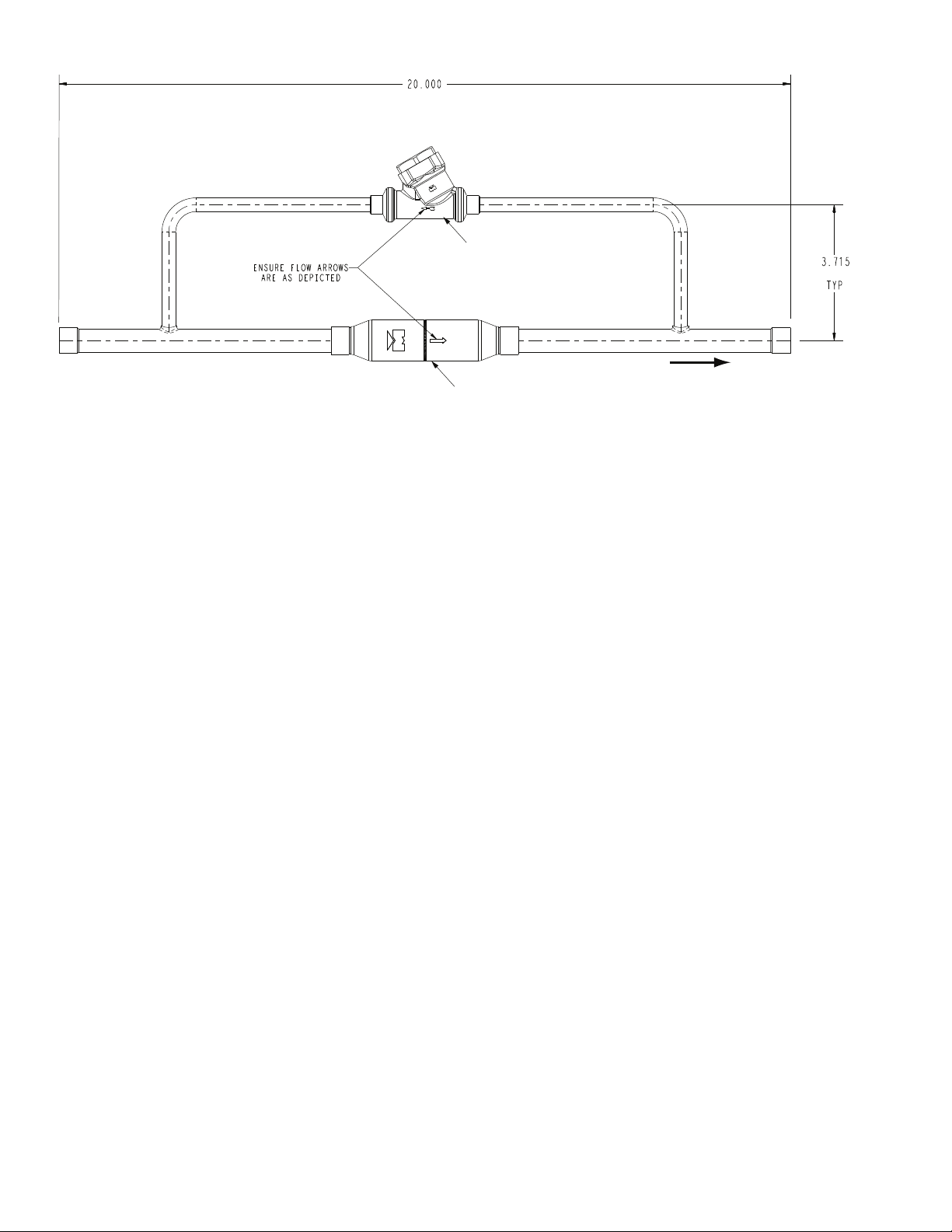
The long line check valve accessory must be mounted in the
liquid line near the condensing unit. The valve is brazed into
the liquid line. Fitting adapters may be required to connect the
check valve to the liquid line. The valve may be mounted in
any orientation, horizontally or vertically. See Fig. 1 for dimensions. Figure 2 shows the location of the check valves on a
rooftop installation. Figure 3 shows the location of the check
valves on a ground level installation.
ACCESSORY USAGE
UNIT
SIZE
38APD/S025
38APD/S027
38APD/S030
38APD/S040
38APD/S050
38APD060 Dual 5/8 + 7/8 1 1 —
38APS065 Single 7/8 — 1 —
38APD070 Dual 7/8 + 7/8 — 2 —
38APD080 Dual 7/8 + 7/8 — 2 —
38APD090 Dual 7/8 + 7/8 — 2 —
38APD100 Dual 7/8 + 7/8 — 2 —
38APD115 Dual 7/8 + 7/8 — 2 —
38APD130 Dual 7/8 + 1 1/8 — 1 1
CIRCUIT
TYPE
Dual 5/8 + 5/8 2 — —
Single 5/8 1 — —
Dual 5/8 + 5/8 2 — —
Single 5/8 1 — —
Dual 5/8 + 5/8 2 — —
Single 7/8 — 1 —
Dual 5/8 + 5/8 2 — —
Single 7/8 — 1 —
Dual 5/8 + 5/8 2 — —
Single 7/8 — 1 —
CHECK
VALVE SIZE
(in. ODF)
ACCESSORY USAGE (QUANTITY) — PART NO. 38AP-900---
011 012 013
Manufacturer reserves the right to discontinue, or change at any time, specifications or designs without notice and without incurring obligations.
Catalog No. 04-53380009-01 Printed in U.S.A. Form 38AP-5SI Pg 1 5-10 Replaces: New
Page 2
3.715
TYP
20.000
ENSURE FLOW ARROWS
ARE AS DEPICTED
BYPASS CHECK VALVE
LIQUID LINE CHECK VALVE
(508)
(94)
DIRECTION
OF FLOW
Fig. 1 — Long Line Check Valve Accessory Dimensions (Part No. 38AP-900---011 Shown)
NOTE: Dimensions are in inches. Dimensions in () are in millimeters.
2
Page 3

40RU
3 FT MAX FOR SHORT RISER
a38-7098_gs
LEGEND
*Field supplied.
†If double suction riser is required for piping
system, size short riser (3 ft [0.9 m] maximum)
according to base unit installation instructions.
**Field supplied. See base unti installation
instructions for refrigerant specialties part
numbers.
LLSV — Liquid Line Solenoid Valve
NEC — National Electrical Code
TXV — Thermostatic Expansion Valve
Piping
Double Riser Piping (if required)
NOTES:
1. All piping must follow standard refrigerant piping techniques. Refer to Carrier System
Design Manual for details.
2. All wiring must comply with the applicable local and national codes.
3. Wiring and piping shown are general points-of-connection guides only and are not
intended for, or to include all details for, a specific installation.
4. Install field-supplied disconnect switch in accordance with all local and national electrical
codes.
5. Liquid line solenoid valves (solenoid drop control) are not required but are recommended
to prevent refrigerant migration to the compressor.
6. Factory-supplied accumulator not shown.
7. Dual-circuit piping shown. Single-circuit piping is similar but would only have one suction
line and one liquid line.
8. A field-supplied (min. 5% up to 15%) bleed port TXV is required for every application.
9. Sight glass, LLSV, and filter drier are field supplied.
10. Long line length check valves are required for liquid line installation on all linear line
length applications of more than 100 ft (30.5 m). For any 025-030 size dual-circuit unit
application where evaporator is located higher than the condensing unit, check valves
are required for linear line length above 55 ft (16.8 m).
Fig. 2 — Accessory Location — 38AP Unit Rooftop Installation
3
Page 4

a38-7099_gs
NOTES:
1. All piping must follow standard refrigerant piping techniques. Refer to Carrier System
Design Manual for details.
2. All wiring must comply with the applicable local and national codes.
3. Wiring and piping shown are general points-of-connection guides only and are not
intended for, or to include all details for, a specific installation.
4. Install field-supplied disconnect switch in accordance with all local and national electrical
codes.
5. Liquid line solenoid valves (solenoid drop control) are not required but are recommended to prevent refrigerant migration to the compressor.
6. Factory-supplied accumulator not shown.
7. Dual-circuit piping shown. Single-circuit piping is similar but would only have one suction
line and one liquid line.
8. A field-supplied (min. 5% up to 15%) bleed port TXV is required for every application.
9. Sight glass, LLSV, and filter drier are field supplied.
10.Long line length check valves are required for liquid line installation on all linear line
length applications of more than 100 ft (30.5 m). For any 025-030 size dual-circuit unit
application where evaporator is located higher than the condensing unit, check valves
are required for linear line length above 55 ft (16.8 m).
LEGEND
*Field supplied.
†Field supplied. See base unit installation
instructions for refrigerant specialties part
numbers.
LLSV — Liquid Line Solenoid Valve
NEC — National Electrical Code
TXV — Thermostatic Expansion Valve
Piping
Fig. 3 — Accessory Location — 38AP Unit Ground Level Installation
Copyright 2010 Carrier Corporation
Manufacturer reserves the right to discontinue, or change at any time, specifications or designs without notice and without incurring obligations.
Catalog No. 04-53380009-01 Printed in U.S.A. Form 38AP-5SI Pg 4 5-10 Replaces: New
 Loading...