


36IBAC,N,S,M,R,L,J
Installation Instructions
Induction Beams
CONTENTS
Page
SAFETY CONSIDERATIONS . . . . . . . . . . . . . . . . . . . . . . 1
GENERAL . . . . . . . . . . . . . . . . . . . . . . . . . . . . . . . . . . . . . . . . 1
Storage and Handling . . . . . . . . . . . . . . . . . . . . . . . . . . . . 1
Initial Inspection . . . . . . . . . . . . . . . . . . . . . . . . . . . . . . . . . 1
Installation Precaution . . . . . . . . . . . . . . . . . . . . . . . . . . . 1
Codes . . . . . . . . . . . . . . . . . . . . . . . . . . . . . . . . . . . . . . . . . . . . 1
PREINSTALLATION . . . . . . . . . . . . . . . . . . . . . . . . . 1-30
Prepare Jobsite for Unit Installation . . . . . . . . . . . . . . 1
INSTALLATION . . . . . . . . . . . . . . . . . . . . . . . . . . . . 30, 31
Step 1 — Install Unit. . . . . . . . . . . . . . . . . . . . . . . . . . . . . 30
• 36IBAC
• 36IBAN
• 36IBAS,M,R,L,J
Step 2 — Connect Induction Beams
to the Piping System . . . . . . . . . . . . . . . . . . . . . . . . . . 31
Step 3 — Connect Induction Beams
to the Condensate Drainage System. . . . . . . . . . . 31
Step 4 — Connect Induction Beams
to the Primary Air Ducting System. . . . . . . . . . . . 31
ADJUSTMENT . . . . . . . . . . . . . . . . . . . . . . . . . . . . . . . . 31
Airflow Balancing Procedure . . . . . . . . . . . . . . . . . . . . 31
MAINTENANCE . . . . . . . . . . . . . . . . . . . . . . . . . . . . . . . 31
Condensate Float Switch Wiring. . . . . . . . . . . . . . . . . 31
SAFETY CONSIDERATIONS
SAFETY NOTE
Air-handling equipment will provide safe and reliable
service when operated within design specifications. The
equipment should be operated and serviced only by authorized personnel who have a thorough knowledge of system operation, safety devices and emergency procedures.
Good judgement should be used in applying any
manufacturer’s instructions to avoid injury to personnel
or damage to equipment and property.
time of delivery. Store in a clean, dry, and covered location. Do
not stack cartons. When unpacking units, care should be taken
that the inlet collars and water connections do not become
damaged.
CAUTION
Do not lift the unit by the drain pipes, water piping, or
metal duct. Units should be lifted using the mounting
brackets.
The 36IBAC unit packaging includes a base tray and an inverted box cover. Remove the box cover to fully expose the
unit.
The 36IBAN and 36IBAR units are packaged in cardboard
cartons. Open the carton top and fold the flaps back to gain access to the unit. Two people are required to lift the unit out of
the carton. These units are shipped with the grille attached, and
when setting the unit down, care must be taken to put it on a
clean, soft surface so as not to scratch the grille face.
The 36IBAS, M, L, and J units are packaged in cardboard
cartons. Open the carton top and cut the carton vertically on the
side where the duct collar is located. The grille is attached to
the unit and should not be removed. After cutting the side of
the carton, remove the unit from the box and set it on a clean
surface being careful not to scratch the grille.
Initial Inspection — Once items have been removed
from the carton, check carefully for damage to duct connections, coils, or controls. File damage claim immediately with
transportation agency and notify Carrier.
Installation Precaution — Check that construction de-
bris does not enter unit or ductwork. Accumulated dust and
construction debris distributed through the ductwork can adversely affect unit operation.
Codes — Install units in compliance with all applicable
code requirements.
PREINSTALLATION
GENERAL
The overhead induction beam distribution unit has been designed to give the customer many years of trouble free service.
Each unit contains a row or number of rows of aerodynamic
airflow nozzles located within the 20-gage heavy duty housing
assembly. These airflow nozzles deliver the proper ventilation
air from the main outdoor ventilation unit and produce an airflow profile across the coil. This aerodynamic airflow causes a
venturi effect across the coil face, which induces air from the
room across the coil surface. When cool water or hot water is
pumped through the coil, the induced airflow across the coil is
heated or cooled, then mixed with the primary airflow from the
nozzles to deliver conditioned airflow to the space.
Storage and Handling — Inspect for damage upon re-
ceipt. Shipping damage claims should be filed with shipper at
Manufacturer reserves the right to discontinue, or change at any time, specifications or designs without notice and without incurring obligations.
Catalog No. 04-53360006-01 Printed in U.S.A. Form 36IB-3SI Pg 1 3-14 Replaces: 36IB-2SI
Prepare Jobsite for Unit Installation —
time and to reduce the possibility of costly errors, set up a complete sample installation in a typical room at jobsite. Check all
critical dimensions such as pipe, wire, and duct connection requirements. Refer to job drawings and product dimension
drawings as required (see Fig. 1-28). Instruct all trades in their
part of the installation.
Refer to Tables 1-6 and Fig. 1-28 for unit data.
To save
CAUTION
Prior to hanging the unit, remove the two cotter pins holding the supply/return section to the grille frame. Failure to
remove these pins will prevent access to coils and internal
workings of the units.
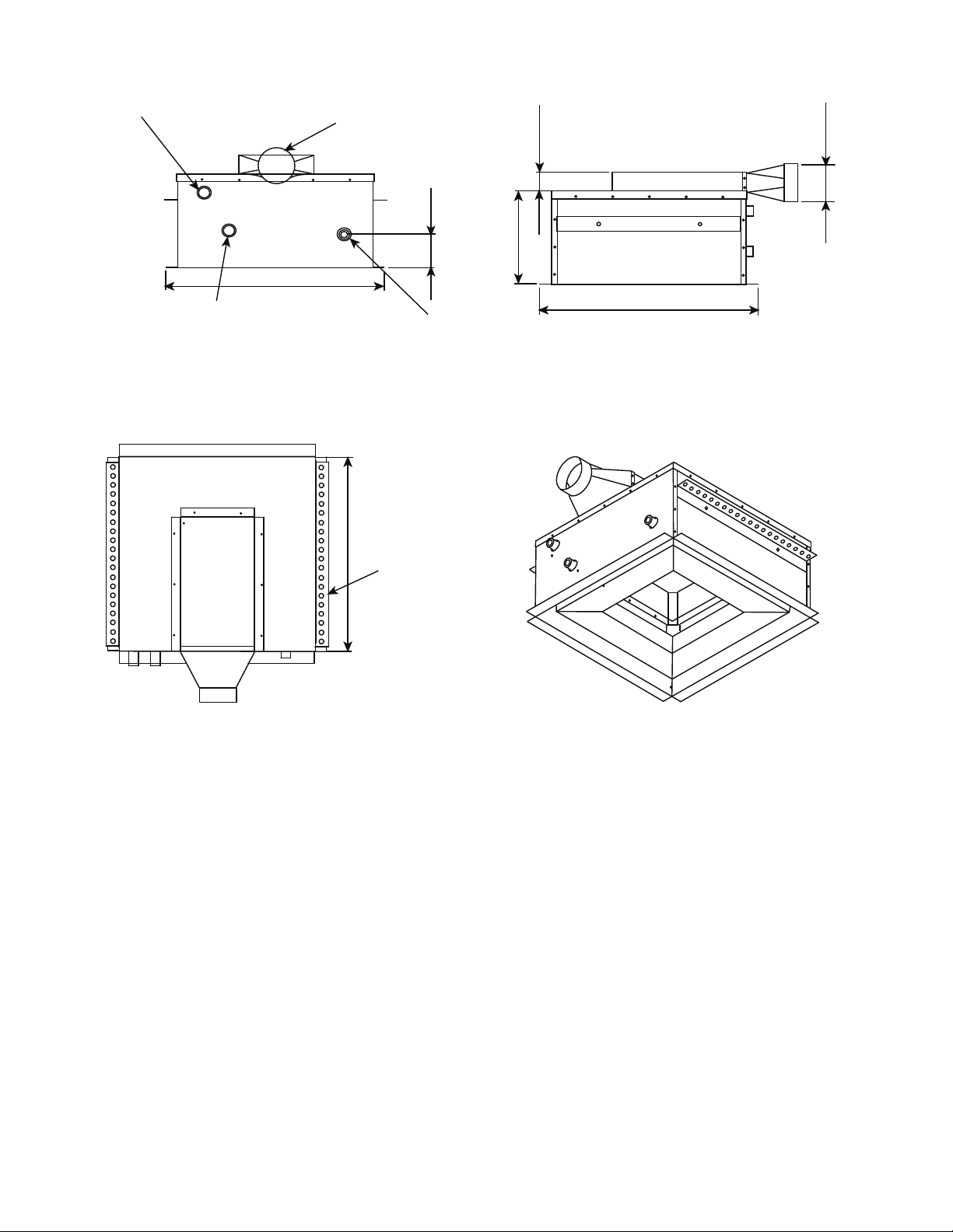
Fig. 1 — 36IBAC 2 x 2, All-Way Blow, 2-Pipe Unit Dimensions
3/4" FPT CWR/HWR
a36-579
LEGEND NOTES:
1. Dimensions shown in inches.
2. Drawing shows 2-pipe arrangement.
CWR — Chilled Water Return
CWS — Chilled Water Supply
FPT — Female Pipe Thread
HWR — Hot Water Return
HWS — Hot Water Supply
3/4" FPT CWS/HWS
TOP VIEW
FRONT VIEW
23.70
4" Ø
3.59
3/4" CONDENSATE
DRAIN
2.04
10.05
RIGHT SIDE VIEW
4.00
23.76
HANGING BAR
21.15
DIFFUSER PLATE
(SUPPLY/RETURN
GRILLE NOT SHOWN)
2

Fig. 2 — 36IBAC 2 x 2, All-Way Blow, 4-Pipe Unit Dimensions
23.76
HANGING BAR
4.00
10.05
23.76
23.70
3.59
4" Ø PRIMARY AIR
CONNECTION
3/4" FPT CWR
3/4" FPT CWS
3/4" CONDENSATE
DRAIN
12.09
1/2" FPT HWR
1/2" FPT HWS
FRONT VIEW
RIGHT SIDE VIEW
TOP VIEW
DIFFUSER PLATE
(SUPPLY/RETURN
GRILLE NOT SHOWN)
a36-580
LEGEND NOTES:
1. Dimensions shown in inches.
2. Drawing shows 4-pipe arrangement.
CWR — Chilled Water Return
CWS — Chilled Water Supply
FPT — Female Pipe Thread
HWR — Hot Water Return
HWS — Hot Water Supply
3

Fig. 3 — 36IBAC 4 x 4, All-Way Blow, 2-Pipe Unit Dimensions
3.20
4.11
17.89
3/4" Ø FPT WR
8" Ø SUPPLY AIR
3/4" PVC DRAIN
HANGING BRACKET
37.55
37.57
HANGING BRACKET
HANGING BRACKET
3/4" Ø FPT WS
FRONT VIEW
LEFT SIDE VIEW
TOP VIEW
a36-578
LEGEND NOTES:
1. Dimensions shown in inches.
2. Drawing shows 2-pipe arrangement.
FPT — Female Pipe Thread
WR — Water Return
WS — Water Supply
4

Fig. 4 — 36IBAC 4 x 4, All-Way Blow, 4-Pipe Unit Dimensions
3.20
4.11
17.89
3/4" Ø FPT CWR
1/2" Ø FPT HWR
8" Ø SUPPLY AIR
3/4" PVC DRAIN
HANGING BRACKET
35.95
36.14
HANGING BRACKET
HANGING BRACKET
1/2" Ø FPT HWS
3/4" Ø FPT CWS
FRONT VIEW
LEFT SIDE VIEW
TOP VIEW
a36-575
LEGEND NOTES:
1. Dimensions shown in inches.
2. Drawing shows 4-pipe arrangement.
CWR — Chilled Water Return
CWS — Chilled Water Supply
FPT — Female Pipe Thread
HWR — Hot Water Return
HWS — Hot Water Supply
5

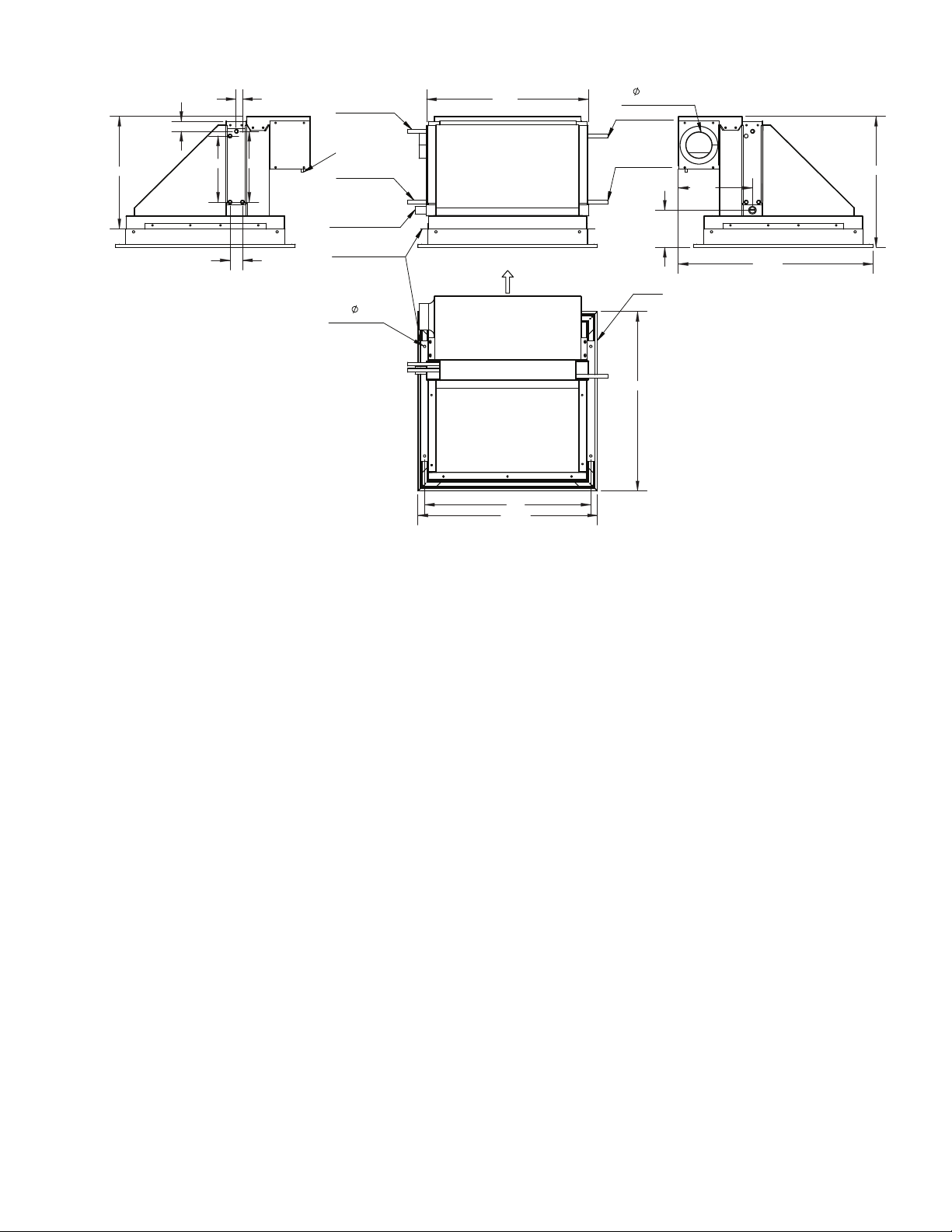
21.4
1/2" O.D. HWS/CWS
1/2" O.D. HWR/CWR
3/4" CPVC DRAIN
CONNECTION
AIR BLOW DIRECTION
23.75
23.75
22.0
GRILLE
0.31"
HOLE
TYP OF 4
H
25.78
D
9.82
4"
PRIMARY AIR
CONNECTION
8.75
.88
1.7
9.37
1.31
14.9
PRESSURE TAP
HANGER BRACKET
REAR VIEW
LEFT SIDE VIEW
RIGHT SIDE VIEW
TOP VIEW
Fig. 5 — 36IBAS 2 x 2, 1-Way Blow, 2-Pipe LH Unit Dimensions
a36-592
LEGEND NOTES:
1. Dimensions shown in inches.
2. Drawing shows 2-pipe arrangement, left-hand piping connection; right hand connection would be opposite.
3. Hand is determined by standing on the front side of the unit
with the supply air blowing against the back of your head.
4. Front face of the unit is determined by the nozzle side (supply
air) side of the unit.
CWR — Chilled Water Return
CWS — Chilled Water Supply
HWR — Hot Water Return
HWS — Hot Water Supply
6
21.4
1/2" O.D. CWS
1/2" O.D. CWR
1/2" O.D. HWS
1/2" O.D. HWR
3/4" CPVC DRAIN
CONNECTION
AIR BLOW DIRECTION
23.75
23.75
22
GRILLE
0.31"
HOLE
TYP OF 4
H
25.78
D
9.82
4"
PRIMARY AIR
CONNECTION
8.75
.88
1.7
9.37
1.31
14.9
PRESSURE TAP
HANGER BRACKET
RIGHT SIDE VIEW LEFT SIDE VIEW
REAR VIEW
TOP VIEW
a36-593
Fig. 6 — 36IBAS 2 x 2, 1-Way Blow, 4-Pipe LH Unit Dimensions
LEGEND NOTES:
1. Dimensions shown in inches.
2. Drawing shows 4-pipe arrangement, left-hand piping connection; right hand connection would be opposite.
3. CW piping connection determines the hand of the unit.
4. Hand is determined by standing on the front side of the unit
with the supply air blowing against the back of your head.
5. Front face of the unit is determined by the nozzle side (supply
air) side of the unit.
CWR — Chilled Water Return
CWS — Chilled Water Supply
HWR — Hot Water Return
HWS — Hot Water Supply
7
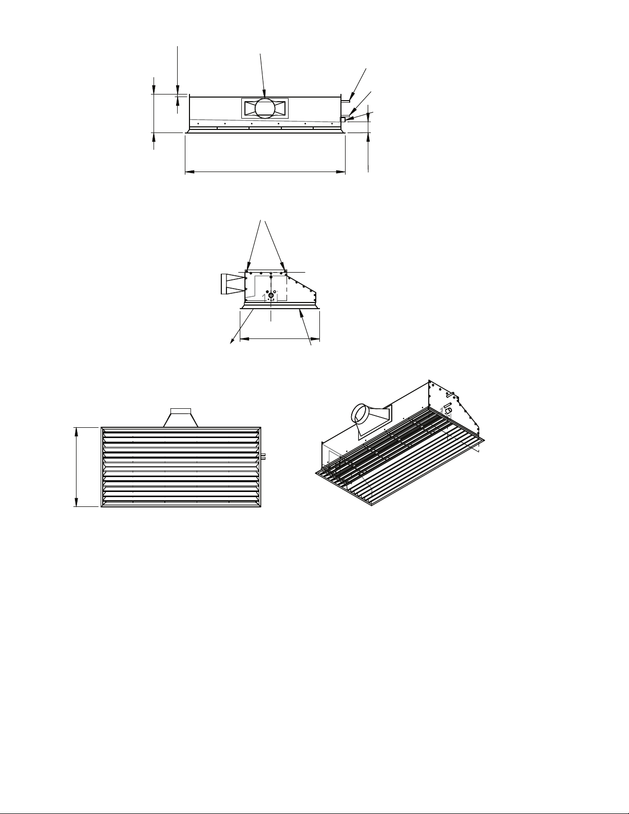
Fig. 7 — 36IBAN 2 x 4, 1-Way Blow, 2-Pipe LH Unit Dimensions
11.52
a36-571
LEGEND NOTES:
1. Dimensions shown in inches.
2. Drawing shows 2-pipe arrangement, left-hand piping connection; right hand connection would be opposite.
3. CW piping connection determines the hand of the unit.
4. Hand is determined by standing on the front side of the unit
with the supply air blowing against the back of your head.
5. Front face of the unit is determined by the nozzle side (supply
air) side of the unit.
CWR — Chilled Water Return
CWS — Chilled Water Supply
FPT — Female Pipe Thread
HWR — Hot Water Return
HWS — Hot Water Supply
6" Ø PRIMARY AIR CONNECTION
1/2" Ø FPT CWR/HWR
0.75
1/2" Ø FPT CWS/HWS
3/4" PVC DRAIN
92.3
47.75
FRONT VIEW
HANGING BRACKET
Ø 0.50
Ø 0.50
23.75
23.75
SUPPLY AIR
BOTTOM VIEW
LEFT SIDE VIEW
RETURN AIR
SUPPLY/RETURN GRILLE
WITH OPTIONAL LOUVERED
SUPPLY AND RETURN
FACE SHOWN
8

Fig. 8 — 36IBAN 2 x 4, 1-Way Blow, 4-Pipe LH Unit Dimensions
1/2" FPT HWR
a36-574
LEGEND NOTES:
1. Dimensions shown in inches.
2. Drawing shows 4-pipe arrangement, left-hand piping connection; right hand connection would be opposite.
3. CW piping connection determines the hand of the unit.
4. Hand is determined by standing on the front side of the unit
with the supply air blowing against the back of your head.
5. Front face of the unit is determined by the nozzle side (supply
air) side of the unit.
CWR — Chilled Water Return
CWS — Chilled Water Supply
FPT — Female Pipe Thread
HWR — Hot Water Return
HWS — Hot Water Supply
11.52
1/2" FPT HWS
1/2" Ø HANGING HOLES
TYPICAL OF 4
1/2" FPT CWR
1/2" FPT CWS
12.00
3/4" PVC DRAIN
93.
FRONT VIEW
3
12.50
57.9
00.9
7.75
6" Ø
RETURN AIR
RIGHT SIDE VIEW
23.75
6" Ø PRIMARY AIR
CONNECTION
TOP VIEW
23.75
47.75
SUPPLY AIR
9
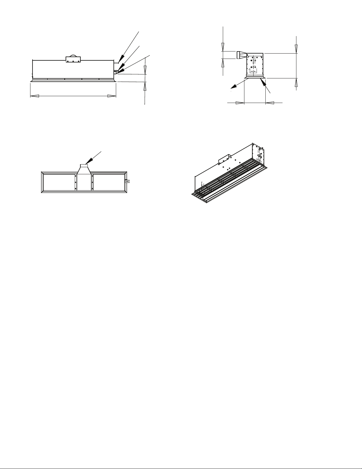
Fig. 9 — 36IBAN 1 x 4, 1-Way Blow, 2-Pipe RH Unit Dimensions
47.75
62.4
1/2" FPT WR
1/2" FPT WS
3/4" PVC DRAIN
CONNECTION
4" Ø DUCT CONNECTION
4.00
11.75
13.89
SUPPLY AIR
RETURN AIR
REAR VIEW
LEFT SIDE VIEW
TOP VIEW
SUPPLY/RETURN GRILLE
WITH OPTIONAL LOUVERED
SUPPLY AND RETURN
FACE SHOWN
a36-573
LEGEND NOTES:
1. Dimensions shown in inches.
2. Drawing shows 2-pipe arrangement, right-hand piping connection; left hand connection would be opposite.
3. Hand is determined by standing on the front side of the unit
with the supply air blowing against the back of your head.
4. Front face of the unit is determined by the nozzle side (supply
air) side of the unit.
FPT — Female Pipe Thread
WR — Water Return
WS — Water Supply
10
 Loading...