

35L,N Dual Duct Terminal Units
Variable Volume System
Installation and Start-Up Instructions
CONTENTS
Page
SAFETY CONSIDERATIONS ...................... 1
PRE-INSTALLATION.............................. 2
General ..........................................2
Warranty ......................................... 2
CONTROL ARRANGEMENTS................... 2-7
CCN Control Arrangement........................3
Analog Electric Control Arrangement ............ 3
Direct Digital Electronic Control
Arrangement (Field Supplied)................... 3
Pneumatic Control Arrangement .................3
No Control ....................................... 3
INSTALLATION ................................. 3-6
Step 1 — Install Volume Control Box .............3
Step 2 — Make Duct Connections ................3
Step 3 — Install Sensors and Make Field
Wiring Connections — Electronic Analog
or DDC (Direct Digital Controls) ................3
CONTROL SET UP ..............................6,7
General ..........................................6
Set Points ........................................6
Field Adjustments of Minimum and
Maximum Airflow Set Points ................... 6
System Calibration of the Linear Averaging
Flow Probe.....................................6
PNEUMATIC CONTROLS ........................7,8
Preparation for Balancing ........................7
Balancing Procedure
(Control Sequences 1500-1523) ................ 7
Preventative Maintenance ........................ 8
Pneumatic Control Troubleshooting..............8
ANALOG CONTROLS ..........................9,10
Balancing Procedures
(Control Sequences 2400, 2440 and 2470) ......9
Applications for Dual Duct (Minimum Air
from Cold Duct) .................................. 9
Analog Control Troubleshooting ................ 10
ComfortID™ CONTROLS ..................... 10-18
Install Sensors and Make
Field-Wiring Connections .....................10
• GENERAL
• SUPPLY-AIR TEMPERATURE SENSOR
INSTALLATION
• SPACE TEMPERATURE SENSOR INSTALLATION
AND WIRING
• WIRING THE SPACE TEMPERATURE SENSOR
AND SET POINT ADJUSTMENT SLIDEBAR
• WIRINGTHECCNNETWORKCOMMUNICATION
SERVICE JACK
• PRIMARY AIR TEMPERATURE SENSOR
INSTALLATION
• INDOOR-AIR QUALITY SENSOR INSTALLATION
• INDOOR-AIR QUALITY SENSOR WIRING
• HUMIDITY SENSOR (Wall-Mounted) INSTALLATION
Connect the CCN Communication Bus..........15
• COMMUNICATION BUS WIRE SPECIFICATIONS
• CONNECTION TO THE COMMUNICATION BUS
ComfortID Controls Start-Up ....................16
• GENERAL
• PRIMARY SYSTEM CHECK
• COMFORTID CONTROL SYSTEM CHECK
CCN System Start-Up ........................... 17
• COMFORTID TEST AND BALANCE TOOL
SOFTWARE
• COMFORTID CONSTANT VOLUME DUAL DUCT
CONTROL PACKAGE NO. 4160
• COMFORTID VARIABLE AIR VOLUME DUAL
DUCT WITH CONSTANT MINIMUM COLD DECK
AIRFLOW CONTROL PACKAGE NO. 4170
• COMFORTID VARIABLE AIR VOLUME DUAL
DUCTWITHCOLDDECKCLOSE-OFFCONTROL
PACKAGE NO. 4175
• COMFORTID VARIABLE AIR VOLUME DUAL
DUCT WITH CONSTANT VENTILATION CONTROL
PACKAGE NO. 4180
• COMFORTID VARIABLE AIR VOLUME DUAL
DUCT WITH DEMAND CONTROL VENTILATION
CONTROL PACKAGE NO. 4190
SAFETY CONSIDERATIONS
SAFETY NOTE
Air-handling equipment will provide safe and reliable
service when operated within design specifications. The
equipment should be operated and serviced only by authorized personnel who have a thorough knowledge of system
operation, safety devicesand emergency procedures.
Good judgement should be used in applying any manufacturer’s instructions to avoid injury to personnel or damage to equipment and property.
Disconnect all power to the unit before performing maintenance or service. Unit may automatically start if power is
not disconnected. Electrical shock and personal injury
could result.
Manufacturer reserves the right to discontinue, or change at any time, specifications or designs without notice and without incurring obligations.
Book 3
Ta b 6 a
Catalog No. 04-53350001-01 Printed in U.S.A. Form 35L,N-1SI Pg 1 3-06 Replaces: 35L,M,N-1SI

PRE-INSTALLATION
General —
The 35L,N units are dual duct terminals available with factory-installed pneumatic, analog, and Carrier
ComfortNetwork®(CCN)DirectDigitalControl(DDC)
control options. See Table 1. Figure 1 shows the basic box.
Figure 2 is an example of a unit identification label.
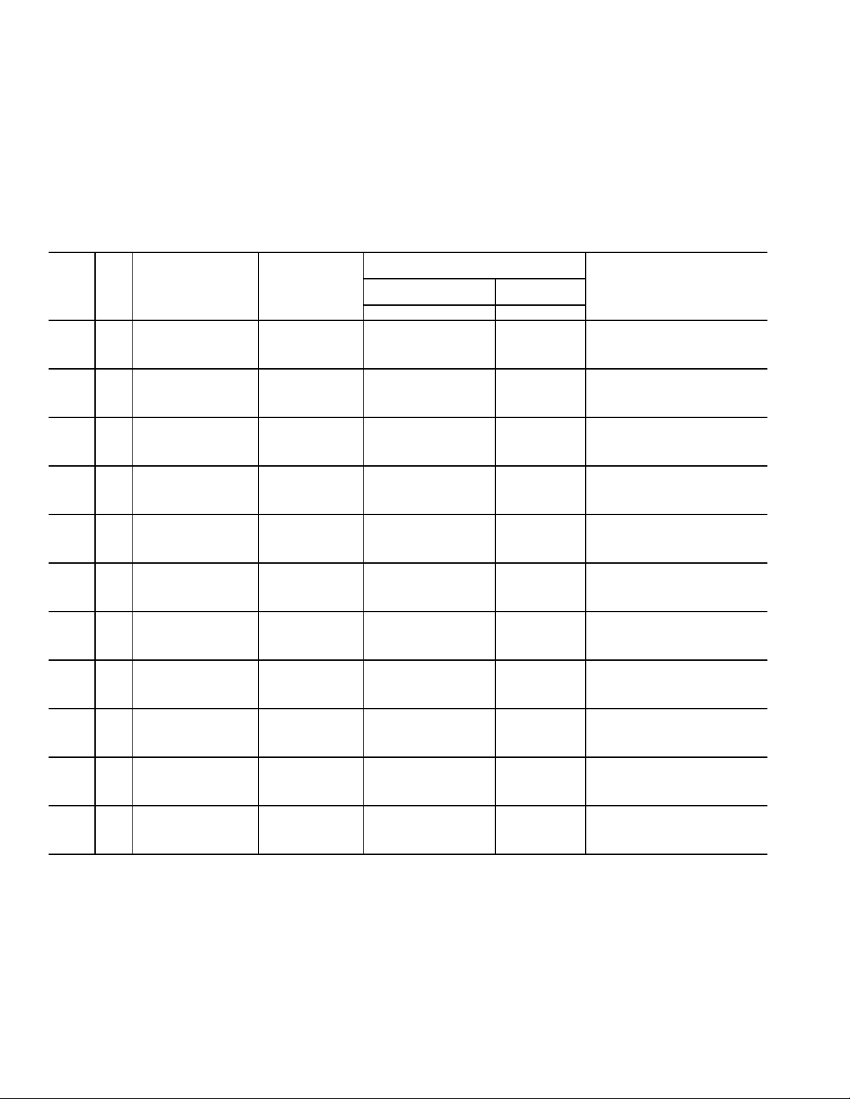
Table 1 — 35L,N Units
UNIT DESCRIPTION
35L Basic unit, no mixing
35N Premium unit, high mixing, constant volume flow sensing
STORAGE AND HANDLING — Inspect for damage upon
receipt. Shipping damage claims should be filed with shipper
at time of delivery. Store in a clean, dry, and covered location.
Do not stack cartons. When unpacking units, care should be
taken that the inlet collars and externally mounted components
do not become damaged. Do not lift units using collars, sensors
or externally mounted components as handles. Do not lay
uncrated units on end or sides. Do not stack uncrated units over
6 ft high. Do not manhandle. Do not handle control boxes by
tubing connections or other external attachments. Table 2
shows component weights.
INITIAL INSPECTION — Once items have been removed
from the carton, check carefully for damage to duct connections, coils or controls. File damage claim immediately with
transportation agency and notify Carrier.
UNIT IDENTIFICATION — Each unit is supplied with a
shipping label and an identification label (Fig. 2).
INSTALLATION PRECAUTION — Check that construction
debris does not enter unit or ductwork. Do not operate the
central-station air-handling fan without final or construction
filters in place. Accumulated dust and construction debris
distributed through the ductwork can adversely affect unit
operation.
SERVICE ACCESS — Provide service clearance for unit
access.
CODES — Install units in compliance with all applicable code
requirements.
ODS: 2181487
TAG:
FACTORY NO: 832889 ITEM: 003
MODEL NO: 35LN 06
MIN
COLD INLET CFM:
MAX
HOT INLET CFM:
HAND (COLD INLET LOC):
CFGCD: 1A*0*0*0R*0606*D000*00*000*0000
0
RC
D000 CTRL BOX E
SIZE: C=06 H=06
VP:
VP:
Fig. 2 — Unit Identification Label
Table 2 — 35L,N Unit Weights
UNIT SIZE
35L
35N
DDC — Direct Digital Controls
NOTE: Data is based on the following conditions:
1. Unit casing is 22 gage.
2. Unit insulation is
fiberglass.
3. Units rated with standard linear flow sensor.
BASE
UNIT
(lb)
4, 5, 6 29 37 47
7, 8 33 41 51
9, 10 41 49 59
12 51 59 69
14 67 75 85
16 75 83 93
22 129 137 147
6 31 39 49
8 42 50 60
10 61 69 79
12 80 88 98
14 98 106 116
16 111 119 129
LEGEND
1
WITH
PNEUMATIC
CONTROLS
(lb)
/2-in. thick, 1.5-lb Tuf-Skin Rx™ dual density
ANALOG CONTROLS
UP
MAX
MIN
.000
.000
.000
.000
WITH DDC OR
(lb)
Fig. 1 — 35L Dual Duct Box
Warranty — All Carrier-furnished items carry the standard
Carrier warranty.
CONTROL ARRANGEMENTS
The 35L,N dual duct units are offered with a wide variety of
factory-mounted controls that regulate the volume of air delivery from the unit and respond to cooling and heating load
requirements of the conditioned space. Stand-alone controls
will fulfill the thermal requirements of a given control space.
These devices are available in both pneumatic and electronic
arrangements. Carrier PIC (Product Integrated Controls) is a
communicating control that is integrated with the building system. The PIC controls are compatible with the CCN system. A
number of DDC (Direct Digital Controls) control packages by
others are available for consignment mounting, as indicated.
Control offerings are:
35(L,N)A: Analog Electronic
35(L,N)C: CCN Direct Digital Electronic
35(L,N)P: Pneumatic
35(L,N)N: None or DDC by others
Each control approach offers a variety of operating functions; a control package number identifies combinations of
control functions. The following listings contain the basic
function arrangements for each control offering. Because of the
2

variety of functions available, circuit diagrams, operating sequences, and function descriptions are contained in separate
Application Data publications. Refer to the specific control
publication for details.
CCN Control Arrangement — The CCN control
packages must be used in combination with a thermostat. Thermostats are not included in the CCN package.
4160: Constant volume dual duct
4170: 35N only, variable volume dual duct, constant minimum
cooling (requires cold deck inlet and total flow probe)
4175: 35N only, variable volume dual duct, cooling close-off
during heating (requires hot deck inlet and total flow probe)
4180: 35N only, constant ventilation dual duct, Cooling only
(requires cold deck inlet and total flow probe)
4190: Variable air volume (VAV) with Demand Control Venti-
lation (DCV) requires separate CO
sensor
2
Analog Electronic Control Arrangement — Con-
trol package is pressure independent and includes a standard
linear airflow sensor in both the hot and cold inlets for variable
air volume control, 24-volt transformer, control enclosures,
and a wall thermostat to match the control type.
Variable volume control:
2400 — Heating and cooling control, hot and cold inlet sensor
location (35L,N)
2440 — Heating and cooling control, hot inlet and discharge
airflow sensing (35N only)
2470 — Heating and cooling control, cold inlet and discharge
airflow sensing (35N only)
Direct Digital Electronic Control Arrangement
(Field Supplied) — Control packages are field supplied
for factory mounting, unless otherwise noted. All DDC control
arrangements include a standard linear inlet flow sensor,
24-volt transformer and control enclosure.
Contact Carrier for details about mounting field-supplied
controls.
Pneumatic Control Arrangement — All control pack-
ages are pressure independent and include standard linear
airflow sensors in both the hot and cold inlets for variable air
volume control or an airflow sensor in one inlet and the unit
discharge for constant volume control arrangements. Thermostats will either be direct acting (DA) or reverse acting (RA),
and damper position will be identified as normally open (NO)
or normally closed (NC).
Variable air volume control with inlet air sensing (all units):
1500 — Multi-function controller, DA-NC cold inlet, NC
hot inlet
1501 — Multi-function controller, DA-NC cold inlet, NO
hot inlet
1502 — Multi-function controller, DA-NO cold inlet, NO
hot inlet
1503 — Multi-function controller, DA-NO cold inlet, NC
hot inlet
1504 — Multi-function controller, RA-NC cold inlet, NC
hot inlet
1505 — Multi-function controller, RA-NC cold inlet, NO
hot inlet
1506 — Multi-function controller, RA-NO cold inlet, NO
hot inlet
1507 — Multi-function controller, RA-NO cold inlet, NC
hot inlet
Constant volume control with hot inlet and discharge air
sensing (35N Units):
1508 — Multi-function controller, DA-NC cold inlet, NC
hot inlet
1509 — Multi-function controller, DA-NC cold inlet, NO
hot inlet
1510 — Multi-function controller, DA-NO cold inlet, NO
hot inlet
1511 — Multi-function controller, DA-NO cold inlet, NC
hot inlet
1512 — Multi-function controller, RA-NC cold inlet, NC
hot inlet
1513 — Multi-function controller, RA-NC cold inlet, NO
hot inlet
1514 — Multi-function controller, RA-NO cold inlet, NO
hot inlet
1515 — Multi-function controller, RA-NO cold inlet, NC
hot inlet
Constant volume control with cold inlet and discharge air
sensing (35N units):
1516 — Multi-function controller, DA-NC cold inlet, NC
hot inlet
1517 — Multi-function controller, DA-NC cold inlet, NO
hot inlet
1518 — Multi-function controller, DA-NO cold inlet, NO
hot inlet
1519 — Multi-function controller, DA-NO cold inlet, NC
hot inlet
1520 — Multi-function controller, RA-NC cold inlet, NC
hot inlet
1521 — Multi-function controller, RA-NC cold inlet, NO
hot inlet
1522 — Multi-function controller, RA-NO cold inlet, NO
hot inlet
1523 — Multi-function controller, RA-NO cold inlet, NC
hot inlet
A multi-function controller is capable of providing DA-NO,
DA-NC, RA-NC or RA-NO functions (all units).
No Control
0000: 35L,N box only
D000: 35L,N box with control box only
D001: 35L,N box with control box and transformer
INSTALLATION
Step 1 — Install Volume Control Box
1. Move unit to installation area. Remove unit from shipping package. Do not handle by controls or damper
extension rod.
2. The unit has factory-installed brackets.
3. Suspend units from building structure with straps, rods,
or hanger wires. Secure the unit and level it in each direction.
Step 2 — Make Duct Connections
1. Install supply ductwork on each of the unit inlet collar.
Check that air-supply duct connections are airtight and
follow all accepted medium-pressure duct installation
procedures. (Refer to Tables 3-5 for pressure data.)
2. Install the discharge ducts. Fully open all balancing
dampers.
A straight length of inlet duct is not required before the unit
inlet. Ninety-degree elbows or tight radius flexible duct immediately upstream of inlet collar should be avoided.
3
Step 3 — Install Sensors and Make Field Wiring
Connections — Electric Analog or DDC (Direct
Digital Controls) —
submittals and control application diagrams for control specifications. All field wiring must comply with National Electrical
Code (NEC) and local requirements. Refer to the wiring diagram
on the unit for specific wiring connections.
INLET
SIZE
(0.09)
(0.14)
(0.20)
(0.27)
(0.35)
(0.44)
(0.55)
(0.78)
(1.07)
(1.40)
(2.63)
*CCN (Carrier Comfort Network®) controls permit a lower minimum
flow.
NOTES:
1. ∆ P
2. To obtain Total Pressure, add the Velocity Pressure for a
CFM
(in.)
4
5
6
7
8
9
1200 0.40 0.32
10
1075 0.20 0.10
1450 0.36 0.17
12
1000 0.08 0.04
1550 0.19 0.09
2100 0.34 0.17
14
1375 0.07 0.04
2125 0.17 0.10
2900 0.31 0.19
16
1775 0.06 0.04
2725 0.14 0.10
3700 0.25 0.17
1200
22
3300 0.07 0.04
5200 0.16 0.09
7000 0.31 0.17
is the difference in static pressure across the assembly,
s
with the damper fully open.
givenCFMtotheStaticPressuredrop(∆ P
configuration.
MINIMUM AIRFLOW
50
110 0.10 0.01
170 0.23 0.02
230 0.43 0.03
75
170 0.09 0.02
265 0.23 0.04
360 0.43 0.08
100
240 0.09 0.04
380 0.22 0.09
520 0.42 0.17
150
330 0.09 0.04
525 0.23 0.09
710 0.41 0.17
200
440 0.09 0.04
675 0.21 0.09
925 0.39 0.17
250
550 0.08 0.07
875 0.21 0.17
300
675 0.08 0.04
450
600
800
Refer to specific unit dimensional
Table 3 — 35L Non-Mixing Dual Duct Basic Pressure Data
(CFM)*
40
or
0
63
or
0
90
or
0
123
or
0
160
or
0
203
or
0
251
or
0
361
or
0
491
or
0
642
or
0
1211
or
0
MINIMUM CCN
AIRFLOW (CFM)
23
or
0
36
or
0
52
or
0
71
or
0
93
or
0
117
or
0
145
or
0
208
or
0
284
or
0
371
or
0
699
or
0
) of the desired
s
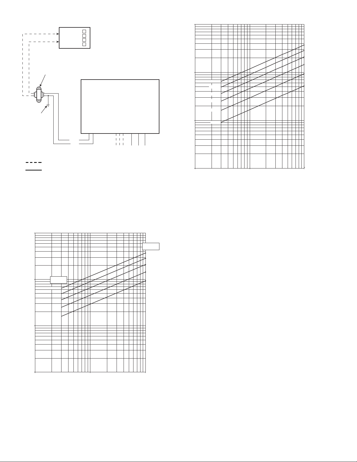
A field-supplied transformer is required if the unit was not
equipped with a factory-installed transformer. See Fig. 3.
NOTE: Refer to wiring diagram attached to each unit for
specific information on that particular unit.
Unit airflow should not be set outside of the range noted in
Fig. 4A-4C and the performance data section of this document.
MINIMUM INLET STATIC PRESSURE
(Unit Pressure Drop) (in. wg)
Veloc it y
Pressure
∆ V
PS
0.02 0.00
0.02 0.00
0.02 0.01
0.02 0.01
0.02 0.01
0.02 0.01
0.02 0.01
0.02 0.01
0.01 0.01
0.01 0.01
0.02 0.01
Basic
Unit
∆ P
S
MINIMUM SYSTEM OPERATING
PRESSURE (in. wg) AT
MAXIMUM LISTED FLOW RATE
0.03
0.08
0.17
0.17
0.18
0.31
0.17
0.17
0.18
0.18
0.17
4
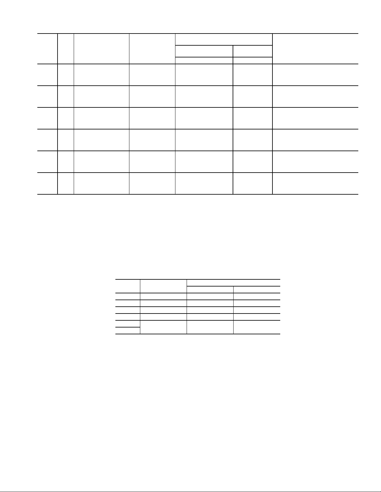
Table 4 — 35N Dual Duct, Full Blending Basic Pressure Data — Inlet Sensor Pickup
MINIMUM INLET STATIC PRESSURE
INLET
SIZE
(Area)
6
(0.20)
8
(0.35)
10
(0.55)
12
(0.78)
14
(1.07)
16
(1.40)
*Assumes inlet flow sensor. For discharge flow sensor, use data for
next even size. CCN (Carrier Comfort Network®) controls permit a
lower minimum flow. Size 16 discharge is same as inlet.
NOTES:
is the difference in static pressure across the assembly,
1. ∆P
s
with the damper fully open.
2. Minimum recommended airflow (cfm) is based on 0.03 in. wg
differential pressure on the inlet sensor or 0 airflow. 0.03 in. wg
is equal to 15-20% of the nominal flow rating of the terminal
MINIMUM AIRFLOW
CFM
100
240 0.06 0.16
380 0.15 0.40
520 0.28 0.72
200
440 0.06 0.15
675 0.14 0.36
925 0.26 0.68
300
675 0.05 0.20
1075 0.14 0.52
1450 0.25 0.94
450
1000 0.04 0.18
1550 0.09 0.44
2100 0.16 0.80
600
1375 0.04 0.23
2125 0.09 0.54
2900 0.17 1.01
800
1775 0.02 0.19
2725 0.04 0.44
3700 0.08 0.81
(CFM)
90
or
0
160
or
0
251
or
0
361
or
0
491
or
0
642
or
0
MINIMUM CCN
AIRFLOW (CFM)
52
or
0
93
or
0
145
or
0
208
or
0
284
or
0
371
or
0
(Unit Pressure Drop) (in. wg)
Velocity
Pressure
∆ V
PS
Basic
Unit
∆ P
0.01 0.03
0.01 0.03
0.01 0.04
0.01 0.04
0.01 0.04
0.00 0.04
unit. Less than 15-20% may result in greater than ±5% control
of the unit airflow. Some DDC controls, supplied by others, may
have different limitations.
3. Minimum airflow may be 0.
4.Maximumairflow(cfm)isbasedona1in.wgdifferential
pressure from the airflow sensor.
5. To obtain Total Pressure, add the Velocity Pressure for a
givenCFMtotheStaticPressuredrop(∆P
configuration.
MINIMUM SYSTEM OPERATING
PRESSURE (in. wg) AT
MAXIMUM LISTED FLOW RATE
S
0.42
0.44
0.43
0.43
0.48
0.48
) of the desired
s
Table 5 — 35N Dual Duct, Full Blending — Discharge Sensor Pickup
INLET
SIZE
MAX. PRIMARY
AIRFLOW (cfm)
6 927 185 or 0 93 or 0
8 1448 290 or 0 145 or 0
10 2085 417 or 0 208 or 0
12 2838 568 or 0 284 or 0
14
16
3706 741 or 0 371 or 0
CCN — Carrier Comfort Network
MINIMUM AIRFLOW
Standard CCN
5
L1
120VAC
208VAC
240VAC
277VAC
CLASS II
TRANSFORMER
(OPTIONAL)
ANALOG OR DDC
CONTROLLER
GROUND
24VAC
BLU
YEL
24 VAC
POWER
LEGEND
DDC — Direct Digital Controls
Field Wiring
Fac to ry Wiring
NOTE: Drawing is typical — refer to actual unit wiring diagram for
details.
Fig. 3 — Wiring of Optional Factory-Mounted
Transformer
10000
1000
16 inch
14 inch
CFM
100
10
12 inch
10 inch
8 inch
6 inch
0.01
FLOW PROBE PRESSURE DIFFERENTIAL IN.WG
VOLTS (ANALOG CONTROLS)
0.1
NOTE: Size 16 discharge is same as inlet.
Fig. 4B — Dual Duct Inlet Flow Probe Chart
(35N only)
3665
2840
2086
1449
927
522
CFM AT ONE INCH SIGNAL
1
10000
1000
CFM
100
10
0.01
Largest
Inlet Size
14-16"
12 "
10 "
8 "
6 "
0.1
FLOW PROBE PRESSURE DIFFERENTIAL IN.WG
VOLTS (ANALOG CONTROLS)
NOTE: Size 16 discharge is same as inlet.
Fig. 4A — Dual Duct Outlet Flow Probe Chart
(35N only)
Flow
Constant
37093709
2840
2086
1449
927
CFM AT ONE INCH SIGNAL
1
CONTROL SET UP
General —
maintain optimum temperatures in the conditioned zone by
varying the air volume supplied by the hot and cold ducts while
providing the proper discharge air temperature.
To balance the unit it is necessary to set both the maximum
and minimum set points of the controllers. Many types of control options are available, each have specific procedures required for balancing the unit.
The 35L,N dual duct terminals are designed to
Set Points — Maximum and minimum airflow set points
are normally specified for the job and specific for each unit on
the job. Where maximum and minimum airflow levels are not
specified on the order, default values are noted on unit ID label.
Field Adjustment of Minimum and Maximum
Airflow Set Points —
probe which measures a differential pressure proportional to
the airflow. The relationship between flow probe pressures and
cfm is shown in the Flow Probe Chart (Fig. 4A-4C). This chart
is attached to each unit.
Each unit is equipped with a flow
System Calibration of the Linear Averaging
Flow Probe —
operation, the velocity sensor and linear averaging flow probe
must be calibrated to the controller. This will ensure that airflow measurements will be accurate for all terminals at system
start-up.
System calibration is accomplished by calculating a flow
coefficient that adjusts the pressure fpm characteristics. The
flow coefficient is determined by dividing the flow for a given
unit (design air volume in cfm), at a pressure of 1.0 in. wg
differential pressure, by the standard pitot tube coefficient of
4005. This ratio is the same for all sizes if the standard linear
averaging probe is used.
Determine the design air velocity by dividing the design air
volume (the flow at 1.0 in. wg) by the nominal inlet area
(sq ft). This factor is the K factor.
To achieve accurate pressure independent
6

10000
8000
6000
4000
2000
1000
800
600
400
CFM
200
100
80
60
40
20
10
0.01 .03
22
SIZE
16
SIZE
14
SIZE
12
SIZE
10
SIZE
9
SIZE
8
SIZE
7
SIZE
SIZE 6
5
SIZE
4
SIZE
.05
FLOW PROBE PRESSURE DIFFERENTIAL IN. WG
0.1
0.3 0.5
7250
3709
2840
2086
1449
1174
927
710
522
362
232
1
NOTE: Size 22 available on 35L units only.
Fig. 4C — Dual Duct Inlet Flow Probe Chart
(35L only)
Carrier inlet areas are shown in Table 6. The design air
volume is shown in this table. It can be determined from this
table that the average design air velocity for those units is equal
to 2656 fpm at 1.0-in. wg.
Table 6 — Inlet Areas
35L,N UNIT SIZE 04* 05* 06 07* 08 09*
INLET
DIAMETER
4.0 5.0 6.0 7.0 8.0 9.0
CFM AT 1 IN. WG 232 362 502 710 927 1174
INLET AREA
(sq ft)
.
0.087 0.136 0.196 0.267 0.349 0.442
35L,NUNITSIZE1012141622*
INLET DIAMETER 10.0 12.0 14.0 16.0 16 x 24
CFM AT 1 IN. WG 1449 2086 2840 3709 7250
INLET AREA
(sq ft)
0.545 0.785 1.069 1.396 2.640
*35L units only.
NOTE: For Carrier ComfortID™ terminals, all flow sizes are normal-
ized using a single Probe Multiplier (PMF) for all sizes equal to
2.273.
PNEUMATIC CONTROLS
All control packages are pressure independent and include
standard linear airflow sensors in both the hot and cold inlets
for variable air volume control (control sequence 1500 to 1507)
or an airflow sensor in one inlet and unit discharge for constant
volume control arrangements (control sequence 1508 to 1523).
Preparation for Balancing
1. Inspect all pneumatic connections to assure tight fit and
proper location.
2. Verify that the thermostat being used is compatible with
the control sequence provided (direct acting or reverse
acting).
3. Check main air pressure at the controller(s). The main air
pressure must be between 15 psi and 25 psi. (If dual or
CFM AT ONE INCH SIGNAL
switched-main air pressure is used, check the pressure at
both high and low settings.) The difference between
“high” pressure main and “low” pressure main should be
at least 4 psi, unless otherwise noted, and the “low” setting difference should exceed 15 psi.
4. Check that the unit damper will fail to the proper position
when main air pressure is lost. Disconnect the pneumatic
actuator line from the velocity controller and observe the
VAV damper position. The damper should fail to either a
normally open position (indicator mark on shaft end is
horizontal) or a normally closed position (indicator mark
on shaft end is vertical).
5. Check that there is primary airflow in the inlet duct.
6. Connect a Magnehelic gage, inclined manometer or other
differential pressure measuring device to the balancing
taps provided in the velocity probe sensor lines. The
manometer should have a full scale reading of 0.0 to
1.0 in. wg. The high pressure signal is delivered from the
front sensor tap (away from the valve), and the low pressure signal is delivered from the back line (near the
valve). The pressure differential between high and low
represents the amplified velocity pressure in the inlet
duct.
7. Read the differential pressure and enter the Flow Probe
Chart to determine the airflow in the terminal unit. This
chartisshowninFig.4A-4Candisalsoattachedtothe
side of each unit. For example, a differential pressure of
0.10 in. wg for a size 8 unit yields an airflow of 275 cfm.
Volume controller for units is shown in Fig. 5.
Balancing Procedure (Control Sequences
1500-1523)
1. Damper action is factory set at NO (normally open), or
NC (normally closed). To reselect loosen damper selection switch screw and align pointer with damper pointer
and tighten screw. The spring range of the actuator is not
critical since the controller will output the necessary pressure to the actuator to position the damper according to
set point. (See Fig. 5.)
2. Pipe the controller: Connect port “B” to the damper actuator. Connect port “M” to the clean, dry main air. Connect
port “T” to the thermostat output. Connect port “H” to the
total pressure tap on the airflow sensor. Connect port “L”
to the static pressure tap on the airflow sensor.
The controller can be set up for cooling or heating applications
using either a direct acting (DA) or reverse acting (RA) thermostat signal. The two flow adjustments are labeled “LO
STAT ∆P” and “HI STAT ∆P. ”
TO THERMOSTAT BRANCH SIGNAL
(RESET SIGNAL)
RESET START POINTADJUSTMENT
(FACTORY SETAT 8 PSI)
* TO STATIC PRESSURE
TO TOTALPRESSURE
*(DIFFERENCE IS: DIFFERENTIAL
PRESSURE, OR DEVICE
VELOCITY PRESSURE)
PUSH ON NIPPLES
FOR 3/16” (5) I.D.
FR TUBING (5)
TO DAMPER
ACTUATOR
TO MAIN AIR
SUPPLY
LOOSEN SCREW TO
CHANGE DAMPER ACTION
(SUPPLIED IN N.O. POSITION)
GAGE TAP. LEAVE CAP ON UNLESS
CONNECTING GAGE FOR RESET
START OR RESET SPAN ADJUSTMENT
DAMPER ACTION SELECTION
(FACTORY SETAT NORMALLY OPEN)
NOTE: SCREW MUST BE TIGHT ANDARROWS
IN PERFECT ALIGNMENT FOR DEVICE TO FUNCTION PROPERLY.
H
B
M
DAMPER
Fig. 5 — CSC-3011 Controller
L
NC
NO
G
T
DIFFERENTIAL PRESSURE (FLOW)
RESETSTART
LO STAT ∆P
I
I
R
N
R
N
C
C
RESETSPAN
LIMIT ADJUSTMENT WHEN T’STAT
PRESSURE IS HIGH (HI STAT)
(FACTORY SETAT 0.65 IN. WG.)†
HISTAT ∆P
†- FIELD ADJUSTMENT REQUIRED
DIFFERENTIAL PRESSURE (FLOW)
LIMIT ADJUSTMENT WHEN T’STAT
PRESSURE IS LOW (LO STAT)
(FACTORY SETAT 0 IN. WG.)†
ALL ADJUSTMENTS CCW TO INCREASE
(1/8”-5/32” FLATBLADE SCREWDRIVER)
RESET SPANADJUSTMENT
(FACTORY SETAT 5 PSI)
7

LO STAT ∆P setting is the desired airflow limit when the
thermostat pressure is less than, or equal to, the reset start
point.
• For DA Cooling or RA Heating:
Adjust LO STAT ∆P to the desired minimum airflow
with 0 psig (or a pressure less than the reset start point) at
port “T.” The LO STAT ∆P must be set first. The LO
STAT ∆P will affect the HI STAT ∆P setting.
• For RA Cooling or DA Heating:
Adjust LO STAT ∆P to the desired maximum airflow
with 0 psig (or a pressure less than the reset start point) at
port “T.” The LO STAT ∆P must be set first. The LO
STAT ∆P will affect the HI STAT ∆P setting.
HI STAT ∆P setting is the desired airflow limit when the ther-
mostat pressure is greater than, or equal to, the reset stop-point.
The reset stop-point is the reset span pressure added to the
reset start-point pressure.
• For DA Cooling or RA Heating (see Fig. 6):
Adjust HI STAT ∆P to the desired maximum airflow with
20 psig (or a pressure greater than the reset stop point) at
port “T.” The HI STAT ∆Pmustbesetlast.TheHISTAT
∆P setting will be affected by the LO STAT ∆P setting.
• For RA Cooling or DA Heating (see Fig. 6):
Adjust HI STAT ∆P to the desired minimum airflow with
20 psig (or a pressure greater than the reset stop point) at
port “T.” The HI STAT ∆Pmustbesetlast.TheHISTAT
∆P setting will be affected by the LO STAT ∆P setting.
NOTE: After the “LO STAT ∆P” and “HI STAT ∆P” initial
adjustments are made, cycle the thermostat pressure a few
times to settle the internal reset mechanisms and verify settings. Fine tune the settings if necessary. The thermostat pressure may be left at a high pressure and the “G” port cap may be
removed and replaced to cycle the reset mechanism.
RESET START setting is factory set at 8.0 psig. This is the
lowest thermostat pressure that the LO STAT ∆P airflow will
begin to reset towards the HI STAT ∆P airflow. To change the
RESET START setting; regulate thermostat pressure to the “T”
port to the desired reset start point pressure, adjust RESET
START adjustment until pressure at the “G” port is slightly
higher than 0 psig, i.e., 0.1 psig.
NOTE: The “G” port taps into the controller’s internal reset
chamber, which always starts at 0 psig. The RESET START
adjustment is a positive bias adjustment that sets the desired
thermostat start point to the controller’s internal reset start
point of 0 psig.
RESET SPAN setting is factory set at 5.0 psig. This is the
required change in thermostat pressure that the controller will
reset between the LO STAT ∆P setting and the HI STAT ∆P
setting. To change the RESET SPAN setting; adjust RESET
SPAN adjustment until pressure at the “G” port equals the
desired reset span pressure.
NOTE: The “G” port taps into the controller’s internal reset
chamber, which will always be at a pressure between 0 psig
and the RESET SPAN pressure.
Preventative Maintenance
1. Inspect pneumatic tubing for loose connections or leaks.
2. Clean out pneumatic line filters regularly according to
manufacturer’s recommendations.
Pneumatic Control Troubleshooting — See Table 7.
DA HEATING
MAX
F
L
O
W
MIN
03813 psig
ROOM TEMPERATURE
MAX
F
L
O
W
MIN
ROOM TEMPERATURE
*May require changing the RESET START from 8.0 to 3.0 psig if
sequencing is involved.
Reset
Span
∆
Reset Start*
RA HEATING
Reset
Span
13 8
∆
Reset Start
3
LO STAT ∆P
HI STAT ∆P
HI STAT ∆P
LO STAT ∆P
0 psig
Fig. 6 — Reset Cycle for CSC-3011 Control
DA COOLING
MAX
F
L
O
W
MIN
03813 psig
ROOM TEMPERATURE
MAX
F
L
O
W
MIN
ROOM TEMPERATURE
Reset
Span
∆
Reset Start
RA COOLING
Reset
Span
8
13
∆
Reset Start*
3
HI STAT ∆P
LO STAT ∆P
LO STAT ∆P
HI STAT ∆P
0 psig
Table 7 — Troubleshooting
PROBLEM PROBABLE CAUSE
Controller does not reset to maximum or minimum set point during balance procedure.
Controller does not reset to maximum or minimum set point during
operation.
Pneumatic actuator does not stroke fully. Leak in pneumatic line between the controller and the actuator. Main air
Air valve stays in wide open position. Velocity probe is blocked by an obstruction (sandwich bag, etc.). Insuffi-
NOTE: Always check:
• Main air pressure (15 psi to 25 psi) at the controller.
• Disconnected or kinked pneumatic lines to the controller.
• Quality of compressed air (oil or water in lines).
Balancer is using the thermostat for control signal. An artificial signal
must be provided in place of the thermostat.
Thermostat is not demanding maximum or minimum air volume. Main
air pressure at the controller is less than 15 psi.
pressure at the controller is less than 15 psi. Leak in the diaphragm.
cient supply air in the inlet duct.
• Proper thermostat signal and logic (Direct/Reverse Acting).
• Blocked velocity probe or insufficient primary supply air.
• Leaks in the actuator diaphragm.
• Mechanical linkage of the actuator/air valve.
8

ANALOG CONTROLS
Balancing Procedures (Control Sequences
2400, 2440, 2470) —
system is a pressure independent volume reset control that uses
KMC Controls CSP-5001 controller-actuator. See Fig. 7.
The system provides for independently adjustable set points
for minimum, maximum, and auxiliary airflow limits.
Room temperature control is provided by the associated
room thermostat which is selected according to the application.
The room thermostat provides a fixed 2 degrees F reset span regardless of the minimum and maximum velocity limit set
points.
Adjustments for the minimum and maximum airflows are
made at the thermostat.
The thermostat (CTE-5100 Series) operates on a 16 vdc
power supply from the CSP controller and outputs a 0 to
10 vdc signal on the T terminals; T
[direct acting]) and T
acting]). See the reference sequence diagram on unit for details
on which ‘T’ terminals are used on each model thermostat, but
in general T
for heating. Terminals T1and T2are adjustable to limit minimum and maximum flow. Terminals T
0 to 10 vdc output signal.
1. Required tools:
a.
b. Smallflatblade(
c. Digital voltmeter capable of displaying a 0 to
d. HSO-5001 Test Leads (optional for meter taps)
2. Remove thermostat cover.
Thermostat cover is removed by loosening the setscrews
on each side of the thermostat. Using a
wrench turn the setscrews clockwise until cover is loose.
3. Check voltages.
Verify 16 vdc between (+) and (–) terminals.
and T3are used for the cooling mode, T2and T
1
1
/16in. hex/key wrench
10 vdc range which will display in hundredths of
vdc
The analog electronic control
in the cooling mode (DA
in the heating mode (RA [reverse
2
1
1
and T4have a fixed
3
/8in.) screwdriver
1
/6in. hex/key
Applications for Dual Duct (Minimum Air From
Cold Duct) —
plished by connecting two CSP-5001 Series controllers with a
dual set point (RA/DA) thermostat, as shown in Fig. 8. In this
application the CSP controllers are mounted separately on the
cold and hot deck dampers with each utilizing its own flow
sensor. The cold deck utilizes the T
while the hot deck controller receives its requested flow signal
from T
maximum flow settings. In addition, by using the “R” override
terminal on the thermostat cold deck, minimum flow can be
overrided to zero upon a call for heating (or vice-versa). See
Fig. 9 and 10.
4
. Both units can be set independently for minimum and
2
Fig. 8 — Dual Control Connections
Dual duct applications are easily accom-
signal from the thermostat
1
∆PPORTS
GEAR
DISENGAGEMENT
BUTTON
0-10V VELOCITY OUTPUT
0-10V INPUT SIGNAL
16V DC OUTPUT
(THERMOSTAT POWER)
Fig. 7 — CSP-5001 Controller
90
45
ADJUSTABLE
END STOPS
0
L
H
N
O
M
MIN
MAX
NOR
METER
M
–
–
16
O
I
24V
U
V
N
DC
AC
I
A
X
˜
– +
%
RED-CLS
M
GRN-OPN
I
N
C
LED
ccw cw
E
HEATING MAX
T2
HEATING MIN
*Connect jumper from T2 to R1 to override cooling minimum to zero, upon
call for heating. Leave R2 connected to ground.
HTG. S.P.
RISE IN ROOM TEMPERATURE
T1
CLG. S.P.
COOLING MAX
COOLING MIN
Fig. 9 — Minimum Air From Cooling
Minimum Air From Heating*
Minimum Air From Cooling*
COOLING MAX
16
DC
V
WIRING
–
INO
U
T
COMMON (16V DC,
INPUT, OUTPUT)
POWER
SUPPLY
–
˜
24 V
AC
HEATING MAX
HEATING MIN
*Connect jumperfromT1toR2tooverrideheatingminimumtozero,upon
call for heating. Leave R1 connected to ground.
T2
HTG. S.P.
RISE IN ROOM TEMPERATURE
CLG. S.P.
T1
COOLING MIN
Fig. 10 — Minimum Air From Heating
9

Analog Control Troubleshooting — The follow-
ing troubleshooting guide is directed towards single duct cooling applications, the same concepts can be applied to other
configurations.
Never jumper terminal 16 VDC to “-” as this would cause
a short, and possibly damage the power supply.
CONTROLLER
1. Verify 24 vac at terminals “~” (phase) and “-” (ground).
Tolerance can be –15% to +20% (20.4 to 28.8 vac).
2. Verify 16 vdc at terminals “16 VDC” and “-”.
a. Tolerance is 15.0 to 17.0 vdc power supply to
thermostat.
b. If not correct, disconnect thermostat and recheck.
If still incorrect, replace CSP controller.
3. Check requested flow voltage on terminal “IN” and “-”.
a. Use charts on pages 6 and 7, Fig. 4A-4C to corre-
late into cubic feet per minute (cfm).
b. If reading is not what is desired, see the System
Calibration of the Linear Averaging Flow Probe
section to adjust thermostat.
4. Check actual flow voltage on terminal “OUT” and “-”
(for 0 to 10 vdc).
Use charts on pages 6 and 7, Fig. 4A-4C to correlate into
cfm.
5. Check box movement, damper rotation, etc.
a. Review requested flow and actual flow parameters
above to determine if unit should be satisfied
(within 50 fpm) or driving open or closed.
b. If damper is not moving, verify damper is not stuck
or at end of travel. Check rotation jumpers for
proper position.
c. Change requested flow to make unit drive opposite
direction. This can be accomplished by moving the
set point sliders or 1) and 2) below.
1.) To manually open the box, remove wiring from
terminal “IN” and jumper terminal “IN” to terminal “16VDC”. This will tell unit to control at
3300 fpm/full airflow, and the green LED
should turn on (and the box should drive open).
2.) To manually close the box, remove wiring from
terminal “IN”, jumper and “IN” terminal to “-”
terminal.Thiswilltellunittocontrolatzero
fpm/no airflow, and the red LED should be on
(and the box should drive closed).
NOTE: When using the same transformer for more than one
control, the phase and ground must be consistent with each
device.
Wire the control as shown on the control package diagram
for the specific installation. Control wiring diagrams can be
found inside the control box.
SUPPLY-AIR TEMPERATURE (SAT) SENSOR INSTALLATION — On terminals with heat, the SAT sensor is provided. The sensor is factory wired to the controlled and shipped in
the control box. The SAT must be field-installed in the duct
downstream from the air terminal. The SAT sensor part number is 33ZCSENSAT. See Table 8 for resistance information.
To install the sensor, proceed as follows:
1. Remove the plug from one of the
7
/8-in. openings in the
control box and pass the sensor probe through the hole.
2. Drill or punch a1/2-in. hole in the duct downstream of
the unit, at a location meeting the requirements shown in
Fig. 11.
3. Using 2 self-drilling screws (supplied), secure the sensor
probe to the duct.
The SAT sensor probe is 6 inches in length. The tip of the
probe must not touch the inside of the duct. Use field-supplied
bushings as spacers when mounting the probe in a duct that is
6 in. or less in diameter.
If the unit is a cooling only unit, the SAT sensor is not provided and is not required.
For units with hot and cold airstreams, locate SAT sensor
probe at least 2 ft downstream (see Fig. 11).
DO NOT run sensor or relay wires in the same conduit or
raceway with Class 1 service wiring.
DO NOT abrade or nick the outer jacket of cable.
DO NOT pull or draw cable with a force that may harm the
physical or electrical properties.
DO NOT bend a cable through a radius sharper than that
recommended by its manufacturer.
AVOID splices in any control wiring.
Perform the following steps if state or local code requires
the use of conduit, or if your installation requires a cable length
of more than 8 ft:
1. Disconnect the sensor cable from the ComfortID zone
controller, at the terminals labeled SAT and GND.
2. Mount the sensor to the duct (see steps 2 and 3 above).
3. Mount a field-supplied 4-in. x 4-in. x 20-in. extension
box over the duct sensor.
1
4. Connect a conduit (
/2-in. nominal) to the zone controller
enclosure and extension box.
5. Pass the sensor probe through the extension box opening
and into the conduit.
6. Reconnect the sensor leads to the zone controller labeled
SAT and GND.
ComfortID™ CONTROLS
Install Sensors and Make Field Wiring
Connections
GENERAL — All field wiring must comply with National
Electrical Code (NEC) and local requirements. Refer to
Tables 8-11 for electrical and wiring specifications.
For information on how to test and balance CCN controls,
refer to the 33ZC Installation and Operation Instructions.
Disconnect electrical power before wiring inside the controller. Electrical shock, personal injury, or damage to the
zone controller can result.
HEATED
AIR
COOL
AIR
LEGEND
SAT — Supply Air Temperature Sensor
ZC — Zone Controller
ZC
Fig. 11 — Supply Air Temperature Probe
(Part No. 33ZCSENSAT) Locations
10
2 FT. MIN.
SAT
LEAVING
AIR

Table 8 — Thermistor Resistance vs Temperature Values for
Supply-Air Temperature Sensor, Primary Air Temperature Sensor and Space Temperature Sensor
RESISTANCE
(Ohms)
29481 32 17050 54 10227 76 6340 98 4051 120
28732 33 16646 55 10000 77 6209 99 3972 121
28005 34 16253 56 9779 78 6080 100 3895 122
27298 35 15870 57 9563 79 5954 101 3819 123
26611 36 15497 58 9353 80 5832 102 3745 124
25943 37 15134 59 9148 81 5712 103 3673 125
25295 38 14780 60 8948 82 5595 104 3603 126
24664 39 14436 61 8754 83 5481 105 3533 127
24051 40 14101 62 8563 84 5369 106 3466 128
23456 41 13775 63 8378 85 5260 107 3400 129
22877 42 13457 64 8197 86 5154 108 3335 130
22313 43 13148 65 8021 87 5050 109 3272 131
21766 44 12846 66 7849 88 4948 110 3210 132
21234 45 12553 67 7681 89 4849 111 3150 133
20716 46 12267 68 7517 90 4752 112 3090 134
20212 47 11988 69 7357 91 4657 113 3033 135
19722 48 11717 70 7201 92 4564 114 2976 136
19246 49 11452 71 7049 93 4474 115 2920 137
18782 50 11194 72 6900 94 4385 116 2866 138
18332 51 10943 73 6755 95 4299 117 2813 139
17893 52 10698 74 6613 96 4214 118 2761 140
17466 53 10459 75 6475 97 4132 119
SPACE TEMPERATURE SENSOR INSTALLATION AND
WIRING — The SPT sensor accessory is ordered separately
for field installation. It is installed on interior walls to measure
room space air temperature. See Fig. 12-16 and Table 8.
The wall plate accommodates both the NEMA (National
Electrical Manufacturing Association) standard and the Euro-
1
/4DIN standard. The use of a junction box to accommo-
pean
date the wiring is recommended for installation. The sensor
may be mounted directly on the wall, if acceptable by local
codes.
DO NOT mount the sensor in drafty areas such as near heating or air-conditioning ducts, open windows, fans, or over heat
sources such as baseboard heaters or radiators. Sensors mounted in those areas will produce inaccurate readings.
Avoid corner locations. Allow at least 3 ft between the sensor and any corner. Air in corners tends to be stagnant resulting
in inaccurate sensor readings.
Sensor should be mounted approximately 5 ft up from the
floor, in an area that best represents the average temperature
found in the space (zone).
The space temperature sensor cover includes a service jack
connector. If wiring connection is made to the service jack, the
connector can then be used to connect a network service tool
with the Carrier Comfort Network® system.
Before installing the space temperature sensor, decide
whether or not the service jack wiring connection will be made.
If connection is desired, the CCN communication cable should
be available at time of sensor installation, for convenient wiring connections. The cable selected must meet the requirements for the entire network. See page 15 for CCN communication cable specifications.
Install and wire the space temperature sensor as follows:
NOTE: Space temperature sensor will be identified as T55 or
T56. Refer to Control Sequence drawings to determine which
SPT is part of the particular control package being installed.
(The difference between T55 and T56 is that T56 includes set
point adjustment capability.)
1. Locate the two Allen type screws at the bottom of the
sensor.
2. Turn the two screws clockwise to release the cover from
the sensor wall mounting plate.
3. Lift the cover from the bottom and then release it from
the top fasteners.
TEMP
(F)
RESISTANCE
(Ohms)
TEMP
(F)
RESISTANCE
(Ohms)
TEMP
(F)
RESISTANCE
(Ohms)
TEMP
(F)
RESISTANCE
(Ohms)
5. Usingtwono.6-32x1mounting screws (provided with
the sensor), secure the sensor to the electrical box.
6. Use 20 gage wire to connect the sensor to the controller.
This size is suitable for distances of up to 500 ft. Use a
three-conductor shielded cable for the sensor and set
point adjustment connections. The standard CCN communication cable may be used. If the set point adjustment
(slide-bar) is not required, then an unshielded, 18 or 20
gage, two-conductor, twisted pair cable may be used. Refer to Table 9.
The CCN network service jack requires a separate,
shielded CCN communication cable. Always use separate cables for CCN communication and sensor wiring.
(Refer to Fig. 15 and 16 for wire terminations.)
7. Replace the cover by inserting the cover at the top of the
mounting plate first, then swing the cover down over the
lower portion. Rotate the two Allen head screws counterclockwise until the cover is secured to the mounting plate
and locked in position.
8. For more sensor information, see Table 8 for thermistor
resistance vs temperature values.
NOTE: Clean sensor with damp cloth only. Do not use
solvents.
Table 9 — Recommended Sensor and Device
Wiring
MANUFACTURER
Belden 8205 88442
Columbia D6451 —
American A21501 A48301
Quabik 6130 —
Alpha 1895 —
Manhattan M13402 M64430
NOTE: Wiring is 20 gage, 2 conductor twisted cable.
PART NUMBER
Regular Plenum
WIRING THE SPACE TEMPERATURE SENSOR AND
SET POINT ADJUSTMENT SLIDEBAR — To wire the sensor and slidebar, perform the following (see Fig. 15 and 16):
1. Identify which cable is for the sensor wiring.
2. Strip back the jacket from the cables for at least 3 inches.
1
Strip
/4-in. of insulation from each conductor. Cut the
shield and drain wire from the sensor end of the cable.
4. Feed the wires from the electrical box through the opening in the center of the sensor mounting plate.
TEMP
(F)
11

3’ (MIN)
OR
2/3 OF WALL HEIGHT
D
5’
2
3
45
61
RED(+)
WHT(GND)
BLK(-)
CCN COM
Fig. 12 — Typical Space Temperature Sensor
Room Location
Cool
Warm
Fig. 13 — Space Temperature Sensor
(P/N 33ZCT56SPT Shown)
SEN
SW1
BLK (GND)
RED (SPT)
SENSOR WIRING
Fig. 15 — Space Temperature Sensor Wiring
(33ZCT55SPT)
2
3
45
61
RED(+)
WHT(GND)
BLK(-)
CCN COM
NOTE: Dimensions are in inches.
Fig. 14 — Space Temperature Sensor and Wall
Mounted Humidity Sensor Mounting
12
SET
SEN
SW1
WHT
(T56)
BLK (GND)
RED (SPT)
SENSOR WIRING
JUMPER
TERMINALS
AS SHOWN
Cool Warm
Fig. 16 — Space Temperature Sensor Wiring
(33ZCT56SPT)

3. Connect the sensor cable as follows:
a. Connect one wire from the cable (RED) to the SPT
terminal on the controller. Connect the other end of
the wire to the left terminal on the SEN terminal
block of the sensor.
b. Connect another wire from the cable (BLACK) to
the ground terminal on the controller. Connect the
other end of the wire to the remaining open terminal on the SEN terminal block.
c. For T56 sensors, connect the remaining wire
(WHITE/CLR) to the T56 terminal on the controller. Connect the other end of the wire to the right
most terminal on the SET terminal block.
d. In the control box, connect the cable shield to
J1-3, equipment ground.
e. Install a jumper between the two center T56 termi-
nals (right SEN and left SET).
WIRING THE CCN NETWORK COMMUNICATION
SERVICE JACK — To wire the service jack, perform the
following:
1. Strip back the jacket from the CCN communication ca-
ble(s) for at least 3 inches. Strip
1
/4in. of insulation from
each conductor. Remove the shield and separate the drain
wire from the cable. Twist together all the shield drain
wires and fasten them together using an closed end crimp
lug or a wire nut. Tape off any exposed bare wire to prevent shorting.
2. Connect the CCN + signal wire(s) (RED) to Terminal 5.
3. Connect the CCN– signal wire(s) (BLACK) to Terminal 2.
4. Connect the CCN GND signal wire(s) (WHITE/CLR) to
Terminal 4 .
PRIMARY AIR TEMPERATURE SENSOR INSTALLATION — A primary air temperature (PAT) sensor is used on a
zone controller which is functioning as a Linkage Coordinator
for a non-CCN (Carrier Comfort Network®)/Linkage compatible air source. The part number is 33ZCSENPAT. See Fig. 17.
The sensor is also available as field-supplied accessory.
When used on a zone controller, try to select a zone controller which will allow installation of the PAT sensor in the main
trunk, as close to the air source as possible. See Fig. 18.
To mount the PAT sensor, remove sensor cover.
1. Drill a
1
/2-in. hole in supply duct.
2. Using field-supplied drill tap screw, secure sensor to duct.
3. Connect sensor to zone controller using field-supplied
2-conductor cable. Refer to Table 9.
4. Use field-supplied wire nuts to connect cable to sensor.
5. At zone controller, connect sensor wires to PAT and GND
terminals.
INDOOR-AIR QUALITY SENSOR INSTALLATION —
The indoor-air quality (IAQ) sensor accessory monitors carbon
dioxide levels. This information is used to increase the airflow
to the zone and may also modify the position of the outdoor-air
dampers to admit more outdoor air as required to provide the
desired ventilation rate. The wall sensor is used to monitor the
conditioned space. The sensor uses infrared technology to
measure the levels of CO
available with or without an LCD readout to display the CO
present in the air. The wall sensor is
2
level in ppm and is also available in a combination model
whichsensesbothtemperatureandCO
The CO
sensors are factory set for a range of 0 to
2
level.
2
2000 ppm and a linear voltage output of 0 to 10 vdc. Refer to
the instructions supplied with the CO
quirements and terminal locations. The sensor requires a sepa-
sensor for electrical re-
2
rate field-supplied 24 vac 25 va transformer to provide power
to the sensor. The transformer may be mounted in the control
box if space is provided (except electric heat units).
Fig. 17 — Primary Air Temperature Sensor
(Part Number 33ZCSENPAT)
Fig. 18 — Primary Air Temperature
Sensor Installation
(Air-Handling Unit Discharge Locations)
For factory configuration changes to some models of the
sensor, the User Interface Program (UIP) or Sensor Calibration
Service Kit is required.
To accurately monitor the quality of the air in the conditioned air space, locate the sensor near the return air grille so it
senses the concentration of CO
leaving the space. The sensor
2
should be mounted in a location to avoid direct breath contact.
Do not mount the space sensor in drafty areas such as near
supply diffusers, open window, fans, or over heat sources. Al-
2
low at least 3 ft between the sensor and any corner. Avoid
mounting the sensor where it is influenced by the supply air;
the sensor gives inaccurate readings if the supply air is blown
directly onto the sensor.
To mount the sensor, refer to the installation instructions
shipped with the accessory kit.
INDOOR AIR QUALITY SENSOR WIRING — To wire the
sensor after it is mounted in the conditioned air space, see
Fig. 19-21 and the instructions shipped with the sensor. Use
13

two 2-conductor 20 AWG twisted-pair cables (see Table 9) to
connect the field-supplied separate isolated 24 vac power
source to the sensor and to connect the sensor to the control
terminals. To connect the sensor to the control, identify the
positive (+) and ground (GND) terminals on the sensor and
connect the positive terminal to the RH/IAQ terminal on the
control and connect the ground terminal to terminal GND.
HUMIDITY SENSOR (Wall-Mounted) INSTALLATION — The accessory space humidity sensor is field supplied and installed on an interior wall to measure the relative
humidity of the air within the occupied space. See Fig. 22.
Theuseofastandard2x4-in.electricalboxtoaccommodate the wiring is recommended for installation. The sensor can
be mounted directly on the wall, if acceptable by local codes.
If the sensor is installed directly on a wall surface, install the
humidity sensor using 2 screws and 2 hollow wall anchors
(field-supplied); do not overtighten screws.
Fig. 19 — Indoor Air Quality Sensor
(Wall-Mounted Version Shown) 33ZCSENCO2
Fig. 20 — Ventilation Rates Based on
CO2Set Point
0
HF23BJ042
Made in Switzerland
by Belimo Automation
LR 92800
NEMA2
LISTED
94D5
U
TEMP.IND. &
L
REG.EQUIP.
Class 2 Supply
WIP
yel
35 in-lb (4 Nm)
80...110s
24VAC/DC
50/60Hz
3VA 2W
5K
COM
2
1
ora
blu
red
blk
1
3
wht
Do NOT clean or touch the sensing element with chemical
solvents; they can permanently damage the sensor.
The sensor must be mounted vertically on the wall. The
Carrier logo should be oriented correctly when the sensor is
properly mounted.
DO NOT mount the sensor in drafty areas such as near heating or air-conditioning ducts, open windows, fans, or over heat
sources such as baseboard heaters, radiators, or wall-mounted
light dimmers. Sensors mounted in those areas will produce
inaccurate readings.
Avoid corner locations. Allow at least 4 ft between the sensor and any corner. Airflow near corners tends to be reduced,
resulting in erratic sensor readings.
Sensor should be vertically mounted approximately 5 ft up
from the floor, beside the space temperature sensor.
For distances up to 500 feet, use a 3-conductor, 18 or
20 AWG cable. A CCN communication cable can be used,
although the shield is not required. The shield must be removed
from both ends of the cable if this cable is used.
IAQ
GND
21
87
24VAC
LINE VOLTAGE
SEPARATE
POWER
SUPPLY
REQUIRED*
*Do not connect to the same transformer that supplies power to the zone controller.
Fig. 21 — Indoor Air Quality Sensor Wiring
14

Fig. 22 — Wall Mounted Relative Humidity Sensor
(P/N 33AMSENRHS000)
The power for the sensor is provided by the control board.
The board provides 24 vdc for the sensor. No additional power
source is required.
To wire the sensor, perform the following:
1. At the sensor, remove 4-in. of jacket from the cable. Strip
1
/4-in. of insulation from each conductor. Route the cable
through the wire clearance opening in the center of the
sensor. See Fig. 23.
2. Connect the RED wire to the sensor screw terminal
marked (+).
3. Install one lead from the resistor (supplied with the sensor) and the WHITE wire, into the sensor screw terminal
marked (–). After tightening the screw terminal, test the
connection by pulling gently on the resistor lead.
4. Connect the remaining lead from the resistor to the
BLACK wire and secure using a field-supplied closed
end type crimp connector or wire nut.
5. Using electrical tape, insulate any exposed resistor lead to
prevent shorting.
6. At the control box, remove the jacket from the cable.
7. Strip
1
/4-in. of insulation from each conductor.
8. Connect the RED wire to terminal +24v on the control
board.
9. Connect the BLACK wire to terminal GND on the control board.
10. Connect the WHITE/CLEAR wire to terminal RH/IAQ
on the control board.
Connect the CCN Communication Bus — The
zone controllers connect to the bus in a daisy chain arrangement. The zone controller may be installed on a primary CCN
bus or on a secondary bus from the primary CCN bus.
Connecting to a secondary bus is recommended.
At 9,600 baud, the number of controllers is limited to
128 zones maximum, with a limit of 8 systems (Linkage
Coordinator configured for at least 2 zones.) Bus length may
not exceed 4000 ft, with no more than 60 devices on any
1000-ft section. Optically isolated RS-485 repeaters are
required every 1000 ft.
At 19,200 and 38,400 baud, the number of controllers
is limited to 128 maximum, with no limit on the number of
Linkage Coordinators. Bus length may not exceed 1000 ft.
The first zone controller in a network connects directly to
the bridge and the others are wired sequentially in a daisy chain
fashion.
The CCN communication bus also connects to the zone
controller space temperature sensor. Refer to Step 3 of the installation section for sensor wiring instructions.
COMMUNICATION BUS WIRE SPECIFICATIONS —
The Carrier Comfort Network (CCN) Communication Bus
wiring is field-supplied and field-installed. It consists of
shielded three-conductor cable with drain (ground) wire. The
cable selected must be identical to the CCN communication
bus wire used for the entire network. See Table 10 for recommended cable.
Table 10 — Recommended Cables
MANUFACTURER CABLE PART NO.
Alpha 2413 or 5463
American A22503
Belden 8772
Columbia 02525
NOTE: Conductors and drain wire must be at least 20 AWG
(American Wire Gage), stranded, and tinned copper. Individual conductors must be insulated with PVC, PVC/nylon, vinyl, Teflon, or
polyethylene. An aluminum/polyester 100% foil shield and an outer
jacket of PVC, PVC/nylon, chrome vinyl, or Teflon with a minimum
operating temperature range of –20 Cto60 C is required.
CONNECTION TO THE COMMUNICATION BUS
1. Strip the ends of the red, white, and black conductors
of the communication bus cable.
2. Connect one end of the communication bus cable to
the bridge communication port labeled COMM2 (if
connecting on a secondary bus).
When connecting the communication bus cable, a
color code system for the entire network is recommended to simplify installation and checkout. See
Table 11 for the recommended color code.
3. Refer to Fig. 23. Connect the other end of the communication bus cable to the terminal block labeled CCN in the
zone controller of the first air terminal. Following the color code in Table 11, connect the Red (+) wire to Terminal
1. Connect the White (ground) wire to Terminal 2. Connect the Black (–) wire to Terminal 3.
4. Connect additional zone controllers in a daisy chain
fashion, following the color coded wiring scheme in
Table 11.
Table 11 — Color Code Recommendations
SIGNAL TYPE
+ Red 1
Ground White 2
– Black 3
CCN BUS WIRE
COLOR
PLUG PIN
NUMBER
NOTE: The communication bus drain wires (shield) must
be tied together at each zone controller. If the communication bus is entirely within one building, the resulting continuous shield must be connected to ground at only one single
point. If the communication bus cable exits from one building and enters another building, connect the shields to
ground at a lightning suppressor in each building where the
cable enters or exits (one point only).
15

HUMIDITY SENSOR
0
HF23BJ042
Made in Switzerland
by Belimo Automation
LR 92800
NEMA 2
LISTED
94D5
TENP IND &
REG. EQUIP.
Class 2 Supply
WIP
yel
RED
WHITE
BLACK
Shield
(If Used)
FAN A C
SEC DMP
HEAT2
FAN
24VAC
N/A
HEAT3
CW
COM
CCW
6
15
RH/IAQ
SECFLOW
J4
DMPPOS
1
1
CCN
J2A
3
1
LOW
1
ZONE Controller
Part Number: 33ZCFANTRM
S/N:
Bus#:
Element#:
Unit#:
HIGH
2
red wht
®
3
35 in-lb (4 Nm)
80...110s
24VAC/DC
50/60 Hz
3VA 2W
5K
COM
1
ora
blk
blu
US
C
1
J6
2
1
J7
3
®
1
J8
3
J6
1
CCW
COMCWHEAT1
24VAC
GND
+10V
GND
TEST
GND
3
16
+24V
SPT
GND
SAT
T56
GND
PAT
N/A
2
1
+
LEN
+
G
G
-
J2B
-
3
J3
SRVC
+
-
J1
24VAC
G
499
CCN
COMMUNICATION
CONNECTOR
BLACK (–)
+
-
RED (+)
WHITE (GND)
CCN
Fig. 23 — Zone Controller Connections
ComfortID™ Controls Start-Up
GENERAL — Air volume delivery to the conditioned space
is controlled by the modulating of the primary air damper and
the sequencing of the air source supply fan. The controller positions the damper by way of an actuator and turns the fan on
and off through linkage for the CCN compatible air source
equipment control.
PRIMARY SYSTEM CHECK
1. Check that all controls, control box, and ductwork have
been properly installed and set according to installation
instructions and job requirements.
2. Check that final filters have been installed in the airhandling apparatus. Dust and debris can adversely affect
system operation.
3. Check fan and system controls for proper operation.
4. Check electrical system connections.
5. Check that all air duct connections are tight.
6. See that all balancing dampers at box outlets are in fullopen position.
ComfortID CONTROL SYSTEM CHECK
1. Check interconnections between thermostats and unit
controls.
2. Force all dampers to control to the maximum cooling cfm
using the Building Supervisor, ComfortWORKS
Network Service Tool or ComfortID Test and Balance
Tool software.
3. Set supply-duct balancing dampers, if used, in maximum
cool position.
4. Check that the static pressure available at each box is
above the minimum required, force all dampers to control
to the minimum cooling cfm and verify that the static
pressure is below the maximum safe operating limits
when the damper is providing minimum cooling airflow.
5. Set air source supply fan speed and duct static pressure
regulator to obtain satisfactory static pressure at design
airflow.
6. While at peak system load, check system operation and
pressures.
7. Check duct pressure at various points in the system. If system static pressure probe has been properly located, pressure atlast units of all branchheaders should remain essentially the same. If pressure has changed considerably, recheck the supply air static pressure controller or relocate
the probe to better sense system pressure changes.
8. Remove all forces and balance each control box zone
using through the balancing procedure described on
page 9.
®
,
16

CCN System Start-Up — The Building Supervisor,
ComfortWORKS®, and the Network Service Tool can aid in
system start-up and troubleshooting.
All set-up and set point configurations are factory set and
field adjustable. Changes are made by using either Building
Supervisor, ComfortWORKS or the Network Service Tool.
TheNetworkServiceToolcanbeusedasaportabledeviceto
change system set-up and set points from a zone sensor or terminal control module. During start-up, the Building Supervisor
ortheNetworkServiceToolcanalsobeusedtoverifycommunication with each controller.
For specific operating instructions, refer to the appropriate
user manual.
COMFORTID TEST AND BALANCE TOOL SOFTWARE — The ComfortID Test and Balance Tool software is
used for testing each controller if the Network Service Tool or
CCN are not available. The ComfortID Test and Balance Tool
is compatible with Windows95 and higher and Windows NT4
(with Service Pack Level 3 or better) operating systems.
This software is used for control calibration. It allows for
various functions that expedite system checks and testing.
Carrier requires the use of the B&B485CARLP9A Port
Powered RS232 to RS485 Converter for proper operation.
NOTE: The B&B485CARLP9A Port Powered RS232 to
RS485 Converter is available through:
B&B Electronics
1500 Boyce Memorial Drive
P.O. Box 1040
Ottawa, IL 61350
Refer to the ComfortID Test and Balance Tool Software Installation and Operation Instructions for additional information.
COMFORTID CONSTANT VOLUME DUAL DUCT
CONTROL PACKAGE NO. 4160 — Dual duct units are
designed to provide accurate temperature control while maintaining a constant airflow to the space. A typical application is
shown in Fig. 24. Use package no. 4160 with 35L,N units.
COMFORTID VARIABLE AIR VOLUME DUAL DUCT
WITH CONSTANT MINIMUM COLD DECK AIRFLOW
CONTROL PACKAGE NO. 4170 — Dual duct units are
designed to provide accurate variable air volume (VAV) temperature control in both heating and cooling modes with a minimum amount of energy consumption. Typically system used
with this control package provide all the ventilation air though
the cold deck only. This control package provides VAV cooling
operation and VAV heating with variable air temperature. The
control will maintain the minimum cooling airflow set point
during heating to provide the required ventilation to the space.
A typical application is shown in Fig. 25. Use package
no. 4170 with 35N units.
COMFORTID VARIABLE AIR VOLUME DUAL DUCT
WITH COLD DECK CLOSE-OFF CONTROL PACKAGE
NO. 4175 — Dual duct units are designed to provide accurate
variable air volume (VAV) temperature control in both heating
and cooling modes with a minimum amount of energy
consumption. A typical system used with this control package
provides ventilation air though both the hot and cold decks.
This control package provides VAV cooling operation and
variable air temperature heating. It will reduce the cold deck
(cooling) airflow to zero during maximum heating to eliminate
energy waste. A typical application is shown in Fig. 26. Use
package No. 4175 with 35N units.
HEAT
ACTUATOR
DAMPER
ACTUATOR
HEATED AIR
LEAVING
AIR
COOL AIR
DAMPER
ACTUATOR
24 VAC
SUPPLY
AIR SENSOR
SLAVE
CONTROLLER
DAMPER
ACTUATOR
HEATED AIR
LEAVING
COOL AIR
DAMPER
ACTUATOR
ZONE
CONTROLLER
24 VAC
CCN BUS
OPTIONAL
SUPPLY
AIR SENSOR
SPACE
TEMPERATURE
SENSOR
Fig. 24 — Constant Volume Dual Duct Control
AIR
ZONE
CONTROLLER
SPACE
CCN BUS
TEMPERATURE
SENSOR
Fig. 25 — VAV Dual Duct with Constant Minimum
Cold Deck Airflow Control
17

HEAT
ACTUATOR
DAMPER
ACTUATOR
HEATED AIR
Leaving
SPACE
SENSOR
Air
Supply
Air Sensor
COOL AIR
DAMPER
ACTUATOR
ZONE
CONTROLLER
CCN BUS
24 VAC
TEMPERATURE
Fig. 26 — VAV Dual Duct with Cold Deck Close-Off
Control
COMFORTID VARIABLE AIR VOLUME DUAL DUCT
WITH CONSTANT VENTILATION CONTROL PACKAGE NO. 4180 — Dual duct units are designed to provide
accurate variable air volume (VAV) temperature control with a
minimum amount of energy consumption. A typical system
used with this control package provides all the ventilation air
though a separate outside air system. The ventilation air is conditioned (heated/cooled/dehumidified) as required to provide a
neutral temperature. The ventilation air is connected to the hot
deck inlet of the terminal. The control package provides VAV
cooling operation and constant volume ventilation. It will
maintain the ventilation airflow set point at all times to provide
the required ventilation to the space. Field supplied and
installed perimeter or ducted heating may additionally be controlled. A typical application is shown in Fig. 27. Use package
no. 4180 with 35N units.
COMFORTID VARIABLE AIR VOLUME DUAL DUCT
WITH DEMAND CONTROLLED VENTILATION CONTROL PACKAGE NO. 4190 — Dual duct units are designed
to provide accurate variable air volume (VAV) temperature
control with a minimum amount of energy consumption. A
typical system used with this control package provides all the
ventilation air though a separate outside air system. The ventilation air is conditioned (heated/cooled/dehumidified) as
required to provide a neutral temperature. The ventilation air is
connected to the hot deck inlet of the terminal. The control
package provides VAV cooling operation and demand controlled ventilation. It will adjust the ventilation to maintain the
required ventilation rate when occupied and maintain at least
the minimum base ventilation rate at all times. Field supplied
and installed perimeter or ducted heating may additionally be
controlled. A typical application is shown in Fig. 28. Use package no. 4190 with 35L,N units.
CCN BUS
SECONDARY
VENTILATION
AIR
CONDITIONED
AIR
CONTROLLER
DAMPER
ACTUATOR
DAMPER
ACTUATOR
ZONE
CONTROLLER
24 VAC
CCN BUS
SPACE
CARBON DIOXIDE
SENSOR
Leaving
SPACE
TEMPERATURE
SENSOR
Optional space or
ducted heat source
Air
Optional supply air
sensor for ducted
heat source
Fig. 28 — VAV Dual Duct with Demand Controlled
Ventilation
SECONDARY
CONTROLLER
DAMPER
VENTILATION
AIR
CONDITIONED
AIR
ACTUATOR
DAMPER
ACTUATOR
ZONE
CONTROLLER
CCN BUS
24 VAC
SPACE
TEMPERATURE
SENSOR
Leaving
Optional space or
ducted heat source
Air
Optional supply air
sensor for ducted
heat source
Fig. 27 — VAV Dual Duct with Constant Ventilation
Control
18


Copyright 2006 Carrier Corporation
Manufacturer reserves the right to discontinue, or change at any time, specifications or designs without notice and without incurring obligations.
Book 3
Ta b 6 a
Catalog No. 04-53350001-01 Printed in U.S.A. Form 35L,N-1SI Pg 20 3-06 Replaces: 35L,M,N-1SI
 Loading...