

Page 1
33MC--URC
Room Controller
40KMC
40KMQ
40QNC
40QNQ
INSTALLATION MANUAL
Page 2
This control system only operates with indoor units of the following types:
40KMC, 40KMQ Cassette, 40QNC, 40QNQ High Wall
For insta lla tio n instructions o f th is u n it, refer to the releva n t manuals.
CONTENTS PAGE
General information 2...............................................................................
Characteristics 2.....................................................................................
Choosing the installation site 2........................................................................
“Room Controller” wired control 3....................................................................
Electrical connections to indoor unit 4.................................................................
Unit configuration 4, 6...............................................................................
Troubleshooting 6...................................................................................
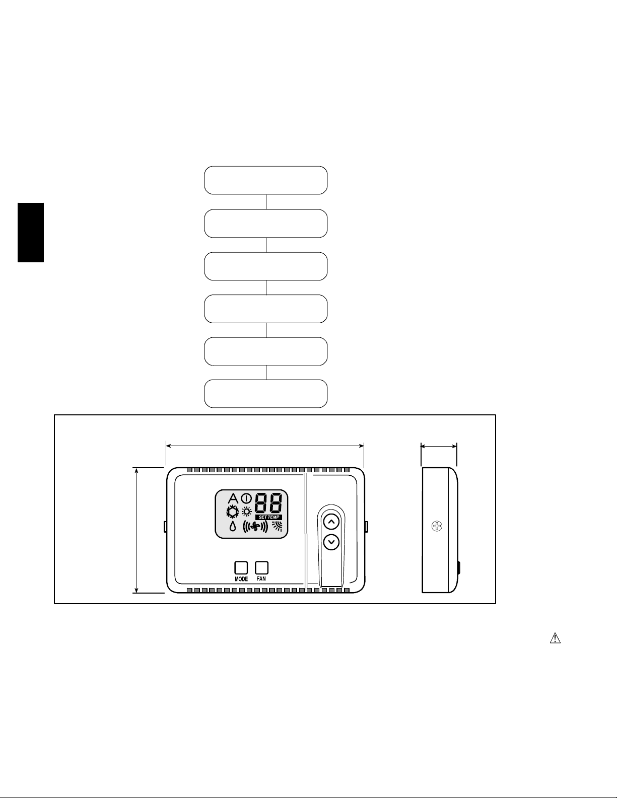
INSTALL AT I O N FL O W CHART
Read manual
Install
Room Controller
33MC--URC
Dimensions (mm)
Wire Room Cont roller
and unit networ k
Configure
Room Controller
Test System
Operate
Room Controller
4--1/4”(108)
3/4”(20)
2--3/14”(70)
SAFETY CONSIDERATIONS
Improper installation, adjustment, alteration, service, maintenance,
or use can cause explosion, fire, electrical shock, or other
conditions which may cause death, personal injury, or property
damage. Consult a qualified installer, service agency, or your
distributor or branch for information or assistance. The qualified
installer or agency must use factory--authorized kits or accessories
when modifying this product. Refer to the individual instructions
packaged with the kits or accessories when installing.
Follow all safety codes. Wear safety glasses, protective clothing,
and work gloves. Use quenching cloth for brazing operations.
Have fire extinguisher available. Read these instructions
thoroughly and follow all warnings or cautions included in
literature and attached to the unit. Consult local building codes and
National Electrical Code (NEC) for special requirements.
Recognize safety information. This is the safety--alert symbol
When you see this symbol on the unit and in instructions or
manuals, be alert to the potential for personal injury. Understand
these signal words; DANGER, WARNING, and CAUTION. These
words are used with the safety--alert symbol. DANGER identifies
the most serious hazards which will result in severe personal injury
or death. WARNING sign ifies hazard s wh ich co u ld result in
personal injury or death. CAUTION is u sed to identify unsafe
practices which would result in minor personal injury or product
and property damage. NOTE is used to highlight suggestions
which will result in enhanced installation, reliability, or operation.
2
Page 3
G
enera
l
inf
C
h
l
lati
d
I
l
lati
ormation andcharacteristics
IMPORTANT: Read the entire instruction manual before
starting the installation.
S For trouble--free installation, which should be carried out
by a qualified installer, follow the installation chart
sequence.
S Follow all current national safety code requirements. In
particular ensure that a properly sized and connected
ground wire is in place.
S After installation, thoroughly test the system operation
and explain all system functions to the owner.
S Leave this manual with the owner for consultation
during future periodic maintenance.
S Dispose of packaging material in accordance with local
requirements.
S The manufacturer denies any responsibility and warranty
shall be void if these installation instructions are not
observed.
S Inspect equipment. For damage due to improper
transportation or handling, file an immediate claim with
the shipping company. Do not install or use damaged
units.
S In case of any malfunction, turn the unit off, disconnect
the main power supply and contact a qualified service
engineer.
WIRING
The Room Controller will be capable of controlling from 1 to 6
Fan Coil Units.
The total run length of the wire connecting the Room Controller to
the FCUs should be kept to under 500 feet (150 m.).
Only daisy chain wiring will be allowed (See Figure 1).
oosing theinsta
on site an
The Room Controller will connect to the receiver board connection
on the electronic board inside the unit.
REMOTE
FCU 1
FCU 2
FCU 3
FCU 6
Fig. 9 – Daisy Chain Wiring (Multidrop)
POWER
The thermostat will be powered by unregulated 12.5 volts DC
nominal (10V min. to 20V max) which is provided by the
electronic board inside the unit.
The power consumption will be 50mA 12.5 volts DC.
For applications where more than one FCU is to be controlled, the
FCU closest to the Room Controller will be the only one that
supplies power to the Room Controller.
The control should be protected from damage if accidental
miswiring of power, ground and signal.
nsta
on
33MC--URC
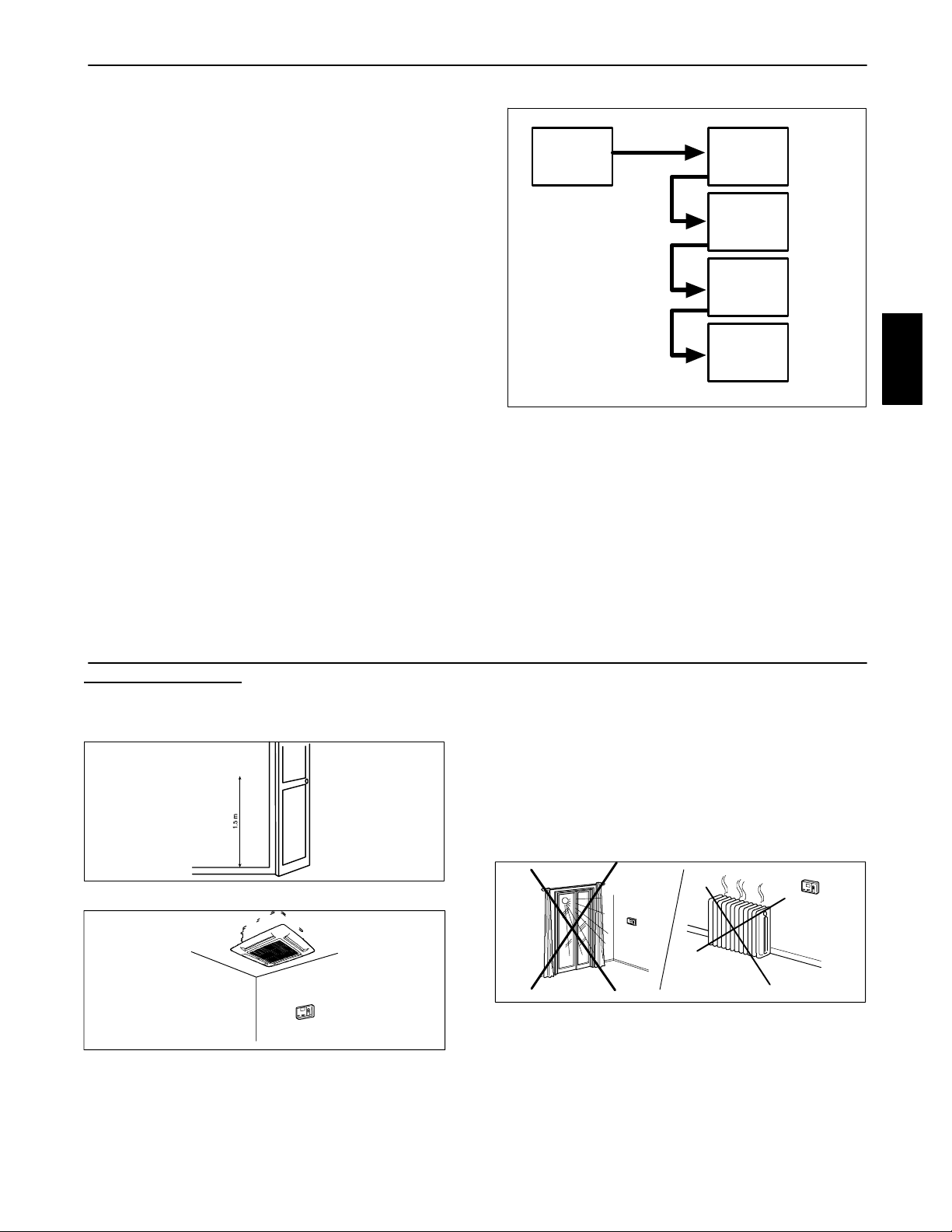
Room Controller Location
The Room Controller can be located anywhere. However, if the
installation requires the system in the location to use the air sensor
on the Room Controller; then, the controller should be mounted:
S Approximately 5 ft. (1.5 m) from floor.
Fig. 10 – Minimum Clearances
S In the same area where the unit is located, preferably on
an inside partitioning wall.
S On a section of wall without pipes or duct work.
If the air sensor on the Room Controller has been selected, it
should NOT be mounted:
S Close to a window, on an outside wall, or next to a door
leading to the outside.
S Exposed to direct light and heat from a lamp, sun,
fireplace, or other temperature--radiating object which
may cause a false reading.
S Close to or in direct airflow of a heating or cooling
supply.
S In areas with poor air circulation, such as behind a door
or in an alcove.
Maximum of 500 ft. (150 m) of total network wiring.
3
Page 4

G
enera
l
inf
ormation andcharacteristics
MOUNTING
!
ELECTRICAL SHOCK HAZARD
Failure to follow this warning could result in personal injury
or death.
Before installing the Room Controller, turn off all power to
the Unit that will supply power to the Room Controller.
S Turn OFF all power to unit.
33MC--URC
WARNING
P
G
C
S Match and connect equipment wires to proper terminals
in the connector block. Both power and communication
wires must be connected correctly for proper Room
Controller operation.
P
G
C
2
Fig. 13 – Connection Cable
S Push any excess wire into the wall and against mounting
base.
If the air sensor is being used on the Room Controller,
seal hole in wall to prevent air leaks.
Leaks can affect sensor operation.
Fig.11–MountingScrews
S Unscrew the side fixing screw.
S Open the Room Controller rear mounting base to expose
mounting holes. The base can be removed to simplify
mounting (snap apart carefully at hinge to separate
mounting base from remainder of the Room Controller).
S Route the Room Controller wires through the large hole
in the mounting base. Level mounting base against wall
(for aesthetic value only the Room Controller need not
be level for proper operation) and mark the wall through
the 2 mounting holes.
S Drill two 3/16” (5 mm) mounting holes in wall where
marked.
S Secure mounting base correctly (UP↑ ) to wall with 2
screws and anchors provided, (additional anchoring
holes available for more secure mounting if needed)
making sure all wires extend through hole in mounting
base.
S Adjust length and routing of each wire to reach the
proper terminal in the connector block on the mounting
base, with 1/4” (6 mm) of extra wire (strip only 1/4” (6
mm) of insulation from each wire to prevent adjacent
wires from shorting together when connected).
3
4
5
6
3 To indoor Unit
4 Rigid PVC conduit inside ∅ 1 --3/16” (30 mm) min.
5 Plaster approx. 1 --3/16” (30 mm)
6 Room Controller
7 Connector block
Fig. 14 – Mounting location
7
S Push the Room Controller snap hinge to the base.
S Tighten the side fixing screw.
Fig. 12 – Connection Cable
P
G
C
2
4
Page 5

G
enera
l
inf
UnitC
f
i
ormation andcharacteristics
!
ELECTRICAL SHOCK HAZARD
Failure to follow this warning could result in personal
injury or death.
Before connecting any wiring to the Room
Controller, turn off all power to the unit that will supply
power to the Room Controller.
Connection diagram for the following units:
1
emote connector
(J5) 5 pins
A Indoor unit
B Room Controller
1. Main electronic card
2. 4 pins terminal block placed on external control box
3. Wires supplied by the installer
4. Terminal block in the Room Controller
WARNING
Diagram 1:
40KMC and 40KMQ Cassette Family
Red
Black
White
A
2
P
G
C
34
S Loosen the screws of terminals P (DC Power), G
(GROUND) and C (SIGNAL) on the indoor unit and
Room Controller terminal blocks.
S As shown in diagram 1 connect the indoor unit terminal
block to the Room Controller terminal block.
Diagram 2:
Connection diagram for the following units:
40QNC and 40QNQ Highwall Family
1
emote connector
(J5) 5 pins
A Indoor unit
B Room Controller
1. Main electronic card
P
G
C
B
2. 4 pins terminal block placed on external control box
3. Wires supplied by the installer
4. Terminal block in the Room Controller
S Loosen the screws of terminals P (DC Power), G
(GROUND) and C (SIGNAL) on the indoor unit and
Room Controller terminal blocks.
Red
Black
White
A
2
P
G
C
34
P
G
C
B
33MC--URC
S By means of the screw provided with the Room
Controller Kit, secure the auxiliary terminal block (3
poles) to the main terminal box (6 poles).
S As shown in diagram 2.
Cables of auxiliary
terminal block
Red P
Black G
White C
Room Controller
terminal block
S Remove the cables from connector J5 inside the unit on
the electronic card to connect the cables supplied with
the Room Controller. Connect the indoor unit terminal
block to the Room Controller terminal block in the same
way as shown in diagram 2.
Wiring Materials required
(supplied by installer)
on
Room Controller Configuration Setup
To enter installer setup, hold the “MODE“ button down for 5
seconds. After 5 seconds, a “10“ will appear. This indicates that the
user is setting the first software configuration item. To check the
value of configuration item 10, press the “MODE” button. The
value of the Heat/Cool vs Cooling only remote configuration will
be displayed along with the “SET TEMP” icon to indicate that the
number displayed is the configuration data. To change the
Heat/Cool vs Cooling only remote Configuration, use the
“UP“/”DOWN“ buttons. To move to the next setting, press the
“MODE“ button again and the “10“ will be
The BOLD
values are the default values from the factory.
Item Value Description
10
11
12
guration
H Heat/cool remote
C Cooling only remote
On Room Thermistor Override Active.
Control and display room air temperature at the Room Controller control.
OF
C Temperatures displayed in degrees C
F Temperatures displayed in degrees F
Room Thermistor Override Inactive. Do not display room air temperature at the Room Controller and
control to New Modular DFS room air thermistor(s).
• 1 small screwdriver.
• Standard Double insulated wire recommended.
displayed. Press the up button and the display will change to “11”.
The mode button will toggle the display between the software
configuration index (i.e. “10“, “11“, etc.) and the configuration
value. The “UP”/”DOWN“ buttons will change either the index or
the value, which ever is displayed at the time. Press the ”FAN”
SPEED button to exit Configuration Setup Mode. This mode will
exit automatically after 10 seconds of no buttons being depressed.
Once a configuration value is changed, the last value displayed will
be the new configuration value for the Room Controller.
The only way to abort a configuration change is to change the
value back to its original value.
5
Page 6

UnitC
on
f
i
guration
5. Configuration Item 10 — Heat pump Vs Cooling mode
H -- The Room Controller will allow and display the
following modes: Off, Fan, Auto, Cool, Dry, and Heat.
C -- The Room Controller will allow and display the
following modes: Off, Fan, Cool, and Dry.
6. Configuration Item 11 — Room thermistor override
On-- Room Thermistor Override active. Units will be
controlled to the air temperature read in at the Room
Controller.
Keep it pressed for
at least 5 seconds
33MC--URC
Fig. 15 – Unit Configuration Setup
Louver Mode
To enter louver mode selection, make sure the Room Controller is
on and hold the “FAN” SPEED button down for 5 seconds. After 5
seconds, the selected louver setting will be displayed. Depressing
the up and down arrows will allow the user to modify the louver
setting between swing and auto.
The two setting will be displayed in the following way:
“S“ with Swing Louver Icon -- represents Swing Louver.
“A” with Auto Louver Icon -- represents Auto Louver.
Selection
Check the
value
up
down
OF-- Room Thermistor Override not active.
All units will be controlled to the room air thermistors
located on their own respective units.
7. Configuration Item 12 — Celsius Vs Fahrenheit
C -- Indicates that all temperatures will be displayed in
degrees C.
F -- Indicates that all temperatures will be displayed in
degrees F.
Change the
value
up
down
Next
item
A
To check/change
the values of items
11 and 12 go back
to point A
The fan icon shall also be displayed in the louver mode. Press
“FAN” SPEED button to exit LOUVER Mode Selection. This
mode will exit automatically after 10 seconds of no buttons being
depressed.
The only way to abort a louver change, is to change the value back
to its original value.
NOTE:
S If units are grouped to one Room Controller , all units will end
up having the same louver value.
S Louver Mode selection is not available during OFF mode.
Room Controller
ON
8. New DFS Modular Platform D Unit configuration
To enter New DFS Modular Platform D unit configuration, hold
the “UP“ and “DOWN“ buttons down together for 5 seconds while
the Room Controller is in off mode. After 5 seconds, a “20“ will
appear.
This indicates that the user is setting the first software
configuration item. To check the value of configuration item “20“,
press the “MODE” button.
The value for the New DFS Modular Platform D Heat Pump / AC
Only configuration will be displayed. To change the value, use the
“UP“ and “DOWN“ buttons. Once the value that you want is
selected, press the fan button to send that configuration data to the
unit.
Keep it pressed
for 5 seconds
Fig. 16 – Louver Mode Selection
up
down
Only the current value being displayed is transmitted. Once the
“FAN” button is pressed, the Room Controller will switch to
displaying the configuration index.
To move to the next setting, press the “MODE” button again and
the “20“ will be displayed.
Press the “UP“ button and the display will change to “21“. The
”MODE” button will toggle the display between the software
configuration index (i.e. “20“, “21“, etc.) and the configuration
value.
The“UP”/”DOWN” buttons will change either the index or the
value, which ever is displayed at the time.
Unit Configuration items 20 --24 are available at this point.
To change
the value
Automatic
(AUTO)
Or
Continuous
movement
(swing)
6
Page 7

UnitC
on
f
i
T
b
lesh
Item Value Description
1:Heatpump Unit Configuration
20
0:ACOnly(indoor unit with or without electric heaters) Defaults to Heat Pump
21 1--- 199 in increments of 1
22 0 –199 in increments of 1
0:StartinOffMode Auto Restart
24
1 : Start in last mode Defaults to “On”
guration
CCN Address of the unit
Defaults to 1
To display the hundreds, icon ON/OFF is .
Zone number --- Communications zone the system is located in
Defaults to 0
To display the hundreds, icon ON/OFF is .
This mode will exit automatically after 30 seconds of no buttons
being depressed.
NOTE: If units are grouped to one Room Controller, all units will
end up having the same configuration value.
Service test
There is a hidden service test mode that is initiated through a
combination of button presses when the remote is off. The
following combination must be pressed within a 6 seconds period:
mode
DOWN--FAN--UP--FAN--MODE
Once in service test mode, the service test mode message will be
sent, and “Sr“ will be displayed in the temperature icons until the
“DOWN“ bu tton is pressed.
During Service Test mode all the icons are off, the only button that
is active is the “DOWN” button.
To cancel Service Test Mode, press the “DOWN“ button to send a
normal message with “OFF“ mode.
Service Test Mode automatically times out after 30 minutes and the
remote will operate normally.
rou
ooting
S When test mode is selected, the unit will operate as
described below:
⎯ The Unit Status (Green) and Timer (Yellow) LEDS
blink every 2 seconds.
⎯ The indoor fan will operate according to
user--selected speed. If user selected speed is Auto,
the fan will run in High speed.
⎯ If the unit is configured as an A/C Only unit, it will
operate in cool mode with demand.
S The louver will operate according to user--selected
position. If user selected louver is Auto, louver operates
according to cool louver.
⎯ If the unit is configured as a Heat Pump unit, the
louver will operate according to user--selected
position. If user selected louver is Auto, louver
operates according to auto heat or cool louver based
on operating mode.
The unit will run in cool mode for 3 minutes, then it
will run in heat mode for 2 minutes, or until the
indoor coil is greater than 104_F. The unit will run
in cool mode until test mode is exited.
Any of the following will cancel the test Mode:
S When the unit is turned off by the controller.
S If the power is cycled during the Test Mode, the unit will
return to its normal operating mode.
S After 30 minutes of receiving the last valid test request
message.
S Fail Mode
33MC--URC
Symptom Possible Cause Things to check Solution
No LCD display
+12 volts applied to
Room Controller at
the correct terminals
and still does not
operate
1) mis---wiring of the 12 volt power
to Room Controller control.
2) Power not online
3) No 12 volts between P and G of
terminal block.
1) The Room Controller is damaged.
Verify that + 12 V and Ground are connected to
the proper terminals of the Controller.
Reference Installation wiring section for correct
connections
Check that the units main power is connected.
The main control board should be operating
normally
Check the installation of the J6 plug on the
main control board.
7
After disconnecting the
power, correct the wiring
problem and re --- cycle
power.
After verifying the wiring
to the Room Controller,
re--- cycle the unit power.
After disconnecting the
power, correct the wiring
problem and re --- cycle
power.
Change the Room Controller and re-- -cycle power.
Page 8

33MC--URC
Copyright 2006 Carrier Corp. S 7310 W. Mo rris St. S Indianapolis, IN 46231
Manufacturer reserves the right to change, at any time, specifications and designs without notice and without obligations.
Printed in U.S.A. Edition Date: 07/06
8
C a t a l o g N o . 3 3 M C --- U R C --- 1 S I
Replaces: NEW
 Loading...