

Page 1

Electronic and Mechanical Air Cleaner
|—8i"-4
31MC
UNIT
31MC,MP114
31MP214; ^
31MC,MM,MP220
Fig. 1 — Dimensions, Electronic and Mechanical Air Cleaners
GENERAL
The Carrier 31MP plate-type and 31 MM mediatype electronic air cleaners and the 31MC highefficiency mechanical air filters, all shown in Fig.
1, are designed for use with residential and light
commercial forced-air heating and/or cooling sys
tems. They can be installed vertically or horizont^lji in. the ductwoi;ic„9r at the furnace. The
units are easily converted in the field from right to
left hand by removing the air cleaning components
and reassembling them in reverse order. Cabinets
will support a weight of 400 lb when installed
beneath a vertical furnace or air-handling unit.
Package Contents — The 31MP and 31 MM elec
tronic air cleaner packages and the 31MC highefficiency filter package consist of:
1. One31MP, 31MMor31MCunit.
2. Two base angle air baffles.
3. A template for preparing the furnace opening.
4. A bag of hardware consisting of 6 no. 8B x
1/4-in. long screws, 6 no. 8 speed nuts and a
small bag containing wire nuts for making
electrical connections.
5. A coil of foam tape.
6. Package of replacement media (31MM Models
only).
7. An installer’s packet.
SIMM
A (in.)
21’/4
28V,
31MP
When unpacking the unit, if any in-transit
damage is observed, file a claim with the trans
portation agency. Since the air cleaner components
are packed in a single carton, be sure to inspect
all packing materials before discarding.
Application — Install the electronic air cleaner
where all of the air circulated by the system will
pass thru it. The best location is in the return air
duct close to the blower compartment. This
location provides the most even air flow distribu
tion across the face of the electronic cells or
mechanical filter element and also allows the air
cleaner to keep the blower and motor clean. In a
cooling system, the air cleaner keeps the evap
orator coil clean.
When it is not possible or economically feasible
to mount the air cleaner in the return air duct,
consider installing the unit in the air discharge
duct. However, give special consideration to the
following factors when planning such an
installation.
1. Even air flow distribution across the face of the
electronic cells may be difficult to achieve. Use
turning vanes and transitions where necessary.
2. Put the air cleaner upstream from the coil in a
cooling system, if possible. The electronic air
cleaner or mechanical filter will help keep the
© Carrier Corporation 1975
Form 31MP-2SI
Page 2

coil clean, reducing maintenance costs. Also, air
coming from the coil will frequently be near
100% relative humidity.
3. The air flow temperature thru the air cleaner
must be within 40 F to 125 F.
Location — Because air-handling systems vary
greatly in arrangement and style, factors such as
accessibility, ambient temperature ratings, tran
sitions, and other requirements must be carefully
considered.
In crawl space or attic installations (uncondi
tioned space), air cleaner must be insulated the
same as ductwork.
The unit must be readily accessible for periodic
inspection and cleaning of the prefilter and elec
tronic cells to maintain maximum efficiency and
trouble-free operation. A minimum of 30 in. of
clear area should be left in front of the air cleaner
for cell and prefilter removal.
The air cleaner must be installed where the
temperature will be within a 40 F to 125 F range.
Humidifiers — Location of the system humidifier is
important to the operation of the electronic air
cleaner or mechanical filter.
When an evaporative-type humidifier is used, it
may be installed between the furnace warm air
duct and the return air duct without affecting the
electronic air cleaner.
An atomizing-type humidifier must be installed
downstream from the air cleaner. If the atomizingtype humidifier is installed upstream, high
humidity, salts and minerals will decrease the
efficiency of the electronic cell and cause service
problems or damage the high-efficiency filter
element in the mechanical air filter.
Outdoor Air — When outdoor air is added to the
return air duct, sufficient heat must be added to
maintain the return air temperature at 40 F mini
mum. Lower temperatures can cause ionizer wire
failure under certain conditions. Two methods are
recommended:
1. Mixing baffles or vanes. When outdoor air is
added, make certain that it is far enough ahead
of the air cleaner to be mixed and warmed
properly. If not, baffles must be installed to
force mixing of the air.
2. Preheat coil. If a large amount of outdoor air is
used, it must be heated. A thermostat should be
used to control the heater. (A strip heater or
hot water coil are typical heaters.)
INSTALLATION PROCEDURE
Remove Filter and Clean Blower Compartment
Before Starting Installation.
1. Remove and discard the old filter if one is used.
2. Thoroughly clean the blower compartment.
The air cleaner cannot remove (firt from the
blower compartment or distribution ducts.
Installation of 31MP Plate-Type or SIMM MediaType Air Cleaner
1. Remove power door by turning fastener knob.
Fig. 2, item 5, counterclockwise until power
door is free. Slide out prefilter and air cleaner
cells.
1 — Cabinet
2 - Collector Cell (31 MP)
3 — Prefilter
4 — Power Door
5 — Fastener Knob
6 — Test Button
Fig. 2 — Electronic Air Cleaner Components,
Model 31 MP
7 — Indicator Light
8 - ON-OFF Switch
9 — Ceramic Insulators
10 — Opening for Power Supply
11 — Junction Box Cover
2. Unit can be installed with air flow thru the
cabinet in either direction. No changes to the
cabinet are necessary when reversing the air
flow direction thru air cleaner. See Fig. 3.
3. Apply template, supplied in package, to side of
furnace and prepare the opening in side of
furnace according to instructions on template.
4. Prepare return air duct for installation of unit.
Allow a minimum of 30-in. clearance in front
of power door for servicing.
5. Return air duct should use full cabinet open
ing. Run duct straight into unit. Use an elbow
with turning vanes if duct takes a sharp turn
close to air cleaner inlet. Do not baffle off any
portion of entering air side of air cleaner
When it is necessary to change duct size close
to the air cleaner, use gradual transitions to
reduce turbulence. See Fig. 4.
Page 3

Fig. 3 — Left- and Right-Hand Assemblies
-------
L.
RETURN
AIR
DUCT
Fig. 4 — Transition from Smaller Ducts
6. When installing unit at bottom return opening
of an upflow furnace;
a. Center furnace on air cleaner cabinet and
remove components from cabinet.
b. Field-fabricated support not required on
Carrier furnaces.
c. When the furnace is larger or smaller than
the air cleaner, baffle off any mismatch
between furnace and air cleaner with
baffles, included with unit. Additional
support, such as support legs, is recom
mended when furnace overhangs the air
cleaner.
9. Slide prefilter and air cleaner cells into cabinet.
Units are shipped for right-hand installation.
To convert from a right- to a left-hand unit,
reverse the position of the prefilter and the air
cleaner cells in the cabinet as indicated in Fig.
3. Be sure the air flow arrows are pointing to
the direction of air flow thru unit, and the
ionizer wires in the cell are adjacent to the
prefilter. The 31MC220 high-efficiency me
chanical filter does not have a prefilter or
electronic cell. Simply reverse position of filter
element to change from right- to left-hand. An
air flow direction arrow is stamped on the
filter element.
10. Remove junction box cover on 31 MM and MP
units only. Fig. 5, item 1, located below
receptacle, item 2, on top inside of cabinet.
Install strain relief in opening for 120-volt
input supply, Fig. 2, item 10, in top of
cabinet. Connect 120-volt supply pigtails in
junction box with wire nuts provided, and
connect ground wire to green pigtail provided.
Wire supply voltage from fan circuit of system
to have air cleaner operating only when unit
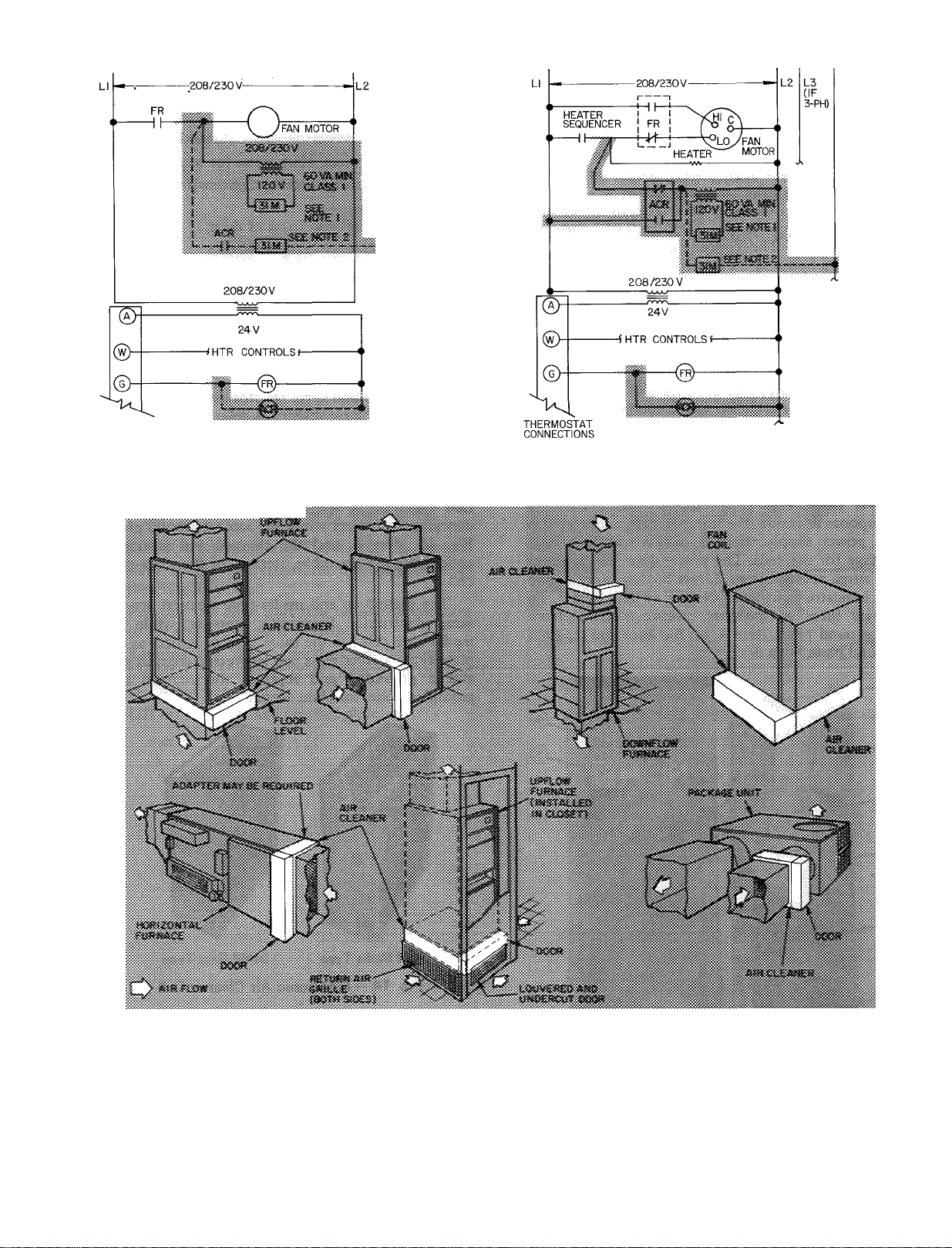
fan is running. See Fig. 6, 7, 8 and 9 for
typical furnace wiring diagrams. All wiring
must comply with applicable local and
national codes.
prevefit » cormt fr««» atsl
7. If a filter flag is used to indicate a clogged
filter, install it downstream of cleaner, follow
ing instructions furnished with the filter flag.
8. Seal all joints on downstream side of air
cleaner.
11. Replace power door. Turn fastener knob
clockwise until power door is securely
fastened, thus ensuring good electrical contact
between power door and unit components.
Diverse installations are shown in Fig. 12.
12. Check over the installation for correct sheet
metal and electrical work.
Page 4

C
3 — Top Guide 6 — Screw for Holding Top Guide
NOTE: The 2-cell unit (-220) shown; the 1-cell units (-114, 214)
have one contactor in the door
Fig. 5 — Junction Box and Top Guide
CONNECTIONS
Fig. 6 — Typical Furnace Wiring with Single-Speed
Fan Motor
THERMOSTAT
CONNECTIONS
Fig. 7 — Typical Furnace Wiring with Multispeed
Fan Motor and Air Cleaner Relay
THERMOSTAT
CONNECTIONS
Fig. 8 — Typical Furnace Wiring with Multispeed
Fan Motor and Sail Switch
115V HUMIDIFIER
!
---------
I DIRECT DRIVE WIRING
F| F2 12 5 ^
-IH
fan I 41 MED LO
SWITCH
115V HUMIDISTAT
HUI ,
3 ! 6
________
—((^ H ; H -------------
—il
24V HUMIDISTAT 24 V HUMIDIFIER
*Ar
LIMIT
m
____
LIMIT
]J
VAL2
--------------
■ —
--------
HAF VALVE
(WHEN USED)
---
CHWO
<2^>0-<2)
CONTACTOR IN REMOTE \
CONDENSING UNIT
-<f{^>-------------------'
BLOWER RELAY
Fig. 9 — Electronic Air Cleaner Wired into
58ES or 58GA Furnace Wiring
GAS
-----
-------------
1
LEGEND for Fig. 6, 7, 8, 9,10 and 11
31 MM or MP wiring FS
ACR — Air Cleaner Relay
FR — Fan Relay SS
(Location of ACR LS
is optional ) PS
(FR may be installed Trans
in furnace ) V
HAF
HR
— Fan Switch
— Heat Assist Fan Switch
— Humidifier Relay
— Limit Switch
— Pilot Switch
— Sail Switch
— Transformer
— Gas Valve
NOTES for Fig. 10 and 11
1 Transformer must be used on 208-230 V supply Exceptions:
a) 208-3 Phase wye
b) 208/230-1 Phase with reliable ground
2 Dashed lines indicate wiring for:
a) 208-3 Phase wye
b) 208/230-1 Phase with reliable ground
Page 5
L3
(IF
3-PH)
NEUTRAL
OR
GROUND
NEUTRAL
OR
GROUND
(
X-
THERMOSTAT
CONNECTIONS
Fig. 10 — Typical Fan-Coil Wiring with 208/230-v
Supply and Single-Speed Fan Motor
Fig. 11 — Typical Fan-Coil Wiring with 208/230-v
Supply and Multispeed Fan Motor
Fig. 12 — Installation of 31MC Mechanical or 31 MM or MP Electronic Air Cleaner
Installation of 31 MC Mechanical Air Filter
1. Remove the access door and slide out mechani
cal filter.
2. Follow steps 2, 3, 4, 5, 6, 7 and 8 of
Installation Procedure in this booklet.
3. Slide mechanical filter into cabinet. Be sure
arrow on filter is pointing in the direction of air
flow. Secure access door to cabinet with
fastener knob.
Page 6
OZONE
The odor of ozone may be noticeable during
operation of an electronic air cleaner. A somewhat
higher ozone generation rate during the first week
or 2 of operation may be caused by sharp edges on
some of the new high-voltage parts. Normal use
dulls these sharp edges in a short time.
The odor of ozone is detectable by an average
person at levels as low as 0.003 to 0.010 parts per
million (ppm). The concentration of ozone pro
duced in a home by an electronic air cleaner ranges
from 0.006 to 0.015 ppm. Average concentrations
of ozone in the air of major cities range from 0.020
to 0.040 ppm and even higher. This is well above
the level produced by an electronic air cleaner.
SERVICE
Cabinet Assembly, Fig. 2, consists of a power door
item 4, which is attached to the cabinet, item 1, by
means of a fastener knob, item 5. Inside the
cabinet are the prefilter, item 3, and the cell, item
2, both of which can be easily slid out of cabinet
for cleaning and service.
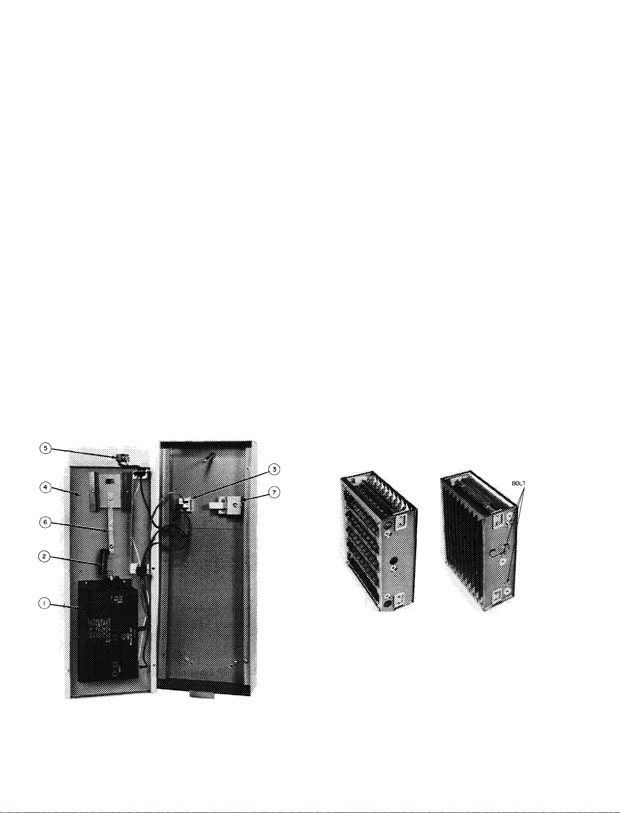
Power Door, Fig. 13, retains all the air cleaning
components inside the cabinet and also contains
the power supply, item 1, which produces high
voltage for the cells. The power door also contains
the surge resistor, item 2, test button, item 7, and
the indicator light and ON-OFF switch, item 3. To
service these components, remove 6 screws from
the ground plate, item 4, on the door and separate
ground plate from door.
INDICATOR LIGHT AND ON-OFF SWITCH are
both in one unit. Replace complete assembly when
necessary.
1. Disassemble power door. See Power Door.
2. Disconnect wires. Mark wires for reassembly.
3. Compress springs holding light/switch assembly
in door.
4. Pull assembly from front of door.
POWER SUPPLY
1. Disassemble power door. See Power Door.
2. Remove surge resistor connection at the power
supply.
3. Remove 4 sheet metal screws holding the power
supply to the plate.
SURGE RESISTOR is riveted to the bus bar, item
6. The bus bar and surge resistor assembly must be
replaced if the surge resistor is defective.
1. Disassemble power door. See Power Door.
2. Disconnect surge resistor at power supply.
3. Remove screws holding the bus bar.
Cell — Plate-type and media-type. Fig. 14. The cell
contains the ionizer wires, the ionizer ground plate.
Fig. 15, item 1, and the charged and grounded
collector plate assembly, item 3, of the plate-type
cell.
The plate-type and media-type cleaners are the
same electrically. Physically, however, while the
media-type cell has the same type of ionizer as the
plate-type, a fiber glass pad between a charged grid
and a grounded grid replaces the charged and
grounded collector plate assembly.
1 — Power Supply
2 — Surge Resistor
3 — Indicator Light and
ON-OFF Switch
Fig. 13 — Power Door
4 5 6 7 -
Ground Plate
Receptacle
Bus Bar
Test Button
31 MM Media Type 31MP Plate Type
Fig. 14 — Electronic Air Cleaner Cell
DISASSEMBLING THE PLATE-TYPE CELL -
Refer to Fig. 15.
1. Remove 4 sheet metal screws, item 8, holding
the ionizer ground plate, item 1, to the cell
structure, item 2.
2. Lift off the ionizer ground plate.
3. Remove 3 bolts from each end panel. See Fig.
14.
Page 7
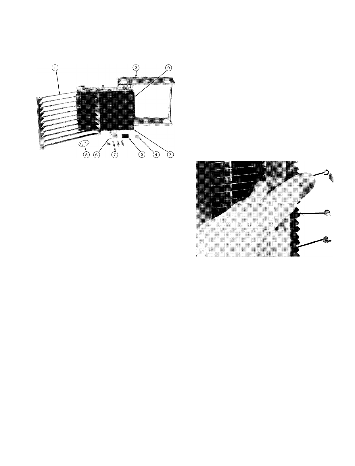
4. Remove the cell structure which consists of a
riveted assembly of 2 end panels and 2 angles.
ROUND INSULATORS, Fig. 15, item 4, may be
lifted from the rod ends when the cell structure is
'l
removed.
Replacing Ionizer Wires, Fig. 16 — The following
procedure is recommended for replacing broken
ionizer wires:
1. Remove ionizer ground plate. See Dis
assembling the Plate-Type Cell.
2. Remove the broken ionizer wire. Be sure no
pieces of the broken wire remain in the cell to
cause shorting.
3. Secure end of new ionizer wire in loop of
bottom ionizer wire spring.
4. Depress top ionizer wire spring with finger as in
Fig. 16.
5. Secure top end of ionizer wire in loop of
ionizer wire spring while it is depressed.
6. Inspect wire installation and relieve finger
pressure from ionizer wire spring.
7. Replace ionizer ground plate.
1 — Ionizer Ground Plate
2 — Cell Structure
3 — Charged and Grounded
Collector Plate Assembly
4 — Round Ceramic Insulator
Fig. 15 — Disassembled Cell, Model 31MP
5 — Contact Plate
6 — Rectangular Ceramic Insulator
7 — Bolts
8 — Sheet Metal Screws
9 — Bus Bar
RECTANGULAR INSULATORS, Fig. 15, item 6.
1. Remove the cell structure. See Disassembling
the Plate-Type Cell.
2. Remove the large bolt that holds the insulator
to the end of the plate assembly.
3. Remove the sheet metal screw holding the
insulator and contact plate, item 5, to the end
of the bus bar, item 9.
4. Lift off insulator and contact plate.
Fig. 16 — Replacing Ionizer Wire
Page 8

COMPLAINT
Indicator Light Off
Arc Test Button
Produces No Snapping
Noise
Unit Snaps or Arcs
Continuously
Humming Noise
Air Cleaner Doesn't
Clean Dirt
Radio or T.V.
Interference
White Dust on
Furnishings
SERVICE PROBLEM ANALYSIS
POSSIBLE CAUSES
Shorted cells
Shorted top guide
Defective light
Defective power supply
i Defective push button
Blower not operating
Cells wet either due to high humidity or from being
washed
Shorted cells
Shorted top guide
Defective push button
Defective surge resistor
Defective power supply
System blower not operational
Humidifier upstream
Cells loaded
Line voltage too high
Cells need cleaning
Broken ionizer wire
Broken contact spring in top guide of power door
Broken insulator in cell
Broken insulator in power door or contact tray
Foreign material lodged between plates or in ionizer
Bent plates or media grille for media EAC
Broken or deformed arc test button assembly
Improper wiring connections
Loose ionizer wires
Excessively dirty ionizer or collector
Lack of power to cells due to improper alignment of
contact spring on power door to cells in top guide
Defective interlock plug or receptacle
Air volume too great
Leaks in ductwork on downstream side of air cleaner
Dirty air not being delivered to air cleaner
Damaged or improperly placed dirt collecting pad
(media-type only)
Uneven air distribution across face of unit which may
be indicated by uneven loading pattern of dirt in
collector section of air cleaning cells
The entering air side of collector stage should be evenly
covered with dirt. In the case of the 020 sized units, each
cell should have an even loading pattern.
Accumulation of foreign particles lodged in ionizer
section
Unit improperly grounded
Ground line of power supply not properly grounded
Loose ionizer wires
Loosely connected components, or loose connections
Defective power pack
Dents in collector section of ionizer section
Damaged dirt collecting pad (media-type only)
Improperly installed dirt collecting pad (media-type
only)
Occasionally a "white dust" might be noticed in bed-
rooms or newly furnished rooms. This is mainly com
posed of lint which because of its weight, settles before
it reaches your unit. This is not mixed with airborne
dirt. It has no staining or soiling properties and will
j lessen as the excess lint works out of fabrics.
SOLUTION
See Troubleshooting Procedure.
f
Energize blower.
Cells will dry.
See Troubleshooting Procedure.
Energize blower.
Adjust line voltage.
Clean cells.
Replace wire.
Replace spring.
Replace insulator.
Replace insulator.
Remove object.
Straighten.
Replace or repair.
Check wiring.
Replace or repair.
Clean as per Maintenance
Instructions, Owner's Manual
Adjust alignment or replace spring.
Replace.
Reduce air volume to design cfm.
Seal.
Insufficient air — check return air
grilles for obstruction by furniture,
drapes, etc.,and remove, check blower
for proper air flow.
Replace or reposition as per Maintenance Instructions, Owner's Manual.
Install turning vanes or air baffles
oi if--* mwim sir 5^
Remove.
Provide good ground to unit.
Correct same.
Replace.
Tighten.
Replace.
Straighten.
Clean or replace.
Reposition.
Only air taken thru return grilles is
cleaned.
Page 9
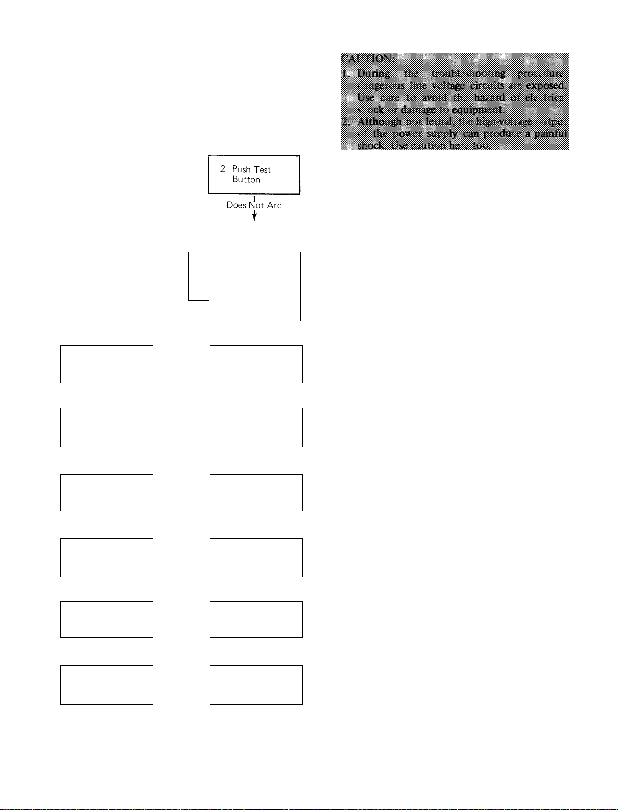
. TROUBLESHOOTING PROCEDURE
The following troubleshooting procedure has
been designed to speed the serviceman’s work and
f , ensure that any malfunction in the electronic air
" cleaner is quickly detected and properly repaired.
Troubleshooting Sequence Chart
1 Blower on,
Energize EAC
Ligh Off
3 Push Test
Button
I
Does Not Arc
t
4 Remove Cells,
Replace Door
Light Off
t
5 Push
Test Button
1
Does Not Arc
t
6. Check Line
Voltage
Line Voltage Correct
t
7 Disconnect Surge
Resistor, Energize
Power Supply
1
Light Off
t
8 Check Output of
Power Supply
9 Defective Light
Circuit in
Power Supply
—Light Orp»>-
Unit
Arcs
Unit
Arcs
Light
On
___
,Unit ^
Arcs
Incorrect
Voltage
— Light On-^
__
Low or
No Output
Check Surge
Resistor
Test Button
EAC Operating
Properly
Check Light
Circuit
Check Ceils,
Contact Tray.
Surge Resistor
Check Light,
Light Circuit and
Cells
Check Voltage
Source and
Wiring
Replace
Surge Resistor
Replace
Power Supply
Troubleshooting the electronic air cleaner can
be accomplished with only a few tools.
• Screwdrivers ^ long shank, plastic or rubber
handles; 2 required for some arc checks.
• Jumper cord.
• Voltmeter with 25 kv DC probe.
• Grounding wire.
Most of the steps can be performed by observ
ing the indicator light in the ON-OFF switch. This
light is powered from the high-voltage circuit on
the high-voltage transformer and is on whenever
the high-voltage transformer is working properly.
This procedure is outlined in the Trouble
shooting Sequence Chart. A complete description
is provided on the following pages.
This troubleshooting procedure description is
divided into 2 sections;
1. Diagnostic Tests — The numbered steps cor
respond to the numbered steps on the Trouble
shooting Sequence Chart. Follow this sequence
of tests to locate the cause of a failure within
the air cleaner.
2. Component checks explain how to locate a
faulty component within an assembly, or how
to prove a component good or bad.
Diagnostic Tests
STEP 1 - ENERGIZE ELECTRONIC AIR
CLEANER
a. Be sure electronic cells and prefilter screens are
clean, dry and properly installed in cabinet.
b. Energize electronic air cleaner.
— Put switch at “On” position.
— Energize blower.
c. Check on indicator light operation.
— If light is off, failure is in the electronic air
cleaner — go to Step 3.
— If light is on — go to Step 2.
STEP 2 - PUSH TEST BUTTON - INDICATOR
LIGHT ON
Test Button Fig. 2, item 6, on the cleaner
access door, provides a simple easy-to-use method
of checking for correct high voltage in electronic
cell. When pushed, it shorts from insulated high-
voltage components to ground. From the sound of
the resulting arc, serviceman may determine
whether or not high voltage is supplied to elec
tronic cell.
Page 10
a. Turn electronic air cleaner on and energize
system fan to power the electronic air cleaner.
b. Push test button. Snapping sounds (arcing
noise) indicate that air cleaner is working
properly.
c. If no arcing noise is heard, check for continuity
thru resistor, and then check push button
assembly.
STEP 3 - PUSH TEST BUTTON - INDICATOR
LIGHT OEF
a. Turn on electronic air cleaner and energize
system fan to power the electronic air cleaner.
b. Push test button. Snapping sound indicates that
electronic air cleaner is working properly. Fail
ure is in the indicating light circuit. See Step 9
— Defective Light Circuit.
c. If no snapping sound is heard, go to Step 4.
STEP 4 ~ REMOVE CELLS
a. Turn off blower circuit and remove electronic
cells.
b. Replace power door and reenergize power
supply. Put switch in “On” position and ener
gize blower.
c. If light comes on now, check cells and top
guide assembly for proper contact. Check surge
resistor. Refer to Step 7.
d. If indicator light does not light, go to Step 5.
STEP 5 - PUSH TEST BUTTON
a. Energize power supply as in Step 1, a and b.
b. Push button. Snapping sound indicates proper
high-voltage output from power supply and
surge resistor. Failure is probably in cells or top
guide assembly or in the light circuit within the
power door. Check cells, light and light circuit.
If light is faulty, replace switch and light
assembly.
c. If there is no arcing or snapping, go to Step 6.
STEP 6 - CHECK LINE VOLTAGE
a. Remove access door and energize blower. Line
voltage to the air cleaner can be determined
using a neon test lamp and inserting prongs into
receptacle on cabinet. If voltage checks low on
the voltmeter, trace wiring back to determine
cause of problem. (Refer to wiring application
diagram.)
b. If voltage checks correctly, open power supply
door by removing the 6 screws from the door
base. Use ohmmeter to check continuity of
low-voltage wiring, taking care to check switch
in both the “Open” and “Closed” position. If
circuitry checks correctly, go to Step 7.
STEP 7 - DISCONNECT SURGE RESISTOR.
ENERGIZE POWER SUPPLY
a. Refer to internal components of the power
door. Fig. 13.
b. De-energize system blower. Remove lug at
output end of power supply and remove surge
resistor from high-voltage circuit.
WIRE
CONN
BLK
<»
WHT Q
GRN
-®
r
INTERLOCK
(DO NOT BYPASS)
----------------______
-----------
) II5V 60HZ
1 FIELD WIRING
FIELD WIRED GROUND
POWER
RED
VIO
SUPPLY
PRI
DC
BLK
WHT
0^0-
PWR
SW
HV-^W
>
—o'
PUSH
TEST
ASSY
UNIT
X
Fig. 17 — Internal Schematic for 31MP and SIMM
Electronic Air Cleaners
Using jumper cord and grounding cord, provide
c.
circuitry between plug on power door and
receptacle on cabinet. Attach grounding wire
between power door base and cabinet. See Fig.
18.
d. Energize system blower and turn switch to
“On” position. Glowing light indicates faulty
surge resistor; replace same. If light still is not
glowing, go to Step 8.
STEP 8 - CHECK OUTPUT OF POWER SUPPLY
a. With blower and electronic cleaner on, measure
output of power supply using voltmeter with
mating high-voltage probe. If output reads
between 6500 to 7500 volts DC, problem is
defective light circuit. Go to Step 9. If output is
low, replace power supply.
STEP 9 - DEFECTIVE LIGHT CIRCUIT
а. With power on, measure voltage at light circuit
terminals on power supply. Output should read
between 90 — 2000 volts. If output is correct,
replace switch and light assembly. If there is no
output, replace power supply.
Component Checks
CHECK ELECTRONIC CELLS
Visual Inspection — Carefully examine the elec
tronic cells. Look especially for:
1. heavy dirt accumulation
2. bent collector plates (plate cleaner)
3. broken ionizing wires
4. dirt accumulation on insulators
5. contact springs — broken or dirty — ionizer and
collector damage
б. deformed pleat grids (media cleaner)
10
Page 11
Check for Short Circuits — Use an ohmmeter to
check resista'nce between the outside frame of the
cell and the high-voltage contact. In each case, the
resistance should be infinite (open circuit).
CHECK TOP GUIDE ^ (2000 Cfm Models)
1. Remove top guide assembly from cabinet by
removing the single screw below junction box.
See Fig. 5.
2. Using ohmmeter, check for shorts between
contact spring and ground. Resistance should
be infinite.
3. Examine insulators for cracks or heavy dirt
buildup. Clean if dirty; replace if cracked.
CHECK SURGE RESISTOR - See Step 7 under
Diagnostic Tests.
The function of the surge resistor is to protect
the power supply from instantaneous “spikes” of
high-voltage power that occur when the unit arcs.
This important component must be operating
satisfactorily to adequately protect the power
supply. Do not bypass.
CHECK LIGHT AND LIGHT CIRCUIT - See Step
9 under Diagnostic Tests.
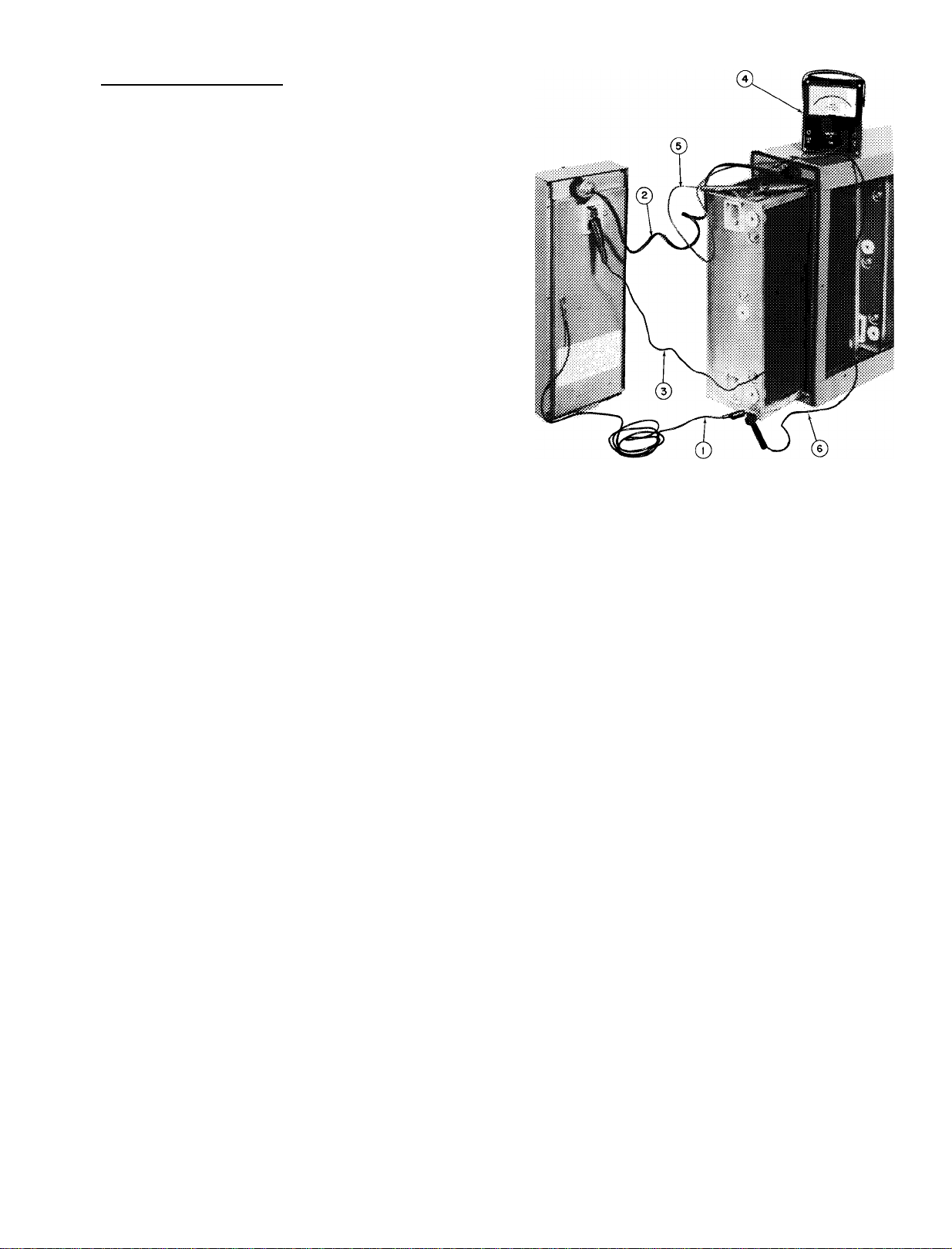
1 — Ground Wire
2 — Patch Cord for 115-v
Supply Voltage
3 — High Voltage Wire
(7500-v DC)
Fig. 18 — Test Circuit Between Power Door
4 — Voltmeter with 25-Kv
DC Probe
5 — High Voltage Lead from Meter
6 — Common or Ground Lead
from Meter
and Cabinet
11
Page 12

For replacement items use Carrier Specified Parts.
Manufacturer reserves the right to discontinue, or change at any time, specifications or designs without notice and without incurring obligations.
Tab 1 Form 31 MP-2SI Supersedes 31MP-1 SI Printed in U.S A 4-75 Codes F and MS Catalog No 533-105
 Loading...