

Carrier 30HXC110, 30HXC090, 30HXC130, 30HXC120, 30HXC080 Installation, Operation And Maintenance Instructions
...Page 1
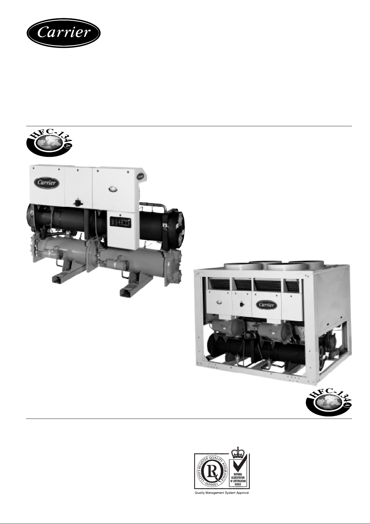
30HXC 080-375
30GX 082-358
Screw Compressor
Water-Cooled Liquid Chillers and
Air-Cooled Liquid Chillers
30HXC Nominal cooling capacity 290-1325 kW
30GX Nominal cooling capacity 285-1205 kW
50 Hz
GLOBAL CHILLER
Installation, operation and maintenance instructions
Page 2

The cover photograph is for illustrative purposes only and is not part of any offer for sale or contract.
Page 3

List of contents
1 - INTRODUCTION .................................................................... 4
2 - SAFETY CONSIDERATIONS ............................................... 4
3 - DIMENSIONS, CLEARANCES,
WEIGHT DISTRIBUTION..................................................... 5
3.1 - 30HXC 080-190 .......................................................................... 5
3.2 - 30HXC 200-375 .......................................................................... 6
3.3 - 30GX 082-182............................................................................. 7
3.4 - 30GX 207-358............................................................................. 8
4 - PHYSICAL DATA 30HXC ...................................................... 9
5 - ELECTRICAL DATA 30HXC................................................. 9
6 - ELECTRICAL DATA FOR UNITS WITH HIGH
CONDENSING TEMPERATURES ......................................11
7 - PHYSICAL DATA 30GX ....................................................... 12
8 - ELECTRICAL DATA 30GX ................................................. 12
9 - APPLICATION DATA........................................................... 13
9.1 - Unit operating range .................................................................. 13
9.2 - Minimum chilled water flow..................................................... 13
9.3 - Maximum chilled water flow .................................................... 13
9.4 - Variable flow evaporator ........................................................... 14
9.5 - System minimum water volume................................................ 14
9.6 - Cooler flow rate (l/s) ................................................................. 14
9.7 - Condenser flow rate (l/s) ........................................................... 14
9.8 - Evaporator pressure drop curve................................................. 15
9.9 - Condenser pressure drop curve ................................................. 16
9.10 - Flow controllers ...................................................................... 17
12 - ELECTRICAL CHARACTERISTICS ................................ 23
12.1 - 30HXC .................................................................................... 23
12.2 - 30GX ....................................................................................... 23
12.3 - 30HXC/GX ............................................................................. 23
13 - RECOMMENDED WIRE SECTIONS ................................ 24
13.1 - Field control wiring ................................................................. 25
14 - MAJOR SYSTEM COMPONENTS AND OPERATION
DATA ....................................................................................... 26
14.1 - Geared twin screw compressor ............................................... 26
14.2 - Evaporator ............................................................................... 26
14.3 - Condenser and oil separator (30HXC) .................................... 26
14.4 - Oil separator (30GX)............................................................... 26
14.5 - Electronic Expansion Device (EXD) ...................................... 26
14.6 - Economizer.............................................................................. 26
14.7 - Oil pumps ................................................................................ 27
14.8 - Motor cooling valves............................................................... 27
14.9 - Sensors .................................................................................... 27
14.10 - Thermistors............................................................................ 27
14.11 - 30GX fan arrangement .......................................................... 28
15 - MAINTENANCE.................................................................... 29
15.1 - Refrigerant charging - adding charge ...................................... 29
15.2 - Indication of low charge on a 30HXC system......................... 29
15.3 - Pressure transducers ................................................................ 30
15.4 - Oil charging - low oil recharging ............................................ 30
15.5 - Integral oil filter change .......................................................... 30
15.6 - Filter change-out schedule....................................................... 30
15.7 - Filter change-out procedure..................................................... 30
15.8 - Compressor replacement ......................................................... 30
16 - ST A RT-UP CKECKLIST FOR 30HXC/GX LIQUID
CHILLERS.............................................................................. 32
10 - INSTALLATION ...................................................................... 17
10.1 - Check equipment received ...................................................... 17
10.2 - Moving and siting the unit ...................................................... 17
11 - LIFTING INSTRUCTIONS.................................................... 18
11.1 - 30HXC 080-190 ...................................................................... 18
11.2 - 30HXC 200-285 ...................................................................... 19
11.3 - 30HXC 310-375 ...................................................................... 19
11.4 - 30GX 082-162 ......................................................................... 20
11.5 - 30GX 182 ................................................................................ 20
11.6 - 30GX 207-267 ......................................................................... 21
11.7 - 30GX 298-358 ......................................................................... 21
11.8 - Piping connections................................................................... 22
3
Page 4

1 - INTRODUCTION
Prior to initial start-up of the 30HXC and 30GX unit, those
involved in the start-up, operation, and maintenance should be
thoroughly familiar with these instructions and other necessary
job data. This book provides an overview so that you may
become familiar with the control system before performing
start-up procedures. Procedures in this manual are arranged in
the sequence required for proper machine start-up and
operation.
2 - SAFETY CONSIDERATIONS
30HXC and 30GX liquid chillers are designed to provide safe
and reliable service when operated within design specifications. When operating this equipment, use good judgment and
safety precautions to avoid damage to equipment and property
or injury to personnel.
Be sure you understand and follow the procedures and safety
precautions contained in the machine instructions as well as
those listed in this guide.
DANGER
DO NOT VENT refrigerant relief valves within a building.
Outlet from relief valve must be vented outdoors. The accumulation of refrigerant in an enclosed space can displace
oxygen and cause asphyxiation or explosions.
PROVIDE adequate ventilation, especially for enclosed and
low overhead spaces. Inhalation of high concentrations of
vapor is harmful and may cause heart irregularities,
unconsciousness, or death. Vapor is heavier than air and
reduces the amount of oxygen available for breathing.
Product causes eye and skin irritation. Decomposition
products are hazardous.
DO NOT USE OXYGEN to purge lines or to pressurize a
machine for any purpose. Oxygen gas reacts violently with
oil, grease, and other common substances.
NEVER EXCEED specified test pressures, VERIFY the
allowable test pressure by checking the instruction literature
and the design pressures on the equipment nameplate.
DO NOT USE air for leak testing. Use only refrigerant or dry
nitrogen.
DO NOT VALVE OFF any safety device.
BE SURE that all pressure relief devices are properly
installed before operating any machine.
WARNING
DO NOT WELD OR FLAMECUT any refrigerant line or
vessel until all refrigerant (liquid and vapor) has been
removed from chiller. Traces of vapor should be displaced
with dry air nitrogen and the work area should be well
ventilated. Refrigerant in contact with an open flame
produces toxic gases.
DO NOT work on energized equipment unless you are a
skilled electrician.
DO NOT WORK ON electrical components, including control
panels, switches, relays etc, until you are sure ALL POWER
IS OFF and residual voltage can leak from capacitors or
solid state components.
LOCK OPEN AND TAG electrical circuits during servicing.
IF WORK IS INTERRUPTED, check that all circuits are deenergized before resuming work.
DO NOT siphon refrigerant.
AVOID SPILLING liquid refrigerant on skin or getting it into
the eyes. USE SAFETY GOGGLES. Wash any spills from the
skin with soap and water. If liquid refrigerant enters the eyes,
IMMEDIATELY FLUSH EYES with water and consult a
physician.
NEVER APPLY an open flame or live steam to refrigerant
container . Dangerous o verpressure can result. If it is
necessary to heat refrigerant, use only warm water.
DO NOT REUSE disposable (non-returnable) cylinders or
attempt to refill them. It is DANGEROUS AND ILLEGAL.
When cylinders are emptied, evacuate remaining gas pressure, loosen the collar and unscrew and discard the valve
stem. DO NOT INCINERATE.
CHECK THE REFRIGERANT TYPE before adding
refrigerant to the machine. The introduction of the wrong
refrigerant can cause damage or malfunction to this machine.
DO NOT ATTEMPT TO REMOVE fittings, components, etc.,
while machine is under pressure or while machine is
running. Be sure pressure is at 0 kPa before breaking
refrigerant connection.
CAREFULLY INSPECT all relief devices, AT LEAST ONCE
A YEAR. If machine operates in a corrosive atmosphere,
inspect the devices at more frequent intervals.
DO NOT ATTEMPT TO REPAIR OR RECONDITION any
relief device when corrosion or build-up of foreign material
(rust, dirt, scale, etc.) is found within the valve body or
mechanism. Replace the device.
DO NOT install relief devices in series or backwards.
CAUTION
DO NOT STEP on refrigerant lines. Broken lines can whip
about and release refrigerant, causing personal injury.
DO NOT climb over a machine. Use platform, or staging.
USE MECHANICAL EQUIPMENT (crane, hoist, etc.) to lift
or move heavy components. Even if components are light, use
mechanical equipment when there is a risk of slipping or
losing your balance.
BE AWARE that certain automatic start arrangements CAN
ENGAGE TOWER FAN, OR PUMPS. Open the disconnect
ahead of the tower fans, or pumps.
USE only repair or replacement parts that meet the code
requirements of the original equipment.
DO NOT VENT OR DRAIN water boxes containing
industrial brines, without the permission of a competent body.
DO NOT LOOSEN water box bolts until the water box has
been completely drained.
DO NOT LOOSEN a packing gland nut before checking that
the nut has a positive thread engagement.
PERIODICALLY INSPECT all valves, fittings, and piping
for corrosion, rust, leaks, or damage.
PROVIDE A DRAIN connection in the vent line near each
pressure relief device to prevent a build-up of condensate or
rain water.
4
Page 5
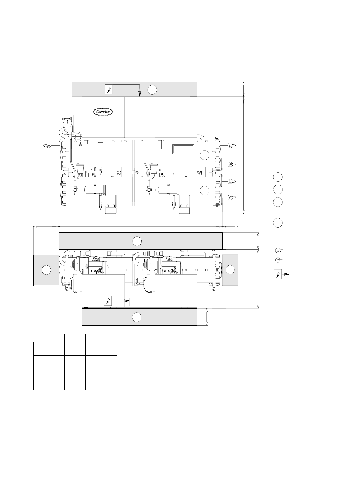
3 - DIMENSIONS, CLEARANCES, WEIGHT DISTRIBUTION
3.1 - 30HXC 080-190
30HXC080
30HXC090
30HXC100
30HXC110
3
1
2
D
A
3
600
C
1
Evaporator
Condenser
2
Clearances required
3
for operation and
maintenance
Clearances required for
E
500
4
heat exchanger tube
removal. Clearances D and
E can be either on the left
or on the right hand side.
Water inlet
4
30HXC080
30HXC090
30HXC100
30HXC110
30HXC120
30HXC130
30HXC140
30HXC155
30HXC175
30HXC190
A mm
2705
2705
3535
3550
B mm
950
950
950
950
C mm
1850
1900
1875
2000
D mm
2360
2360
3220
3220
E mm
2447
2462
1000
2504
1000 2650
2846
2861
1000
2956
2971
3283
1000
3438
Water outlet
4
B
3
kg
700
Power supply
kg: total operating weight
NOTE: Refer to the certified dimensional drawings supplied with the unit, when designing an installation.
5
Page 6
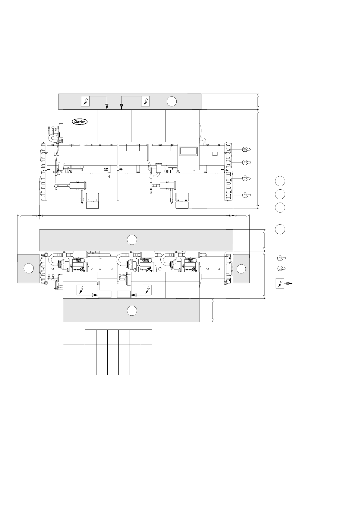
3 - DIMENSIONS, CLEARANCES, WEIGHT DISTRIBUTION (CONT.)
3.2 - 30HXC 200-375
3
600
C
1
Evaporator
2
Condenser
Clearances required
3
D
A
3
4
E
500
4
B
for operation and
maintenance
Clearances required for
4
heat exchanger tube
removal. Clearances D
and E can be either on
the left or on the right
hand side.
Water inlet
Water outlet
30HXC200
30HXC230
30HXC260
30HXC285
30HXC310
30HXC345
30HXC375
A mm
3975
3995
4490
B mm
980
980
980
C mm
2035
2116
2163
D mm
3620
3620
4120
3
kg
E mm
1000 4090
4705
4815
1000
4985
5760
5870
1000
6105
Power supply
kg: total operating weight
700
NOTE: Refer to the certified dimensional drawings supplied with the unit, when designing an installation.
6
Page 7
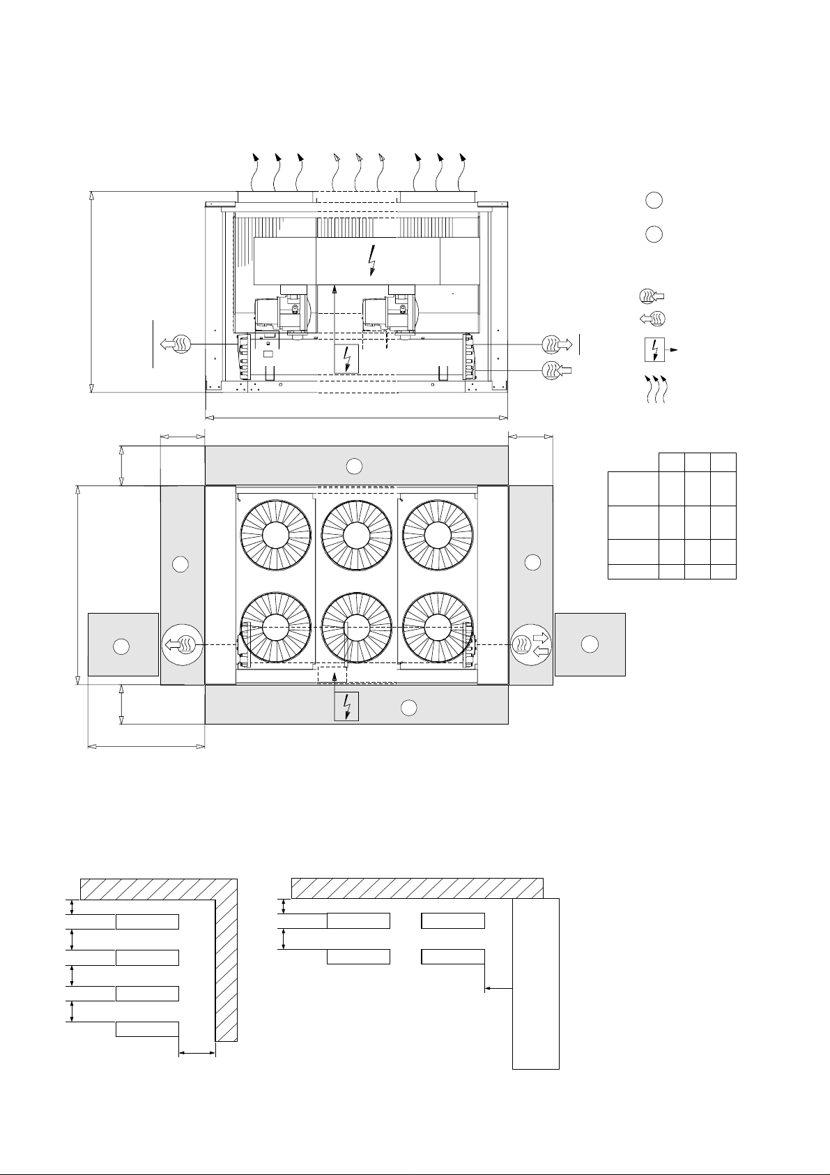
3 - DIMENSIONS, CLEARANCES, WEIGHT DISTRIBUTION (CONT.)
3.3 - 30GX 082-182
2287
30GX-082
30GX-092
30GX-102
30GX-112
30GX-122
30GX-132
30GX-152
30GX-162
30GX-182
Clearances required
1
for operation and
maintenance
Clearances required for
2
evaporator tube removal.
Clearances can be either
on the left or on the right
hand side.
Water inlet
Water outlet
Power supply
Air outlet - do not obstruct
1000
1830
1
2256
2
1830
B
Multiple chiller installation (see note 2)
A
kg: total operating weight
1000
B mm
2215
2045
2835
1820
kg
3116
3157
3172
3515
3531
3633
3920
3936
4853
1
30GX082
30GX092
30GX102
30GX112
30GX122
30GX132
30GX152
1
30GX162
30GX182
A mm
2970
3427
4342
5996
2
1
SOLID SURFACE AREA SOLID SURFACE AREA
Notes:
1830
2000
20002000
1830
2000
1525
1525
1. Unit must have clearances for air flow as follows:
Top: do not restrict in any way
2. In case of multiple chillers (up to four units), the
respective clearance between them should be increased
from 1830 to 2000 mm for the side space requirement.
3. Clearances sre required for cooler tube removal.
NOTE: Refer to the certified dimensional drawings supplied with the unit, when designing an installation.
7
Page 8
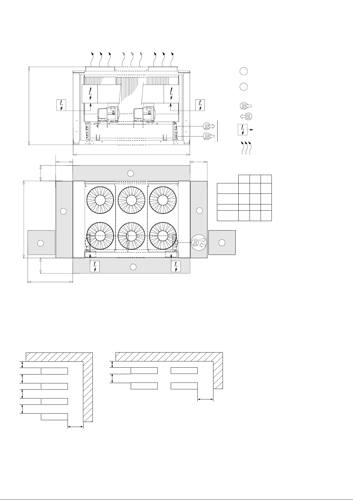
3 - DIMENSIONS, CLEARANCES, WEIGHT DISTRIBUTION (CONT.)
3.4 - 30GX 207-358
Clearances required
1
for operation and maintenance
Clearances required for evaporator tube
2
removal. Clearances can be either on the left
or on the right hand side.
2256
2287
1830
2
1830
1000
1
Water inlet
Water outlet
30GX-207
30GX-227
30GX-247
30GX-267
30GX-298
30GX-328
30GX-358
Power supply
Air outlet - do not obstruct
A
1000
1
30GX207
30GX227
30GX247
30GX267
1
1
30GX298
30GX328
30GX358
2
kg: total operating weight
B mm
A mm
2895
5996
2470
6911
2220
7826
1250
8741
kg
5540
5570
6134
6365
7354
7918
8124
B
Multiple chiller installation (see note 2)
SOLID SURFA CE AREA SOLID SURF A CE AREA
1830
2000
20002000
1525
1830
2000
1525
Notes:
1. Unit must have clearances for air flow as follows:
Top: do not restrict in any way
2. In case of multiple chillers (up to four units), the
respective clearance between them should be increased
from 1830 to 2000 mm for the side space requirement.
3. Clearances sre required for cooler tube removal.
NOTE: Refer to the certified dimensional drawings supplied with the unit, when designing an installation.
8
Page 9

4 - PHYSICAL DAT A 30HXC
30HXC 080 090 100 110 120 130 140 155 175 190 200 230 260 285 310 345 375
Net cooling capacity kW 292 321 352 389 426 464 514 550 607 663 716 822 918 996 1119 1222 1326
Operating weight kg 2447 2462 2504 2650 2846 2861 2956 2971 3283 3438 4090 4705 4815 4985 5760 5870 6105
Refrigerant HFC-134a
Circuit A/B kg 39/36 39/36 37/32 38/38 57/55 59/50 56/50 59/52 58/61 60/70 110/58 118/63 120/75 120/75 108/110 110/110 110/120
Oil Polyolester oil CARRIER SPEC: PP 47-32
Circuit A/B l 15/15 15/15 15/15 15/15 15/15 15/15 15/15 15/15 15/15 15/15 30/15 30/15 30/15 30/15 30/30 30/30 30/30
Compressors Hermetic twin-screw Power
Circ.A, nom. size per compressor** 39 46 46 56 56 66 80 80 80 80+ 66/56 80/56 80/80 80+/80+80/66 80/80 80+/80+
Circ.B, nom. size per compressor** 39 39 46 46 56 56 56 66 80 80+ 66 80 80 80+ 80/66 80/80 80+/80+
Control type PRO-DIALOG Plus control
Number of capacity steps 6666666666888810 10 10
Minimum capacity % 19 19 21 19 21 19 17 19 21 21 14 14 14 14 10 10 10
Evaporator Shell and tube type, with internally finned copper tubes
Net water volume l 65 65 73 87 81 81 91 9 1 109 109 140 165 181 181 203 229 229
Water connections Factory-supplied flat flange, to be welded on site
Inlet and outlet in. 444555555566668 8 8
Drain and vent (NPT) in. 3/8 3/8 3/8 3/8 3/8 3/8 3/8 3/8 3/8 3/8 3/8 3/8 3/8 3/8 3/8 3/8 3/8
Max. water-side operating pressure kPa 1000 1000 1000 1000 1000 1000 1000 1000 1000 1000 1000 1000 1000 1000 1000 1000 1000
Condensers Shell and tube type, with internally finned copper tubes
Net water volume l 58 58 58 58 92 92 110 110 132 132 162 208 208 208 251 251 251
Water connections Factory-supplied flat flange, to be welded on site
Inlet and outlet in. 555555556666668 8 8
Drain and vent (NPT) in. 3/8 3/8 3/8 3/8 3/8 3/8 3/8 3/8 3/8 3/8 3/8 3/8 3/8 3/8 3/8 3/8 3/8
Max. water-side operating pressure kPa 1000 1000 1000 1000 1000 1000 1000 1000 1000 1000 1000 1000 1000 1000 1000 1000 1000
3
* Standardised Eurovent conditions: evaporator entering/leaving water temperatures = 12°C/7°C, condenser water entering/leaving water temperatures = 30°C/35°C
Net cooling capacity: Gross cooling capacity minus the water pump heat against the internal evaporator pressure drop.
** The compressor size corresponds to the nominal capacity in tons (1 ton = 3.517 kW).
5 - ELECTRICAL DATA 30HXC
30HXC 080 090 100 110 120 130 140 155 175 190 200 230 260 285 310 345 375
Power circuit
Nominal power supply* V-ph-Hz 400-3-50
Voltage range V 360-440
Control circuit supply The control circuit is supplied via the factory-installed transformer
Nominal power input* kW 59 67 74 83 88 99 112 123 135 146 156 179 201 219 245 274 298
Nominal current drawn * A 98 111 124 139 148 166 186 204 226 242 259 291 335 367 408 456 498
Max. power input** kW 76 83 91 101 111 121 135 145 158 181 187 214 237 272 290 316 362
Circuit A kW - - - - - -----121135158181145158181
Circuit B kW - - - - - -----66797991145158181
Cosine phi, unit at full load 0.87 0.87 0.87 0.87 0.87 0.86 0.87 0.87 0.87 0.87 0.87 0.87 0.87 0.87 0.87 0.87 0.87
Max. current drawn (Un - 10%)*** A 138 152 166 184 202 221 245 264 288 330 341 389 432 495 528 576 660
Circuit A A - - - - - -----221245288330264288330
Circuit B A - - - - - -----120144144165264288330
Maximum current drawn (Un)*** A 125 138 151 167 184 201 223 240 262 300 310 354 393 450 480 524 600
Circuit A A - - - - - -----201223262300240262300
Circuit B A - - - - - -----109131131150240262300
Max. starting current, std. unit (Un)**** A 172 197 209 235 252 283 318 335 357 420 806 938 9 77 1156 1064 1108 1306
Circuit A*** A - - - - - -----6978078461006 824 846 1006
Circuit B*** A - - - - - -----6057157158568248461006
Max. starting current/max. current draw
ratio, unit 1.37 1.42 1.39 1.41 1.37 1.41 1.43 1.40 1.36 1.40 2.60 2.65 2.49 2.57 2.22 2.12 2.18
Max. starting current/max. current draw
ratio, circuit A - - - - - -----3.47 3.62 3.23 3.35 3.43 3.23 3.35
Max. starting current/max. current draw
ratio, circuit B - - - - - ---- 5.55 5.46 5.46 5.71 3.43 3.23 3.35
Max. starting current - reduced current
start (Un) **** A std. std. std. std. std. std. std. std. std. std. 601 643 682 760 769 813 910
Circuit A A std. std. std. std. std. std. std. std. std. std. 492 512 551 610 529 551 610
Circuit B A std. std. std. std. std. std. std. std. std. std. 330 370 370 385 529 551 610
Max.starting current - red. current start/
max. current draw ratio, unit std. std. std. std. std. std. std. std. std. std. 1.94 1.82 1.74 1.69 1.60 1.55 1.52
Circuit A std. std. std. std. std. std. std. std. std. std. 2.45 2.30 2.10 2.03 2.20 2.10 2.03
Circuit B std. std. std. std. std. std. std. std. std. std. 3.03 2.83 2.83 2.57 2.20 2.10 2.03
Three-phase short circuit holding current kA 25 25 25 25 25 25 25 25 25 25 N/A N/A N/A N/A N/A N/A N/A
Circuit A kA - - - - - ----.-25252525252525
Circuit B kA - - - - - -----15151515252525
Customer standby capacity, unit or circ. A,
for evaporatorwater pump connections† kW8 8 81111111515151515181830303030
* Standard Eurovent conditions: Evaporator entering/leaving water temperature 12°C and 7°C. Condenser entering/leaving water temperature 30°C/35°C.
** Power input, compressor, at unit operating limits (evaporator wa ter entering/leaving temperature = 15°C/10°C, condenser entering/leaving water temperature = 40°C/45°C) and a nominal
voltage of 400 V (data given on the unit name plate).
*** Maximum unit operating current at maximum unit power input.
**** Maximum instantaneous starting current (maximum operating current of the smallest compressor(s) + locked rotor current or r educed starting current of the largest compressor)
† Current and power inputs not included in the values above.
N/A Not available
9
Page 10

Compressors
Reference Size I nom. MHA LRA LRA (Y) LRA (S) 1 cp. LRA (S) 2 cp.
06NW2146S7N 39 48 69 344 109 125 06NW2174S7N 46 58 83 423 134 154 06NW2209S7N 56 71 101 506 160 260 350
06NW2250S7N 66 87 120 605 191 330 400
06NW2300S5N 80 104 144 715 226 370 420
06NW2300S5E 80+ 1 11 165 856 270 385 460
Legend:
06NW - Compressor for water-cooled units
N - Non-economized compressor
E - Economized compressor
INOM - A v erage current dra w of the compressor at Eurovent conditions
MHA - Must hold amperes (maximum operating current) at 360 V
LRA - Locked rotor current with across-the-line start
LRA (Y) - Locked rotor current at reduced current (star/delta start-up mode)
LRA (S) 1 cp. - Start-up with reduced current with electronic starter (start-up duration 3 seconds max.) for one compressor per circuit
LRA (S) 2 cp. - Start-up with reduced current with electronic starter (start-up duration 3 seconds max.) for two compressors per circuit
10
Page 11

6 - ELECTRICAL DATA FOR UNITS WITH HIGH CONDENSING TEMPERATURES
30HXC 150 and 150A Options
30HXC 080 090 100 110 120 130 140 155 175 190 200 230 260 285 310 345 375
Power circuit
Nominal power supply (Un) V-ph-Hz 400-3-50
Voltage range V 360-440
Control circuit supply The control circuit is supplied via the factory-installed transformer
Max. power input** kW 104 117 131 145 159 174 194 211 230 263 271 310 345 395 422 460 526
Circuit A kW - - - - - -----175195230263211230263
Circuit B kW - - - - - -----96115115132211230263
Max. current drawn (Un - 10%)*** A 190 215 240 265 290 320 355 385 420 480 495 564 630 720 770 840 960
Circuit A A - - - - - -----320355420480385420480
Circuit B A - - - - - -----175210210240385420480
Maximum current drawn (Un)*** A 173 195 218 241 264 291 323 350 382 436 450 514 573 655 700 764 873
Circuit A A - - - - - -----291323382436350382436
Circuit B A - - - - - -----159191191218350382436
Max. starting current, std. unit (Un)**** A 277 312 335 379 402 435 519 546 578 618 1251 1549 1608 1701 1735 1799 1920
Circuit A**** A - - - - - -----1092 1358 1417 1483 1385 1417 1483
Circuit B**** A - - - - - -----9601226 1226 1265 1385 1417 1483
Max. starting current/max. current draw
ratio, unit 1.61 1.60 1.54 1.57 1.52 1.49 1.61 1.56 1.51 1.42 2.78 3.02 2.81 2.60 2.48 2.36 2.20
Max. starting current/max. current draw
ratio, circuit A - - - - - -----3.75 4.21 3.71 3.40 3.96 3.71 3.40
Max. starting current/max. current draw
ratio, circuit B - - - - - ---- 6.03 6.42 6.42 5.80 3.96 3.71 3.40
Max. starting current - reduced current
start (Un)**** A std. std. std. std. std. std. std. std. std. std. N/A N/A N/A N/A N/A N/A N/A
Three-phase short circuit holding current kA 25 25 25 25 25 25 25 25 25 25 N/A N/A N/A N/A N/A N/A N/A
Circuit A kA - - - - - ----.-25252525252525
Circuit B kA - - - - - -----15151515252525
Customer standby capacity, unit or circ. A,
for evaporator water pump connections† kW8 8 81111111515151515181830303030
** Power input, compressor, at unit operating limits (evaporator wa ter entering/leaving temperature = 15°C/10°C, condenser entering/leaving water temperature = 40°C/45°C) and a nominal
voltage of 400 V (data given on the unit name plate).
*** Maximum unit operating current at maximum unit power input.
**** Maximum instantaneous starting current (maximum operating current of the smallest compressor(s) + locked rotor current or r educed starting current of the largest compressor)
† Current and power inputs not included in the values above
N/A Not available
The 30HXC 080-375 units for high condensing temperatures
are directly derived from the standard models. Their application range is the same as that of the standard units, but permits
Technical information
All information is identical to that of the standard 30HXC
units, except for the following paragraphs.
operation at condenser leaving water temperatures up to 63°C.
The PRO-DIALOG control offers all the advantages of the
standard units, plus control of the condenser leaving water
temperature.
The main modifications are:
- Use of 30GX compressors
- Modification of electrical components to operate with
compressors for high condensing temperatures.
- Modification of heat exchangers to meet pressure code
requirements (if necessary).
Option 150
These units are designed for traditional applications for watercooled units, but for higher condender leaving water
temperatures than 45°C.
Like the standard units they are equipped with condenser
Selection
There are no nominal conditions for this unit type. The
selection is made using the current electronic catalogue.
Dimensions
These are identical to those of the standard 30HXC units. The
only difference is in the diameter of the incoming field wiring
connection, described in the chapter “Recommended selection”.
Refer to the dimensional drawings for these units, before
proceeding with the wiring.
Compressor
See 30GX compressor table.
Options and accessories
All options available for the standard 30HXC units are compa-
tible, except:
entering and leaving water sensors, installed on the piping.
It is possible to control the machine at the condenser water
outlet, requiring a factory configuration change and the use of
a heating/cooling inlet reversing device.
Option 150A
These units are designed for water-to-water heat pumps.
They are factory configured as heat pumps (heating/cooling
control as a function of the remote reversing device). The
condenser incorporates thermal insulation that is identical to
that of the evaporator.
Option 5, brine unit Special unit
Option 25, soft start, 30HXC 200-375 units Not available
Attention:
If units have two different operating modes - one with high
condensing temperature and the other with low condensing
temperature - and the transition is made with the unit in
operation, the temperature must not vary by more than 3 K
per minute. In cases where this is not possible, it is recom-
mended to go through a unit start/stop switch (remote start/
stop available for standard units).
11
Page 12
7 - PHYSICAL DAT A 30GX
30GX 082 092 102 112 122 132 152 162 182 207 227 247 267 298 328 358
Net cooling capacity* kW 285 309 332 388 417 450 505 536 602 687 744 810 910 1003 1103 1207
Operating weight kg 3116 3157 3172 3515 3531 3633 3920 3936 4853 5540 5570 6134 6365 7354 7918 8124
Refrigerant charge HFC-134a
Circuit A/B kg 55/55 58/50 54/53 55/53 60/57 63/60 75/69 75/75 80/80 130/85 130/85 155/98 170/104 162/150 162/165 175/175
Oil Polyolester oil CARRIER SPEC: PP 47-32
Circuit A/B l 20/20 20/20 20/20 20/20 20/20 20/20 20/20 20/20 20/20 40/20 40/20 40/20 40/20 40/40 40/40 40/40
Compressors Hermetic twin-screw Power
Circ.A, nom. size per compressor** 46 46 56 56 66 66 80 80 80+ 66/56 80/66 80/80 80+/80+ 80/80 80/80 80+/80+
Circ.B, nom. size per compressor** 39 46 46 56 56 66 66 80 80+ 80 80 80 80+ 66/66 80/802 80+/80+
Control type PRO-DIALOG Plus control
Number of capacity steps 6666666668888 1010 10
Minimum capacity % 19 21 19 21 19 21 19 21 21 16 14 14 14 9 10 10
Evaporator Shell and tube type, with internally finned copper tubes
Net water volume l 65 73 73 87 87 101 91 91 109 140 140 165 181 203 229 229
Water connections Factory-supplied flat flange, to be welded on site
Inlet and outlet in. 4445555556666 8 8 8
Drain and vent (NPT) in. 3/8 3/8 3/8 3/8 3/8 3/8 3/8 3/8 3/8 3/8 3/8 3/8 3/8 3/8 3/8 3/8
Maximum water-side operating pressure kPa 1000 1000 1000 1000 1000 1000 1000 1000 1000 1000 1000 1000 1000 1000 1000 1000
Condensers Copper tubes and aluminium fins
Fans Axial FLYING BIRD 2 fan with rotating shroud
Quantity 444666888101012121416 16
Speed r/s 15.8 15.8 15.8 15.8 15.8 15.8 15.8 15.8 15.8 15.8 15.8 15.8 15.8 15.8 15.8 15.8
Total air flow l/s 21110 21110 21110 31660 31660 31660 42220 42220 42220 52770 52770 63330 63330 73880 84440 84440
3
* Standardised Eurovent conditions: evaporator entering/leaving water temperatures = 12°C/7°C, outside air temperature = 35°C
Net cooling capacity: Gross cooling capacity minus the water pump heat against the internal evaporator pressure drop.
** The compressor size corresponds to the nominal capacity in tons (1 ton = 3.517 kW).
8 - ELECTRICAL DATA 30GX
30GX 082 092 102 112 122 132 152 162 182 207 227 247 267 298 328 358
Power circuit
Nominal power supply V-ph-Hz 400-3-50
Voltage range V 360-440
Control circuit supply The control circuit is supplied via the factory-installed transformer
Nominal power input* kW 98 109 123 133 150 166 179 196 214 246 281 292 332 364 394 449
Nominal current drawn * A 180 200 223 256 273 290 326 352 388 449 492 528 582 642 704 776
Maximum power input** kW 127 141 154 175 191 207 234 253 286 319 355 380 429 462 506 572
Circuit A kW - - - - - - - - - 193 228 253 286 253 253 286
Circuit B kW - - - - - - - - - 127 127 127 143 209 253 286
Cosine phi, unit at full load 0.85 0.85 0.85 0.85 0.85 0.85 0.86 0.86 0.86 0.86 0.86 0.86 0.86 0.86 0.86 0.86
Maximum current drawn (Un - 10%)*** A 237 262 287 323 353 383 429 464 524 585 650 696 786 847 928 1048
Circuit A A - - - - - - - - - 353 418 464 524 464 464 524
Circuit B A - - - - - - - - - 232 232 232 262 383 464 524
Maximum current drawn (Un)*** A 217 240 263 297 324 351 394 426 480 537 596 639 721 777 852 961
Circuit A A - - - - - - - - - 324 383 426 480 426 426 480
Circuit B A - - - - - - - - - 213 213 213 240 351 426 480
Max. starting current, standard unit**** (Un) A 334 357 401 435 468 495 590 622 662 1338 1631 1674 1767 1812 1887 2008
Circuit A*** A - - - - - - - - - 1125 1418 1461 1527 1461 1461 1527
Circuit B*** A - - - - - - - - - 1248 1248 1248 1287 1152 1461 1527
Max. starting current/max. current draw ratio,
unit 1.54 1.49 1.53 1.47 1.44 1.41 1.50 1.46 1.38 2.49 2.74 2.62 2.45 2.33 2.22 2.09
Max. starting current/max. current draw ratio,
circuit A - - - - - - - - - 3.47 3.70 3.43 3.18 3.43 3.43 3.18
Max. starting current/max. current draw ratio,
circuit B - - - - - - - - - 5.86 5.86 5.86 5.36 3.28 3.43 3.18
Max. starting current - reduced current
start**** (Un) A std. std. std. std. std. std. std. std. std. 878 955 998 1102 1136 1211 1343
Circuit A A std. std. std. std. std. std. std. std. std. 665 742 785 862 785 785 862
Circuit B A std. std. std. std. std. std. std. std. std. 572 572 572 622 692 785 862
Max.starting current - red. current start/max.
current draw ratio, unit std. std. std. std. std. std. std. std. std. 1.64 1.60 1.56 1.53 1.46 1.42 1.40
Circuit A std. std. std. std. std. std. std. std. std. 2.05 1.94 1.84 1.79 1.84 1.84 1.79
Circuit B std. std. std. std. std. std. std. std. std. 2.69 2.69 2.69 2.39 1.97 1.84 1.79
Three-phase short-circuit holding current kA 25 25 25 25 25 2 5 25 25 25 N/A N/A N/A N/A N/A N/A N/A
Circuit A kA - - - - - - - - -. 25 25 25 25 25 25 25
Circuit B kA - - - - - - - - - 25 25 25 25 25 25 25
Customer standby capacity, unit or circuit A,
for evaporator water pump connections † kW 4445.55.55.57.57.57.57.5999151515
* Standard Eurovent conditions: Evaporator entering/leaving water temperature 12°C and 7°C. Outdoor air temperature 35°C.
** Power input, compressor and fan, at unit operating limits (evaporator water entering/leaving temperature = 15°C/10°C, outdoor air temperature = 46°C) and a nominal voltage of 400 V (data
given on the unit name plate).
*** Maximum unit operating current at maximum unit power input.
**** Maximum instantaneous starting current (maximum operating current of the smallest compressor(s) + fan current + locked rotor current or reduced starting current of the largest
compressor).
† Current and power inputs not included in the values above
N/A Not advailable
12
Page 13
Compressors
Reference Size I nom. MHA LRA LRA (Y) LRA (S) 1 cp. LRA (S) 2 cp.
06NA2146S7N 39 70 95 605 191 220 06NA2174S7N 46 90 120 715 226 260 06NA2209S7N 56 113 145 856 270 330 420
06NA2250S7N 66 130 175 960 303 380 500
06NA2300S5N 80 156 210 1226 387 445 550
06NA2300S5E 80+ 174 240 1265 400 460 600
Legend:
06NA - Compressor for air-cooled units
N - Non-economized compressor
E - Economized compressor
INOM - A v erage current dr aw of the compressor at Euro v ent conditions
MHA - Must hold amperes (maximum operating current) at 360 V
LRA - Locked rotor current with across-the-line start
LRA (Y) - Locked rotor current at reduced current (star/delta start-up mode)
LRA (S) 1 cp. - Start-up with reduced current with electronic starter (start-up duration 3 seconds max.) for one compressor per circuit
LRA (S) 2 cp. - Start-up with reduced current with electronic starter (start-up duration 3 seconds max.) for two compressors per circuit
9 - APPLICATION DATA
9.1 - Unit operating range
Evaporator Minimum Maximum
Evaporator entering water temperature °C 6.8* 21
Evaporator leaving water temperature °C 4** 15
Condenser (water-cooled) Minimum Maximum
Condenser entering water temperature °C 20*** 42
Condenser leaving water temperature °C 25 45
Outside ambient operating temperature 30HXC °C 6 40
Condenser (air-cooled) Minimum Maximum
Outdoor ambient operating temperature °C 0 46
Available static pressure kPa 0
Notes:
* For application requiring operation at less than 6.8°C, contact Carrier s.a. for unit
selection using the Carrier electronic catalog.
** For application requiring operation at less than 4°C, the units require the use of
antifreeze.
*** Water-cooled units (30HXC) operating at full load and below 20°C condenser entering
water temperature require the use of a head pressure control with analogue water control
valves (see paragraph on head pressure control).
In temporary operating modes (start-up and at part load) the unit can operate with a
condenser entering air temperature of 13°C.
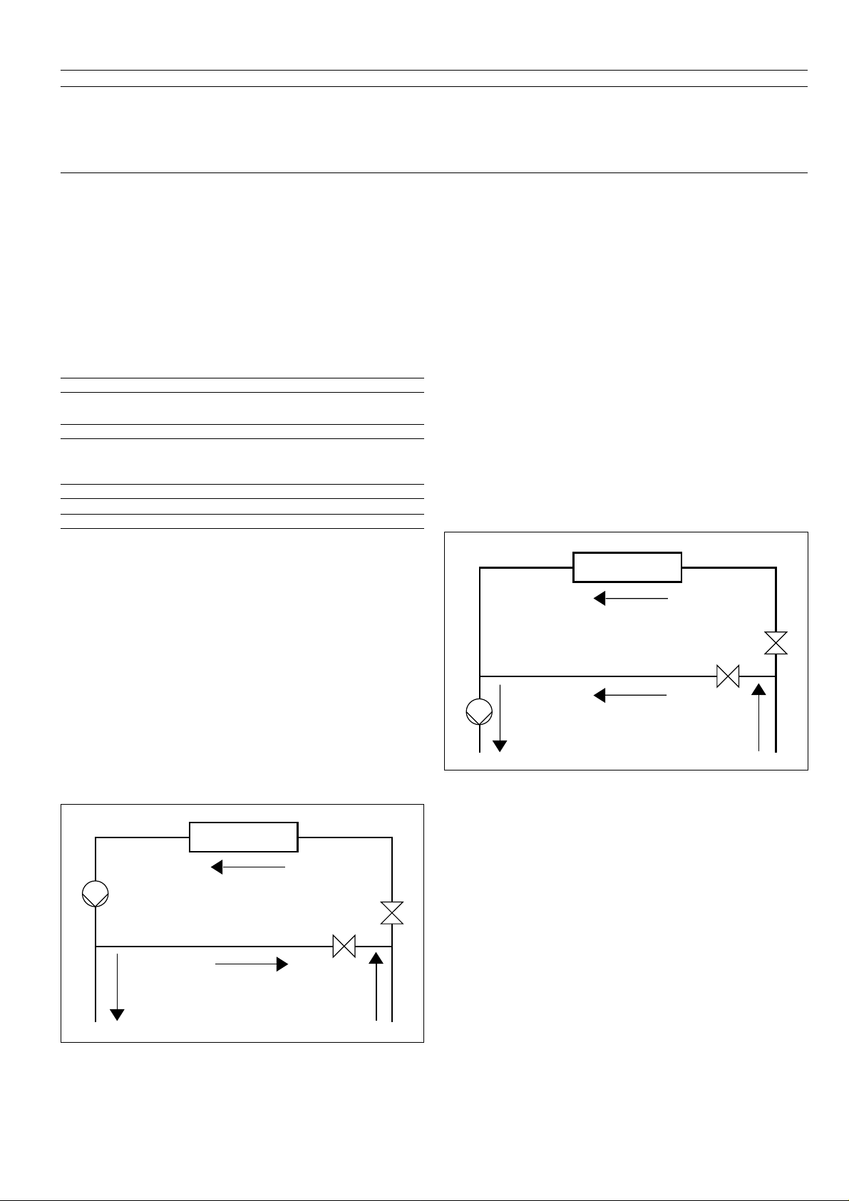
9.2 - Minimum chilled water flow
The minimum chilled water flow is shown in the table on the
next page. If the flow is less than this, the evaporator flow can
be recirculated, as shown in the diagram. The temperature of
the mixture leaving the evaporator must never be less than
2.8 K lower than the chilled water entering temperature.
9.3 - Maximum chilled water flow
The maximum chilled water flow is limited by the maximum
permitted pressure drop in the evaporator. It is provided in the
table on the next page. If the flow exceeds the maximum value,
two solutions are possible:
a - Select a non-standard evaporator with one water pass less
which will allow a higher maximum water flow rate.
b - Bypass the evaporator as shown in the diagram to obtain a
highter temperature difference with a lower evaporator flow
rate.
EVAPORATOR
BYP ASS
FOR MAXIMUM CHILLED WATER FLOW RATE
EVAPORATOR
RECIRCULATION
FOR MINIMUM CHILLED WATER FLOW RATE
13
Page 14
9.4 - Variable flow evaporator
9.6 - Cooler flow rate (l/s)
Variable evaporator flow can be used in standard 30HXC and
30GX chillers. The chillers maintain a constant leaving water
temperature under all flow conditions. For this to happen, the
minimum flow rate must be higher than the minimum flow
given in the table of permissible flow rates and must not vary
by more than 10% per minute. If the flow rate changes more
rapidly, the system should contain a minimum of 6.5 liters of
water per kW instead of 3.25 l/kW.
9.5 - System minimum water volume
Whichever the system, the water loop minimum capacity is
given by the formula:
Capacity = Cap (kW) x N Liters
Application N
Normal air conditioning 3.25
Process type cooling 6.5
Where Cap is the nominal system cooling capacity (kW) at the
nominal operating conditions of the installation.
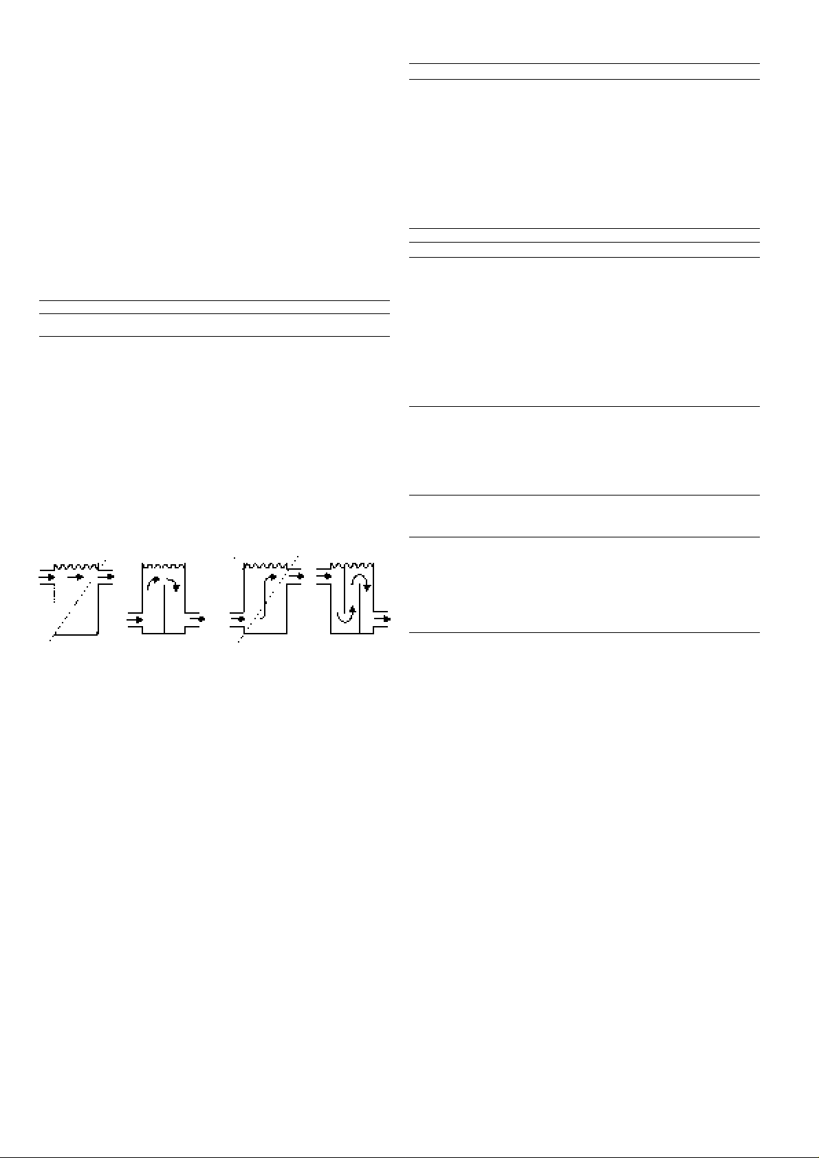
This volume is necessary for stable operation and accurate
temperature control.
It is often necessary to add a buffer water tank to the circuit in
order to achieve the required volume. The tank must itself be
internally baffled in order to ensure proper mixing of the liquid
(water or brine). Refer to the examples below.
NOTE: The compressor must not restart more than 6 times in
an hour.
30HXC Min.* Max.**
080-090 5.7 22.7
100 6.0 24.1
110 6.9 27.5
120-130 8.3 33.0
140-155 10.0 39.5
175-190 10.7 42.7
200 13.4 53.7
230 13.4 60.6
260-285 17.0 68.1
310 19.4 77.8
345-375 21.3 85.3
30GX Min.* Max.**
082 5.7 22.7
092-102 6.0 24.1
112-122 6.9 27.5
132 8.4 33.7
152-162 10.0 39.9
182 10.7 42.7
207-227 13.4 53.7
247 15.1 60.6
267 17.0 68.1
298 19.4 77.8
328-358 21.3 85.3
*Based on a water velocity of 0.9 m/s.
** Based on a water velocity of 3.6 m/s.
9.7 - Condenser flow rate (l/s)
30HXC Min.* Max.**
Closed Open
loop loop
080-110 2.5 7.5 29.9
120-130 3.1 9.3 37.3
140-155 3.8 11.4 45.5
175-190 4.6 13.8 55.2
200 5.0 14.9 59.6
230-285 6.7 20.1 80.3
310-375 7.3 22.0 88.0
BAD
GOOD BAD GOOD
*Based on a water velocity of 0.3 m/s in a closed loop and 0.9 m/s in an open
loop.
** Based on a water velocity of 3.6 m/s.
14
Page 15
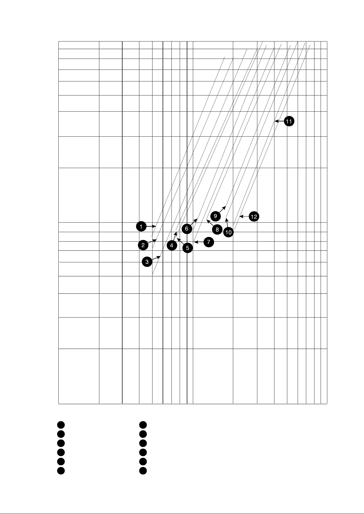
9.8 - Evaporator pressure drop curve
100
Pressure drop, kPa
10
1
1
1
30HXC 080-090/30GX 082
2
30HXC 100/30GX 092-102
3
30HXC 110/30GX 112-122
4
30GX 132
5
30HXC 120-130
6
30HXC 140-155/30GX 152-162
7
30HXC 175-190/30GX 182
8
30HXC 200/30GX 207-227
9
30HXC 230/30GX 247
10
30HXC 260-285/30GX 267
11
30HXC 310/30GX 298
12
30HXC 345-375/30GX 328-358
10
100
Water flow rate, l/s
15
Page 16
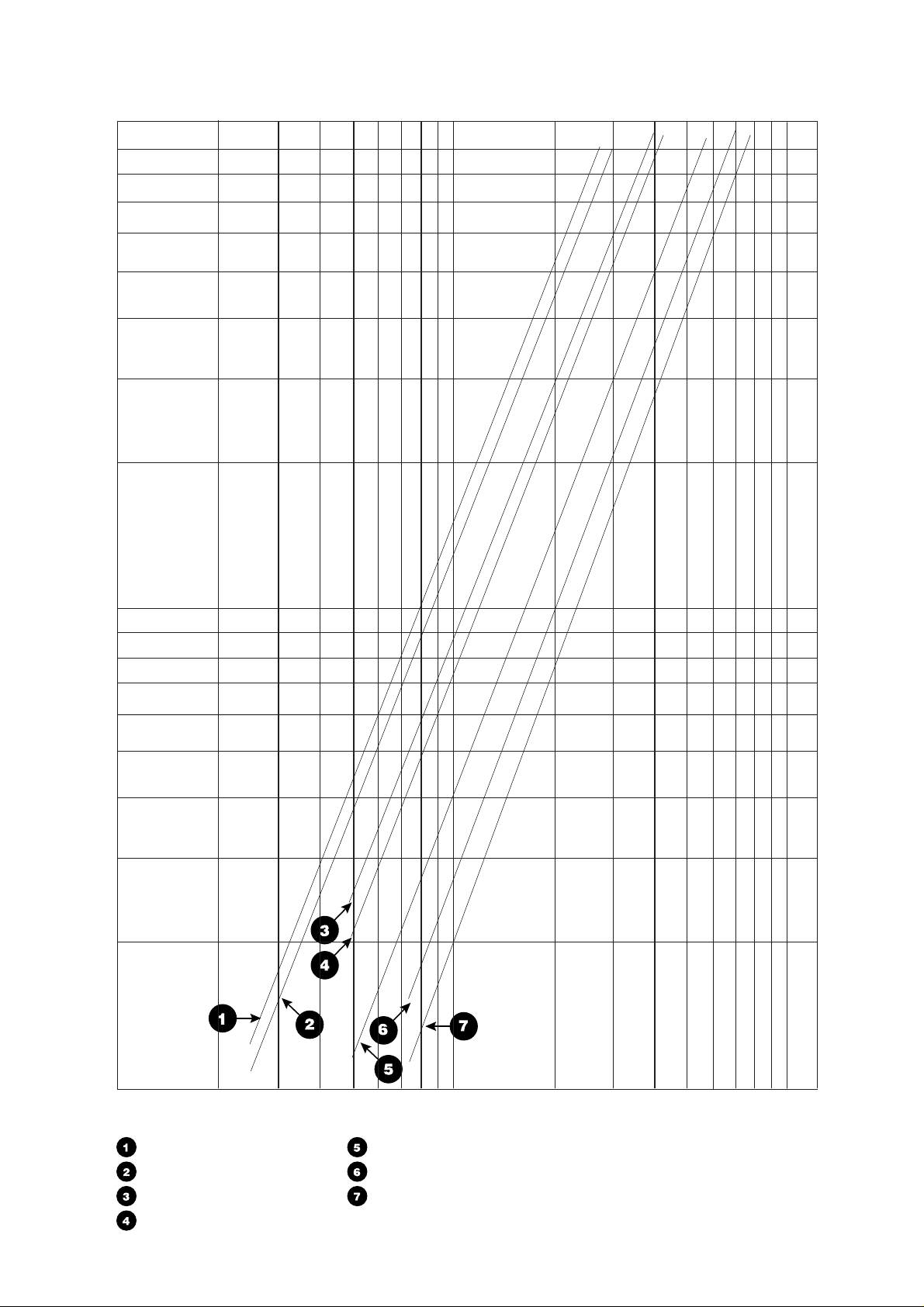
9.9 - Condenser pressure drop curve
100
Pressure drop, kPa
10
16
1
1
30HXC 080-090-100-110
30HXC 120-130
30HXC 140-155
30HXC 175-190
10
Water flow rate, l/s
30HXC 200
30HXC 230-260-285
30HXC 310-345-375
100
Page 17
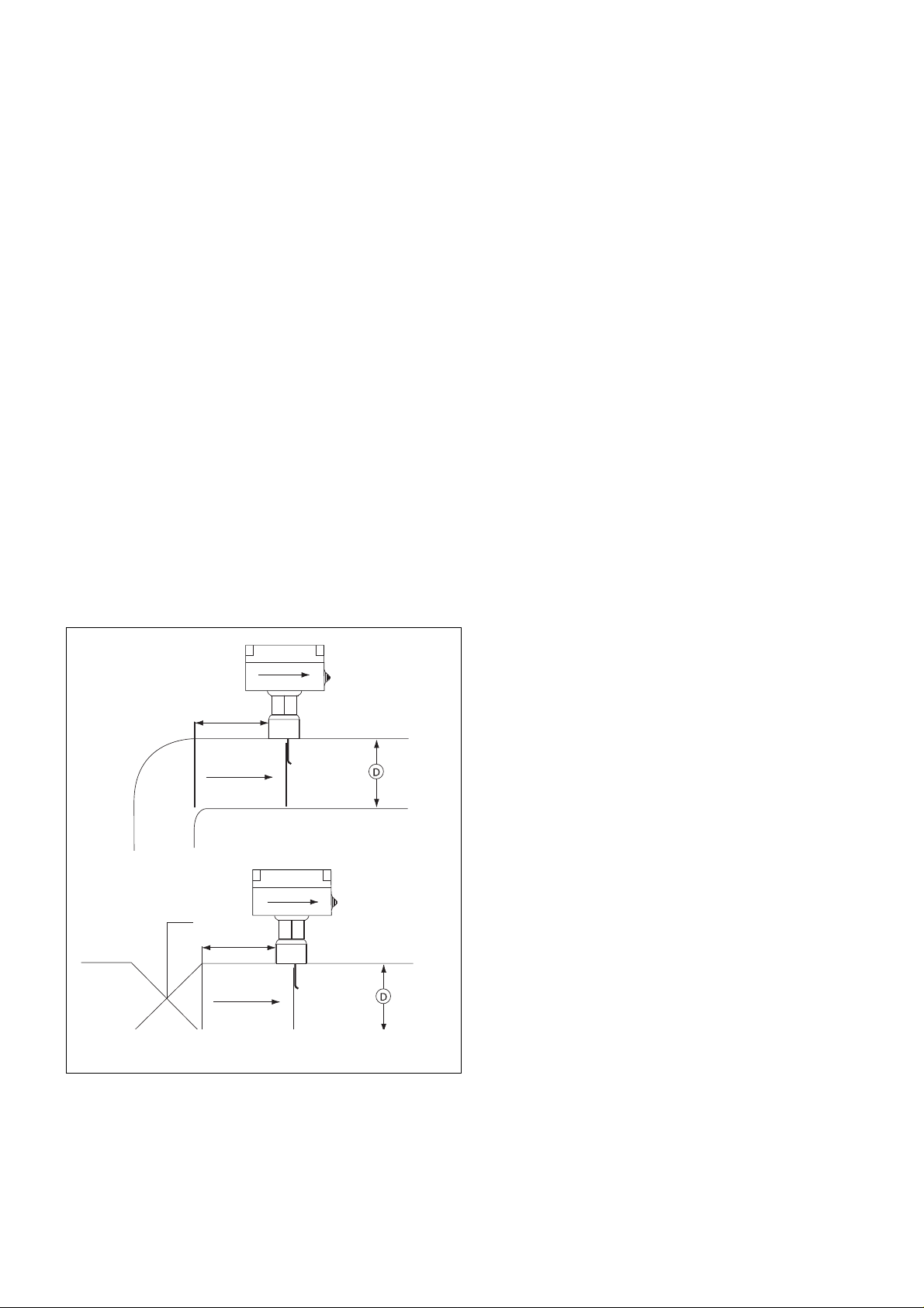
9.10 - Flow controllers
10 - INSTALLATION
9.10.1 - Cooler flow switch and chilled water pump interlock
IMPORTANT
It is mandatory to install cooler flow switch and also to
connect chilled water pump interlock on 30HXC and 30GX.
Failure to this instruction will void Carrier guarantee.
The cooler flow switch controller is factory supplied and wired
on 30HXC and 30GX units.
Follow the manufacturer instruction for installation.
The flow switch may be mounted in a horizontal pipe or a
vertical pipe with upward liquid flow. It should not be used
when liquid flow is downwards.
Mount in a section of pipe where there is a straight run of at
least five pipe diameters on each side of the flow switch. Do
not locate adjacent to valves, elbows or orifices. The paddle
must never touch the pipe or any restriction in the pipe. Screw
the flow switch in position so the flat part of the paddle is at
right angles to the flow. The arrows on the cover and in the
bottom, inside the case, must point in the direction of the flow.
The switch should be mounted so that the terminals are
FLOW
accessible for easy wiring.
Terminals 34 and 35 are provided for field installation of a
chilled water pump interlock (auxiliary contact of chilled water
pump contactor).
(Pipe connection: 1" NPT)
10.1 - Check equipment received
• Inspect the unit for damage or missing parts. If damage is
detected, or if shipment is incomplete, immediately file a
claim with the shipping company.
• Confirm that the unit received is the one ordered.
Compare the nameplate data with the order.
• Confirm that all accessories ordered for on-site installation
have been delivered, and are complete and undamaged.
• Do not store units in an area exposed to weather because of
sensitive control mechanism and electronic devices.
10.2 - Moving and siting the unit
10.2.1 - Moving
Do not remove skids, pallets or protective packaging until the
unit is in its final position. Move the chiller using tubes or
rollers, or lift it, using slings of the correct capacity.
CAUTION (30HXC)
Only use slings at the designated lifting points which are
marked on the unit, on the top of the cooler heat exchanger.
Rigging from the bottom of the heat exchanger will cause the
unit to be lifted unsafely. Personal injury or damage to the
unit may occur. Follow the rigging instruction given on the
certified dimensional drawing supplied with the unit.
10.2.2 - Siting
Always refer to the chapter "Dimensions and clearances" to
confirm that there is adequate space for all connections and
service operation. For the center of gravity coordinates, the
position of the unit mounting holes, and the weight distribution
points, refer to the certified dimensional drawing supplied with
the unit.
5 x D MIN.
5 x D mini
FLOW
5 x D MIN.
5 x D mini
FLOW
9.10.2 - Condenser flow switch (30HXC)
The condenser flow switch is a field-installed device.
We recommend that these chillers be installed either in a
basement or at ground level. If one is to be installed above
ground level, first check that the permissible floor loading is
adequate and that the floor is strong enough and level. If
necessary, strengthen and level the floor.
With the chiller in its final location remove the skids, and other
devices used to aid in moving it. Level the unit using a spirit
level, and bolt the unit to the floor or plinth. Operation of these
units may be impaired if they are not level and not securely
fixed to their mountings. If required use isolation pads under
the unit to aid in vibration isolation.
17
Page 18
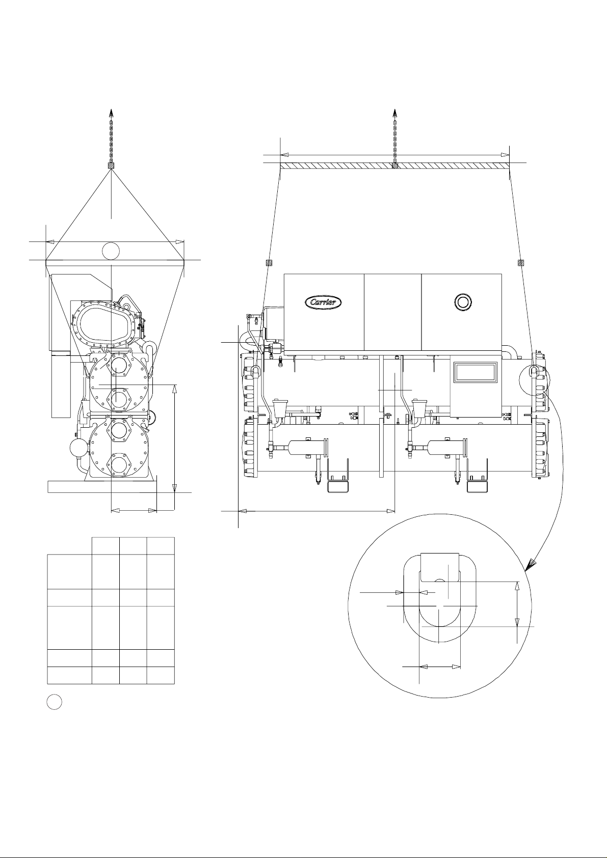
11 - LIFTING INSTRUCTIONS
11.1 - 30HXC 080-190
This diagram is shown for information only. Refer to “certified
drawings”.
1200 mm mini.
1
2000 mm mini.
E
N
O
Z
O
O
R
E
R-134a
Z
D
E
P
L
E
T
I
O
N
30HXC080
30HXC090
30HXC100
30HXC110
30HXC120
30HXC130
30HXC140
30HXC155
30HXC175
EXCEPT 30HXC 190
1
X mm
1345
1368
1731
1703
397
386
398 955170530HXC190
Z
Y
Z mmY mm
903402
X
Ø 13.5
935
39
879392
947
36
NOTE
When all lifting and positioning operations are finished, it is recommended to touch up all surfaces where paint has been
removed on lifting lugs.
18
Page 19
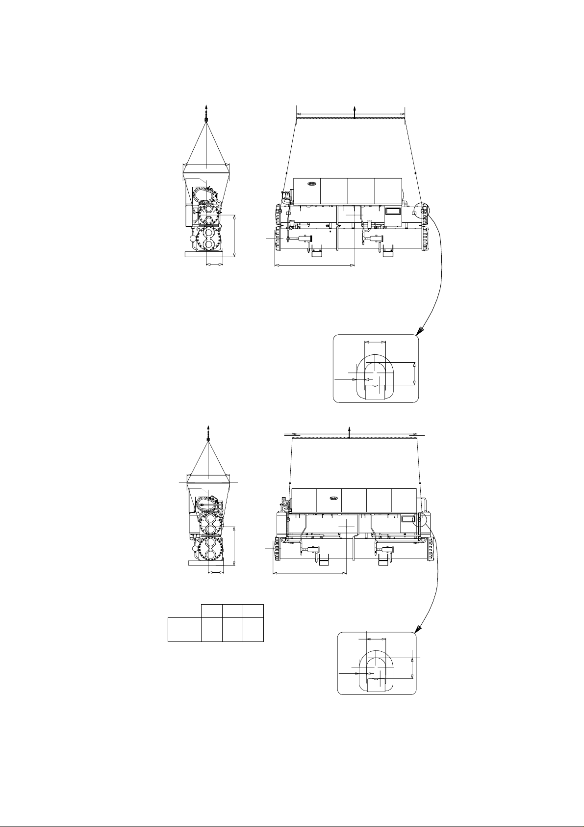
11 - LIFTING INSTRUCTIONS (CONT.)
11.2 - 30HXC 200-285
This diagram is shown for information only. Refer to “certified
drawings”.
1200 mm min.
1035
2800 mm min.
11.3 - 30HXC 310-375
425
1200 mm min.
2075
Ø 13.5
36
39
3500 mm min.
Z
30HXC310
30HXC345
30HXC375
X mm
2195
2195
2205
Y
Z mmY mm
425
1085
425
1085
435
1025
X
36
Ø 13.5
39
NOTE
When all lifting and positioning operations are finished, it is recommended to touch up all surfaces where paint has been
removed on lifting lugs.
19
Page 20
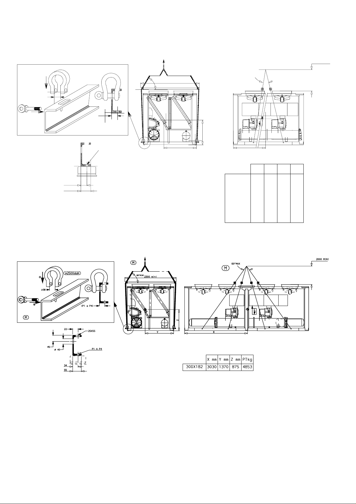
11 - LIFTING INSTRUCTIONS (CONT.)
11.4 - 30GX 082-162
This diagram is shown for information only. Refer to “certified
drawings”.
2000 mm min.
1
38
2
M
11.5 - 30GX 182
2.5 T
34
55
(P1 a P4)
P1 a P4
60@27MINI
2300 mm min.
60 MAX
Z
Y
30GX082
30GX092
30GX102
30GX112
30GX122
30GX132
30GX152
30GX162
X
X mm
1440
1440
1440
1650
1650
1650
2155
2155
Y mm
1460
1460
1460
1460
1460
1460
1430
1430
Z mm
900
900
900
900
900
900
900
900
PTkg
3115
3156
3170
3574
3527
3634
3938
3954
NOTE
When all lifting and positioning operations are finished, it is recommended to touch up all surfaces where paint has been
removed on lifting lug
20
Page 21
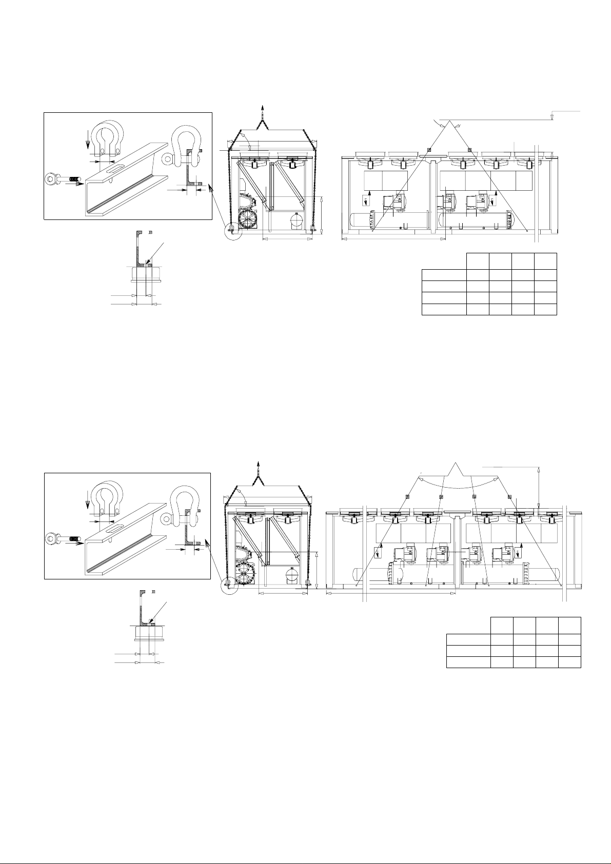
11 - LIFTING INSTRUCTIONS (CONT.)
11.6 - 30GX 207-267
This diagram is shown for information only. Refer to “certified
drawings”..
38
1
2.5 T
60 MINI
2300 mm min.
60 MAX
2000 mm min.
2
M
34
55
11.7 - 30GX 298-358
1
2.5 T
(P1 a P6)
P1 a P6
60 mm mini.
2300 mm min.
Z
Y
X
PTkg
Z mm
Y mm
X mm
30GX207
30GX227
30GX247
30GX267
2870
2870
3320
3300
60
1440
1440
1430
1420
890
890
927
886
5536
5572
6131
6363
in.
m
m
2800 m
38
2
M
(P1 a P6)
Z
P1 a P6
34
55
Y
X
Z mm
Y mm
X mm
30GX298
30GX328
30GX358
3630
4360
4360
1420
1455
1445
890
920
930
NOTE
When all lifting and positioning operations are finished, it is recommended to touch up all surfaces where paint has been
removed on lifting lugs.
PTkg
7353
7840
8045
21
Page 22
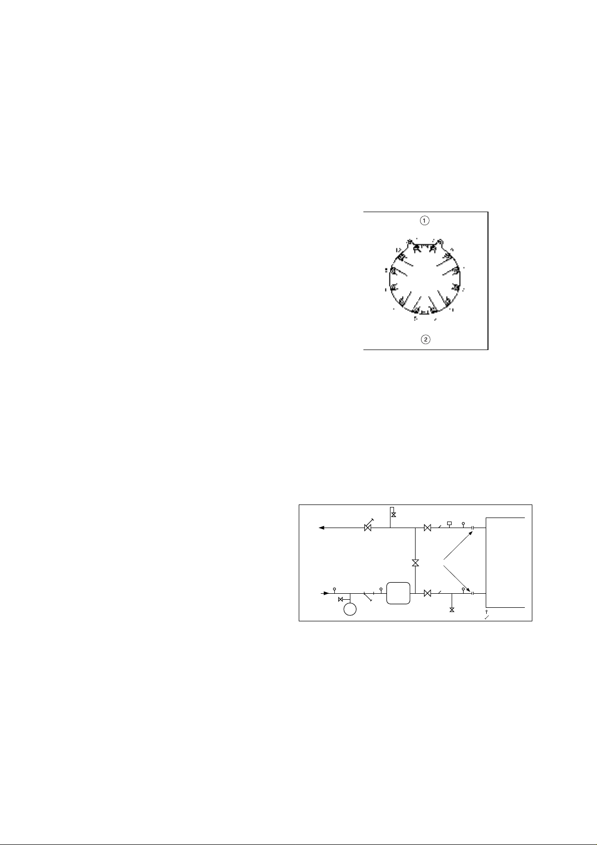
11.8 - Piping connections
Refer to the certified dimensional drawings for the sizes and
positions of all water inlet and outlet connections. The water
pipes must not transmit any radial or axial force to the heat
exchangers or any vibration to the pipework or building.
The water supply must be analysed and appropriate filtering,
treatment, control devices, isolation and bleed valves and
circuits built in, as necessary. Consult either a water treatment
specialist or appropriate literature on the subject.
11.8.1 - Operating precautions
The water circuit should be designed to have the least number
of elbows and horizontal pipe runs at different levels. The
following basic checks should be done (see also the illustration
of a typical hydraulic circuit below).
• Note the water inlets and outlets of the heat exchangers.
• Install manual or automatic air purge valves at all high points
in the water circuit.
• Use an expansion chamber or an expansion/relief valve to
maintain pressure in the system.
• Install water thermometers and pressure gauges in both the
entering and leaving water connections close to the
evaporator.
• Install drain valves at all low points to allow the whole
circuit to be drained. Connect a stop valve in the drain line
before operating the chiller.
• Install stop valves and pressure gauges, close to the
evaporator, in the entering and leaving water lines.
• Install cooler flow switch.
• Use flexible connections to reduce the transmission of
vibration to the pipework.
• Insulate all pipework, after testing for leaks, both to reduce
thermal leaks and to prevent condensation.
• Cover the insulation with a vapour barrier.
11.8.2 - Evaporator and condenser connections
The evaporator and condenser are of the multi-tube shell and
tube type with removable water boxes to facilitate cleaning of
the tubes.
Before making water connections tighten the bolts in both
heads to the lower torque shown, following the method
described. Tighten in the pairs and sequence indicated
according to the size of bolt (see table) using a torque value at
the low end of the range given.
11.8.3 - Freeze protection
Evaporator and water-cooled condenser pr otection
If the chiller or the water piping is in an area where the
ambient temperature can fall below 0°C it is recommended to
add an antifreeze solution to protect the unit and the water
piping to a temperature of 8 K below the lowest temperature.
Use only antifreeze solutions, approved for heat exchanger
duty. If the system is not protected by an antifreeze solution
and will not be used during the freezing weather conditions,
draining of the cooler and outdoor piping is mandatory.
Damage due to freezing is not covered by the warranty.
Water box tightening sequence
Legend
1 Sequence 1: 1 2 3 4
Sequence 2: 5 6 7 8
Sequence 3: 9 10 11 12
2 Tightening torque
Bolt size M16 - 171 - 210 Nm
T ypical hydraulic cir cuit diagram
1
2
3
4
5
CAUTION
Remove the factory supplied flat flange from the water box
before welding piping to the flange. Failure to remove the
flange may damage the sensors and insulation.
NOTE
We recommend draining the system and disconnecting the
pipework to ensure that the bolts of the heads to which the
pipework is connected are correctly and uniformly tightened.
22
12
Legend
1 Control valve
2 Air vent
3 Flow switch
4 Flexible connection
5 Heat exchanger
6 Pressure tap
7 Thermostat sleeve
8 Drain
9 Buffer tank
10 Filter
11 Expansion tank
12 Fill valve
10
11
9
8
6
7
Page 23

12 - ELECTRICAL CHARACTERISTICS
• The 30HXC 080-190 and 30GX 082-182 have only one
power disconnect/isolating switch.
• The 30HXC 200-375 and 30GX 207-358 have two power
disconnect/isolating switches.
• The control box incorporates the following as standard:
- Starters and motor protection devices for each compressor
and the fans
- Control components
• Connections on site:
All mains connections and electrical installation must be
carried out in accordance with the directives applicable to
the site.
• The 30HXC and 30GX are designed to facilitate
compliance with these directives. The engineering of the
electrical equipment for the 30HXC and 30GX takes
account of European standard EN 60204-1 (safety of
machinery - electrical equipment of machines - Part 1:
general rules).
IMPORTANT
Standard EN 60204-1 is a good means of responding to the
requirements of the Machinery Directive § 1.5.1. The normative recommendation IEC 364, is generally recognized as
meeting the requirements of the installation regulation.
Annex B of standard EN 60204-1 may be used to describe the
electrical characteristics under which the machines operate.
12.1 - 30HXC
1. The operating conditions for a standard 30HXC are
described below:
- Environmental conditions
(1)
. The environmental classifica-
tion is described in standard IEC 364 § 3:
· Ambient temperature range: + 6°C to + 40°C,
classification AA4
· Humidity range (non condensing)
50 % rh at 40°C
90 % rh at 20°C
· Altitude - 2000 m
· For indoor installation
· Presence of water: classification AD2
water droplets)
· Presence of solids: classification AE2
(1)
(1)
(possibility of
(1)
(presence of
insignifiant particulates)
· Presence of corrosives and contaminants, classification
AF1 (negligible)
· V ibration, shock: classification A G2, AH2
Competence of personnel: classification BA4
(1)
(personnel
qualified in accordance with IEC 364).
(1)
The protection standard required in respect of this
classicfication is IP21B (in accordance with the reference
document IEC 529). All 30HXC have a protection standard
of IP23C and therefore fulfil this protection requirement.
12.2 - 30GX
2. The operating conditions for 30GX are described below:
- Environmental conditions
(2)
. The environmental classifica-
tion is described in standard EN 60721:
· For outdoor installation
(2)
· Ambient temperature range: - 18°C to + 46°C,
classification 4K3
· Altitude £ 2000 m
(2)
(2)
· Presence of solids: classification 4S2 (presence of
insignifiant particulates)
· Presence of corrosives and contaminants, classification
4C2 (negligible)
· Vibration, shock: classification 4M2
Competence of personnel: classification BA4(2) (personnel
qualified in accordance with IEC 364).
(2)
The protection standard required in respect of this
classicfication is IP43BW (in accordance with the reference
document IEC 529). All 30GX have a protection standard
of IP45CW and therefore fulfil this protection requirement.
12.3 - 30HXC/GX
3. Fluctuation in power supply frequency: ± 2 Hz
4. Overcurrent protection for the power supply conductors is
not supplied with the device.
5. The factory-fitted disconnect/isolating switch is a type “a”
isolator. (EN60204-1 § 5.3.2).
NOTE: If particular aspects of an installation require
characteristics other than those listed above (or characteristics not referred to here) contact your Carrier representative.
12.3.1 - Power supply
The power supply must conform to the specification on the
chiller nameplate. The supply voltage must be within the range
specified in the electrical data table.
For connections refer to the wiring diagrams.
WARNING: Operation of the chiller with an improper supply
voltage or excessive phase imbalance constitutes abuse which
will invalidate the Carrier warranty. If the phase imbalance
exceeds 2% for voltage, or 10% for current, contact your
local electricity supply at once and ensure that the chiller is
not switched on until corrective measures have been taken.
12.3.2 - Voltage phase imbalance (%):
100 x max. deviation from average voltage
Average voltage
Example:
On a 400 V - 3 ph - 50 Hz supply, the individual phase voltages
were measured to be:
AB = 406 V ; BC = 399; AC = 394 V
Average voltage = (406 + 399 + 394)/3 = 1199/3
= 399.7 say 400 V
Calculate the maximum deviation from the 400 V average:
(AB) = 406 - 400 = 6
(BC) = 400 - 399 = 1
(CA) = 400 - 394 = 6
MOTOR
The maximum deviation from the average is 6 V. The greatest
percentage deviation is:
100 x 6/400 = 1.5 %
This is less than the permissible 2% and is therefore accepta-
ble.
23
Page 24

13 - RECOMMENDED WIRE SECTIONS
Wire sizing is the responsibility of the installer, and depends on
the characteristics and regulations applicable to each installation site. The following is only to be used as a guideline, and
does not make Carrier in any way liable. After wire sizing has
been completed, using the certified dimensional drawing, the
instal-ler must ensure easy connection and define any modifications necessary on site.
The connections provided as standard for the field-supplied
power entry cables to the general disconnect/isolator switch
are designed for the number and type of wires, listed in the
table below.
The calculations are based on the maximum machine current
(see electrical data tables).
For the design the following standardised installation methods
are used, in accordance with IEC 364, table 52C:
- For 30HX units installed inside the building: No.13:
perforated horizontal cable conduit, and No. 41: closed
conduit.
- For 30GX units installed outside the building: No.17:
suspended aerial lines, and No. 61: buried conduit with a
derating coefficient of 20.
The calculation is based on PVC or XLPE insulated cables
with copper or aluminium core. The maximum temperature is
40°C for 30HX units and 46°C for 30GX units.
The given wire length limits the voltage drop to < 5%.
Unit Min. (mm2) Wire type L (m) Max. (mm2) Wire type L (m)
30HX 080 1 x 35 XLPE Cu 140 1 x 120 PVC Al 260
30HX 090 1 x 50 XLPE Cu 160 1 x 120 PVC Al 260
30HX 100 1 x 50 XLPE Cu 160 1 x 95 XLPE Al 195
30HX 110 1 x 70 XLPE Cu 170 1 x 120 XLPE Al 205
30HX 120/130 1 x 70 XLPE Cu 170 1 x 150 XLPE Al 210
30HX 140 1 x 95 XLPE Cu 180 1 x 185 XLPE Al 220
30HX 155 1 x 95 XLPE Cu 180 1 x 240 XLPE Al 225
30HX 175 1 x 120 XLPE Cu 185 1 x 240 XLPE Al 225
30HX 190 1 x150 XLPE Cu 190 2 x 95 XLPE Al 195
30HX 200 ckt A 1 x 70 XLPE Cu 170 2 x120 PVC Al 325
30HX 230 ckt A 1 x 95 XLPE Cu 180 2 x 120 PVC Al 325
30HX 260 ckt A 1 x 120 XLPE Cu 185 1 x 240 XLPE Al 225
30HX 285 ckt A 1 x 150 XLPE Cu 190 2 x 150 XLPE Al 265
30HX 200 ckt B 1 x 35 XLPE Cu 140 1 x 95 PVC Al 250
30HX 230 ckt B 1 x 35 XLPE Cu 140 1 x 120 PVC Al 260
30HX 260 ckt B 1 x 35 XLPE Cu 140 1 x 120 PVC Al 260
30HX 285 ckt B 1 x 50 XLPE Cu 160 2 x 70 PVC Al 285
30HX 310 ckt A & B 1 x 95 XLPE Cu 180 1 x 240 XLPE Al 225
30HX 345 ckt A & B 1 x 120 XLPE Cu 185 1 x 240 XLPE Al 225
30HX 375 ckt A & B 1 x 150 XLPE Cu 190 2 x 150 XLPE Al 265
30GX 082 1 x 95 XLPE Cu 190 2 x 185 PVC Al 420
30GX 092 1 x 120 XLPE Cu 195 2 x 185 PVC Al 420
30GX 102 1 x 120 XLPE Cu 195 2 x 240 PVC Al 450
30GX 112 1 x 150 XLPE Cu 200 2 x 150 XLPE Al 300
30GX 122 1 x 185 XLPE Cu 205 2 x 185 XLPE Al 315
30GX 132 1 x 185 XLPE Cu 205 2 x 240 XLPE Al 330
30GX 152 1 x 240 XLPE Cu 205 3x 185 XLPE CU 430
30GX 162 2 x 95 XLPE Cu 190 3x 240 XLPE CU 440
30GX 182 2 x 120 XLPE Cu 200 3x 240 XLPE CU 440
30GX 207 ckt A 1 x 185 XLPE Cu 205 3x 185 XLPE Al 445
30GX 227 ckt A 1 x 240 XLPE Cu 205 3x 240 XLPE Al 470
30GX 247/298/328 ckt A 2 x 120 XLPE Cu 225 3x 185 XLPE CU 490
30HX 267/358 ckt A 2 x 150 XLPE Cu 230 3x 240 XLPE CU 505
30GX 207/227/247 ckt B 1 x 95 XLPE Cu 190 2 x 240 PVC Al 560
30HX 267 ckt B 1 x 120 XLPE Cu 200 2 x 185 XLPE AL 395
30GX 298 ckt B 1 x 185 XLPE Cu 205 3x 240 XLPE AL 470
30GX 328 ckt B 2 x 120 XLPE Cu 225 3x 185 XLPE CU 490
30GX 358 ckt B 2 x 150 XLPE Cu 230 3x 240 XLPE CU 505
by phase by phase
24
Page 25

IMPORTANT
Before connection of the main power cables (L1 - L2 - L3)
on the terminal block, it is imperative to check the correct
order of the 3 phases before proceeding to the connection on
then terminal block or the main disconnect/isolator switch.
- Evaporator pump interlock (mandatory)
- Remote on/off switch
- Condenser flow switch (field-supplied, 30HXC only)
- Remote heat/cool switch
- Demand limit external switch 1
- Remote dual set point
13.1 - Field control wiring
Refer to the Controls IOM and the certified wiring diagram
supplied with the unit for the field control wirting of the following
features:
- Alarm report by circuit
- Evaporator pump control
- Condenser pump control (30HXC only)
- Remote set point reset or outside air temperature sensor
reset (0-10 V)
Recommended wire sections for units with high condensing temperatures (400 V - 3 ph - 50 Hz)
Unit, options 150 + 150A Min. (mm2) Wire type L (m) Max. (mm2) Wire type L (m)
400 V - 3 ph - 50 Hz by phase by phase
30HXC 080 OPT. 150 1 x 50 XLPE Cu 150 2 x 70 PVC Al 230
30HXC 090 OPT. 150 1 x 70 XLPE Cu 160 2 x 95 PVC Al 260
30HXC 100 OPT. 150 1 x 70 XLPE Cu 160 2 x 95 PVC Al 250
30HXC 110 OPT. 150 1 x 95 XLPE Cu 170 2 x 120 PVC Al 265
30HXC 120 OPT. 150 1 x 120 XLPE Cu 180 2 x 120 XLPE Al 205
30HXC 130 OPT. 150 1 x 120 XLPE Cu 160 2 x 120 XLPE Al 210
30HXC 140 OPT. 150 1 x 150 XLPE Cu 175 2 x 120 XLPE Al 205
30HXC 155 OPT. 150 1 x 185 XLPE Cu 185 2 x 150 XLPE Al 215
30HXC 175 OPT. 150 1 x 240 XLPE Cu 185 2 x 150 XLPE Al 210
30HXC 190 OPT. 150 2 x 95 XLPE Cu 175 2 x 240 XLPE Al 220
30HXC 200 OPT. 150 circ. A 1 x 120 XLPE Cu 170 2 x 150 XLPE Al 270
30HXC 230 OPT. 150 circ. A 1 x 150 XLPE Cu 180 2 x 185 XLPE Al 270
30HXC 260 OPT. 150 circ. A 1 x 185 XLPE Cu 180 2 x 240 XLPE Al 295
30HXC 285 OPT. 150 circ. A 1 x 240 XLPE Cu 170 2 x 185 XLPE Cu 265
30HXC 310 OPT. 150 circ. A 1 x 185 XLPE Cu 180 2 x 240 XLPE Al 300
30HXC 345 OPT. 150 circ. A 1 x 185 XLPE Cu 170 2 x 240 XLPE Al 280
30HXC 375 OPT. 150 circ. A 1 x 240 XLPE Cu 170 2 x 185 XLPE Cu 265
30HXC 200 OPT. 150 circ. B 1 x 35 XLPE Cu 125 2 x 95 PVC Al 320
30HXC 230 OPT. 150 circ. B 1 x 50 XLPE Cu 140 2 x 95 PVC Al 310
30HXC 260 OPT. 150 circ. B 1 x 50 XLPE Cu 140 2 x 95 PVC Al 310
30HXC 285 OPT. 150 circ. B 1 x 70 XLPE Cu 160 2 x 120 PVC Al 325
30HXC 310 OPT. 150 circ. B 1 x 150 XLPE Cu 180 2 x 185 XLPE Al 275
30HXC 345 OPT. 150 circ. B 1 x 185 XLPE Cu 185 2 x 240 XLPE Al 305
30HXC 375 OPT. 150 circ. B 1 x 185 XLPE Cu 160 2 x 240 XLPE Al 280
25
Page 26

14 - MAJOR SYSTEM COMPONENTS AND
OPERATION DATA
14.1 - Geared twin screw compressor
• 30HXC and 30GX units use 06N geared twin screw
compressors
• 06NA are used on 30GX (air-cooled condensing application)
• 06NW are used on 30HXC (water-cooled condensing
application)
• Nominal capacities range from 39 to 80 tons. Economized or
non economized models are used depending on the 30HXC
and 30GX unit size.
14.1.1 - Oil Filter
The 06N screw compressor has an oil filter integral in the
compressor housing. This filter is field replaceable.
enters the top of the separator where oil is removed, and then
flows to the bottom portion of the vessel, where gas is
condensed and subcooled. One vessel is used to serve both
refrigerant circuits. There is a center tube sheet which separates
the two refrigerant circuits. The tubes are 3/4" or 1" diameter
copper with enhanced surface inside and out. There is just one
water circuit with two water passes.
14.4 - Oil separator (30GX)
In the air-cooled units, the oil separator is a pressure vessel that
is mounted under the outside vertical condenser coils.
Discharge gas enters at the top of the separator where much of
the oil separates and drains to the bottom. The gas then flows
through a wire mesh screen where the remaining oil is
separated and drains to the bottom.
14.1.2. - Refrigerant
The 06N screw compressor is specially designed to be used in
R134 a system only.
14.1.3 - Lubricant
The 06N screw compressor is approved for use with the
following lubrifiant.
CARRIER MATERIAL SPEC PP 47-32
14.1.4 - Oil Supply Solenoid Valve
An oil supply solenoid valve is standard on the compressor to
isolate the compressor from oil flow when the compressor is
not operating.
The oil solenoid is field replaceable.
14.1.5 - Suction & Economizer Screens
To increase the reliability of the compressor, a screen has been
incorporated as a standard feature into suction and economizer
inlets of the compressor.
14.1.6 - Unloading System
The 06N screw compressor has an unloading system that is
standard on all compressors. This unloading system consists of
two steps of unloading that decrease the compressor capacity
by rerouting partially compressed gas back to suction.
14.2 - Evaporator
30HXC and 30GX chillers use a flooded evaporator. The water
circulates in the tubes and the refrigerant is on the outside in
the shell. One vessel is used to serve both refrigerant circuits.
There is a center tube sheet which separates the two refrigerant
circuits. The tubes are 3/4" diameter copper with an enhanced
surface inside and out. There is just one water circuit, and
depending on the size of the chiller, there may be two or three
water passes. A cooler liquid level sensor provides optimized
flow control.
At the top of the cooler are the two suction pipes, one in each
circuit. Each has a flange welded to it, and the compressor
mounts on the flange.
14.5 - Electronic Expansion Device (EXD)
The microprocessor controls the EXD through the EXV control
module. The EXD will either be an EXV or an Economizer.
Inside both these devices is a linear actuator stepper motor.
High-pressure liquid refrigerant enters the valve through the
bottom. A series of calibrated slots are located inside the orifice
assembly. As refrigerant passes through the orifice, the pressure drops and the refrigerant changes to a 2-phase condition
(liquid and vapor). To control refrigerant flow for different
operating conditions, the sleeve moves up and down over the
orifice, thereby changing effective flow area of expansion
device. The sleeve is moved by a linear stepper motor. The
stepper motor moves in increments and is controlled directly
by the processor module. As the stepper motor rotates, motion
is transferred into linear movement by the lead screw. Through
the stepper motor and lead screws, 1500 discrete steps of
motion are obtained. The large number of steps and long stroke
result in very accurate control of refrigerant flow. Each circuit
has a liquid level sensor mounted vertically into the top of the
cooler shell. The level sensor consists of a small electric
resistance heater and three thermistors wired in series
positioned at different heights inside the body of the well. The
heater is designed so that the thermistors will read
approximately 93.3°C in dry air. As the refrigerant level rises
in the cooler, the resistance of the closest thermistor(s) will
greatly change. This large resistance difference allows the
control to accurately maintain a specified level. The level
sensor monitors the refrigerant liquid level in the cooler and
sends this information to the PSIO-1. At initial start-up, the
EXV position is at zero. After that, the microprocessor keeps
accurate track of the valve position in order to use this information as input for the other control functions. It does this by
initializing the EXV’s at startup. The processor sends out
enough closing pulses to the valve to move it from fully open
to fully closed, then resets the position counter to zero. From
this point on, until the initialization, the processor counts the
total number of open and closed steps it has sent to each valve.
14.6 - Economizer
14.3 - Condenser and oil separator (30HXC)
30HXC chiller use a vessel that is a combination condenser
and oil separator. It is mounted below the cooler. Discharge gas
leaves the compressor and flows through an external muffler to
the oil separator, which is the upper portion of the vessel. It
26
Economizers are installed on 30HXC 190, 285 and 375 and
30GX 182, 267 and 358.
The economizer improves both the chiller capacity and
efficiency as well as providing compressor motor cooling.
Inside the economizer are both a linear EXV stepper motor and
a float valve. The EXV is controlled by the PIC to maintain the
Page 27

desired liquid level in the cooler (as is done for NonEconomized chillers). The float valve maintains a liquid level
in the bottom of the economizer. Liquid refrigerant is supplied
from the condenser to the bottom of the economizer. As the
refrigerant passes through the EXV, its pressure is reduced to
an intermediate level of about 500 kPa. This pressure is
maintained inside the economizer shell. Next, the refrigerant
flows through the float valve, its pressure is further reduced to
slightly above the pressure in the cooler. The increase in
performance is realized when some of the refrigerant passing
through the EXV flashes to vapor, further subcooling the liquid
that is maintained at the bottom of the economizer. This
increase in subcooling provides additional capacity. Since no
additional power is required to accomplish this, the efficiency
of the machine also improves. The vapor that flashes will rise
to the economizer where it passes to the compressor and is
used as needed to provide motor cooling. After passing over
the motor windings, the refrigerant reenters the cycle at an
intermediate port in the compression cycle.
14.10 - Thermistors
14.10.1 - Evaporator leaving fluid
This temperature is used to measure the leaving evaporator
fluid temperature (water or brine). The temperature is used for
leaving fluid temperature control and to protect against cooler
freeze-up. It is located in the evaporator fluid nozzle.
14.10.2 - Evaporator entering fluid
This sensor is used to measure the evaporator entering fluid
temperature. It is located in the entering evaporator nozzle. It is
used to provide automatic temperature compensation for the
leaving fluid temperature control with entering fluid compensation.
14.10.3 - Discharge gas temperature (circuits A & B)
This sensor used to measure the discharge gas temperature and
control the discharge temperature superheat. It is located on the
discharge pipe of each circuit (30HXC) or on the top of the oil
separator (30GX).
14.7 - Oil pumps
The 30GX/HXC screw chillers use one externally mounted
pre-lubricating oil pump per circuit. This pump is operated as
part ot the start-up sequence.
ATTENTION: The operating temperature of the coil may
reach 80°C. In certain temporary conditions (especially
during start-up at low outside temperature or low condenser
loop temperature) the oil pump can be reactivated.
On 30GX units, the pumps are mounted to the base rails on the
oil separator side of the unit. The pumps are mounted to a
bracket on the condensers of 30HXC units. When a circuit is
required to start, the controls will energize the oil pump first so
that the compressor starts with correct lubrication. If the pump
has built up sufficient oil pressure, the compressor will be
allowed to start. Once the compressor has started, the oil pump
will be turned off. If the pump was not able to build up enough
oil pressure, the control will generate an alarm.
14.8 - Motor cooling valves
Compressor motor winding temperatures are controlled to the
optimum setpoint. The control accomplishes this by cycling the
motor cooling solenoid valve to allow liquid refrigerant to flow
across the motor windings as needed. On units equipped with
economizers, flash gas leaves the top of the economizer and
continually flows to the motor windings. All refrigerant used
for motor cooling re-enters the rotors through a port located
midway along the compression cycle and is compressed to
discharge pressure.
ATTENTION: There is no ther mostat sleeve.
14.10.4 - Motor temperature
The Compressor Protection Module (CPM) monitors the motor
temperature. Thermistor terminals are located in the
compressor junction box.
14.10.5 - Evaporator liquid level (circuits A & B)
Evaporator liquid level thermistor is used to provide optimized
flow control in the evaporator. It is installed in the top of the
evaporator.
14.10.6 - Condenser entering fluid (30HXC)
This sensor is used to measure the temperature of the fluid
entering the water cooled condensers. It is located in the
common fluid line entering the condensers (field installed). On
Heat Machines it is used by the capacity control routine. On
water cooled condensers it is only used for monitoring of the
condenser fluid temperature.
14.10.7 - Condenser leaving fluid (optional on 30HXC)
This sensor is used to measure the temperature of the fluid
leaving the water cooled condensers. It is located in the
common fluid line leaving the condensers (field installed). On
Heat Machines it is used by the capacity control routine. On
water cooled condensers it is only used for monitoring of the
condenser fluid temperature.
14.9 - Sensors
The units use thermistors (including two motor temperature
thermistors) and two level thermistors and pressure transducers
to monitor and control system operation.
27
Page 28
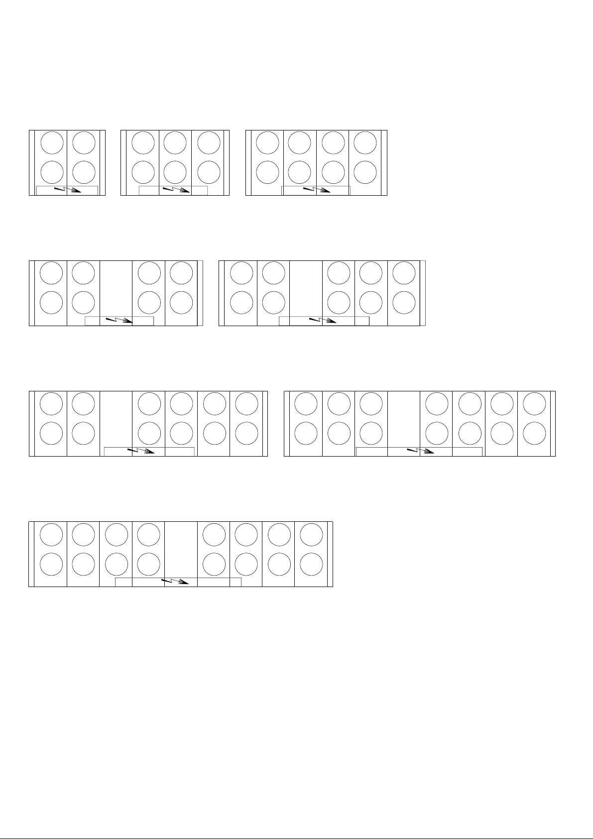
14.11 - 30GX fan arrangement
EV31
EV12 EV11
EV31
EV32
EV31
EV32
GX082/102
EV33
EV34
EV33
EV31
EV13 EV12
EV13
EV14
GX182
EV17
EV32 EV33
GX112/132
EV11
EV12
EV15
EV11
EV13
EV31
EV32
EV11
EV31
EV14 EV13
EV32 EV33
GX152/162
EV33
EV34
GX207/227
EV31
EV34
EV12 EV11
EV15
EV16
EV33
EV13
EV14
EV35
EV11
EV12
EV17
EV15
EV13
EV11
EV32
EV31
EV32
EV34
EV33
EV34
EV18
GX247/267
EV35
EV36
EV37
EV38
EV16
EV14
EV17
EV18
GX328/358
EV12
EV15
EV16
EV13
EV14
EV32
EV11
EV12
EV34
EV36
GX298
EV18
EV16
EV14
EV12
28
Page 29

15 - MAINTENANCE
15.1 - Refrigerant charging - adding charge
IMPORT ANT
These units are designed for use with R-134a only. DO NOT
USE ANY OTHER refrigerant in these units.
CAUTION
When adding or removing charge, circulate water through
the condenser (HX) and cooler at all times to prevent
freezing. Freezing damage is considered abuse and may void
the Carrier warranty.
CAUTION
DO NOT OVERCHARGE system. Overcharging results in
higher discharge pressure with higher cooling fluid
consumption, possible compressor damage and higher power
consumption.
15.2 - Indication of low charge on a 30HXC system
NOTE
To check for low refrigerant charge on a 30HXC, several
factors must be considered. A flashing liquid-line sightglass is
not necessarily an indication of inadequate charge. There are
many system conditions where a flashing sightglass occurs
under normal operation. The 30HXC metering device is
designed to work properly under these conditions.
1. Make sure that the circuit is running at a full-load condition. To check whether circuit A is fully loaded, follow the
procedure described in the Controls manual.
2. It may be necessary to use the Manual Control feature to
force the circuit into a full-load condition. If this is the case,
see the instructions for using the Manual Control feature in
the Controls manual.
3. With the circuit running at full-load, verify that the cooler
leaving fluid temperature is in the range of 6°C ± 1.5.
4. At this condition, observe the refrigerant in the liquid line
sightglass. If there is a clear sightglass, and no signs of
flashing, then the circuit is adequately charged. Skip the
remaining steps.
5. If the refrigerant appears to be flashing, the circuit is
probably low on charge. Verify this by checking the EXV
position (see Controls IOM).
6. If the opening position of the EXD is greater than 60%, and
if the liquid-line sightglass is flashing, then the circuit is
low on charge. Follow the procedure for adding charge.
15.2.1 - To add charge to the 30HXC systems
1. Make sure that the unit is running at full-load, and that the
cooler leaving fluid temperature is in the range of 5.6 -
7.8 °C.
2. At these operating conditions, check the liquid-line
sightglass. If there is a clear sightglass, then the unit has
sufficient charge. If the sightglass is flashing, then check
the EXD Percent Open. If this is greater than 60%, then
begin adding charge.
3. Add 2.5 kg of liquid charge into the evaporator using the
charging valve located on the top of the evaporator.
4. Observe the EXD Percent Open value. The EXD should
begin closing as charge is being added. Allow the unit to
stabilize. If the EXD Percent Open remains above 60%, and
there are still bubbles in the sightglass, add an additional
2.5 kg of liquid charge.
5. Allow the unit to stabilize, and again check the EXD
Percent Open. Continue adding 2.5 kg of liquid refrigerant
charge at a time, and allow the unit to stabilize before
checking the EXD position.
6. When the EXD Percent Open is in the range of 40 - 60%,
check the liquid line sightglass. Slowly add enough
additional liquid charge to ensure a clear sightglass. This
should be done slowly to avoid overcharging the unit.
7. Verify adequate charge by continuing to run at full-load
with 6°C ± 1.5 evaporator leaving fluid temperature. Check
that the refrigerant is not flashing in the liquid-line
sightglass. The EXD Percent Open should be between 40
and 60%. The cooler level indicator should be in the range
of 1.5 - 2.5.
15.2.2 - Indication of low charge on 30GX systems
1. Make sure that the circuit is running at a full-load condition
and that the condensing temperature is 50°C ± 1.5. To
check whether circuit A is fully-loaded, follow the
procedure in the Controls IOM.
2. It may be necessary to use the Manual Control feature to
force the circuit into a full-load condition. If this is the case,
see the instructions for using the Manual Control function
(procedure in the Controls IOM).
3. With the circuit running at full-load, verify that the cooler
leaving fluid temperature is in the range of 6°C ± 1.5.
4. Measure the air temperature entering the condenser coils.
Measure the liquid temperature after the tee where the two
coil liquid lines join. The liquid temperature should be
8.3°C above the air temperature entering the coils. If the
difference is more than this and the sightglass is flashing,
the circuit is uncharged. Proceed to step 5.
5. Add 2.5 kg of liquid charge into the cooler using charging
valve located in the top of the cooler.
6. Allow the system to stabilize and then recheck the liquid
temperature. Repeat step 5 as needed allowing the system
to stabilize between each charge addition. Slowly add
charge as the sightglass begins to clear to avoid overcharging.
15.2.3 - Space temperature, outdoor air temperature
(optional)
These temperatures are used to measure the temperature of the
space or the outside air temperature respectively for reset
control based on Outside Air or Space Temperature reset
options.
NOTE
A flashing liquid-line sightglass at operating conditions other
than those mentioned above is not necessarily an indication
of low refrigerant charge.
29
Page 30

15.3 - Pressure transducers
15.3.1 - Discharge pressure (circuits A & B)
This input is used to measure the high side pressure of each
circuit of the unit.
It is used to provide the pressure to replace the discharge
pressure gauge and to control the head pressure.
15.3.2 - Suction pressure (circuits A & B)
This input is used to measure the pressure of the low side of
the unit. It is used to provide the pressure to replace the suction
pressure gauge.
15.3. 3 - Oil pressure (each compressor)
This input is used to measure the oil pressure of each
compressor of the unit. It is located on the oil pressure port of
each compressor.
15.3.4 - Economizer pressure (circuits A & B)
This input is used to monitor the oil pressure differential
supplied to the compressor.
15.4 - Oil charging - low oil recharging
15.4.1 - Addition of oil charge to 30HX/GX systems
1. If the 30HXC/GX unit shuts-off repeatedly on Low oil
Level, this may be an indication of inadequate oil charge. It
could also mean simply that oil is in the process of being
reclaimed from the low-side of the system.
2. Begin by running the unit at full-load for an hour and a
half.
3. After running for 1-1/2 hours allow the unit to re-start and
run normally. If the Low Oil Level alarms persist, the unit
has a low oil charge. Add oil to the oil separator, using the
oil charging valve at the bottom of the condenser (30HXC)
or at the bottom of the oil separator (30GX).
CAUTION
Do NOT add oil at any other location as improper unit
operation may result.
4. Make sure that the unit is not running when adding oil, as
this will make the oil charging process easier. Because the
system is under pressure even when the unit is not running,
it will be necessary to use a suitable pump (hand or electric
pump) to add oil to the system.
5. Using a suitable pump, add 2 litres of Polyolester oil to the
system (CARRIER SPEC: PP47-32). Make sure that the oil
level safety switch is NOT jumpered, and allow the unit to
re-start and run normally.
6. If low oil level problems persist, add another 1 or 2 litres of
oil. If it is necessary to add more than 4 litres of oil to the
system, then contact your Carrier distributor service
department.
CAUTION: When transferring the refrigerant charge to a
storage unit, oil may be carried along when the unit is not
operating. Reuse first of all the amount of refrigerant
transferred. After draining the oil, only recharge the amount
drained (an excess oil charge may impair correct unit
operation).
15.5 - Integral oil filter change
An integral oil filter in the 06N screw compressor is specified
to provide a high level of filtration (3 µ) required for long
bearing life. As system cleanliness is critical to reliable system
operation, there is also a prefilter (7 µ) in the oil line at the oil
seperator outlet.
The replacement integral oil filter element part number is:
Carrier part number (including filter and O-ring):
06NA 660016S
15.6 - Filter change-out schedule
The filter should be checked after the first 500 hours of
operation, and every subsequent 2000 hours. The filter should
be replaced at any time when the pressure differential across
the filter exceeds 2.1 bar.
The pressure drop across the filter can be determined by
measuring the pressure at the filter service port and the oil
pressure port. The difference in these two pressures will be the
pressure drop across the filter, check valve, and solenoid valve .
The pressure drop across the check valve and solenoid valve is
approximately 0.4 bar, which should be subtracted from the
two oil pressure measurements to give the oil filter pressure
drop. The oil filter pressure drop should be checked after any
occasion that the compressor is shut down on a low oil pressure safety.
15.7 - Filter change-out procedure
The following steps outline the proper method of changing the
integral oil filter.
1. Shutdown and lockout the compressor.
2. Manually force the operation of the oil solenoid valve, in
order to press the internal valve shutter onto its seat.
3. Close the oil filter service valve. Bleed pressure from the
filter cavity through the filter service port.
4. Remove the oil filter plug. Remove the old oil filter.
5. Prior to installing the new oil filter, “grease” the o-ring with
oil. Install the filter and replace the plug.
Before closing up the lube oil system, take the opportunity
to replace the prefilter, as well.
6. When complete, evacuate the filter cavity through the filter
service port. Open the filter service valve. Remove any
compressor lockout devices, the compressor is ready to
return to operation.
15.8 - Compressor replacement
15.8.1 - Compressor rotation control
Correct compressor rotation is one of the most critical application considerations. Reverse rotation, even for a very short
duration, damages the compressor.
The reverse rotation protection scheme must be capable of
determining the direction of rotation and stopping the
compressor within 300 milliseconds. Reverse rotation is most
likely to occur whenever the wiring to the compressor
terminals is disturbed.
30
Page 31

To minimize the oppor tunity for reverse rotation, the following
procedure must be applied. Rewire the power cables to the
compressor terminal pin as originally wired.
For replacement of the compressor, a low pressure switch is
included with the compressor. This low pressure switch should
be temporarily installed as a hard safety on the high pressure
part of the compressor. The purpose of this switch is to protect
the compressor against any wiring errors at the compressor
terminal pin. The electrical contact of the switch would be
wired in series with the high pressure switch. The switch will
remain in place until the compressor has been started and
direction of rotation has been verified; at this point, the switch
will be removed.
The switch that has been selected for detecting reverse rotation
is Carrier part number HK01CB001. It is available as part of
the "Compressor installation package" (part No. 06NA 660
013). This switch opens the contacts when the pressure falls
below 50 mm of vacuum. The switch is a manual reset type
that can be reset after the pressure has once again risen above
70 kPa. It is critical that the switch be a manual reset type to
preclude the compressor from short cycling in the reverse
direction.
15.8.2 - EXD Troubleshooting Procedure
Follow steps below to diagnose and correct EXD/
Economizer problems.
On 30HXC/GX units with economizers, verify that the valve
for the bubbler tube (bottom of Economizer) is open. Check
EXD motor operation first (see procedure in the Controls
IOM). You should be able to feel the actuator moving by
placing your hand on the EXD or economizer body (the
actuator is located about one-half to two-thirds of the way up
from the bottom of the economizer shell). You should feel a
hard knocking come from the actuator when it reaches the top
of its stroke (can be heard if surroundings are relatively quiet).
The actuator should knock when it reaches the bottom of its
stroke. If it is believed that the valve is not working properly,
contact your Carrier service department for further checks on:
• output signals on EXD module
• wire connections (continuity and tight connection at all pin
terminals)
• resistance of the EXD motor windings.
31
Page 32
16 - START-UP CKECKLIST FOR 30HXC/GX LIQUID CHILLERS (USE FOR JOB FILE)
Preliminary information
Job name:................................................................................................................................................................................................
Location:.................................................................................................................................................................................................
Installing contractor:...............................................................................................................................................................................
Distributor: .............................................................................................................................................................................................
Start-up preformed by: ...........................................................................................................................................................................
Compressors
Model:............................................................................................. S/N ..............................................................................................
Compresseurs
Circuit A Circuit B
1. Model # ...................................................................................... 1. Model # .................................................................................
S/N ............................................................................................. S/N ..............................................................................................
Mtr #........................................................................................... Mtr # ...........................................................................................
2. Model # ...................................................................................... 2. Model # .................................................................................
S/N ............................................................................................. S/N ..............................................................................................
Mtr #........................................................................................... Mtr # ...........................................................................................
Cooler
Model #........................................................................................... Manufactured by .........................................................................
S/N .................................................................................................. Date.............................................................................................
Condenser (30HXC)
Model #........................................................................................... Manufactured by .........................................................................
S/N .................................................................................................. Date.............................................................................................
Air handling equipment
Manufacturer ..........................................................................................................................................................................................
Model #........................................................................................... S/N ..............................................................................................
Additional air handling units and accessories ........................................................................................................................................
................................................................................................................................................................................................................
Preliminary equipment check
Is there any shipping damage ? ...................................................... If so, where ?...............................................................................
................................................................................................................................................................................................................
Will this damage prevent unit start-up ?.................................................................................................................................................
Unit is level in its installation
Power supply agrees with the unit nameplate
Electrical circuit wiring has been sized and installed properly
Unit ground wire has been connected
Electrical circuit protection has been sized and installed properly
All terminals are tight
All cables and thermistors have been inspected for crossed wires
All plug assemblies are tight
Check air handling systems
All air handlers are operating
All chilled water valves are open
All fluid piping is connected properly
All air has been vented from the system
Chilled water pump (CWP) is operating with the correct rotation. CWP amperage: Rated: ........... Actual............
32
Page 33

Check condenser system (30HXC)
All condenser water valves are open
All condenser piping is connected properly
All air has been vented from the system
Condenser water pump (CWP) is operating with the correct rotation.
Condenser water pump amperage: Rated:…….. Actual………
Unit start-up
CWP starter has been properly interlocked with the chiller
Oil heaters have been energized for at least 24 hours (30GX)
Oil level is correct
All discharge and liquid valves are open
All suction valves are open, if equipped
All oil line valves and economizer discharge bubbler valves (30HXC only if equipped) are open
Unit has been leak checked (including fittings)
Locate, repair, and report any refrigerant leaks
................................................................................................................................................................................................................
................................................................................................................................................................................................................
................................................................................................................................................................................................................
Check voltage imbalance: AB .................. AC................. BC ................
A v erage voltage =..................................... (see installation instructions)
Maximum deviation = .............................. (see installation instructions)
Voltage imbalance = ................................. (see installation instructions) .
Voltage imbalance is less than 2%
WARNING
Do not start chiller if voltage imbalance is greater than 2%. Contact local power company for assistance.
All incoming power voltage is within rated voltage range
Check cooler water loop
Water loop volume = ................................ (liters)
Calculated volume =................................. (liters)
3.25 liters/nominal kW capacity for air conditioning
6.5 liters/nominal kW capacity for process cooling
Proper loop volume established
Proper loop corrosion inhibitor included .............. liters of...........................
Proper loop freeze protection included (if required) ........................liters of .............................
Piping includes electric heater tape, if exposed to the outside
Inlet piping to cooler includes a 20 mesh strainer
Check pressure drop across the cooler
Entering cooler = ...................................... (kPa)
Leaving cooler =....................................... (kPa)
(Leaving - entering) = .............................. (kPa)
WARNING
Plot cooler pressure drop on performance data chart (in product data literature) to determine total liters per second (l/s) and find
unit's minimum flow rate.
Total l/s = ..................................................
l/s / nominal kW = ....................................
Total l/s is greater than unit's minimum flow rate
Total l/s meets job specified requirement of .......................................... (l/s)
Check condenser water loop
Proper loop corrosion inhibitor included .............. liters of...........................
Inlet piping to condenser includes a 20 mesh strainer
33
Page 34
Check pressure drop across the condenser (30HXC only)
Entering condenser =................................ (kPa)
Leaving condenser = ................................ (kPa)
(Leaving - entering) = .............................. (kPa)
WARNING
Plot condenser pressure drop on performance data chart (in product data literature) to determine total liters per second (l/s) and
find unit's minimum flow rate.
Total l/s = ..................................................
l/s / nominal kW = ....................................
Total l/s is greater than unit's minimum flow rate
Total l/s meets job specified requirement of .......................................... (l/s)
Perform TEST function (indicate positive result):
WARNING
Once power is supplied to the unit, check the display for any alarms, such as phase reversal. Follow the TEST function instructions in the Controls and Troubleshooting literature (follow the procedure in the Controls IOM).
Be sure all service valves are open before beginning the compressor test section.
External reset sensor ...................................................................
Cooler pump interlock ................................................................
Cooler fluid select .......................................................................... Cooler pump control ...................................................................
Minimum load select ...................................................................... Condenser pump control*...........................................................
Loading sequence select ................................................................. Condenser flow switch* ................. ............................................
Lead/lag sequence select ................................................................ Condenser water sensors* ..........................................................
Head pressure control .....................................................................
Motormaster select* ....................................................................... *If installed
Water valve type* ...........................................................................
To start the chiller
WARNING
Be sure that all service valves are open, and all pumps are on before attempting to start this machine. Once all checks have been
made, move the switch to "LOCAL" or "REMOTE" from "OFF".
Unit starts and operates properly
Temperatures and pressures
W ARNING
Once the machine has been operating for a while and the temperatures and pressures have stabilized, record the following
Cooler EWT ................................................................................... Ambient temperature (GX) .........................................................
Cooler LWT .................................................................................... Condenser EWT .........................................................................
Condenser LWT..........................................................................
Circuit A oil pressure ...................................................................... Circuit B oil pressure ..................................................................
Circuit A suction pressure............................................................... Circuit B suction pressure...........................................................
Circuit A discharge temperature ..................................................... Circuit B suction temperature.....................................................
Circuit A suction temperature......................................................... Circuit B discharge pressure.......................................................
Circuit A discharge pressure........................................................... Circuit B discharge temperature .................................................
Circuit A liquid line temperature.................................................... Circuit B liquid line temperature ................................................
NOTES:
...............................................................................................................................................................................................................
...............................................................................................................................................................................................................
...............................................................................................................................................................................................................
...............................................................................................................................................................................................................
...............................................................................................................................................................................................................
34
Page 35

Page 36

Order No: 13173-76, 03 1999 - Supersedes No: 13173-76, March 1998 Manufacturer: Carrier s.a., Montluel, France.
Manufacturer reserves the right to change any product specifications without notice. Printed in the Netherlands on chlorine-free paper.
 Loading...