

Page 1
25VNA4
INFINITY®
VARIABLE SPEED HEAT PUMP
WITH GREENSPEED™ INTELLIGENCE
2 TO 5 NOMINAL TONS
PRODUCT DATA
Carrier’s 25VNA4 with Greenspeed™ Intelligence is a breakthrough
product providing up to 13 HSPF heating efficiency and up to 24 SEER
cooling efficiency. The variable speed capacity control results in strong
heating capacity as the outdoor temperature drops resulting in less
reliance on auxiliary heat. Lower speed operation, when needed in
cooling, for enhanced comfort and dehumidification.
This product has been designed and manufactured to meet Energy Star®
criteria for energy efficiency when matched with appropriate coil
components. Refer to the combination ratings in this Product Data for
system combinations that meet Energy Star guidlines.
NOTE: Ratings contained in this document are subject to change at any
time. Always refer to the AHRI directory (www.ahridirectory.org) for
the most up-to-date ratings information.
Industry leading Features / Benefits
Energy Efficiency
• Up to 24 SEER, 15 EER, 13 HSPF
• Microtube Technology™ refrigeration system
• Indoor air quality accessories available
Sound
• Sound level as low as 51 dBA in low speed .
Comfort
• Variable speed compressor with capacity range from 25-100%
• Air cooled Inverter variable speed drive
– System requires Infinity Control with Greenspeed capability
– Energy Tracking capability with the Infinity Control Wall Control
w/latest software version
(Energy Tracking has the ability to monitor and estimate the energy
consumption of your Infinity system.)
Reliability
• Non-ozone depleting Puron® refrigerant
• Front-seating service valves
• Greenspeed Intelligence actively monitors critical system parameters
• High pressure switch
• Discharge pressure transducer
• Electronic expansion valve (EXV) for heating, TXV for cooling
• Filter drier (field installed)
• Internal crankcase heater standard
Flexibility and installation:
• 2 control wires to outdoor unit
• Minimum and maximum airflow adjustments
• Compressor heating capacity control
• Hybrid Heat™ Dual Fuel capable
Durability
WeatherArmor Ultra™ protection package:
• Solid, Durable sheet metal construction
• Steel louver coil guard
• Baked-on, complete outer coverage, powder paint
Applications
• Long-line - up to 250 feet (76.2 m) total equivalent length, up to 200
feet (60.96 m) condenser above evaporator, or up to 80 ft. (24.38 m)
evaporator above condenser (See Longline Guide for more
information.)
Page 2

25VNA4: PRODUCT DATA
Use of the AHRI Certified
TM Mark indicates a
manufacturer’s
participation in the
program For verification
of certification for individual
products, go to
www.ahridirectory.org.
®
Quality
ISO 9001
This product has been designed and manufactured to
meet Energy Star criteria for energy eciency when
matched with appropriate coil components. However,
proper refrigerant charge and proper air ow are critical
to achieve rated capacity and eciency. Installation of
this product should follow all manufacturing refrigerant
charging and air ow instructions. Failure to conrm
proper charge and air ow may reduce energy
eciency and shorten equipment life.
Model Number Nomenclature
1 2 3 4 5 6 7 8 9 10 11 12 13
N N A A A/N N N N A/N A/N A/N N N
2 5 V N A 4 3 6 A 0 0 3 0
Product
Series
25 = HP V = VS HP
Product
Family
Tier
N=
Infinity Series
Major
Series
A = Puron
SEER
Cooling
Capacity
1,000 Btuh
(nominal)
Variations Open Open Voltage
A = Standard
0=Not
Defined
0=Not
Defined
3=208/230-1 0, 1, 2...
Standard Features
FEATURES
24 36 48 60
Puron Refrigerant X X X X
Variable Speed Rotary Compressor X X X
Variable Speed Scroll Compressor X
Air-Cooling Inverter Drive X X X X
Louvered Coil Guard X X X X
Field-Installed Filter Drier X X X X
Front-Seating Service Valves X X X X
Internal Pressure and Temperature Protection X X X X
Suction Pressure Transducer X X X X
High Pressure Switch X X X X
Crankcase Heater X X X X
Utility Interface Connections X X X X
Bluetooth® Module X X X X
Enhanced Diagnostics X X X X
Energy Tracking Capability X X X X
Dual Sound Blanket X X X X
Outdoor Air Temperature Sensor X X X X
Long Line Capability X X X X
X = Standard
Unit Size
Minor
Series
Manufacturer reserves the right to change, at any time, specifications and designs without notice and without obligations.
2
Page 3

25VNA4: PRODUCT DATA
Refrigerant Piping Length Limitations
Maximum Line Lengths:
The maximum allowable total equivalent length for heat pumps varies depending on the vertical separation. See the tables below for allowable lengths
depending on whether the outdoor unit is on the same level, above or below the outdoor unit.
Maximum Line Lengths for Heat Pump Applications
MAXIMUM ACTUAL LENGTH
Units on equal level 200 (61) 250 (76.2) N/A
Outdoor unit ABOVE
indoor unit
Outdoor unit BELOW
indoor unit
*.Maximum actual length not to exceed 200 ft (61 m)
†.Total equivalent length accounts for losses due to elbows or fitting. See the Long Line Guideline for details.
ft (m)
200 (61) 250 (76.2) 200 (61)
Maximum Total Equivalent Length* - Outdoor Unit BELOW Indoor Unit
Liquid Line
Size
Diameter
w/ TXV
0-20
(0 - 6.1)
21-30
(6.4 - 9.1)
024 3/8 250* 250* 250* 250* 250* 250* 250*
036 3//8 250* 250* 250* 250* 250* 250* 250*
048 3/8 250* 250* 250* 250* 230 160 --
060 3/8 250* 225* 190 150 110 -- --
*.Total equivalent length accounts for losses due to elbows or fitting. See the Long Line Guideline for details.
-- = Outside acceptable range.
*
See Table ’Maximum Total Equivalent Length: Outdoor Unit BELOW Indoor Unit’
MAXIMUM EQUIVALENT LENGTH
ft (m)
†
MAXIMUM VERTICAL SEPARATION ft
HP with Puron® Refrigerant - Maximum Total Equivalent Length
Vertical Separation ft (m) Outdoor unit BELOW indoor unit;
31-40
(9.4 - 12.2)
41-50
(12.5 - 15.2)
51-60
(15.5 - 18.3)
(18.6 - 21.3)
*
61-70
(m)
71-80
(21.6 - 24.4)
Long Line Applications
An application is considered Long Line when the refrigerant level in the system requires the use of accessories to maintain acceptable refrigerant
management for systems reliability. Defining a system as long line depends on the liquid line diameter, actual length of the tubing, and vertical
separation between the indoor and outdoor units.
For Heat Pump systems, the chart below shows when an application is considered Long Line. Beyond these lengths, long line accessories are
required:
HP with Puron® Refrigerant Long Line Description ft (m)
Beyond these lengths, long line accessories are required
Liquid Line Size Units On Same Level Outdoor Below Indoor Outdoor Above Indoor
3/8 80 (24.4) 20 (6.1) vertical or 80 (24.4) total 80 (24.4)
NOTE: See Long Line Guideline for details
COOLING CAPACITY LOSS TABLE
Nominal
Size
(Btuh)
24000
36000
48000
60000
Rating size in BOLD
Line OD (in)
= TE Length greater than 80 ft requires long line accessory liquid line solenoid.
25 50 75 80
5/8 0.5 1.0 2.0 2.0
3/4 0.0 0.5 0.5 0.5
5/8 1.0 2.5 3.5 4.0
3/4 0.5 1.0 1.5 1.5
7/8 0.0 0.5 0.5 0.5
3/4 0.5 1.5 2.5 2.5
7/8 0.5 0.5 1.0 1.0
1 1/8 0.0 0.0 0.0 0.5
3/4 1.0 2.5 3.5 4.0
7/8 0.5 1.0 1.5 2.0
1 1/8 0.0 0.0 0.5 0.5
Cooling Capacity Loss (%)
Total Equivalent Length (ft)
100 125 150 175 200 225 250
2.5 3.0 3.5 4.5 5.0 5.5 6 .0
1.0 1.0 1.5 1.5 2.0 2.0 2 .5
5.0 6.5 7.5 9.0 10.5 11.5 13.0
2.0 2.5 3.0 3.0 3.5 4.0 4.5
1.0 1.0 1.5 1.5 2.0 2.0 2.5
3.0 4.0 5.0 5.5 6.5 7.5 8.0
1.5 2.0 2.5 3.0 3.0 3.5 4.0
0.5 0.5 0.5 0.5 1.0 1.0 1.0
5.0 6.0 7.5 8.5 10.0 11.0 12.5
2.5 3.0 3.5 4.0 5.0 5.5 6.0
0.5 0.5 1.0 1.0 1.0 1.5 1.5
Manufacturer reserves the right to change, at any time, specifications and designs without notice and without obligations.
3
Page 4

25VNA4: PRODUCT DATA
Equipment sizing Guidelines
If primary load is cooling, size the same as any other air conditioning system. If primary load is heating, use the chart below for maximum size for
heating.
Maximum Recommended Equipment Size - Heating
COOLING LOAD (tons) MAXIMUM RECOMMENDED EQUIPMENT SIZE FOR HEATING
2 36
2.5 36
3 48
3.5 60
4 60
5 60
*. Make sure duct work is capable of delivering required airflow . Make sure combination rating exists for desired combination
*
MIN/MAX Airflow tables
The indoor airflow delivered by this system varies significantly based on outdoor temperature, indoor unit combination, and system demand. The
airflows on these tables are for duct design considerations.
Duct systems capable of these ranges will ensure the system will deliver full capacity at all outdoor temperatures.
Minimum and maximum airflows can be adjusted from these numbers in the Infinity Control Heat Pump Setup screen.
Size
24 700 300 900 500
36 750 300 1100 300
48 1200 500 1600 600
60 1400 500 2000 750
Size
24 850 300 1000 650
36 1500 300 1500 650
48 1550 500 1600 600
60 2000 500 2000 850
Max Capacity Min Capacity Max Capacity Min Capacity
Max Capacity Min Capacity Max Capacity Min Capacity
Cooling - Comfort Mode Cooling - Efficiency Mode
Heating - Comfort Mode Heating - Efficiency Mode
Manufacturer reserves the right to change, at any time, specifications and designs without notice and without obligations.
4
Page 5

25VNA4: PRODUCT DATA
Physical Data
UNIT SIZE SERIES 24-30 36-30 48-30 60-30
COMPRESSOR TYPE Variable Speed rotary Variable Speed Scroll
REFRIGERANT Puron® (R-410A)
Control TXV (Puron® Hard Shutoff)
Charge lb (kg) 8.9 (4.05) 14.1 (6.4) 14.15 (6.42) 16.25 (7.37)
Outdoor Htg Exp. Device EXV EXV EXV EXV
COND FAN Forward Swept Propeller Type, Direct Drive
Air Discharge Vertical
Air Qty (CFM) 3100 4100 4700 4700
Motor HP 1/3 1/3 1/3 1/3
Motor RPM 200-800 200-800 200-800 200-800
COND COIL
Face Area (Sq ft) 30.25 33 33 33
Fins per In. 20 20 20 20
Rows 2 2 2 2
Circuits 5 8 9 9
VALVE CONNECT. (In. ID)
Vapor 3/4 7/8 7/8 7/8
Liquid 3/8
REFRIGERANT TUBES (In. OD)
Rated Vapor
*
Max Liquid Line 3/8
*. Units are rated with 25 ft (7.6 m) of lineset length. See Vapor Line Sizing and Cooling Capacity Loss table when using other sizes and lengths of lineset.
Note: See unit Installation Instruction for proper installation.
3/4 7/8 1-1/8 1-1/8
Electrical Data
UNIT SIZE-VOLTAGE, SERIES V/PH
30
24-
36-
30 N/A 13.7 0.88 18.0 30
48-
30 N/A 21.2 0.88 27.4 40
60-
30 N/A 26.6 0.88 34.2 50
*. Permissible limits of the voltage range at which the unit will operate satisfactorily
†. Time-Delay fuse.
FLA - Full Load Amps
LRA - Locked Rotor Amps
MCA - Minimum Circuit Amps
RLA - Rated Load Amps
NOTE: Control circuit is 24-V on all units and requires external power source. Copper wire must be used from service disconnect to unit.
All motors/compressors contain internal overload protection.
Complies with 2010 requirements of ASHRAE Standards 90.1
208-230-1 253 197
OPER VOLTS
MAX MIN LRA RLA FLA
*
COMPR FAN
N/A 12.4 0.88 16.4 25
Charging Subcooling (TXV-Type Expansion Device)
UNIT SIZE-VOLTAGE, SERIES REQUIRED SUBCOOLING _F (_C) - See UI
24-30
36-30
48-30
60-30
Subcooling recommendation displayed on UI in Charging Mode must be
followed
MCA
†
MAX FUSE
CKT BRK AMPS
or
Manufacturer reserves the right to change, at any time, specifications and designs without notice and without obligations.
5
Page 6

25VNA4: PRODUCT DATA
Accessories
KIT NUMBER KIT NAME 24-30 36-30 48-30 60-30
KSASF0201AAA SUPPORT FEET X X X X
KHASS0606MPK SNOW STAND X X X X
KSATX0301PUR TXV KIT X X
KSBTX0301PUR TXV KIT X X
KSATX0401PUR TXV KIT X X
KSBTX0401PUR TXV KIT X X
x = Accessory
ACCESSORY USAGE GUIDELINE
REQUIRED FOR
ACCESSORY
Crankcase Heater Standard Standard Standard
Evaporator Freeze Protection Standard with Infinity Control No No
Liquid-Line Solenoid Valve No Yes No
Low-Ambient Control Standard with Infinity Control No No
Puron Refrigerant Balance Port
Hard-ShutOff TXV
Support Feet Recommended No Recommended
Winter Start Control Standard with Infinity Control No No
*. For tubing set lengths between 80 and 200 ft. (24.38 and 60.96 m) horizontal or 20 ft. (6.10 m) vertical differential (total equivalent length), refer to the Long Line Guideline—Air
Conditioners and Heat Pumps using Puron® Refrigerant.
†. Required on all indoor units. Standard on all new Greenspeed compatible fan coils and furnace coils.
LOW-AMBIENT COOLING
APPLICATIONS
(Below 55°F/12.8_C)
†
Yes
REQUIRED FOR LONG LINE
APPLICATIONS
(Over 80 ft/24.38 m)
Yes
*
†
REQUIRED FOR SEA
COAST APPLICATIONS
(Within 2 miles/3.22 km)
†
Yes
Accessory Description and Usage (Listed Alphabetically)
1. Compressor Start Assist
The inverter drive gently starts the variable speed compressor at all times. No other start device is compatible with this unit.
2. Crankcase Heater
This unit has a compressor crankcase heater that will be energized to prevent the compressor from being the coldest part of the system thus enhancing
reliability. the indoor unit and UI do not need to be installed for the crankcase heater to operate properly..
3. Liquid-Line Solenoid Valve (LLS)
An electrically operated shutoff valve which stops and starts refrigerant liquid flow in response to compressor operation. It is to be installed at the
outdoor unit to control refrigerant off cycle migration in the OFF mode.
Usage Guideline:
An LLS is required in all long line applications to control refrigerant off cycle migration in the OFF mode. See Long Line Guideline.
Suggested for all commercial applications.
4. Snow Stand
Coated wire rack which supports unit 18 in. (457.2 mm) above mounting pad to allow for drainage from unit base.
Usage Guideline:
Suggested in the following applications:
- Unit installations in heavy snowfall areas.
- Unit installations in snow drift locations.
- Unit installations in areas of prolonged subfreezing temperatures.
- All commercial installations.
5. Thermostatic Expansion Valve (TXV) Bi-Flow
A modulating flow-control valve which meters refrigerant liquid flow rate into the evaporator in response to the superheat of the refrigerant gas
leaving the evaporator.
Usage Guideline:
Accessory required to meet AHRI rating and system reliability, where indoor not equipped.
Manufacturer reserves the right to change, at any time, specifications and designs without notice and without obligations.
6
Page 7

25VNA4: PRODUCT DATA
Sound Power Level (dBA)
Unit Size Typical Octave Band Spectrum Min Speed Cooling Max Speed Cooling Min Speed Heating Max Speed Heating
Speed 900 3480 900 6000
125 53.5 61.3 53.2 69.5
250 53.0 55.2 54.7 70.3
500 47.4 53.2 49.4 68.1
24
36
48
60
NOTE: Tested in compliance with AHRI 270-2008 but not listed with AHRI.
1000 44.5 53.6 43.6 67.9
2000 37.1 49.8 39.1 65.6
4000 33.9 50.5 38.5 66.7
8000 42.3 49.6 41.8 63.3
Sound Rating (dBA) 51 59 52 74
Speed 900 3960 900 6060
125 57.4 62.6 54.9 70.8
250 62.2 62.5 58.8 72.8
500 49.9 60.5 45.9 65.6
1000 47.5 59.5 49.0 63.4
2000 43.5 54.7 44.3 65.0
4000 39.1 51.3 38.7 58.7
8000 46.7 48.6 44.3 55.6
Sound Rating (dBA) 56 64 54 71
Speed 900 3060 900 4700
125 55.0 67.4 55.6 75.4
250 59.7 66.5 60.4 64.9
500 51.9 64.4 52.5 64.1
1000 47.6 59.7 49.9 60.3
2000 44.2 57.2 42.6 68.8
4000 45.9 55.3 36.5 56.5
8000 43.2 55.4 43.6 54.6
Sound Rating (dBA) 56 66 56 72
Speed 960.0 3420.0 900.0 4500.0
125 59.6 71.1 55.0 65.8
250 60.6 71.7 55.4 70.1
500 57.4 70.5 51.7 65.4
1000 50.6 66.4 47.5 63.4
2000 48.3 65.2 45.7 63.7
4000 41.2 58.3 41.3 62.6
8000 42.6 55.7 41.5 55.4
Sound Rating (dBA) 58 72 54 71
Manufacturer reserves the right to change, at any time, specifications and designs without notice and without obligations.
7
Page 8

Dimensions
INC H
MM INCH MM INCH MM INCH MM INCH MM INCH MM INCH MM INCH MM INCH MM INCH MM INCH MM Lbs Kgs Lbs Kgs INCH MM INCH MM
25VNA424A0030050 0 Y N N N 35 889.0 43 13/16 1112.6 3/4 19.1 6 9/16 166.1 28 7/16 722.8 9 1/8 231.3 1 1/8 28.2 3 13/16 97.4 15 7/8 403.2 16 3/8 415.9 20 1/2 520.7 276 125.2 298 135.2 37 13/16 960.0 48 5/8 1235.0
25VNA436A0030050 0 Y N N N 35 889.0 47 3/16 1199.0 7/8 22.2 6 9/16 166.1 28 7/16 722.8 9 1/8 231.3 1 1/8 28.2 3 13/16 97.4 16 1/2 419.1 16 1/2 419.1 21 533.4 344 156.0 367 166.5 37 13/16 960.0 52 1321.4
25VNA448A0030050 0 Y N N N 35 889.0 47 3/16 1199.0 7/8 22.2 6 9/16 166.1 28 7/16 722.8 9 1/8 231.3 1 1/8 28.2 3 13/16 97.4 16 1/2 419.1 16 1/2 419.1 21 533.4 373 169.2 396 179.6 37 13/16 960.0 52 1321.4
25VNA460A0030040 0 Y N N N 35 889.0 47 3/16 1199.0 7/8 22.2 6 9/16 166.1 28 7/16 722.8 9 1/8 231.3 1 1/8 28.2 3 13/16 97.4 16 1/2 419.1 16 1/2 419.1 21 533.4 380 172.4 403 182.8 37 13/16 960.0 52 1321.4
OPER ATING
WEIGHT
SHIPPING
WEIGHT
SHIPPING
LENGT H /
WIDTH (Sq.)
U.S. ECCN: Not Subject to Regulation (N.S.R.)
208-230-1-60
208/230-3-60
460-3-60
575-3-60
Y=YE S
N=NO
NOTE: ALL DIMENSIONS IN INCH (MM)
C
25VNA4 SD5554-4 REV. B
SHIPPING
HEIGHT
DEF
UNIT
SERIES
ELECTRI CAL
CHARACTERISTI CS
ABGHIJK
NOTES:
1. CENTER OF GRA VITY .
UNIT SIZE
- 23 1/8 587.3 17 7/8 454.6
- 25 3/4 654.0 20 7/16 518.5
- 31 3/16 792.5 22 15/16 583.2
24,36,48,60 35 889.0 26 3/4 679.7
"Y"
MINIMUM ROO F-TO P MOUNTING
PAD A PPLICA TION DIMENSIONS
"X"
MINIMUM GROUND MOUNTING
PAD A PPLICATION DIMENSIO NS
Manufacturer reserves the right to change, at any time, specifications and designs without notice and without obligations.
25VNA4: PRODUCT DATA
8
Page 9
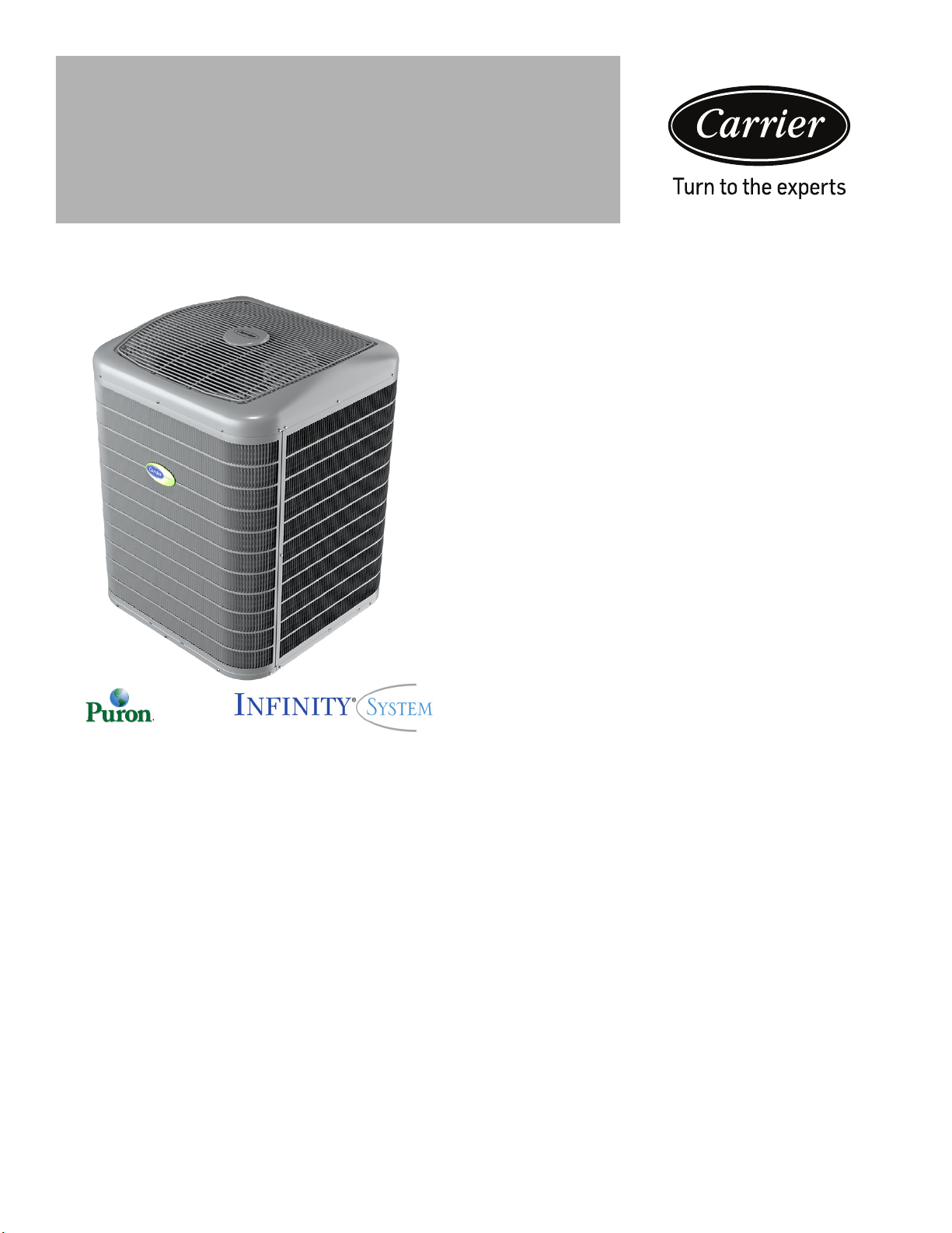
25VNA24 Balance Point Worksheet
0
2
4
6
8
10
0
5
10
15
20
25
30
35
40
-10 0 10 20 30 40 50 60 70 80
kW
BUILDING HEAT LOSS, UNIT INTEGRATED HEATI NG CAPACITY
(MBTU/HR)
OUTDOOR TEMPERATURE F
2 TON BALANCE POINT WORKSHEET
COMFORT MINIMUM AND MAXIMUM HEATING CAPACITIES
Minimum Capacity Maximum Capacity
Manufacturer reserves the right to change, at any time, specifications and designs without notice and without obligations.
25VNA4: PRODUCT DATA
9
Page 10
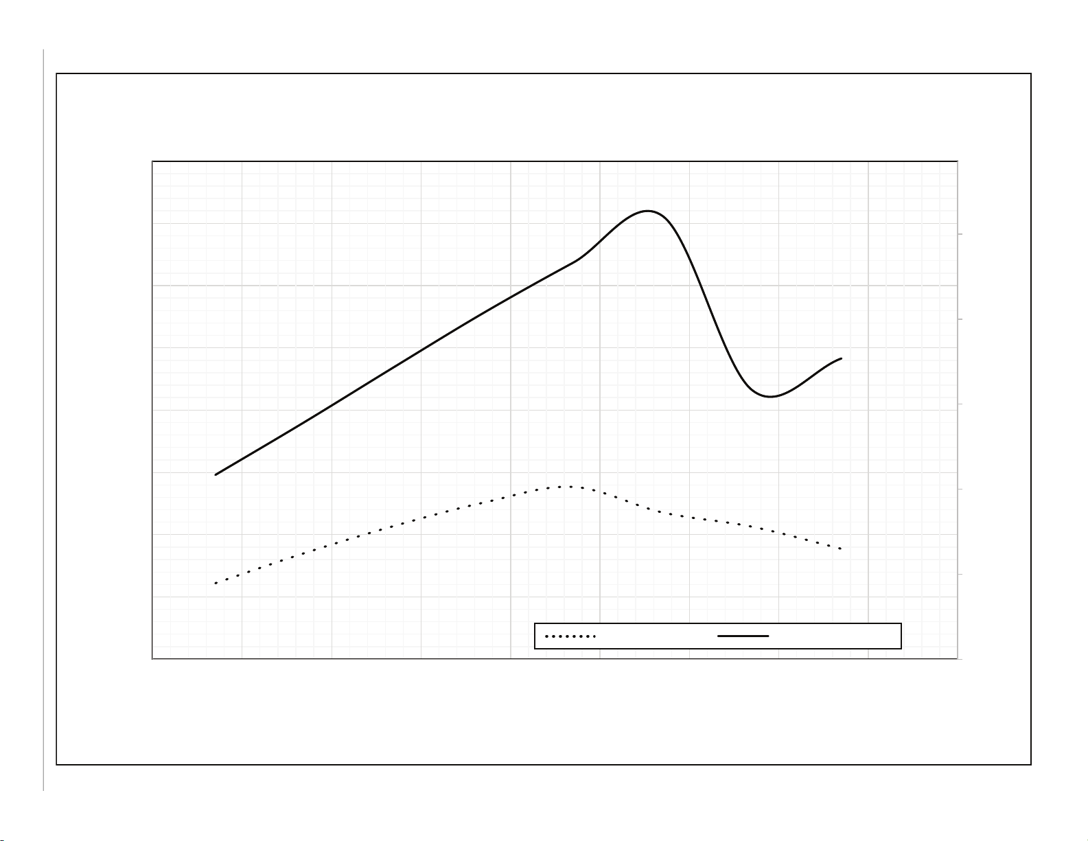
25VNA36 Balance Point Worksheet
0
2
4
6
8
10
12
14
0
5
10
15
20
25
30
35
40
45
50
-10 0 10 20 30 40 50 60 70 80
kW
BUIL DING HEAT LO SS, UNIT INTEG RATED HEAT ING CA PACITY
(MBTU/HR)
OUTDOOR TEMPERATURE F
3 TON BALANCE POINT WORKSHEET
COMFORT MINIMUM AND MAXIMUM HEATING CAPACITIES
Minimum Capacity Maximum Capacity
Manufacturer reserves the right to change, at any time, specifications and designs without notice and without obligations.
25VNA4: PRODUCT DATA
10
Page 11

25VNA48 Balance Point Worksheet
0
5
10
15
20
0
10
20
30
40
50
60
70
-10 0 10 20 30 40 50 60 70 80
kW
BUIL DING HEAT LO SS, UNIT INTEG RATED HEAT ING CA PACITY
(MBTU/HR)
OUTDOOR TEMPERATURE F
4 TON BALANCE POINT WORKSHEET
COMFORT MINIMUM AND MAXIMUM HEATING CAPACITIES
Minimum Capacity Maximum Capacity
Manufacturer reserves the right to change, at any time, specifications and designs without notice and without obligations.
25VNA4: PRODUCT DATA
11
Page 12

25VNA60 Balance Point Worksheet
0
5
10
15
20
0
10
20
30
40
50
60
70
-10 0 10 20 30 40 50 60 70 80
kW
BUIL DING HEAT LO SS, UNIT INTEG RATED HEAT ING CA PACITY
(MBTU/HR)
OUTDOOR TEMPERATURE F
5 TON BALANCE POINT WORKSHEET
COMFORT MINIMUM AND MAXIMUM HEATING CAPACITIES
Minimum Capacity Maximum Capacity
Manufacturer reserves the right to change, at any time, specifications and designs without notice and without obligations.
25VNA4: PRODUCT DATA
12
Page 13

Clearances
Clearances (various examples)
Wall
Wall
Wall
Wall
24”
Service
6”
(152.4 mm)
24”
(609.6)
Service
24”
(609.6)
Service
24”
(609.6)
Service
24”
(609.6)
Service
12”
(304.8)
12”
(304.8)
12”
(304.8)
12”
(304.8)
6”
(152.4)
Note: Numbers in ( ) = mm
24”
(609.6)
24”
(609.6)
24”
(609.6)
Manufacturer reserves the right to change, at any time, specifications and designs without notice and without obligations.
25VNA4: PRODUCT DATA
13
IMPORTANT: When installing multiple units in an alcove, roof well, or partially enclosed area, ensure there is adequate ventilation to prevent re-circulation of discharge air.
A07833
Page 14

Tested AHRI Combination Ratings*
NOTE: Ratings contained in this document are subject to change at any time.
For AHRI ratings certificates, please refer to the AHRI directory www.ahridirectory.org
Additional ratings and system combinations can be accessed via the Carrier database at: www.MyCarrierRatings.com Equipment performance
calculator can be accessed at: http://rpmob.wrightsoft.com/
Manufacturer reserves the right to change, at any time, specifications and designs without notice and without obligations.
25VNA4: PRODUCT DATA
Model Number Coil Model Number Clg Cap High EER SEER
25VNA424A**30 FE4ANF002L+UI 23400 14 22.0 850 500 24,000 3.78 11 24,400 2.62
25VNA436A**30 FE4AN(B,F)005L+UI 34600 13.5 22.5 1100 550 35,000 3.80 11 32,800 2.54
25VNA448A**30 FE4ANB006L+UI 46000 13.5 22.0 1600 600 46,000 3.92 11 42,500 2.60
25VNA460A**30 FE4ANB006L+UI 58500 13 21.0 1625 900 59,000 3.36 11 49,500 2.66
* Ratings are net values reflecting the effects of circulating fan heat. Supplemental electric heat is not included. Ratings are based on:
Cooling Standard: 80_F (27_C) db 67_F (19_C) wb indoor entering air temperature and 95_F (35_C) db air entering outdoor unit.
High-Temp Heating Standard: 70_F (21_C) db indoor entering air temperature and 47_F (8_C) db 43°F (6_C) wb air entering outdoor unit.
Low-Temp Heating Standard: 70_F (21_C) db indoor entering air temperature and 17_F (-8_C) db 15°F (-9_C) wb air entering outdoor unit.
COP — Coefficient of Performance
EER — Energy Efficiency Ratio
HSPF — Heating Seasonal Performance Factor
SEER — Seasonal Energy Efficiency Ratio
UI — User Interface
14
ID Heating 47°F Temp
High Low Capacity COP Capacity COP
HSPF
Heating 17°F Temp
Page 15

Detailed Cooling Capacities
25VNA42424/FE4ANB002 COOLING COMFORT + DEHUMIDIFY MODE CONDENSER ENTERING AIR TEMPERATURES °F (°C)
125 (46.1) 115 (46.1) 105 (40.6) 95 (35) 85 (29.4) 75 (23.9) 65 (18.3)
Capacity
ID
SCFM
MBtuh†
Total Sens‡ Total Sens‡ Tota l Sens ‡ Total Sens‡ Total Sens‡ Total Sens‡ Total Sens‡
20.65 8.49 2.39
18.67 11.49 2.37 20.17 12.10 2.10 21.50 12.70 1.85 22.74 13.27 1.63 23.95 13.78 1.44 24.91 14.44 1.34 25.00 14.37 1.34
630
17.18 13.84 2.35 18.54 14.43 2.08 19.78 15.07 1.84 20.94 15.68 1.63 22.05 16.19 1.45 23.04 17.07 1.35 23.24 16.98 1.33
15.96 15.96 2.33 16.96 16.96 2.06 17.93 17.93 1.82 19.06 18.35 1.62 19.66 19.58 1.46 20.97 20.05 1.35 21.53 19.23 1.32
20.56 11.51 2.39
18.60 14.48 2.37 20.10 15.09 2.10 21.43 15.74 1.85 22.67 16.35 1.63 23.88 16.86 1.44 24.84 17.75 1.34 24.93 17.59 1.34
630
17.36 16.50 2.36 18.56 17.38 2.08 19.79 18.08 1.84 20.94 18.74 1.63 22.04 19.25 1.45 23.04 20.36 1.35 23.22 20.18 1.33
17.03 17.03 2.35 18.09 18.09 2.07 19.10 19.10 1.83 20.04 20.04 1.63 20.87 20.87 1.46 21.97 21.97 1.35 22.06 22.06 1.33
17.83 7.24 2.00
16.11 9.48 1.98 17.47 10.05 1.78 18.55 10.54 1.64 17.21 10.00 1.15 17.73 10.22 0.98 18.12 10.52 0.86 18.11 10.46 0.87
465
14.82 11.22 1.96 16.06 11.78 1.77 17.07 12.29 1.63 15.84 11.78 1.16 16.34 12.00 0.99 16.80 12.44 0.87 16.88 12.39 0.87
13.37 13.37 1.94 14.52 13.80 1.75 15.58 14.06 1.62 14.18 14.18 1.16 14.80 14.06 1.00 15.25 14.66 0.88 15.35 14.76 0.87
17.75 9.52 2.00
16.06 11.71 1.98 17.43 12.29 1.78 18.50 12.79 1.64 17.16 12.28 1.15 17.68 12.50 0.98 18.06 12.91 0.86 18.05 12.81 0.87
465
14.81 13.44 1.96 16.05 14.01 1.77 17.05 14.54 1.63 15.83 14.04 1.16 16.33 14.27 0.99 16.79 14.83 0.87 16.87 14.72 0.87
14.25 14.25 1.95 15.18 15.18 1.76 15.97 15.97 1.62 15.09 15.09 1.16 15.47 15.47 0.99 16.00 16.00 0.88 16.05 16.05 0.87
14.29 5.75 1.68
12.90 7.20 1.65 13.90 7.64 1.49 14.63 7.97 1.35 11.39 6.54 0.76 10.86 6.33 0.61 11.09 6.42 0.48 11.06 6.41 0.51
300
11.85 8.31 1.63 12.75 8.74 1.47 13.45 9.08 1.33 10.43 7.65 0.77 9.97 7.44 0.62 10.19 7.54 0.50 10.23 7.56 0.52
10.43 9.93 1.60 11.20 10.34 1.45 11.83 10.68 1.31 9.21 9.21 0.78 8.91 8.91 0.63 9.05 9.05 0.51 9.16 9.16 0.52
14.26 7.22 1.68
12.87 8.65 1.65 13.87 9.10 1.49 14.61 9.42 1.35 11.35 8.00 0.76 10.83 7.78 0.61 11.06 7.87 0.48 11.03 7.86 0.51
300
11.83 9.76 1.63 12.73 10.19 1.47 13.43 10.53 1.33 10.41 9.10 0.77 9.96 8.89 0.62 10.18 8.99 0.50 10.22 9.01 0.52
10.87 10.87 1.61 11.49 11.49 1.45 11.98 11.98 1.31 9.83 9.83 0.77 9.51 9.51 0.62 9.66 9.66 0.50 9.73 9.73 0.52
Manufacturer reserves the right to change, at any time, specifications and designs without notice and without obligations.
15
See notes on page 22
EDB
°F (°C)
75
(23.9)
80
(26.7)
75
(23.9)
80
(26.7)
75
(23.9)
80
(26.7)
EVAP.AIR
EWB
°F (°C)
72 (22.2)
67 (19.4)
63 (17.2)
57 (13.9)
72 (22.2)
67 (19.4)
63 (17.2)
57 (13.9)
72 (22.2)
67 (19.4)
63 (17.2)
57 (13.9)
72 (22.2)
67 (19.4)
63 (17.2)
57 (13.9)
72 (22.2)
67 (19.4)
63 (17.2)
57 (13.9)
72 (22.2)
67 (19.4)
63 (17.2)
57 (13.9)
Total
Sys.
KW**
# -
Comfort + Dehumidify Mode
Capacity
ID
SCFM
22.32 9.10 2.11
630
22.23 12.12 2.11
630
19.37 7.83 1.79
465
19.31 10.09 1.79
465
15.46 6.23 1.50
300
15.42 7.69 1.50
300
MBtuh
Total
Sys.
KW**
SCFM
Capacity
ID
MBtuh
23.79 9.65 1.86
640
23.70 12.73 1.86
640
20.53 8.28 1.65
470
20.46 10.57 1.65
470
16.22 6.55 1.36
300
16.19 8.01 1.36
300
Total
ID
Sys.
SCFM
KW**
MAXIMUM DEMAND
650
650
MEDIAN DEMAND
475
475
MINIMUM DEMAND
300
300
Capacity
MBtuh
Total
Sys.
KW**
25.11 10.16 1.63
25.01 13.28 1.63
18.99 7.69 1.14
18.91 10.01 1.14
12.68 5.12 0.75
12.63 6.58 0.75
ID
SCFM
26.39 10.64 1.43
650
26.30 13.77 1.43
650
19.48 7.88 0.96
475
19.41 10.19 0.96
475
12.01 4.87 0.60
300
11.96 6.33 0.60
300
Capacity
MBtuh
Total
Sys.
KW**
Capacity MBtuh
ID
SCFM
27.22 11.00 1.32
700
27.12 14.34 1.32
700
19.77 8.01 0.84
500
19.69 10.43 0.84
500
12.14 4.92 0.46
300
12.09 6.38 0.46
300
Total
Sys.
KW**
ID
SCFM
27.13 10.95 1.34
680
27.03 14.20 1.34
680
19.62 7.94 0.86
490
19.51 10.31 0.86
490
12.03 4.87 0.49
300
11.85 6.28 0.49
300
Capacity
MBtuh
Total
Sys.
KW**
25VNA4: PRODUCT DATA
Page 16

Detailed Cooling Capacities
25VNA436/FE4ANB005 COOLING COMFORT + DEHUMIDIFY MODE CONDENSER ENTERING AIR TEMPERATURES °F (°C)
125 (46.1) 115 (46.1) 105 (40.6) 95 (35) 85 (29.4) 75 (23.9) 65 (18.3)
Capacity MBtuh†
ID
Total Sens}‡ Total Sens}‡ Tota l Sens}‡ Total Sens }‡ Total Sens}‡ Tot al Sens}‡ Total Sens}‡
26.89 10.51 3.15
650
26.80 13.67 3.15
650
20.98 8.20 2.33
480
20.92 10.58 2.33
480
16.87 6.59 2.05
400
16.82 8.50 2.05
400
Manufacturer reserves the right to change, at any time, specifications and designs without notice and without obligations.
16
See notes on page 22
EVAP. AIR
EDB
°F (°C)
(23.9)
(26.7)
(23.9)
(26.7)
(23.9)
(26.7)
EWB
°F (°C)
SCFM
72 (22.2)
67 (19.4) 23.99 13.53 3.15 25.40 14.14 2.80 26.59 14.79 2.44 28.86 16.11 2.23 28.87 16.11 1.86 25.34 13.38 1.45 24.95 13.19 1.38
75
63 (17.2) 21.87 15.88 3.14 23.14 16.47 2.79 24.27 17.25 2.44 26.37 18.83 2.24 26.40 18.84 1.87 23.18 14.96 1.45 22.90 14.79 1.37
57 (13.9) 19.21 19.21 3.11 20.23 19.91 2.78 22.05 19.63 2.44 23.18 22.82 2.24 23.23 22.85 1.88 20.30 17.28 1.46 20.09 17.16 1.35
72 (22.2)
67 (19.4) 23.92 16.66 3.15 25.31 17.25 2.79 26.52 18.06 2.44 28.79 19.71 2.23 28.80 19.71 1.86 25.30 15.56 1.45 24.92 15.38 1.38
80
63 (17.2) 21.85 19.00 3.14 23.11 19.59 2.79 24.24 20.51 2.44 26.35 22.42 2.24 26.38 22.43 1.87 23.14 17.13 1.45 22.85 16.98 1.37
57 (13.9) 20.56 20.56 3.13 21.48 21.48 2.78 22.53 22.53 2.44 24.59 24.59 2.24 24.64 24.64 1.87 19.45 19.45 1.46 20.13 19.34 1.35
72 (22.2)
67 (19.4) 18.64 10.44 2.33 19.01 10.61 1.96 19.35 10.80 1.64 20.50 11.42 1.44 20.02 11.21 1.15 18.59 9.87 0.99 1 8.01 9.59 0.95
75
63 (17.2) 16.92 12.19 2.33 17.27 12.35 1.96 17.60 12.59 1.65 18.67 13.33 1.45 18.26 13.13 1.16 16.99 11.14 1.00 16.50 10.89 0.94
57 (13.9) 14.71 14.71 2.31 15.03 14.94 1.96 15.33 15.24 1.66 17.01 15.11 1.46 16.01 15.95 1.17 14.83 12.99 1.00 14.47 12.78 0.93
72 (22.2)
67 (19.4) 18.59 12.81 2.33 18.96 12.97 1.96 19.29 13.22 1.64 20.45 13.96 1.44 19.97 13.76 1.15 18.56 11.60 0.99 17.97 11.32 0.95
80
63 (17.2) 16.89 14.55 2.33 17.25 14.72 1.96 17.57 15.00 1.65 18.65 15.86 1.45 18.25 15.67 1.16 16.96 12.86 1.00 16.47 12.61 0.94
57 (13.9) 15.81 15.81 2.32 16.06 16.06 1.96 16.37 16.37 1.65 17.36 17.36 1.46 17.09 17.09 1.17 14.71 14.71 1.00 14.51 14.50 0.93
72 (22.2)
67 (19.4) 14.96 8.37 2.05 15.18 8.47 1.71 14.90 8.34 1.37 15.24 8.50 1.15 14.55 8.20 0.92 14.01 7.52 0.91 13.85 7.44 0.84
75
63 (17.2) 13.55 9.77 2.05 13.74 9.88 1.71 13.51 9.75 1.38 13.84 9.91 1.16 13.22 9.62 0.93 12.78 8.57 0.91 12.67 8.52 0.83
57 (13.9) 11.76 11.76 2.04 11.90 11.90 1.71 11.77 11.77 1.39 12.04 11.98 1.17 11.61 11.61 0.94 11.15 10.11 0.90 11.08 10.08 0.81
72 (22.2)
67 (19.4) 14.90 10.27 2.05 15.12 10.36 1.71 14.85 10.25 1.37 15.20 10.40 1.15 14.51 10.11 0.92 13.98 8.94 0.91 1 3.82 8.87 0.84
80
63 (17.2) 13.52 11.66 2.05 13.72 11.75 1.71 13.49 11.65 1.38 13.83 11.80 1.16 13.23 11.52 0.93 12.76 9.99 0.91 1 2.64 9.95 0.83
57 (13.9) 12.62 12.62 2.04 12.78 12.78 1.71 12.62 12.62 1.39 12.87 12.87 1.17 12.44 12.44 0.93 11.35 11.35 0.90 11.29 11.29 0.81
Total
Sys.
KW**
# -
Comfort + Dehumidify Mode (cont.)
Capacity MBtuh
ID
SCFM
28.47 11.12 2.80
650
28.38 1 4.28 2 .80
650
21.41 8.36 1.95
480
21.34 1 0.75 1 .95
480
17.12 6.69 1.70
400
17.06 8.59 1.70
400
Total
Sys.
KW**
Capacity MBtuh
ID
SCFM
29.78 11.63 2.44
680
29.70 14.93 2.44
680
21.75 8.50 1 .63
490
21.68 10.93 1.63
490
16.80 6.56 1 .36
400
16.75 8.47 1 .36
400
Total
Sys.
KW**
Capacity MBtuh
ID
SCFM
MAXIMUM DEMAND
32.27 12.60 2.22
750
32.17 16.28 2.22
750
MEDIAN DEMAND
22.99 8.98 1.42
515
22.92 11.54 1.42
515
MINIMUM DEMAND
17.15 6.70 1.13
400
17.09 8.61 1.13
400
Total
Sys.
KW**
Capacity MBtuh
ID
SCFM
32.23 12.59 1.84
750
32.15 16.24 1.84
750
22.41 8.76 1.13
515
22.34 11.32 1.14
515
16.32 6.38 0.90
400
16.26 8.29 0.90
400
Total
Sys.
KW**
Capacity MBtuh
ID
SCFM
28.31 11.35 1.43
450
28.27 13.55 1.43
450
20.78 8.24 0.99
350
20.75 9.98 0.99
350
15.67 6.16 0.92
300
15.63 7.60 0.92
300
Total
Sys.
KW**
Capacity MBtuh
ID
SCFM
27.77 11.11 1.39
450
27.73 13.31 1.39
450
20.06 7.92 0.96
350
20.02 9.66 0.96
350
15.43 6.06 0.86
300
15.39 7.50 0.86
300
Total
Sys.
KW**
25VNA4: PRODUCT DATA
Page 17

Detailed Cooling Capacities
125 (46.1) 115 (46.1) 105 (40.6) 95 (35) 85 (29.4) 75 (23.9) 65 (18.3)
Capacity
ID
MBtuh†
Total Sens}‡ Total Sens}‡ Total S ens}‡ Total Sens}‡ Total Sens}‡ Total Sens}‡ Total Sens}‡
38.63 15.56 4.22
900
38.47 19.99 4.22
900
34.63 13.96 3.62
800
34.48 17.93 3.62
800
31.04 12.49 3.19
700
30.92 16.01 3.19
700
Manufacturer reserves the right to change, at any time, specifications and designs without notice and without obligations.
17
See notes on page 22
EDB
°F (°C)
75 (23.9)
80 (26.7)
75 (23.9)
80 (26.7)
75 (23.9)
80 (26.7)
EVAP.
AIR EWB
°F (°C)
SCFM
72 (22.2)
67 (19.4) 34.98 19.99 4.16 38.81 22.16 3.81 41.32 23.24 3 .45 44.55 25.12 3.13 47.48 26.86 2.82 49.18 27.60 2 .63 50.73 2 8.27 2.50
63 (17.2) 32.26 23.43 4.11 35.66 25.91 3.77 37.98 26.98 3 .42 40.99 29.25 3.12 43.81 31.41 2.83 45.53 32.21 2 .62 47.15 3 2.97 2.49
57 (13.9) 29.00 27.80 4.04 31.61 31.36 3.71 33.62 32.49 3 .38 36.34 35.29 3.10 38.93 37.99 2.82 40.57 38.89 2 .60 42.13 3 9.75 2.45
72 (22.2)
67 (19.4) 34.91 24.38 4.16 38.72 27.03 3.81 41.24 28.11 3 .45 44.46 30.46 3.13 47.37 32.67 2.82 49.07 33.41 2 .63 50.62 3 4.09 2.50
63 (17.2) 32.22 27.80 4.11 35.63 30.76 3.77 37.94 31.84 3 .42 40.95 34.57 3.12 43.77 37.21 2.83 45.48 38.01 2 .62 47.09 3 8.77 2.49
57 (13.9) 30.33 30.33 4.07 33.52 33.52 3.74 35.24 35.24 3 .40 38.17 38.17 3.11 40.96 40.96 2.82 42.32 42.32 2 .61 43.62 4 3.62 2.46
72 (22.2)
67 (19.4) 31.31 17.93 3.57 33.90 19.04 3.24 33.78 19.04 2 .62 33.33 18.87 2.07 32.59 18.80 1.57 33.84 19.38 1 .41 34.87 1 9.81 1.19
63 (17.2) 28.82 20.99 3.53 31.12 22.06 3.21 31.06 22.05 2 .61 30.64 21.94 2.07 30.11 22.20 1.59 31.48 22.86 1 .43 32.82 2 3.48 1.23
57 (13.9) 25.46 25.39 3.47 27.44 26.49 3.16 27.40 26.55 2 .58 27.08 26.45 2.07 26.86 26.86 1.60 28.07 27.76 1 .44 29.39 2 8.49 1.26
72 (22.2)
67 (19.4) 31.21 21.86 3.57 33.83 22.99 3.24 33.71 23.00 2 .62 33.25 22.87 2.07 32.48 23.12 1.57 33.76 23.66 1 .40 34.74 2 4.08 1.19
63 (17.2) 28.78 24.93 3.53 31.08 26.00 3.21 31.02 26.02 2 .61 30.62 25.92 2.07 30.09 26.48 1.59 31.45 27.12 1 .43 32.78 2 7.74 1.23
57 (13.9) 27.12 27.12 3.50 28.76 28.76 3.18 28.77 28.77 2 .59 28.53 28.53 2.07 28.60 28.60 1.60 29.69 29.69 1 .44 30.78 3 0.78 1.25
72 (22.2)
67 (19.4) 28.00 15.97 3.16 30.21 16.92 2.84 26.46 14.82 1 .96 21.81 12.30 1.25 22.31 12.52 1.02 22.64 12.67 0 .81 22.38 1 2.56 0.62
63 (17.2) 25.71 18.66 3.13 27.70 19.58 2.82 24.25 17.13 1 .95 19.93 14.23 1.26 20.45 14.48 1.04 20.92 14.71 0 .84 21.14 1 4.82 0.66
57 (13.9) 22.67 22.56 3.08 24.36 23.48 2.78 21.30 20.51 1 .94 17.45 17.07 1.27 17.92 17.32 1.05 18.37 17.57 0 .86 18.74 1 7.78 0.70
72 (22.2)
67 (19.4) 27.92 19.46 3.16 30.14 20.42 2.84 26.38 17.88 1 .96 21.75 14.87 1.25 22.25 15.10 1.02 22.58 15.25 0 .81 22.32 1 5.14 0.62
63 (17.2) 25.67 22.14 3.13 27.66 23.06 2.82 24.21 20.16 1 .95 19.91 16.79 1.26 20.42 17.05 1.04 20.89 17.28 0 .84 21.11 1 7.39 0.66
57 (13.9) 24.11 24.11 3.10 25.53 25.53 2.79 22.32 22.32 1 .94 18.44 18.44 1.26 18.83 18.83 1.05 19.20 19.20 0 .85 19.49 1 9.49 0.69
# -
Comfort + Dehumidify Mode (cont.)
25VNA448/FE4ANB006 Cooling COMFORT + DEHUIDIFY MODE CONDENSER ENTERING AIR TEMPERATURES °F (°C)
Total
Sys.
KW**
Capacity MBtuh
ID
SCFM
43.06 17.33 3.86
1000
42.94 22.26 3.86
1000
37.69 15.15 3.27
800
37.59 19.15 3.27
800
33.60 13.50 2.87
700
33.51 17.02 2.87
700
Total
Sys.
KW**
Capacity MBtuh
ID
SCFM
45.77 18.3 9 3.47
1000
45.65 23.3 2 3.47
1000
37.46 15.0 6 2.63
800
37.36 19.0 9 2.63
800
29.44 11.86 1.96
600
29.36 14.9 2 1.96
600
Total
ID
Sys.
SCFM
KW**
MAXIMUM DEMAND
1100
1100
MEDIAN DEMAND
800
800
MINIMUM DEMAND
500
500
Capacity MBtuh
49.21 19 .73 3.13
49.07 25 .15 3.13
36.80 14 .81 2.05
36.68 18 .85 2.05
24.23 9. 78 1.23
24.14 12 .36 1.23
Total
Sys.
KW**
Capacity MBtuh
ID
SCFM
52.23 20 .91 2.81
1200
52.05 26 .79 2.81
1200
35.45 14 .32 1.54
850
35.24 18 .61 1.53
850
24.48 9.88 0.99
500
24.35 12 .45 0.99
500
Total
Sys.
KW**
Capacity MBtuh
ID
SCFM
53.76 21 .51 2.63
1200
53.59 27 .40 2.63
1200
36.28 14 .64 1.35
850
36.13 18 .95 1.35
850
24.49 9.88 0.77
500
24.31 12 .43 0.76
500
Total
Sys.
KW**
Capacity MBtuh
ID
SCFM
55.15 22 .06 2.51
1200
54.98 27 .95 2.51
1200
37.32 15 .03 1.13
850
37.13 19 .34 1.13
850
23.88 9.64 0.56
500
23.59 12 .15 0.55
500
Total
Sys.
KW**
25VNA4: PRODUCT DATA
Page 18

Detailed Cooling Capacities
EVAP. AIR
Manufacturer reserves the right to change, at any time, specifications and designs without notice and without obligations.
18
See notes on page 22
EDB
°F (°C)
75 (23.9)
80 (26.7)
75 (23.9)
80 (26.7)
75 (23.9)
80 (26.7)
EWB
°F (°C)
72 (22.2)
67 (19.4) 41.87 23.52 5.46 46.61 26.21 4.95 50.38 28.44 4.41 52.99 29.58 3.92 56.81 31.95 3.59 59.25 33.0 1 3.16 61.37 33.95 2.77
63 (17.2) 38.89 27.54 5.44 43.08 30.62 4.93 46.56 33.32 4.40 48.97 34.44 3.90 52.53 37.41 3.59 54.80 38.4 7 3.16 56.83 39.43 2.77
57 (13.9) 34.93 33.46 5.40 38.53 37.12 4.90 41.69 40.48 4.38 43.79 41.63 3.89 47.05 45.40 3.58 49.04 46.5 1 3.16 50.87 47.51 2.77
72 (22.2)
67 (19.4) 41.75 28.48 5.47 46.51 31.78 4.95 50.27 34.61 4.41 52.90 35.75 3.92 57.23 39.08 3.62 59.67 40.1 4 3.19 61.75 41.06 2.80
63 (17.2) 38.83 32.49 5.44 43.02 36.17 4.93 46.51 39.45 4.40 48.91 40.59 3.90 52.47 44.26 3.59 54.74 45.3 3 3.16 56.76 46.30 2.77
57 (13.9) 36.20 36.20 5.41 40.10 40.10 4.91 43.55 43.55 4.39 45.33 45.33 3.89 49.04 49.04 3.58 50.73 50.7 3 3.16 52.23 52.23 2.76
72 (22.2)
67 (19.4) 39.32 22.08 4.83 43.76 24.54 4.35 43.62 24.48 3.53 41.62 23.35 2.74 40.87 22.76 2.23 41.86 23.1 9 1.86 43.33 23.84 1.62
63 (17.2) 35.98 25.58 4.80 40.50 28.64 4.33 40.34 28.56 3.53 38.50 27.23 2.74 37.73 26.41 2.24 38.67 26.8 5 1.87 40.11 27.55 1.63
57 (13.9) 32.16 31.04 4.76 35.45 34.26 4.29 35.29 34.17 3.50 33.63 32.54 2.73 33.52 31.75 2.25 34.34 32.1 9 1.89 35.67 32.91 1.63
72 (22.2)
67 (19.4) 39.20 26.71 4.83 43.64 29.68 4.35 43.50 29.62 3.53 41.53 28.25 2.74 40.79 27.41 2.23 41.77 27.8 5 1.86 43.24 28.50 1.62
63 (17.2) 36.53 30.50 4.81 40.44 33.77 4.33 40.29 33.70 3.53 38.45 32.12 2.74 37.68 31.04 2.24 38.62 31.4 9 1.87 40.06 32.18 1.63
57 (13.9) 34.08 34.08 4.79 37.62 37.62 4.31 37.50 37.50 3.52 35.76 35.76 2.74 34.77 34.77 2.25 35.46 35.4 6 1.88 36.54 36.54 1.63
72 (22.2)
67 (19.4) 35.11 19.87 4.21 39.08 22.01 3.77 33.67 18.96 2.60 25.94 14.75 1.61 22.83 12.81 1.17 22.23 12.5 5 0.88 23.01 12.89 0.78
63 (17.2) 32.68 23.37 4.20 36.14 25.72 3.76 31.06 22.12 2.61 23.86 17.26 1.63 20.97 14.88 1.18 20.39 14.6 3 0.90 21.20 14.99 0.79
57 (13.9) 29.20 28.39 4.17 32.14 31.12 3.74 27.53 26.72 2.61 21.10 20.92 1.65 18.46 17.91 1.20 17.98 17.6 6 0.92 18.73 18.05 0.80
72 (22.2)
67 (19.4) 35.45 24.34 4.22 39.57 26.95 3.79 34.21 23.25 2.62 26.50 18.24 1.62 23.11 15.65 1.17 22.50 15.3 8 0.88 23.20 15.69 0.78
63 (17.2) 32.93 27.78 4.20 36.44 30.55 3.76 31.37 26.29 2.61 24.16 20.62 1.63 21.27 17.72 1.19 20.72 17.4 6 0.90 21.51 17.83 0.79
57 (13.9) 30.58 30.58 4.18 33.75 33.75 3.75 28.98 28.98 2.61 22.46 22.46 1.64 19.50 19.50 1.20 19.09 19.0 9 0.91 19.70 19.70 0.80
ID
SCFM
Total Sens‡ Total Sens‡ Total Sens‡ Total Sens‡ Total Sens‡ Total Sens}‡ Total Sens}‡
45.72 18.30 5.49
1000
45.51 23.30 5.49
1000
42.80 17.14 4.85
900
42.50 21.78 4.85
900
38.25 15.34 4.22
800
38.38 19.77 4.22
800
# -
Comfort + Dehumidify Mode (cont.)
25VNA460/FE4ANB006 Cooling COMFORT + DEHUIDIFY MODE CONDENSER ENTERING AIR TEMPERATURES °F (°C)
125 (46.1) 115 (46.1) 105 (40.6) 95 (35) 85 (29.4) 75 (23.9) 65 (1 8. 3)
Capacity
MBtuh†
Total
Sys.
KW**
Capacity MBtuh
ID
SCFM
51.31 20.52 4.97
1125
51.15 26.16 4.97
1125
48.11 19.25 4.37
1000
47.94 24.46 4.37
1000
42.98 17.22 3.78
875
43.18 22.08 3.79
875
Total
Sys.
KW**
Capacity MBtuh
ID
SCFM
55.44 22.14 4.43
1250
55.29 28.39 4.43
1250
47.98 19.20 3.54
1000
47.83 24.42 3.54
1000
37.13 14.88 2.59
750
37.34 19.07 2.60
750
Total
ID
Sys.
SCFM
KW**
MAXIMUM DEMAND
1250
1250
MEDIAN DEMAND
950
950
MINIMUM DEMAND
600
600
Capacity MBtuh
58.33 23.27 3.93
58.19 29.53 3.93
45.76 18.31 2.73
45.60 23.24 2.73
28.70 11.52 1.59
28.92 14.89 1.60
Total
Sys.
KW**
Capacity MBtuh
ID
SCFM
62.41 24.86 3.60
1400
62.24 31.85 3.60
1400
44.99 18.01 2.21
900
44.86 22.72 2.21
900
25.33 10.15 1.15
500
25.57 12.98 1.15
500
Total
Sys.
KW**
Capacity MBtuh
ID
SCFM
65.06 25.90 3.16
1400
64.89 32.90 3.16
1400
46.00 18.41 1.84
900
45.86 23.11 1.84
900
24.54 9.84 0 .85
500
24.57 12.59 0.85
500
Total
Sys.
KW**
Capacity MBtuh
ID
SCFM
67.33 26.79 2.78
1400
67.16 33.80 2.78
1400
47.45 19.00 1.61
900
47.31 23.70 1.61
900
25.13 10.07 0.75
500
25.05 12.77 0.75
500
Total
Sys.
KW**
25VNA4: PRODUCT DATA
Page 19

Detailed Cooling Capacities
EVAPORATOR
Manufacturer reserves the right to change, at any time, specifications and designs without notice and without obligations.
19
See notes on page 22
EDB
°F (°C)
75 (23.9)
80 (26.7)
75 (23.9)
80 (26.7)
75 (23.9)
80 (26.7)
AIR EWB
°F (°C)
72 (22.2)
67 (19.4) 18.67 11.49 2.37 20.17 12.10 2.10 21.50 12.70 1.85 22.74 13.27 1.63 23.95 13.78 1.44 2 4.91 14.44 1.34 25.00 14.37 1.34
63 (17.2) 17.18 13.84 2.35 18.54 14.43 2.08 19.78 15.07 1.84 20.94 15.68 1.63 22.05 16.19 1.45 2 3.04 17.07 1.35 23.24 16.98 1.33
57 (13.9) 15.96 15.96 2.33 16.96 16.96 2.06 17.93 17.93 1.82 19.06 18.35 1.62 19.66 19.58 1.46 2 0.97 20.05 1.35 21.53 19.23 1.32
72 (22.2)
67 (19.4) 18.60 14.48 2.37 20.10 15.09 2.10 21.43 15.74 1.85 22.67 16.35 1.63 23.88 16.86 1.44 2 4.84 17.75 1.34 24.93 17.59 1.34
63 (17.2) 17.36 16.50 2.36 18.56 17.38 2.08 19.79 18.08 1.84 20.94 18.74 1.63 22.04 19.25 1.45 2 3.04 20.36 1.35 23.22 20.18 1.33
57 (13.9) 17.03 17.03 2.35 18.09 18.09 2.07 19.10 19.10 1.83 20.04 20.04 1.63 20.87 20.87 1.46 2 1.97 21.97 1.35 22.06 22.06 1.33
72 (22.2)
67 (19.4) 17.11 11.60 2.06 18.62 12.18 1.85 19.82 12.65 1.64 18.13 11.93 1.20 16.34 11.25 0.90 1 7.05 11.52 0.75 17.22 11.53 0.67
63 (17.2) 15.80 14.35 2.04 17.16 14.94 1.84 18.28 15.43 1.63 16.76 14.67 1.21 15.35 12.59 0.91 1 5.96 14.32 0.78 16.21 14.34 0.69
57 (13.9) 15.35 15.35 2.03 16.43 16.43 1.83 17.32 17.32 1.63 16.09 16.09 1.21 14.85 14.85 0.92 1 5.49 15.49 0.79 15.70 15.70 0.70
72 (22.2)
67 (19.4) 17.06 15.09 2.06 18.56 15.69 1.85 19.76 16.17 1.64 18.08 15.39 1.20 16.31 14.67 0.90 1 7.00 14.96 0.75 17.14 14.91 0.66
63 (17.2) 16.44 16.44 2.05 17.61 17.61 1.85 18.90 17.45 1.63 17.23 17.23 1.21 15.86 15.86 0.90 1 6.49 16.49 0.76 16.62 16.62 0.68
57 (13.9) 16.42 16.42 2.05 17.58 17.58 1.85 18.49 18.49 1.63 17.20 17.20 1.21 15.84 15.84 0.90 1 6.46 16.46 0.76 16.60 16.60 0.68
72 (22.2)
67 (19.4) 19.29 13.31 2.47 20.96 13.95 2.19 22.38 14.50 1.94 23.56 14.69 1.69 24.87 15.21 1.50 2 6.07 15.70 1.31 25.56 15.36 1.39
63 (17.2) 17.82 16.54 2.45 19.33 17.21 2.18 20.64 17.78 1.93 21.73 17.81 1.69 22.94 18.34 1.51 2 4.10 18.86 1.33 23.85 18.52 1.38
57 (13.9) 17.43 17.43 2.45 18.64 18.64 2.17 19.69 19.69 1.92 20.36 20.36 1.69 21.29 21.29 1.51 2 2.14 22.14 1.35 22.02 22.02 1.38
72 (22.2)
67 (19.4) 19.25 17.42 2.47 20.90 18.09 2.19 22.31 18.65 1.94 23.48 18.65 1.69 24.78 19.18 1.50 2 5.99 19.67 1.31 25.47 19.21 1.39
63 (17.2) 18.68 18.68 2.46 19.99 19.99 2.18 21.54 19.65 1.93 21.89 21.55 1.69 23.43 22.37 1.51 2 4.61 22.94 1.34 24.40 22.54 1.38
57 (13.9) 18.66 18.66 2.46 19.96 19.96 2.18 21.21 21.21 1.93 21.73 21.73 1.69 22.70 22.70 1.51 2 3.60 23.60 1.34 23.32 23.32 1.38
ID
SCFM
630
630
750
750
900
900
# –
Cooling Efficiency Mode
25VNA424/FE4ANB002 COOLING EFFICIENCY MODE CONDENSER ENTERING AIR TEMPERATURES deg °F (°C)
125 (46.1) 115 (46.1) 105 (40.6) 95 (35) 85 (29.4) 75 (23.9) 65 (18.3)
Capacity
MBtuh†
Total Sens‡ Total Sens‡ Total Sens‡ Total Sens‡ Total S ens ‡ Total Sens‡ Total Sens‡
20.65 8.49 2.39
20.56 11.51 2.39
18.90 8.05 2.07
18.78 11.60 2.07
21.32 9.10 2.49
21.18 13.31 2.49
Total
Sys.
KW**
Capacity MBtuh
ID
SCFM
22.32 9.10 2.11
630
22.23 12.12 2.11
630
20.58 8.63 1.86
750
20.47 12.19 1.86
750
23.17 9.74 2.20
900
23.04 13.95 2.20
900
Total
Sys.
KW**
Capacity MBtuh
ID
SCFM
23.79 9.65 1.86
640
23.70 12.73 1.86
640
21.84 9.08 1.64
750
21.74 12.65 1.64
750
24.68 10.27 1.94
900
24.54 14.49 1.94
900
Total
ID
Sys.
SCFM
KW**
MAXIMUM DEMAND
650
650
MEDIAN DEMAND
740
740
MINIMUM DEMAND
850
850
Capacity MBtuh
25.11 1 0.16 1.63
25.01 13.28 1.63
19.88 8.37 1.19
19.77 11.89 1.19
25.90 10.65 1.69
25.78 14.66 1.69
Total
KW**
Sys.
Capacity MBtuh
ID
SCFM
26.39 10.64 1.43
650
26.30 13.77 1.43
650
17.89 7.68 0.87
740
17.77 11.19 0.87
740
27.30 11.16 1.48
850
27.18 15.17 1.48
850
Total
Sys.
KW**
ID
SCFM
700
700
740
740
850
850
Capacity MBtuh
Total
Sys.
KW**
27.22 11.00 1.32
27.12 14.34 1.32
18.75 7.98 0.72
18.63 11.49 0.72
28.59 11.63 1.27
28.48 15.64 1.27
ID
SCFM
680
680
730
730
825
825
Capacity MBtuh
27.13 10.95 1.34
27.03 14.20 1.34
18.83 7.99 0.64
18.72 11.46 0.64
27.68 11.27 1.39
27.10 14.99 1.37
Total
Sys.
KW**
25VNA4: PRODUCT DATA
Page 20

Detailed Cooling Capacities
EVAPORATOR
Manufacturer reserves the right to change, at any time, specifications and designs without notice and without obligations.
20
See notes on page 22
EDB
°F (°C)
75 (23.9)
80 (26.7)
75 (23.9)
80 (26.7)
75 (23.9)
80 (26.7)
AIR EWB
°F (°C)
72 (22.2)
67 (19.4) 27.59 17.52 3.62 29.82 18.39 3.30 31.97 19.25 3.01 34.02 20.08 2.70 36.13 20.94 2.45 3 6.49 20.11 2.17 34.99 18.50 1.91
63 (17.2) 25.17 21.52 3.61 27.23 22.40 3.30 29.22 23.26 3.02 31.12 24.09 2.70 33.06 24.95 2.46 3 3.47 23.41 2.17 32.08 20.84 1.91
57 (13.9) 23.90 23.90 3.61 25.47 25.47 3.30 26.97 26.97 3.02 28.40 28.40 2.70 29.84 29.84 2.46 2 9.52 28.23 2.16 28.21 24.26 1.89
72 (22.2)
67 (19.4) 27.51 22.70 3.62 29.72 23.59 3.30 31.87 24.47 3.01 33.93 25.28 2.70 36.02 26.15 2.45 3 6.44 24.43 2.17 34.93 21.64 1.91
63 (17.2) 25.76 25.76 3.61 27.48 27.32 3.30 29.35 28.35 3.02 31.22 29.22 2.70 33.13 30.10 2.46 3 3.44 27.70 2.17 32.05 23.97 1.91
57 (13.9) 25.71 25.71 3.61 27.36 27.36 3.30 28.93 28.93 3.02 30.40 30.40 2.70 31.90 31.90 2.46 3 0.86 30.86 2.16 28.29 27.39 1.90
72 (22.2)
67 (19.4) 22.82 13.96 2.89 24.67 14.70 2.60 26.45 15.42 2.34 28.13 16.12 2.08 22.77 13.95 1.39 2 2.16 12.16 1.21 22.33 12.00 1.13
63 (17.2) 20.77 16.91 2.89 22.47 17.66 2.60 24.13 18.39 2.34 25.70 19.09 2.09 20.81 16.94 1.40 2 0.29 14.12 1.21 20.46 13.72 1.12
57 (13.9) 19.28 19.28 2.89 20.55 20.55 2.60 21.77 21.77 2.35 22.92 22.92 2.09 19.36 19.36 1.41 1 7.81 16.98 1.22 17.97 16.23 1.12
72 (22.2)
67 (19.4) 22.74 17.83 2.89 24.59 18.58 2.60 26.37 19.31 2.34 28.06 20.01 2.08 22.71 17.83 1.39 2 2.12 14.74 1.21 22.28 14.27 1.13
63 (17.2) 20.96 20.53 2.89 22.55 21.46 2.60 24.16 22.23 2.34 25.71 22.94 2.09 21.14 20.37 1.40 2 0.26 16.68 1.21 20.43 15.98 1.12
57 (13.9) 20.75 20.75 2.89 22.07 22.07 2.60 23.34 23.34 2.35 24.52 24.52 2.09 20.80 20.80 1.40 1 8.61 18.61 1.22 18.35 18.11 1.12
72 (22.2)
67 (19.4) 17.07 10.06 2.36 18.51 10.65 2.08 19.86 11.22 1.83 21.16 11.78 1.62 8.66 6.83 0.57 9.38 7.09 0.48 9.93 7.28 0.39
63 (17.2) 15.47 12.01 2.36 16.80 12.60 2.08 18.07 13.17 1.84 19.30 13.73 1.63 8.17 8.17 0.59 8.76 8.76 0.50 9.26 9.26 0.40
57 (13.9) 14.03 14.03 2.37 14.98 14.98 2.09 15.89 15.89 1.85 16.88 16.61 1.64 8.15 8.15 0.59 8.76 8.76 0.50 9.25 9.25 0.40
72 (22.2)
67 (19.4) 17.02 16.75 2.36 18.43 18.43 2.08 19.79 19.79 1.83 21.11 14.38 1.62 8.87 6.19 0.57 9.48 6.82 0.48 10.01 7.45 0.38
63 (17.2) 30.88 20.52 2.39 16.78 15.19 2.08 18.05 15.77 1.84 19.28 16.33 1.63 8.85 8.85 0.57 9.47 9.47 0.48 9.96 9.96 0.38
57 (13.9) 15.10 15.10 2.36 16.09 16.09 2.09 17.02 17.02 1.84 17.93 17.93 1.64 8.83 8.83 0.57 9.45 9.45 0.48 9.92 9.92 0.38
ID
SCFM
1100
1100
800
800
550
550
# –
Cooling Efficiency Mode (cont.)
25VNA436/FE4ANB005 COOLING EFFICIENCY MODE CONDENSER ENTERING AIR TEMPERATURES deg °F (°C)
125 (46.1) 115 (46.1) 105 (40.6) 95 (35) 85 (29.4) 75 (23.9) 65 (18.3)
Capacity
MBtuh†
Total Sens‡ Total Sens‡ Total Sens‡ Total Sens‡ Total S ens ‡ Total Sens‡ Total Sens‡
30.93 12.40 3.62
30.79 17.65 3.62
25.65 10.17 2.88
25.54 14.10 2.88
19.28 7.57 2.34
19.19 10.19 2.34
Total
Sys.
KW**
Capacity MBtuh
ID
SCFM
33.40 13.29 3.30
1100
33.28 18.54 3.29
1100
27.69 10.91 2.58
800
27.58 14.84 2.58
800
20.84 8.16 2.06
550
20.76 10.78 2.06
550
Total
Sys.
KW**
Capacity MBtuh
ID
SCFM
35.75 14.13 3.00
1100
35.64 19.39 3.00
1100
29.64 11.64 2.32
800
29.54 15.57 2.32
800
22.31 8.72 1.81
550
22.24 11.35 1.81
550
Total
ID
Sys.
SCFM
KW**
MAXIMUM DEMAND
1100
1100
MEDIAN DEMAND
800
800
MINIMUM DEMAND
550
550
Capacity MBtuh
37.97 14.95 2.69
37.88 20.22 2.69
31.46 12.32 2.07
31.37 16.26 2.07
23.71 9.26 1.60
23.66 11.90 1.60
Total
KW**
Sys.
Capacity MBtuh
ID
SCFM
40.24 15.79 2.44
1100
40.17 21.08 2.44
1100
25.26 10.04 1.38
800
25.16 14.01 1.38
800
9.74 4.23 0.55
550
9.61 6.84 0.55
550
Total
Sys.
KW**
ID
SCFM
900
900
525
525
550
550
Capacity MBtuh
Total
Sys.
KW**
40.64 15.88 2.17
40.56 20.26 2.17
24.74 9.67 1.20
24.68 12.27 1.20
10.48 4.48 0.46
10.39 7.10 0.46
ID
SCFM
650
650
465
465
550
550
Capacity MBtuh
38.95 15.49 1.92
38.90 18.66 1.92
24.84 9.79 1.13
24.79 12.08 1.13
10.77 4.50 0.39
10.86 7.24 0.38
Total
Sys.
KW**
25VNA4: PRODUCT DATA
Page 21

Detailed Cooling Capacities
EVAPORATOR
Manufacturer reserves the right to change, at any time, specifications and designs without notice and without obligations.
21
See notes on page 22
EDB
°F (°C)
75 (23.9)
80 (26.7)
75 (23.9)
80 (26.7)
75 (23.9)
80 (26.7)
AIR EWB
°F (°C)
72 (22.2)
67 (19.4) 37 .3 6 24.88 4.49 41.24 26.40 4.11 44.18 27.55 3.73 46.94 28.66 3.36 49.34 29.63 3.01 49.18 27.59 2.63 50.71 28.26 2.50
63 (17.2) 34 .5 9 30.89 4.45 37.95 32.36 4.07 40.70 33.56 3.71 43.31 34.68 3.36 45.61 35.70 3.01 45.52 32.21 2.62 47.14 32.98 2.49
57 (13.9) 33 .4 6 33.46 4.43 36.07 36.07 4.05 38.20 38.20 3.69 40.20 40.20 3.35 42.00 42.00 3.01 40.56 38.89 2.60 42.13 39.75 2.45
72 (22.2)
67 (19.4) 37 .2 1 32.41 4.49 41.12 33.99 4.11 44.04 35.16 3.73 46.80 36.27 3.36 49.19 37.26 3.01 49.06 33.40 2.63 50.59 34.07 2.50
63 (17.2) 35 .7 6 35.76 4.47 38.69 38.68 4.08 41.21 40.29 3.71 43.51 42.06 3.36 45.74 43.15 3.01 45.48 38.00 2.62 47.08 38.77 2.49
57 (13.9) 35 .6 7 35.67 4.47 38.60 38.60 4.08 40.84 40.84 3.71 42.92 42.92 3.36 44.74 44.74 3.01 42.32 42.32 2.61 43.62 43.62 2.46
72 (22.2)
67 (19.4) 33 .6 3 22.43 3.79 36.90 23.42 3.43 36.35 22.68 2.74 35.35 21.74 2.14 33.69 20.82 1.61 33.46 18.91 1.41 34.62 19.42 1.21
63 (17.2) 30 .4 8 27.48 3.75 33.93 28.53 3.40 33.50 27.50 2.73 32.66 26.25 2.15 31.33 25.26 1.63 31.06 22.16 1.43 32.41 22.79 1.24
57 (13.9) 30 .0 8 30.08 3.74 32.08 32.08 3.38 31.39 31.39 2.73 30.34 30.34 2.15 29.23 29.23 1.65 27.60 26.79 1.45 28.91 27.50 1.27
72 (22.2)
67 (19.4) 33 .0 8 28.97 3.79 36.79 29.95 3.43 36.25 28.81 2.74 35.24 27.43 2.13 33.55 26.29 1.61 33.35 22.93 1.41 34.44 23.41 1.20
63 (17.2) 32 .1 7 32.17 3.78 34.64 33.79 3.41 34.25 31.81 2.74 32.78 31.82 2.15 31.44 30.63 1.63 31.03 26.18 1.43 32.36 26.81 1.24
57 (13.9) 32 .1 1 32.11 3.77 34.32 34.32 3.41 33.54 33.54 2.74 32.39 32.39 2.15 31.12 31.12 1.64 28.98 28.98 1.44 30.05 30.05 1.26
72 (22.2)
67 (19.4) 30 .3 2 20.02 3.29 32.83 20.38 2.93 28.63 17.56 2.00 22.54 13.89 1.20 16.13 10.70 0.64 16.75 10.94 0.52 16.70 10.92 0.39
63 (17.2) 27 .9 8 24.66 3.26 30.15 24.61 2.91 26.31 21.07 2.00 20.69 16.67 1.22 14.96 13.20 0.66 15.70 13.52 0.54 16.09 13.68 0.43
57 (13.9) 26 .9 2 26.92 3.25 28.17 28.17 2.89 24.35 24.35 2.00 19.16 19.16 1.22 14.38 14.38 0.67 15.14 15.14 0.56 15.58 15.58 0.45
72 (22.2)
67 (19.4) 30 .2 1 25.88 3.29 32.72 25.81 2.93 28.55 22.08 2.00 22.47 17.47 1.20 16.07 13.80 0.64 16.70 14.07 0.52 16.51 13.99 0.39
63 (17.2) 28 .8 2 28.82 3.28 30.32 29.88 2.91 26.38 25.55 2.00 20.74 20.23 1.21 15.45 15.45 0.65 16.06 16.06 0.54 16.20 16.20 0.42
57 (13.9) 28 .7 7 28.77 3.28 30.12 30.12 2.91 26.03 26.03 2.00 20.52 20.52 1.22 15.42 15.42 0.65 16.03 16.03 0.54 16.22 16.22 0.42
ID
SCFM
1600
1600
1400
1400
1200
1200
Capacity MBtuh†
# –
Cooling Efficiency Mode (cont.)
25VNA448/FE4ANB006 COOLING EFFICIENCY MODE CONDENSER ENTERING AIR TEMPERATURES °F (°C)
125 (46.1) 1 15 (46.1) 1 05 (40.6) 95 (35) 85 (29.4) 75 (23.9) 65 (18.3)
Total
Sys.
Total Sens‡ T otal Sens‡ Total Sens‡ Total Sens‡ T otal Sens‡ Tota l Sens‡ Total Se ns‡
41.05 17.12 4.54
40.69 24.73 4.54
37.05 15.56 3.83
36.74 22.34 3.83
33.48 14.06 3.32
33.22 19.98 3.31
KW**
Capacity MBtuh
ID
SCFM
45.49 18.68 4.14
1600
45.26 26.35 4.14
1600
40.73 16.80 3.45
1350
40.52 23.39 3.45
1350
36.31 14.92 2.95
1100
36.12 20.40 2.95
1100
Total
Sys.
KW**
Capacity MBtuh
ID
SCFM
48.60 19.79 3.74
1600
48.37 27.46 3.74
1600
39.97 16.42 2.74
1250
39.75 22.60 2.74
1250
31.54 12.94 2.00
900
31.35 17.52 2.00
900
Total
ID
Sys.
SCFM
KW**
MAXIMUM DEMAND
1600
1600
MEDIAN DEMAND
1150
1150
MINIMUM DEMAND
700
700
Capacity MBtuh
51.54 20.86 3.35
51.31 28.53 3.35
38.66 15.84 2.11
38.39 21.57 2.11
24.65 10.16 1.17
24.44 13.75 1.17
Total
Sys.
KW**
ID
SCFM
1600
1600
1100
1100
600
600
Capacity MBtuh
53.94 21.73 2.99
53.68 29.40 2.99
36.33 14.95 1.56
36.04 20.47 1.56
17.52 7.45 0.61
17.34 10.56 0.61
Total
Sys.
KW**
ID
SCFM
1200
1200
800
800
600
600
Capacity MBtuh
53.75 21.51 2.63
53.59 27.40 2.63
36.04 14.49 1.37
35.74 18.49 1.36
17.88 7.57 0.48
17.62 10.66 0.48
Total
Sys.
KW**
ID
SCFM
1200
1200
800
800
600
600
Capacity MBtuh
55.17 22.06 2.51
54.88 27.91 2.51
37.00 14.86 1.14
36.82 18.91 1.14
17.73 7.52 0.35
16.62 10.31 0.33
Total
Sys.
KW**
25VNA4: PRODUCT DATA
Page 22

Detailed Cooling Capacities
EVAPORATOR
EDB
°F (°C)
Manufacturer reserves the right to change, at any time, specifications and designs without notice and without obligations.
75 (23.9)
80 (26.7)
75 (23.9)
22
80 (26.7)
75 (23.9)
80 (26.7)
AIR EWB
°F (°C)
72 (22.2)
67 (19.4) 45.18 30.47 6.30 51.03 32.75 5.75 56.04 33.98 4.94 58.65 34.26 4.32 58.63 33 .79 3.73 61. 17 34.86 3 .30 62.46 34 .75 2.83
63 (17.2) 42.25 38.30 6.29 46.88 40.33 5.71 51.98 41.25 4.93 54.39 40.95 4.31 54.38 40 .16 3.73 56. 77 41.25 3 .30 57.99 40 .59 2.83
57 (13.9) 41.18 41.18 6.28 44.74 44.74 5.69 47.71 47.71 4.89 48.81 48.81 4.27 49.30 46 .32 3.69 51. 71 46.69 3 .27 51.23 48 .67 2.80
72 (22.2)
67 (19.4) 44.95 40.04 6.30 50.84 42.43 5.75 55.86 42.99 4.94 58.50 42.58 4.32 58.49 41 .71 3.73 61. 02 42.78 3 .30 62.34 41 .99 2.83
63 (17.2) 43.65 43.65 6.29 47.82 47.82 5.71 52.12 49.97 4.93 54.40 49.17 4.31 54.36 48 .02 3.73 56. 74 49.13 3 .30 57.92 47 .80 2.83
57 (13.9) 43.60 43.60 6.29 47.66 47.66 5.71 50.76 50.76 4.90 51.86 51.86 4.28 51.37 51 .37 3.70 53. 19 53.19 3 .27 53.18 53 .18 2.80
72 (22.2)
67 (19.4) 43.12 28.95 5.14 48.28 30.96 4.64 47.95 30.11 3.74 45.47 27.81 2.84 42.34 25 .63 2.11 44. 26 26.41 1 .82 45.37 26 .43 1.56
63 (17.2) 40.45 36.31 5.12 44.83 38.21 4.62 44.48 36.89 3.74 42.15 33.69 2.85 39.36 30 .96 2.13 41. 20 31.77 1 .83 42.37 31 .55 1.57
57 (13.9) 39.36 39.36 5.12 42.78 42.78 4.61 42.01 42.01 3.73 39.28 39.28 2.85 36.43 36 .43 2.14 37. 88 37.88 1 .85 38.98 37 .18 1.58
72 (22.2)
67 (19.4) 42.87 37.85 5.13 48.09 39.96 4.64 47.77 38.54 3.74 45.30 35.12 2.84 42.19 32 .20 2.11 44. 09 32.98 1 .82 45.23 32 .63 1.56
63 (17.2) 41.60 41.60 5.13 45.90 44.65 4.63 44.78 44.78 3.74 42.29 40.83 2.85 39.44 37 .42 2.12 41. 24 38.27 1 .83 42.36 37 .71 1.57
57 (13.9) 41.55 41.55 5.13 45.49 45.49 4.63 44.69 44.69 3.74 41.74 41.74 2.85 38.71 38 .71 2.13 40. 18 40.18 1 .84 40.68 40 .68 1.57
72 (22.2)
67 (19.4) 37.73 25.41 4.43 42.27 27.17 3.98 36.89 24.94 2.80 28.75 19.84 1.70 18.82 13 .89 0.93 19. 78 14.26 0 .74 20.32 14 .46 0.62
63 (17.2) 35.56 31.87 4.44 39.52 33.58 3.99 34.71 31.24 2.82 27.01 24.88 1.72 18.09 16 .31 0.94 18. 72 18.05 0 .77 19.24 18 .29 0.64
57 (13.9) 34.35 34.35 4.42 37.38 37.38 3.97 33.35 33.35 2.81 26.03 26.03 1.72 17.37 17 .37 0.94 18. 32 18.32 0 .77 18.86 18 .86 0.65
72 (22.2)
67 (19.4) 37.51 33.14 4.43 42.10 34.98 3.98 36.78 32.57 2.80 28.68 25.98 1.70 18.82 18 .46 0.92 19. 75 18.84 0 .74 20.28 19 .07 0.62
63 (17.2) 36.46 36.46 4.44 40.09 40.09 3.99 35.89 35.89 2.81 28.15 28.15 1.71 18.90 18 .90 0.93 19. 75 19.75 0 .75 20.18 20 .18 0.63
57 (13.9) 36.27 36.27 4.42 39.74 39.74 3.98 35.53 35.53 2.80 27.78 27.78 1.71 18.59 18 .59 0.93 19. 38 19.38 0 .74 19.86 19 .86 0.62
ID
SCFM
2000
2000
1750
1750
1500
1500
# –
Cooling Efficiency Mode (cont.)
25VNA460/FE4ANB006 COOLING EFFICIENCY MODE CONDENSER ENTERING AIR TEMPERATURES °F (°C)
125 (46.1) 115 (46.1) 10 5 (40.6) 95 (35) 85 (29.4) 75 (23.9) 65 (18.3)
Capacity
MBtuh†
Total Sens‡ Total Sens‡ Total Sens‡ Total Sens‡ Total Sens‡ Total Sens‡ Total Sens‡
49.10 20.36 6 .31
48.63 30.10 6 .31
46.73 19.51 5 .15
46.23 28.53 5 .14
40.90 17.22 4 .43
40.43 25.04 4 .42
Total
Sys.
KW**
Capacity MBtuh
ID
SCFM
55.86 22.73 5.77
2000
55.53 32.51 5.77
2000
52.78 21.64 4.65
1750
52.42 30.71 4.65
1750
46.18 19.07 3.99
1500
45.84 26.95 3.99
1500
Total
Sys.
KW**
Capacity MBtuh
ID
SCFM
61.34 24.68 4 .96
1775
61.07 33.75 4 .95
1775
52.41 21.40 3 .74
1625
52.08 29.87 3 .74
1625
40.55 17.06 2 .79
1475
40.17 24.80 2 .78
1475
Total
ID
Sys.
SCFM
KW**
MAXIMUM DEMAND
1625
1625
MEDIAN DEMAND
1400
1400
MINIMUM DEMAND
1175
1175
Capacity MBtuh
KW**
64.21 25.67 4.33
63.98 34.05 4.33
49.60 20.21 2.83
49.31 27.54 2.83
31.40 13.47 1.68
31.01 19.64 1.67
Total
Sys.
Capacity MBtuh
ID
SCFM
64.14 25.56 3 .74
1625
63.93 33.56 3 .74
1625
46.07 18.72 2 .09
1250
45.76 25.33 2 .09
1250
20.67 9.14 0.90
875
20.46 13.82 0 .90
875
Total
Sys.
KW**
Capacity MBtuh
ID
SCFM
66.95 26.62 3 .30
1625
66.73 34.64 3 .30
1625
48.05 19.44 1 .79
1250
47.72 26.05 1 .79
1250
21.76 9.50 0.71
875
21.51 14.18 0 .71
875
Total
Sys.
KW**
ID
SCFM
1475
1475
1175
1175
875
875
Capacity MBtuh
68.43 27.20 2.85
68.24 34.56 2.84
49.10 19.77 1.54
48.82 26.02 1.54
22.25 9.70 0.60
22.02 14.36 0.59
Total
Sys.
KW**
25VNA4: PRODUCT DATA
{ Total and sensible capacities are net capacities. Blower motor heat has been subtracted.
} Sensible capacities shown are based on 80_F (27_C) entering air at the indoor coil. For sensible capacities at other than
80_F (27_C), deduct 835 Btuh (245 kW) per 1000 CFM (480 L/S) of indoor coil air for each degree below 80_F (27_C), or
add 835 Btuh (245 kW) per 1000 CFM (480 L/S) of indoor coil air per degree above 80_F (27_C).
** System kw is total of indoor and outdoor unit kilowatts.
# Detailed cooling capacities are based on indoor and outdoor unit at the same elevation per AHRI standard 210/240-08. If
additional tubing length and/or indoor unit is located above outdoor unit, a slight variation in capacity may occur.
NOTE: When the required data falls between the published data, interpolation may be performed. Extrapolation is not an
acceptable practice.
EWB — Entering Wet Bulb
Page 23

Heat Pump Heating Performance – comfort mode
INDOOR
AIR
Manufacturer reserves the right to change, at any time, specifications and designs without notice and without obligations.
EDB
65 (18.3)
70 (21.1) 14.80 13.62 2. 26 19.06 17.51 2.59 23.47 21.40 2.84 27.82 24.71 3.16 31.84 28.98 3.52 35.60 35.60 3.95 2 1.62 21.62 1.76 24.15 24.15 1.88
75 (23.9) 14.47 13.31 2. 36 18.70 17.19 2.66 23.10 21.06 2.88 27.32 24.26 3.20 31.24 28.43 3.56 34.88 34.88 4.01 2 1.25 21.25 1.83 23.68 23.68 1.94
65 (18.3)
70 (21.1) 11.84 10.89 1. 68 15.98 14.69 2.01 20.18 18.39 2.23 24.06 21.37 2.42 25.21 22.95 2.33 26.11 26.11 2.23 1 8.28 18.28 1.23 18.95 18.95 1.16
75 (23.9) 11.69 10.75 1. 76 15.64 14.38 2.05 19.81 18.06 2.29 23.58 20.94 2.48 24.77 22.54 2.40 25.60 25.60 2.29 1 8.00 18.00 1.29 18.72 18.72 1.22
65 (18.3)
70 (21.1) 6.11 5.62 0 .91 8.53 7.84 1.01 10.70 9.76 1.09 1 2.57 11.16 1.18 13.83 12.59 1.22 11.78 11.78 0.90 10.64 10.64 0.69 8.86 8.86 0.48
75 (23.9) 5.98 5.50 0 .94 8.37 7.69 1.04 10.49 9.56 1.13 1 2.32 10.94 1.22 13.55 12.33 1.26 11.55 11.55 0.94 10.44 10.44 0.73 8.79 8.79 0.52
23
-3 (-19.4) 7 (-13.9) 17 (-8.3) 27 (-2.8) 37 (2.7) 47 (8.3) 57 (13.9) 67 (19.4)
Capacity
MBtuh
ID
SCFM
Total Integ‡ Total Integ‡ Total Integ‡ Total Integ‡ Total Integ‡ Total Integ‡ Total Integ‡ Tot al I nteg‡
15.21 13.99 2.15
500
12.27 11.29 1.64
400
6.24 5.74 0.89
300
Total
Sys.
KW†
ID
SCFM
19.41 17.84 2.51
500
16.29 14.97 1.95
400
8.69 7.98 0.98
300
Capacity
MBtuh
Total
Sys.
KW†
See notes on page 30
25VNA424/FE4ANB002 Heating Comfort Mode Condenser Entering Air Temperature °F (°C)
ID
SCFM
23.84 21.74 2.78
500
20.53 18.71 2.17
400
10.90 9.94 1.06
300
Capacity
MBtuh
Total
Sys.
KW†
ID
SCFM
28.34 25.17 3.13
500
24.58 21.83 2.36
400
12.81 11.38 1.14
300
Capacity
MBtuh
MAXIMUM DEMAND
MEDIAN DEMAND
MINIMUM DEMAND
Total
Sys.
KW†
SCFM
Capacity
MBtuh
ID
32.43 29.51 3.48
500
25.63 23.32 2.26
400
14.10 12.83 1.17
300
Total
Sys.
KW†
ID
SCFM
500
400
300
Capacity
MBtuh
36.29 36.29 3.90
26.55 26.55 2.15
12.00 12.00 0.85
Total
Sys.
KW†
ID
SCFM
21.93 21.93 1.69
500
18.57 18.57 1.17
400
10.84 10.84 0.65
300
Capacity
MBtuh
Total
Sys.
KW†
ID
SCFM
500
400
300
Capacity
MBtuh
24.43 24.43 1.80
19.15 19.15 1.09
9.00 9.00 0.44
Total
Sys.
KW†
25VNA4: PRODUCT DATA
Page 24

Heat Pump Heating Performance – comfort mode (cont.)
25VNA436/FE4ANB005 Expanded Ratings Heating Comfort Mode Condenser Entering Air Temperatures °F (°C)
ID
SCFM
33.38 30.43 3.83
970
24.05 21.92 2.69
660
15.78 14.39 1.33
350
Capacity
MBtuh
Total
Sys.
KW†
Manufacturer reserves the right to change, at any time, specifications and designs without notice and without obligations.
24
See notes on page 30
INDOOR
AIR
EDB
65 (18.3)
70 (21.1)
75 (23.9)
65 (18.3)
70 (21.1)
75 (23.9)
65 (18.3)
70 (21.1)
75 (23.9)
-3 (-19.4) 7 (-13.9) 17 (-8.3) 27 (- 2.8) 37 (2.7) 47 (8.3) 57 (13.9) 67 (19.4)
Capacity
MBtuh
ID
SCFM
Total Integ‡ Total Integ‡ Total Integ‡ Tota l Integ‡ Tota l Integ‡ Tot al Integ‡ Tot al Integ‡ Total Integ‡
22.58 20.99 3.43
750
22.28 20.71 3.54 27.63 25.39 3.76 32.97 3 0. 06 3.97 38.87 34.52 4.23 45.26 41.18 4.53 44.22 44.22 3.83 41.25 41.25 3.02 39.66 39.66
21.98 20.43 3.65 27.27 25.06 3.88 32.56 2 9. 68 4.11 38.20 33.93 4.37 44.53 40.53 4.68 43.55 43.55 3.97 40.75 40.75 3.14 39.05 39.05
16.19 15.06 2.43
525
15.91 14.79 2.50 19.55 17.96 2.61 23.71 2 1. 62 2.78 25.36 22.53 2.61 28.57 25.99 2.65 27.58 27.58 2.20 26.50 26.50 1.81 26.46 26.46
15.64 14.54 2.56 19.25 17.69 2.69 23.38 2 1. 32 2.87 24.96 22.17 2.70 28.14 25.61 2.75 27.18 27.18 2.29 26.13 26.13 1.89 26.16 26.16
10.00 9.28 1.59
300
9.77 9.07 1 .62 13.93 12.80 1.45 15.48 14.11 1.3 7 14.38 12.77 1.10 14.23 12.95 1 .00 12.92 12.92 0.80 10.52 1 0.52 0.73 11.00 11.00
9.52 8.84 1 .66 13.62 12.52 1.49 15.18 1 3. 84 1.42 14.07 12.50 1.14 13.95 12.69 1.04 12.70 12.70 0.84 14.01 14.01 0.82 14.83 14.83
Total
Sys.
KW†
ID
SCFM
27.98 25.71 3.63
750
19.85 18.25 2.54
525
14.23 13.08 1.41
300
Capacity
MBtuh
Total
Sys.
KW†
ID
SCFM
39.30 34.91 4.08
1120
25.70 22.83 2.51
730
14.65 13.01 1.05
350
Capacity
MBtuh
MAXIMUM DEMAND
MEDIAN DEMAND
MINIMUM DEMAND
Total
Sys.
KW†
ID
SCFM
45.23 41.15 4.34
1200
28.78 26.19 2.55
750
14.49 13.18 0.95
300
Capacity
MBtuh
Total
Sys.
KW†
ID
SCFM
44.51 44.51 3.69
1260
27.91 27.91 2.11
780
13.20 13.20 0.76
300
Capacity
MBtuh
Total
Sys.
KW†
ID
SCFM
41.82 41.82 2.91
1300
26.92 26.92 1.73
810
14.49 14.49 0.73
300
Capacity
MBtuh
Total
Sys.
KW†
ID
SCFM
1300
810
300
Capacity
MBtuh
40.28 40.28
27.27 27.27
15.28 15.28
Total
Sys.
KW†
2.40
2.50
2.60
1.50
1.56
1.64
0.67
0.71
0.76
25VNA4: PRODUCT DATA
Page 25

Heat Pump Heating Performance – comfort mode (cont.)
INDOOR
AIR
Manufacturer reserves the right to change, at any time, specifications and designs without notice and without obligations.
EDB
65 (18.3)
70 (21.1) 16.90 15.55 2.68 33.70 30.97 4 .51 40.49 36.92 4.71 47.04 41.78 4.89 52.73 47.98 4.93 46.13 46.13 3.48 53.33 53.33 3.66 60.86 60.86 3.83
75 (23.9) 16.47 15.16 2.75 33.18 30.49 4 .63 39.89 36.37 4.84 46.34 41.16 5.03 51.95 47.28 5.09 45.40 45.40 3.61 52.50 52.50 3.81 60.02 60.02 4.00
65 (18.3)
70 (21.1) 14.80 13.62 2.46 25.08 23.05 3 .44 30.46 27 .77 3.65 33.70 2 9.93 3.53 34.69 31.56 3.20 33.33 3 3.33 2.65 35.16 35.16 2.42 39.22 39.22 2.41
75 (23.9) 14.41 13.26 2.53 24.66 22.66 3 .54 29.97 27 .33 3.76 33.15 2 9.44 3.64 34.11 31.04 3.31 32.76 3 2.76 2.76 34.61 34.61 2.53 38.73 38.73 2.54
65 (18.3)
70 (21.1) 12.83 11.81 2.11 16.63 15.28 2 .33 20.72 18 .89 2.44 20.73 1 8.41 2.12 17.79 16.19 1.57 17.59 1 7.59 1.34 18.53 18.53 1.23 19.16 19.16 1.17
75 (23.9) 12.51 11.51 2.18 16.29 14.97 2 .40 20.32 18 .53 2.52 20.33 1 8.06 2.20 17.44 15.87 1.64 17.25 1 7.25 1.41 18.24 18.24 1.30 18.77 18.77 1.23
25
-3 (-19.4) 7 (-13.9) 1 7 (-8.3) 27 (-2.8) 37 (2.7) 47 (8.3) 57 (13.9) 67 (19.4)
Capacity
MBtuh
ID
SCFM
Total Integ‡ Total Integ‡ Total Integ‡ Total Integ‡ Total Integ‡ Total Integ‡ Total Integ‡ Total Integ‡
17.26 15.88 2.61
500
15.11 13.90 2.31
500
13.11 12.06 2.04
500
Total
Sys.
KW†
ID
SCFM
34.21 31.44 4.40
900
25.49 23.42 3.27
700
17.00 15.62 2.26
500
Capacity
MBtuh
See notes on page 30
25VNA448/FE4ANB006 Expanded Ratings Heating Comfort ModeCondenser Entering Air Temperatures °F (°C)
Total
Sys.
KW†
ID
SCFM
41.09 37.46 4.58
1250
30.95 28.22 3.47
850
21.11 19.25 2.36
650
Capacity
MBtuh
Total
Sys.
KW†
ID
SCFM
47.73 42.39 4.75
1450
34.24 30.41 3.30
1000
21.11 18.75 2.04
620
Capacity
MBtuh
MAXIMUM DEMAND
MEDIAN DEMAND
MINIMUM DEMAND
Total
Sys.
KW†
ID
SCFM
53.49 48.67 4.78
1550
35.26 32.08 2.95
1000
18.14 16.50 1.51
500
Capacity
MBtuh
Total
Sys.
KW†
ID
SCFM
46.85 46.85 3.34
1450
33.89 33.89 2.38
1000
17.92 17.92 1.27
500
Capacity
MBtuh
Total
KW†
Sys.
ID
SCFM
54.13 54.13 3.51
1400
35.66 35.66 2.18
950
18.83 18.83 1.16
500
Capacity
MBtuh
Total
Sys.
KW†
ID
SCFM
1400
950
500
Capacity
MBtuh
61.67 61.67 3.66
39.70 39.70 2.20
19.53 19.53 1.10
Total
Sys.
KW†
25VNA4: PRODUCT DATA
Page 26

Heat Pump Heating Performance – comfort mode (cont.)
INDOOR
AIR
Manufacturer reserves the right to change, at any time, specifications and designs without notice and without obligations.
EDB
65 (18.3)
70 (21.1) 19.00 1 7.48 3.06 2 2. 99 21.12 3.07 39.53 36.05 4.01 43.64 38.76 4.56 51.54 46.90 4.86 65.80 65.80 5.75 60.91 60.91 4 .47 54.30 54.30 3.35
75 (23.9) 19.08 1 7.56 3.19 2 2. 73 20.89 3.23 39.13 35.68 4.20 42.96 38.16 4.76 51.02 46.43 5.09 64.11 64.11 6.01 59.58 59.58 4 .70 52.56 52.56 3.53
65 (18.3)
70 (21.1) 15.56 1 4.31 2.45 1 8. 74 17.22 2.45 25.01 22.81 2.91 29.53 26.23 2.96 34.08 31.01 2.97 40.26 40.26 3.19 40.39 40.39 2 .72 35.32 35.32 2.05
75 (23.9) 15.32 1 4.10 2.57 1 8. 53 17.03 2.57 24.73 22.55 3.07 29.21 25.94 3.12 33.78 30.74 3.15 40.08 40.08 3.37 40.23 40.23 2 .89 35.36 35.36 2.19
65 (18.3)
70 (21.1) 11.38 1 0.47 1.81 1 4. 08 12.93 1.83 14.69 13.39 1.82 14.70 13.05 1.55 14.61 13.30 1.38 14.33 14.33 1.18 20.54 20.54 1 .75 17.54 17.54 1.30
75 (23.9) 11.33 1 0.43 1.93 1 3. 88 12.76 1.95 14.76 13.45 1.94 14.77 13.12 1.67 14.74 13.41 1.48 14.48 14.48 1.29 20.20 20.20 1 .84 17.08 17.08 1.38
26
See notes on page 30
-3 (-19.4) 7 (-13.9) 17 (-8.3) 27 (-2.8) 3 7 (2.7) 47 (8.3) 57 (13.9) 67 (19.4)
Capacity
MBtuh
ID
SCFM
Total Integ‡ Total Integ‡ Total Integ‡ Total Integ‡ Total Integ‡ Total Integ‡ Total Inte g‡ Total Integ‡
19.54 17 .98 2.91
2000
15.79 14 .53 2.30
1625
11.65 10 .71 1.71
1250
Total
Sys.
KW†
ID
SCFM
23.37 21.48 2.93
2000
18.90 17.37 2.30
1625
14.28 13.12 1.71
1250
Capacity
MBtuh
25VNA460/FE4ANB006 Expanded Ratings Heating Comfort Mode Condenser Entering Air Temperatures °F (°C)
Total
Sys.
KW†
ID
SCFM
40.34 36.78 3.8 4
1150
25.46 23.21 2.7 7
825
14.96 13.64 1.7 1
500
Capacity
MBtuh
Total
Sys.
KW†
ID
SCFM
44.07 39.14 4.35
1450
29.94 26.59 2.80
975
14.98 13.30 1.46
500
Capacity
MBtuh
MAXIMUM DEMAND
MEDIAN DEMAND
MINIMUM DEMAND
Total
Sys.
KW†
ID
SCFM
52.27 47.57 4 .63
1750
34.74 31.62 2 .82
1125
14.99 13.64 1 .29
500
Capacity
MBtuh
Total
Sys.
KW†
ID
SCFM
66.10 66.10 5.48
1900
41.43 41.43 3.02
1200
14.60 14.60 1.10
500
Capacity
MBtuh
Total
Sys.
KW†
ID
SCFM
61.59 61.5 9 4.25
2000
41.61 41.6 1 2.57
1250
20.89 20.8 9 1.65
500
Capacity
MBtuh
Total
Sys.
KW†
ID
SCFM
2000
1250
500
Capacity
MBtuh
54.08 54 .08 3.16
36.31 36 .31 1.92
17.35 17 .35 1.20
Total
Sys.
KW†
25VNA4: PRODUCT DATA
Page 27

Heat Pump Heating Performance – Efficiency Mode
25VNA424/FE4ANB002 Expanded Ratings Heating Efficiency Mode Condenser Entering Air Temperatures °F (°C)
Total
ID
Sys.
SCFM
KW†
24.77 22.58 2.56
1000
18.84 17.18 1.81
890
10.32 9.41 0.96
650
Manufacturer reserves the right to change, at any time, specifications and designs without notice and without obligations.
27
See notes on page 30
INDOOR
AIR
EDB
65 (18.3)
70 (21.1)
75 (23.9)
65 (18.3)
70 (21.1)
75 (23.9)
65 (18.3)
70 (21.1)
75 (23.9)
-3 (-19.4) 7 (-13.9) 17 (-8.3) 27 (-2.8) 37 (2.7) 47 (8.3) 57 (13.9) 67 (19.4)
Capacity
ID
SCFM
1000
MBtuh
Total Integ‡ Total Integ‡ Total Integ‡ Total Integ‡ Total Integ‡ Tota l Integ‡ Total Integ‡ Total Integ‡
14.59 13 .42 1. 88
14.02 12 .89 2. 06 18.92 17.39 2.47 24.40 22.25 2.69 28.95 25.71 2.99 34.96 31.81 3.32 38.50 38.50 3.66 22.81 22.81 1 .59 25.83 25.83 1.64
13.25 12 .19 2. 20 18.39 16.90 2.58 24.01 21.89 2.80 28.30 25.13 3.07 32.91 29.95 3.37 37.93 37.93 3.75 22.44 22.44 1 .66 25.47 25.47 1.72
11.71 10 .77 1. 59
890
11.03 10 .15 1. 59 14.26 13.10 1.71 18.37 16.75 1.85 20.87 18.54 1.86 19.89 18.10 1.54 23.60 23.60 1.60 16.67 16.67 0 .99 19.75 19.75 1.00
10.79 9.93 1.61 13.95 12.82 1.74 18.01 16.42 1.90 20.46 18.18 1.91 19.90 18.10 1.60 23.22 23.22 1 .67 16.33 16.33 1.05 19.36 19.36 1.07
5.65 5.20 0.87
650
5.61 5.16 0.89 7.93 7.28 0.95 10.12 9.23 0.99 10.50 9.32 0.88 3.47 3.16 0.36 1.54 1.54 0.38 4. 66 4.66 0.36 7.02 7.02 0.32
5.43 5.00 0.91 7.72 7.09 0.98 9.90 9 .03 1.03 10.27 9.12 0.92 3.35 3.05 0.38 1.74 1.74 0.39 4. 50 4.50 0.38 6.90 6.90 0.35
Total
Sys.
KW†
ID
SCFM
19.23 17 .67 2.32
1000
14.12 12 .98 1.67
890
7.99 7.35 0.92
650
Capacity
MBtuh
Capacity
MBtuh
Total
Sys.
KW†
ID
SCFM
29.28 26.01 2.89
1000
20.33 18.06 1.78
890
10.71 9.51 0.84
650
Capacity
MBtuh
MAXIMUM DEMAND
MEDIAN DEMAND
MINIMUM DEMAND
Total
Sys.
KW†
ID
SCFM
35.45 32.26 3.23
940
20.62 18.77 1.48
845
3.60 3.28 0.34
650
Capacity
MBtuh
Total
Sys.
KW†
ID
SCFM
39.04 39.04 3.57
850
23.95 23.95 1.53
775
2.68 2.68 0.38
650
Capacity
MBtuh
Total
Sys.
KW†
ID
SCFM
23.16 23.16 1.51
850
17.02 17.02 0.94
775
4.79 4.79 0.34
650
Capacity
MBtuh
Total
Sys.
KW†
ID
SCFM
26.17 26.1 7 1.55
850
20.12 20.1 2 0.94
775
7.08 7.08 0.29
650
Capacity
MBtuh
Total
Sys.
KW†
25VNA4: PRODUCT DATA
Page 28

Heat Pump Heating Performance – Efficiency Mode (cont.)
25VNA436/FE4ANB005 Expanded Ratings Heating EFFICIENCY MODE Condenser Entering Air Temperatures °F (°C)
Total
Sys.
KW†
ID
SCFM
34.02 31.02 3.75
1500
24.21 22.08 2.59
1100
16.57 15.11 1.24
650
Capacity
Total
Sys.
KW†
Manufacturer reserves the right to change, at any time, specifications and designs without notice and without obligations.
28
See notes on page 30
INDOOR
AIR
EDB
65 (18.3)
70 (21.1)
75 (23.9)
65 (18.3)
70 (21.1)
75 (23.9)
65 (18.3)
70 (21.1)
75 (23.9)
-3 (-19.4) 7 (-13.9) 17 (-8.3) 27 (-2.8) 37 (2.7) 47 (8.3) 57 (13.9) 67 ( 19.4)
Capacity
ID
SCFM
Total Int eg‡ T otal Int eg‡ T otal In teg‡ Total In teg‡ Total Integ‡ Total Integ‡ Total Integ‡ Total Integ‡
23.57 21.91 3.27
1500
23.30 21.65 3.42 28.46 26.15 3.66 33.62 30.65 3.90 39.37 34.97 4.16 45.80 41.68 4.44 35.20 35.20 2.77 36.33 36.33 2.51 40.26 40.26 2.51
23.02 21.39 3.55 28.11 25.83 3.80 33.20 30.27 4.05 38.93 34.58 4.31 44.75 40.72 4.58 34.70 34.70 2.87 35.78 35.78 2.60 39.59 39.59 2.61
16.30 15.15 2.33
1100
16.00 14.88 2.40 19.93 18.32 2.54 23.86 21.76 2.68 28.12 24.98 2.82 32.04 29.15 2.88 21.69 21.69 1.60 22.90 22.90 1.47 25.83 25.83 1.46
15.71 14.60 2.47 19.61 18.02 2.62 23.51 21.43 2.77 27.75 24.64 2.92 31.51 28.67 2.99 21.34 21.34 1.67 22.55 22.55 1.54 25.39 25.39 1.54
10.83 10.07 1.13
650
10.50 9.77 1.16 13.38 12.30 1.22 16.26 14.83 1.28 19.35 17.18 1.33 18.94 17.24 1.56 9.44 9.44 0.54 10.92 10.92 0.53 12.28 12.28 0.48
10.20 9.49 1.19 13.07 12.01 1.26 15.94 14.54 1.33 19.04 16.91 1.39 18.64 16.96 1.63 9.18 9.18 0.57 10.70 10.70 0.57 12.30 12.30 0.52
Total
Sys.
KW†
ID
SCFM
28.80 26.46 3.51
1500
20.26 18.62 2.46
1100
13.70 12.59 1.19
650
Capacity
ID
SCFM
39.89 35.43 4.00
1500
28.51 25.32 2.72
1100
19.62 17.43 1.28
650
Capacity
Total
KW†
MAXIMUM DEMAND
MEDIAN DEMAND
MINIMUM DEMAND
Sys.
ID
SCFM
45.80 41.67 4.26
1500
32.31 29.40 2.77
1100
19.25 17.52 1.49
700
Capacity
Total
Sys.
KW†
ID
SCFM
35.67 35.67 2.66
1500
22.02 22.02 1.53
1100
9.69 9.69 0.50
650
Capacity
Total
Sys.
KW†
ID
SCFM
36.87 36.87 2.41
1500
23.27 23.27 1.41
1100
10.75 10.75 0.50
650
Capacity
Total
Sys.
KW†
ID
SCFM
40.90 40.90 2.41
1500
25.75 25.75 1.40
1100
12.15 12.15 0.44
650
Capacity
Total
Sys.
KW†
25VNA4: PRODUCT DATA
Page 29

Heat Pump Heating Performance – Efficiency Mode (cont.)
25VNA4: PRODUCT DATA
Manufacturer reserves the right to change, at any time, specifications and designs without notice and without obligations.
29
See notes on page 30
INDOOR
AIR
EDB
65 (18.3)
70 (21.1)
75 (23.9)
65 (18.3)
70 (21.1)
75 (23.9)
65 (18.3)
70 (21.1)
75 (23.9)
25VNA448/FE4ANB006 Expanded Ratings Heating EFFICIENCY MODE Condenser Entering Air Temperatures °F (°C)
-3 (-19.4) 7 (-13.9) 17 (-8.3) 27 (-2.8) 37 (2.7) 47 (8.3) 57 (13.9) 67 ( 19.4)
Capacity
ID
SCFM
Total Int eg‡ T otal Int eg‡ T otal In teg‡ Total In teg‡ Total Integ‡ Total Integ‡ Total Integ‡ Total Integ‡
18.44 16.97 2.67
1600
18.15 16.70 2.75 34.38 31.59 4.46 41.03 37.41 4.75 47.36 42.07 4.93 54.83 49.90 5.20 46.01 46.01 3.47 53.04 53.04 3.65 59.83 59.83 3.80
17.64 16.23 2.81 33.87 31.12 4.58 40.42 36.86 4.88 46.66 41.44 5.07 54.02 49.16 5.35 45.27 45.27 3.61 52.27 52.27 3.80 59.06 59.06 3.97
15.97 14.70 2.29
1250
15.67 14.42 2.44 25.41 23.35 3.33 30.70 27.99 3.55 31.60 28.07 3.19 32.21 29.31 2.87 29.00 29.00 2.12 33.74 33.74 2.19 38.45 38.45 2.22
15.28 14.06 2.51 25.00 22.97 3.42 30.21 27.55 3.66 31.07 27.59 3.31 31.65 28.81 2.98 27.76 27.76 2.22 33.09 33.09 2.30 37.95 37.95 2.35
12.91 11.88 1.95
900
12.55 11.55 2.01 16.66 15.31 2.20 20.79 18.95 2.35 16.80 14.92 1.58 9.46 8.61 0.78 11.58 11.58 0.76 13.66 13.66 0.81 15.81 15.81 0.87
12.12 11.15 2.07 16.27 14.95 2.28 20.39 18.59 2.44 16.43 14.59 1.66 8.97 8.16 0.82 11.30 11.30 0.81 13.49 13.49 0.86 15.54 15.54 0.93
Total
Sys.
KW†
ID
SCFM
34.88 32.05 4.35
1600
25.81 23.71 3.16
1250
17.08 15.69 2.13
900
Capacity
Total
Sys.
KW†
ID
SCFM
41.61 37.94 4.62
1600
31.17 28.42 3.37
1250
21.17 19.30 2.26
900
Capacity
Total
Sys.
KW†
ID
SCFM
48.05 42.67 4.79
1600
32.09 28.50 2.96
1200
17.15 15.23 1.51
800
Capacity
Total
KW†
MAXIMUM DEMAND
MEDIAN DEMAND
MINIMUM DEMAND
Sys.
ID
SCFM
55.61 50.61 5.04
1600
32.75 29.81 2.63
1100
9.52 8.66 0.73
600
Capacity
Total
Sys.
KW†
ID
SCFM
46.73 46.73 3.34
1400
28.78 28.78 1.87
1100
11.85 11.85 0.71
600
Capacity
Total
Sys.
KW†
ID
SCFM
53.76 53.76 3.49
1400
34.26 34.26 1.96
1100
14.00 14.00 0.76
600
Capacity
Total
Sys.
KW†
ID
SCFM
60.52 60.52 3.62
1400
38.91 38.91 2.01
1100
16.27 16.27 0.81
600
Capacity
Total
Sys.
KW†
Page 30

Heat Pump Heating Performance – Efficiency Mode (cont.)
INDOOR
AIR
EDB
Manufacturer reserves the right to change, at any time, specifications and designs without notice and without obligations.
65 (18.3)
70 (21.1)
75 (23.9)
65 (18.3)
70 (21.1)
75 (23.9)
65 (18.3)
70 (21.1)
75 (23.9)
-3 (-19.4) 7 (-13.9) 17 (-8.3) 27 (-2.8) 37 (2.7) 47 (8.3) 57 (13.9) 67 ( 19.4)
Capacity
ID
SCFM
MBtuh
Total Integ‡ Total Integ‡ Total In teg‡ Total Integ‡ Total Integ‡ Total Integ‡ Total Integ‡ Total Integ‡
26.77 24.63 3.84
2000
25.80 23.74 4.01 36.62 33.65 4.93 49.26 44.91 5.13 50.04 44.44 5.36 58.22 52.98 5.58 66.31 66.31 5.76 64.24 64.24 4.76 54.18 54.18 3.35
25.92 23.85 4.14 36.31 33.37 5.14 48.82 44.52 5.35 49.57 44.02 5.60 56.49 51.41 5.79 64.28 64.28 5.99 62.17 62.17 4.97 52.36 52.36 3.52
19.78 18.20 2.89
1625
19.60 18.03 3.04 25.70 23.61 3.31 30.05 27.40 3.39 35.31 31.36 3.52 40.92 37.24 3.62 39.50 39.50 3.01 37.64 37.64 2.68 35.56 35.56 2.09
19.77 18.19 3.16 25.43 23.37 3.47 29.75 27.12 3.57 34.94 31.03 3.71 40.47 36.83 3.81 39.05 39.05 3.18 37.07 37.07 2.84 34.98 34.98 2.23
13.02 11.98 1.97
1250
12.84 11.81 2.09 13.24 12.17 1.82 16.43 14.98 1.85 19.83 17.62 1.86 23.18 21.09 1.88 12.71 12.71 0.95 13.94 13.94 1.08 16.51 16.51 1.11
12.73 11.71 2.21 13.24 12.16 1.94 16.19 14.76 1.97 19.59 17.40 1.98 22.89 20.83 2.01 12.47 12.47 1.03 13.66 13.66 1.16 16.19 16.19 1.20
Total
Sys.
KW†
ID
SCFM
37.31 34.29 4.74
2000
25.86 23.77 3.14
1625
13.36 12.28 1.71
1250
Capacity
MBtuh
30
NOTES:
{ The kW values include the compressor, outdoor fan motor, and indoor blower motor. The kW from supplement heaters should be added to these values to obtain Total Sys. kilowatts.
}The Btuh heating capacity values shown are net integrated values from which the defrost effect has been subtracted. The Btuh heating from supplement heaters should be added to those values to obtain Total Sys. capacity.
NOTE: When the required data falls between the published data, interpolation may be performed. Extrapolation is not an acceptable practice.
EDB — Entering Dry Bulb
25VNA460/FE4ANB006 Expanded Ratings Heating EFFICIENCY MODE Condenser Entering Air Temperatures °F (°C)
Total
Sys.
KW†
ID
SCFM
50.18 45.75 4.92
2000
30.34 27.66 3.22
1635
13.87 12.65 1.69
1270
Capacity
MBtuh
Total
Sys.
KW†
ID
SCFM
50.98 45.27 5.15
2000
35.67 31.68 3.34
1725
13.18 11.70 1.73
1450
Capacity
MBtuh
Total
KW†
MAXIMUM DEMAND
MEDIAN DEMAND
MINIMUM DEMAND
Sys.
ID
SCFM
47.73 43.44 5.11
2000
41.36 37.64 3.43
1765
11.12 10.12 1.74
1525
Capacity
MBtuh
Total
Sys.
KW†
ID
SCFM
66.96 66.96 5.49
2000
39.95 39.95 2.83
1425
5.07 5.07 0.82
850
Capacity
MBtuh
Total
Sys.
KW†
ID
SCFM
2000
1425
850
Capacity
MBtuh
64.95 64.95 4.54
38.21 38.21 2.53
5.28 5.28 0.95
Total
Sys.
KW†
ID
SCFM
54.72 54.72 3.16
2000
36.08 36.08 1.96
1425
4.33 4.33 0.97
850
Capacity
MBtuh
Total
Sys.
KW†
25VNA4: PRODUCT DATA
Page 31

25VNA4: PRODUCT DATA
Guide specifications General
System Description
Outdoor-mounted, air-cooled, split-system heat pump unit suitable for
ground or rooftop installation. Unit consists of a hermetic compressor, an
air-cooled coil, forward-swept blade propeller-type condenser fan, and a
control box. Unit will discharge supply air upward as shown on contract
drawings. Unit will be used in a refrigeration circuit to match up to a
packaged fan coil or coil unit.
Quality Assurance
– Unit will be rated in accordance with the latest edition of AHRI
Standard 240.
– Unit will be certified for capacity and efficiency, and listed in the
latest AHRI directory.
– Unit construction will comply with latest edition of ASHRAE and
with NEC.
– Unit will be constructed in accordance with UL standards and will
carry the UL label of approval. Unit will have C-UL approval.
– Unit cabinet will be capable of withstanding Federal Test Method
Standard No. 141 (Method 6061) 500-hr salt spray test.
– Air-cooled condenser coils are pressure tested and the outdoor units
are leak tested.
– Unit constructed in ISO9001 approved facility.
Delivery, Storage, and Handling
– Unit will be shipped as single package only and is stored and
handled per unit manufacturer’s recommendations.
Warranty (for inclusion by specifying engineer)
– U.S. and Canada only.
PRODUCTS
Equipment
– Factory-assembled, single-piece, air-cooled heat pump unit.
Contained within the unit enclosure is all factory wiring, piping,
controls, compressor, refrigerant charge Puronr (R-410A)
refrigerant, and special features required prior to field start-up.
Unit Cabinet
– Unit cabinet will be constructed of galvanized steel, bonderized,
and coated with a powder coat paint.
Fans
– Condenser fan will be direct-drive propeller type, forward swept
blade, discharging air upward.
– Condenser fan motors will be totally enclosed, 1-phase type with
class B insulation and permanently lubricated.
– Shafts will be corrosion resistant.
– Fan blades will be statically and dynamically balanced.
– Condenser fan openings will be equipped with coated steel wire
safety guards.
Compressor
– Compressor will be hermetically sealed.
– Compressor will be mounted on rubber vibration isolators.
– Compressor will be covered with a sound absorbing blanket.
Condenser Coil
– Condenser coil will be air cooled.
– Coil will be constructed of aluminum fins mechanically bonded to
copper tubes which are then cleaned, dehydrated, and sealed.
AIR-COOLED, SPLIT-SYSTEM HEAT PUMP
25VNA4
2 TO 5 NOMINAL TONS
Refrigeration Components
– Refrigeration circuit components will include liquid-line
front-seating shutoff valve with sweat connections, vapor-line
front-seating shutoff valve with sweat connections, system charge
of Puronr (R-410A) refrigerant, PVE compressor oil, accumulator,
electronic expansion valve, and reversing valve.
Some models will be equipped with a brazed plate heat exchanger
and vapor injection EXV
– Unit will be equipped with high-pressure switch, suction pressure
transducer, discharge pressure transducer and filter drier for Puronr
refrigerant.
Operating Characteristics
– The capacity of the unit will meet or exceed _____ Btuh at a suction
temperature of _____ _F (_C). The power consumption at full load
will not exceed _____ kW.
– Combination of the unit and the evaporator or fan coil unit will
have a total net cooling capacity of _____ Btuh or greater at
conditions of _____ CFM entering air temperature at the evaporator
at _____ _F (_C) wet bulb and _____ _F (_C) dry bulb, and air
entering the unit at _____ _F (_C).
– The system will have a SEER of _____ Btuh/watt or greater at DOE
conditions.
Electrical Requirements
– Nominal unit electrical characteristics will be _____ v, single
phase, 60 hz. The unit will be capable of satisfactory operation
within voltage limits of _____ v to _____ v.
– Unit electrical power will be single point connection.
– Control circuit will be 24v.
Special Features
– Refer to section of this literature identifying accessories and
descriptions for specific features and available enhancements.
– Infinity control with appropriate software version is required for
full featured operation.
Manufacturer reserves the right to change, at any time, specifications and designs without notice and without obligations.
31
Page 32

25VNA4: PRODUCT DATA
System Design Summary
1. Intended for outdoor installation with free air inlet and outlet. Outdoor fan external static pressure available is less than 0.01-in. wc.
2. This product is qualified for low ambient cooling operation (below 55_F / 12.8_C) with an Infinity User Interface ONLY.
3. The maximum outdoor operating ambient in cooling mode is 125_F (51.67_C).
4. Minimum outdoor operating air temperature for heating mode is –15_F (–26.1_C).
5. Maximum outdoor operating air temperature for heating mode is 75_F (23.9_C).
6. For reliable operation, unit should be level in all horizontal planes.
7. For interconnecting refrigerant tube lengths greater than 80 ft (23.4 m) and/or elevation differences between indoor and outdoor units greater than
20 ft (6.1 m), consult Residential Piping and Longline Guideline and Service Manual available from equipment distributor.
8. If any refrigerant tubing is buried, provide a 6 in. (152.4 mm) vertical rise to the valve connections at the unit. Refrigerant tubing lengths up to 36
in. (914.4 mm) may be buried without further consideration. Do not bury refrigerant lines longer than 36 in. (914.4 mm).
9. Use only copper wire for electric connection at unit. Aluminum and clad aluminum are not acceptable for the type of connector provided.
10. Do not apply capillary tube indoor coils to these units.
11. Factory-supplied filter drier must be installed.
©2020 Carrier Corp.• 7310 W. Morris Street • Indianapolis, IN 46231
Manufacturer reserves the right to change, at any time, specifications and designs without notice and without obligations.
Edition Date: 02/20
32
Catalog No: 25VNA4-02PD
Replaces:p25VNA4-01PD
 Loading...