

Page 1

Carrier
ermetic Centrifugal Liquid Chillers
INTRODUCTION
persons concerned with the start-up and
ope^ion of the 19EA machine should understand
thteie instructions and all necessary job data before
initial start-up. Instructions are in proper sequence
for optimum machine performance.
Data and Equipment Required
PRINTS: Machine assembly and
wiring,
piping
Starter diagrams
Special controls and related
wiring (if any)
INSTRUCTIONS:
19EA Installation book
19EA Operating and Main
tenance book
Starter Instructions
MATERIALS:
Mechanics’ tools, electronic or
halide leak detector, clamp-on
ammeter, volt-ohmmeter
INITIAL PREPARATIONS
Machine Tightness — The 19EA is shipped with the
refrigerant charge in the utility vessel and a holding
charge (10 psig) in the unishell. Several levels of
leak testing may be required depending on
condition of machine on arrival and at start-up.
Determine machine condition and follow pro
cedure indicated in Table 1.
For transferring refrigerant and evacuating
vessels, follow the pumpout instructions on pages 3
and 4.
Table 1 — Selection of Leak Test Procedures
MACHINE CONDITION
1. Unishell holding charge
and utility vessel refrig
erant level unchanged.
2 Unishell holding charge
decreased slightly.
3. Utility vessel refrigerant
level decreased slightly.
4. Unishell holding charge
completely gone Opened
valve or other open con
nection suspected.
5 Unishell holding charge
completely gone Vessel
leak assumed
6 Refrigerant charge in
utility vessel completely
gone. Opened valve or
, \ other open connection
suspected.
7 Refrigerant charge in
utility vessel completely
gone. Vessel leak
assumed
PROCEDURE
4
3 and 4 on unishell
Leak test with halide or
electronic leak detector.
1
'2., 3, and 4 on unishell
1 - Use nitrogen with
R-12 tracer in pressur
izing for leak test pro
cedures 2 and 3
2, 3/ and 4 on uti! ity
vessel. Use nitrogen with
R-12 tracer for pressuriz
ing in 2 and 3
Nev«f charge Squid refr^erant into
the unisheii if vessd isressarc is beiow 3S ps^..,
or vtaife water pumps itoi op«ratirig. Cooler tube
freeze-trp and. dam^e may rearlt,
PROCEDURE 1 — Standing Vacuum Test
1. Attach a mercury manometer (absolute
pressure-type) to the refrigerant charging valve,
(6) Fig. 1. A dial-type gage cannot indicate the
small amount of leakage acceptable during a
short period of time.
2. Pull a vacuum on the vessel (see evacuating
procedures on page 3) equal to 25 in. Hg, ref
30-in. bar. (2.5 psia), using the pumpout system
pump.
3. Valve off pump to hold vacuum, and record
manometer reading.
4. If the leakage rate is less than 0.05 in. Hg/24
hours, perform procedure 3, aU steps under
Machine Dehydration and procedure 4.
5. If the leakage rate exceeds 0.05 in. Hg/24
hours, perform procedures 2, 3, all steps under
Machine Dehydration, and procedure 4 in the
order indicated.
6. Remove mercury manometer from refrigerant
charging valve.
PROCEDURE 2 — Follow steps 1 thru 4 of Return
Refrigerant to Normal Operating Conditions, page
3. Raise vessel pressure slowly to 5 psig by cracking
open valve 4. Perform leak test with hahde or
electronic detector and repair any leaks.
PROCEDURE 3 — Following steps 1 thru 5 of
Return Refrigerant to Normal Operating Condi
tions, page 3, raise vessel pressure to 35 psig.
Perform leak test with halide or electronic detector
and repair any leaks.
PROCEDURE 4 — Equalize pressure between
utility vessel and unishell following steps 1 thru 5
of Return Refrigerant to Normal Operating
Conditions, page 3. Vessel pressure will be approxi
mately 70 psig. Perform leak test with halide or
electronic detector and repair any leaks.
If refrigerant charge was lost and nitrogen has
been used for pressurizing in procedures 2 and 3,
evacuate vessel and then charge 400 lb of R-12 for
procedure 4. If vessels are then leak tight, continue
charging refrigerant to the level indicated in
Charging Quantity Table below.
Table 2 — Charging Quantity
MACHINE SIZE
19EA 400, 430, 465
19EA 500, 550
19EA 590, 630
WEIGHT (lb R-12)
2000
2200
2400
Form 1PFA-1.S?;
Page 2
COMPRESSOR MOTOR
TERMINAL BOX
COMPRESSOR
MOTOR DRIVE
e, add
CONDENSER
SECTION
CONTROL BOX
PUMPOUT UNIT
COMPRESSOR
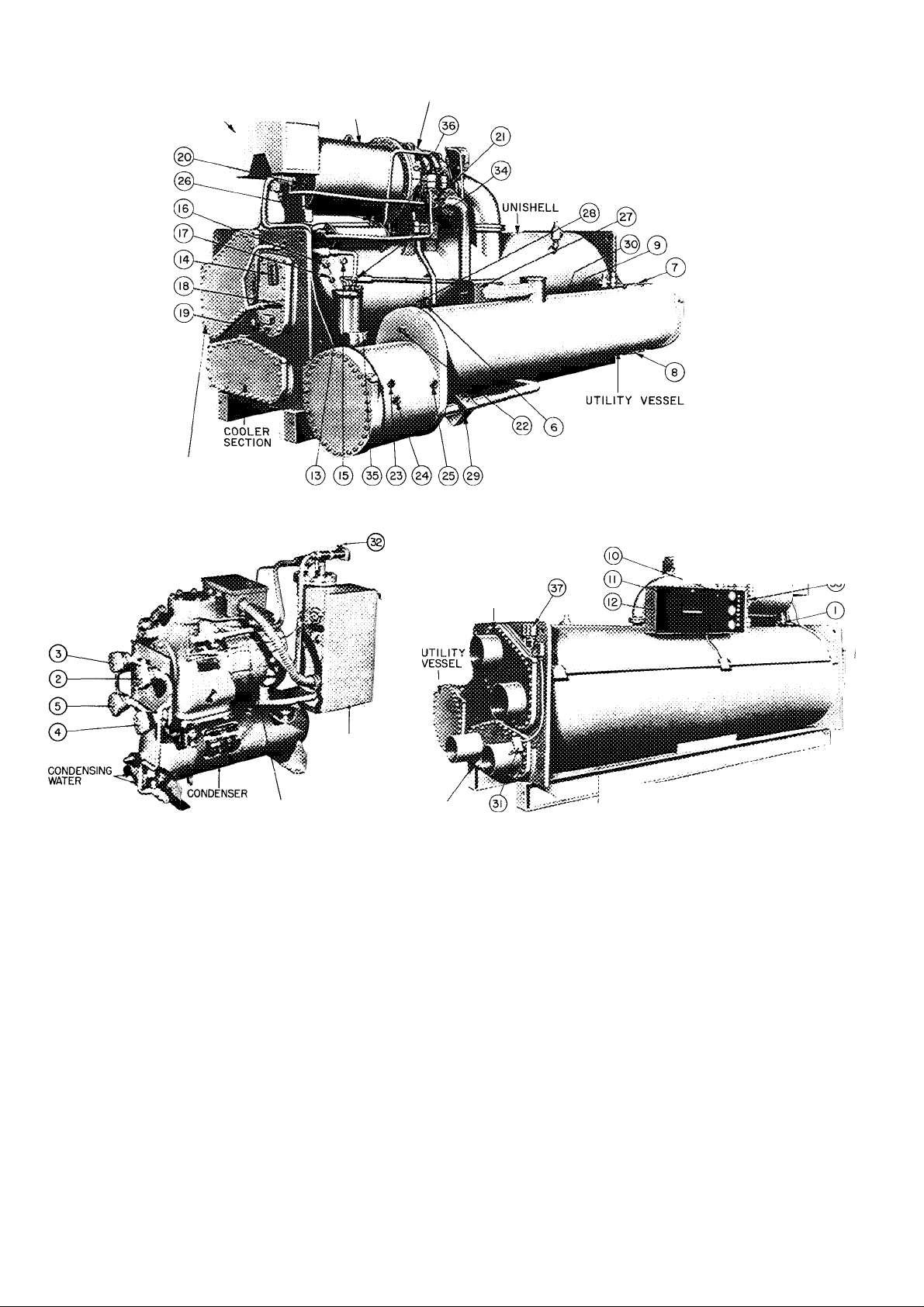
1 Pumpout Service Valve 1
2 Pumpout Service Valve 2
3 Pumpout Service Valve 3
4. Pumpout Service Valve 4
5 Pumpout Service Valve 5
6 Pumpout Service Valve 6 and Refrigerant Charging Valve
7. Pumpout Service Valve 7
8 Pumpout Service Valve 8
9. Service Valve 9 (hidden between unishell and utility vessel)
10 Differential Pressure Gage (oil)
11 Condenser Pressure Gage
12 Cooler Pressure Gage
13. Dehydrator Water Valve
14 Oil Level Sight Glass
15 Oil Temperature Gage
16 Oil Heater (with indicator light)
17. Oil Heater Thermostat
18 Oil Pressure Regulating Valve
19 Oil Reservoir Charging Valve
COOLER
LEGEND
CONDENSER
REAR VIEW
COMPRESSOR
FRONT VIEW
UNISHELL
20.
Sight Glass — Rotation
21.
Sight Glass — Seal Oil
22
Sight Glass — Liquid Level
23
Sight Glass — Liquid Level
24. Sight Glass — Liquid Level
25 Sight Glass — Liquid Level
Refrigerant Drain Valve
26
27. Isolation Valve
Isolation Valve (hidden)
28
29. Isolation Valve
Isolation Valve — ball valve between unishell
30.
and utility vessel (hidden)
31 Chilled Water Control Element
32 Pumpout Vent Valve with Flare Cap
33. Bearing Return Oil Thermometer (hidden)
34 Dehydrator Pressure Gage
35 Dehydrator Discharge Hand Valve
36. Oil Cooler Plug Cock
Chilled Water Lo-Temp Cutout
37
/ MOTOR DRIVE
Fig. 1 — Machine Components
Page 3
ISOLATION VALVE OPERATION
Opening — Compressor must be off and vessel
pressures equalized (see Return Refrigerant to
Normal Operating Condition, steps 1 thru 6).
^. Loosen packing nut 1/2 to 1 turn so valve stem
will rotate and slide smoothly in packing. Do
not let refrigerant trapped in valve body escape.
2. Hold stem in against line pressure and rotate
stem counterclockwise as far as possible.
3. Slide stem out of body.
4i Rotate stem clockwise in the out position, until
snug.
5. Tighten packing nut.
Closing
1. Loosen packing nut 1/2 to 1 turn so valve stem
will rotate and slide smoothly in packing. Do
not let refrigerant trapped in valve body escape.
2. Rotate valve stem counterclockwise as far as
possible.
3. Slide stem into valve until it bottoms.
4. Rotate stem clockwise, holding assembly in,
until it is tight (25 ft-lb).
5. Tighten packing nut.
TRANSFER REFRIGERANT FROM UTILITY
VESSEL TO UNI SHELL* from normal operating
condition.
1. Add manometer near charging valve 6.
2. Close isolation valves (27), (28), and (30).
3. Open valves 1, 3, 4, 6, 7 and 8.
4. Close valves 2, 5 and 9.
5. Ensure that pumpout condenser water is off.
6. Turn on pumpout compressor until liquid is
out of utility vessel.
7. Turn off pumpout compressor.
8. Close isolation valve (29).
9. Close valves 3 and 4.
10. Open valves 1,2, 5 and 6.
11. Turn on pumpout condenser water.
12. Run pumpout compressor until utility vessel
pressure reaches 25 in. Hg, ref 30-in. bar. (2.5
psia).
13. Turn off pumpout compressor.
14. Close valves 1, 2, 5 and 6.
15. Turn off pumpout condenser water.
TRANSFER REFRIGERANT FROM UNISHELL
TO UTILITY VESSEL* from normal operating
condition.
1. Open drain valve (26).
2. Wait one hour; close isolation valves (27), (28)
and (30).
3. Open valves 1,2, 5, 6, 7 and 8.
4. Close valves 3 and 4.
5. Ensure that pumpout condenser water is off.
6. Turn on pumpout compressor for 20 minutes.
7. Turn off pumpout compressor.
8. Close isolation valve (29).
Close valves 2 and 5.
10. Open valves 1, 3, 4 and 6.
11. Turn on cooler and condenser pumps and
pumpout condenser water.
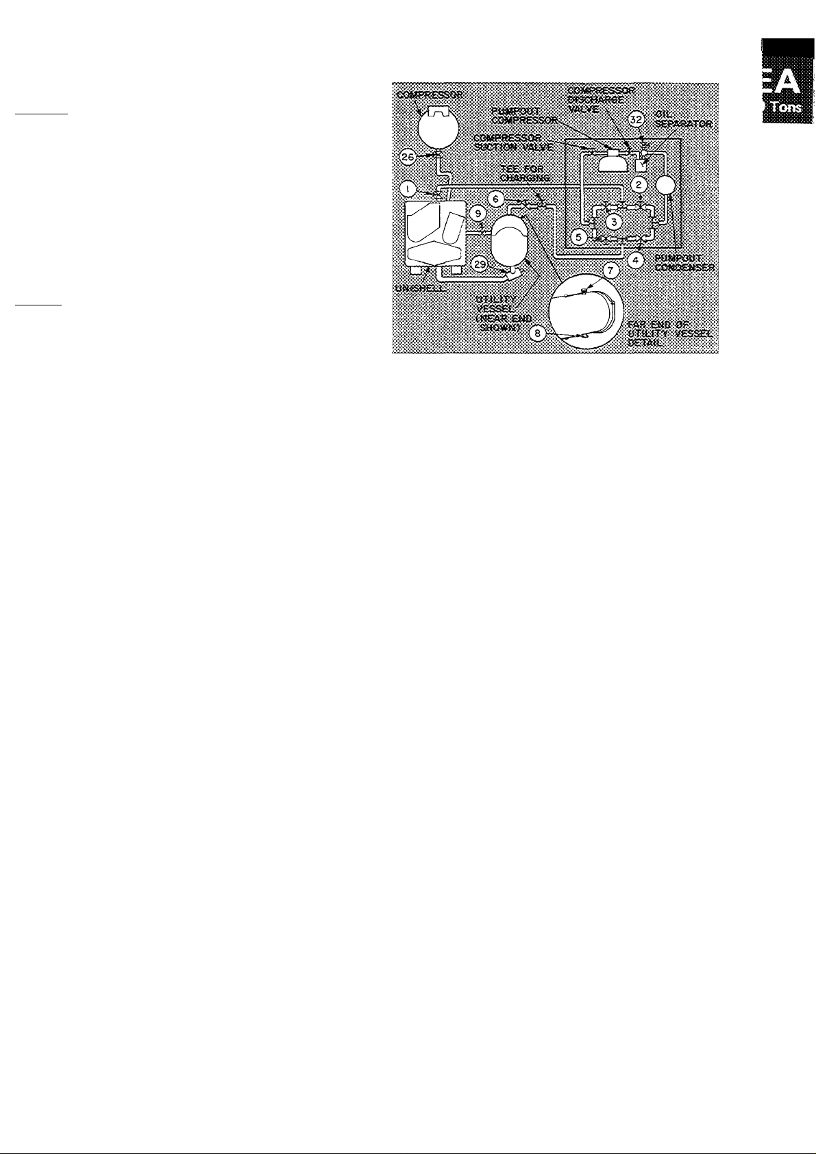
*See Fig 1 and 2 for all numbered references.
Fig. 2 — Pumpout System Schematic
(See Fig. 1 Legend for Item Ref)
12. Run pumpout compressor until unishell pres
sure reaches 25 in. Hg, ref 30-in. bar. (2.5
psia). Use dehydrator gage (34) for pressure
reading.
13. Turn off pumpout compressor.
14. Close valves 1, 3, 4 and 6.
15. Turn off pumpout condenser water.
UTILITY VESSEL EVACUATING PROCEDURE*
1. Close valves 1,2, 3, 4 and 9.
2. Open valves 5,6,1 and 8.
3. Open vent valve (32) and remove flare cap.
4. Turn off pumpout condenser water.
5. Operate pumpout compressor until manometer
reads 25 in. Hg, ref 30-in. bar. (2.5 psia).
6. Close valves 5, 6, 7 and 8.
7. Shut off pumpout compressor.
8. Close vent valve (32) and replace flare cap.
UNISHELL EVACUATING PROCEDURE*
1. Close valves 2, 4, 6 and 9.
2. Open valves 1, 3 and 5.
3. Open vent valve (32) and remove flare cap.
4. Turn off pumpout condenser water.
5. Operate pumpout compressor until manometer
reads 25 in. Hg, ref 30-in. bar. (2.5 psia).
6. Close valves 1, 3 and 5.
7. Shut off pumpout compressor.
8. Close vent valve (32) and replace flare cap.
RETURN REFRIGERANT TO NORMAL OPER
ATING CONDITION *
1. Ensure that opened vessel has been evacuated.
2. Close valves 3, 4 and 5.
3. Open valves 1,2, 6, 7 and 8.
4. Run water pumps.
5a. If unishell has been evacuated — Crack open
valve 4, gradually increasing pressure in uni
shell to 35 psig. Feed refrigerant slowly to
prevent tube freeze-up.
Page 4

b. If utility vessel has been evacuated — Crack
open valve 4 to gradually equalize pressure
between unishell and utility vessel. Ensure
that unishell pressure does not drop below 35
psig to prevent tube freeze-up.
6. Open valve 4 fully.
7. Open valve (29) to equalize the liquid refrig
erant levels between vessels.
8. Close valves 1,2, 3, 4, 5, 6, 7 and 8.
9. Open isolation valves (27), (28) and (30) and
service valve 9.
10. Close drain valve (26).
MACHINE DEHYDRATION — It is recommended
that the machine be dehydrated only if it has been
open for a considerable period of time, or if there
has been a complete loss of unishell holding charge
or utility vessel refrigerant charge.
WARNING; Do not staxt compressor ot oil
puH^ even, for a rotation check wliile machine
is under dehydration vacunm.
NOTE: Dehydration is readily accomplished at
normal room temperature. If room temperature is
high, dehydration takes place more quickly. At low
room temperatures, dehydration is extremely
difficult and special techniques must be applied.
Contact your Carrier representative for further
information.
Perform dehydration as follows:
1. Connect a dehydration pump to the refrigerant
charging valve (6) Fig. 1.
2. Connect a mercury manometer (absolute
pressure-type) to the dehydrator discharge hand
valve, (35) Fig. 1, and then open the valve. If
only the utility vessel is to be dehydrated, a tee
for the manometer must be provided between
the refrigerant charging valve and a valve on the
vacuum or dehydration pump.
3. Open the proper pumpout system valves to
evacuate the desired vessel(s).
4. Operate the dehydration pump until the
manometer reads 0.20 in. Hg abs (29.80 in. Hg,
ref 30-in. bar.); continue to operate pump for 2
more hours.
5. Close refrigerant charging valve; stop dehydra
tion pump; record manometer reading.
6. After a 2-hour wait, take another manometer
reading. If reading has not increased, dehydra
tion is complete. If reading has increased,
repeat steps 4 and 5.
7. If reading continues to rise after several dehy
dration attempts, suspect a machine leak. If this
is the case, pressurize the unit to approximately
8 to 10 psi with dry air or nitrogen. Locate and
repair leak. Then repeat dehydration procedure.
Inspect Piping — Refer to piping diagrams in job
data and inspect chilled water, condenser water,
and oil cooler water piping. Ensure that flow direc
tion is correct in all cases and that all specified
piping requirements are met.
CHECK WATER FLOW RATE - Ensure that
cooler and condenser water loop is full, with air
vented from high points. Water flow thru cooler
and condenser must meet job requirements.
Measure water pressure drop across the cooler and
condenser or across the pumps. Check to see that
water flow rates agree with design flow.
Oil cooler water supply should meet the follow
ing specifications:
Clean water
Max water temperature 85 F
Max inlet working pressure 100 psi
Water velocity in tube, ft/sec 10 max ~ 6 min
Water flow, gal./min 7 max -- 4 min
Water press, drop, psi diff 5 max — 2 min
Valves and/or controls Field supplied
Field Wiring — Prior to starting equipment, refer to
wiring diagrams in job data and check power
supply as follows:
1. Connect a voltmeter across power wires to
compressor motor starter and measure voltage.
Compare this reading with voltage rating on
compressor and starter nameplates.
WARNING: Do not attempt to check high
voltage supply without proper equipment.
Serious personal injury can result.
2. Compare ampere rating on starter nameplate
with ampere rating on.inotor nameplate.
3. Check voltage to the following components and
compare to nameplate values: oil pump starter,
pumpout compressor motor starter.
4. Check 120 volt supply to oil heater.
5. Test motor and its power lead insulation
resistance using a 500-volt insulation tester such
as a megohmmeter. Proceed as follows:
a. Open starter main disconnect switch.
b. Test the three phases of compressor motor,
phase to phase, and phase to ground, with
tester connected on the motor side of the
starter contactor in the starter. Take resist
ance readings at 10-second and 60-second
intervals for each phase.
c. Divide the 60-second resistance reading by
the 10-second reading. This gives polariza
tion ratio. The polarization ratio must be
1.15:1 or higher. The 10-second and
60-second resistance readings must be 5.0
megohms or higher.
If the readings are unsatisfactory, repeat the
tests at motor terminals with motor power leads
disconnected. This will indicate whether fault is in
motor or in motor power leads.
Check Starter — Before starting the 19EA, open
the main disconnect and then check starter:
1. Remove contactor arc chutes. Be sure con
tactors move freely, and that shipping string is
removed. Replace arc chutes.
2. If starter has been on jobsite for a considerable
period, check contactors for dirt and rust.
Clean contact magnet surfaces lightly with
sandpaper. Apply a very thin coat of vaseline to ^
magnet surfaces, then wipe it off. If starter haf
been in a dusty atmosphere, vacuum clean
starter cabinet and wipe with a lint-free cloth.
3. Remove fluid cups from magnetic overload
relays. Add dashpot oil to cups per instructions
add
Page 5

on relay nameplate. Oil is shipped in small vials
usually attached to starter frame near relays.
Use only the dashpot oil shipped with starter.
Do not substitute. Overload relays are factory
set for 108 percent of motor full load amper
age. Resetting is not normally required.
4. Check transfer timer for proper time setting.
On Star-Delta starters, timers have adjustable
ranges of 10 seconds to 3 minutes and are
factory set for one minute. On AutoTransformer starters, timers have adjustable
ranges of 0 to 60 seconds and are factory set
for 30 seconds.
5. With main disconnect switch open, manually
open and close main control relay (ICR) to be
sure it operates freely.
Oil Charge is shipped in the oil reservoir. Check
sight glass (14) to be certain oil is visible. If oil
must be added, it must meet Carrier’s oil specifi
cation. Charge oil thru the oil reservoir charging
valve (19). Use a hand pump to charge the oil
against machine pressure.
Oil Heater — Energize the oil heater to minimize
absorption of refrigerant by the oil. A light (16)
indicates when the heater is energized. Set the oil
heater thermostat to maintain a minimum
temperature of 145 F at shutdown.
Refrigerant Charge is shipped in the utility vessel.
If refrigerant must be added, charge it thru the
refrigerant charging valve (6).
WARNING; Never charge liquid refrigerant into
the unjshell if the pressure is helow 35 psig.
Bek>w 35 psig, R-12 will flash to a gas at a
temperature heiow the freezing pomt of water.
With cooler and condenser water fiownng,
charge the refrigerant as a gas tmiil the vessel
pressure is above 35 psig.
Refer to Trimming Refrigerant Charge for full
load adjustment.
Check Operation of Safety Controls — As the
following checks are made, the panel lights
should appear as shown in the diagrams.
CONTROL LIGHTS
STEP
□ -OFF
□ □
□
□ □
□
□ □
■ ■
□
□ □
□ □ □
□
□
2
1
■
□
□ □
3A
l-ON
■
□ □
□ □ □
□
□
■ ■
□ □
□ ■
□
□ □
3B 4 5
ON-STOP
■
START
OIL PUMP
□
POWER
■
SAFETY CIRCUIT
■
LOAD RECYCLE
PROGRAM TIMER
(SEE BELOW)
1. Disconnect main motor leads in starter.
2. Energize the control circuit.
3a. With water pumps off, press oil pump button
for several seconds to determine oil pressure
on differential gage. With pump running,
confirm that circuit between terminals
<Q> and ^ is closed by using an
ohmmeter.
b. Release the oil pump button. Circuit between
terminals ^ and must open.
4. Start the chilled water and condenser water
pumps. Confirm that circuit between terminals
and is closed with pumps run
ning, and opens when pumps stop and flow
switches open.
5. Press ON-STOP button. If safety circuit light is
off, check resets on the condenser highpressure safety, cooler low-pressure safety,
bearing and motor high-temperature circuit
breakers and compressor motor overloads in
starter. Check 3-amp fuse in control center. If
safety circuit light is on but load recycle light
is off, check the automatic resetting chilled
water recycle switch. If both lights are on,
manually trip and then reset bearing and
motor high-temperature circuit breakers and
compressor motor overloads to be sure they
cut off the safety light. Tripping the chilled
water recycle switch will cut off the load
recycle light only.
CONTROL LIGHTS
□ -OFF B-ON
ON-STOP
m
■
■
□
■
□
■
■
■
□
■
□
■
\m
□
START
□
OIL PUMP
□
POWER
■
SAFETY CIRCUIT
■
LOAD RECYCLE
■
PROGRAM TIMER
□
8 {SEE BELOW)
STEP
N
■
□
■
■
■
■
6A 6B 6C
6a. Press machine START button. (Motor leads
disconnected and water pumps running.)
b. Oil pump starts within 30 seconds.
c. Compressor motor start contacts will close 30
seconds later. Starter will transfer to its run
condition 30 to 60 seconds after starter is
energized.
7. Open the oil pump main disconnect. Starter
must de-energize. Close disconnect.
8. In approximately 15 minutes, the program
timer will complete the antirecycle portion of
its cycle and the machine may be started.
9. Open circuit breaker and reconnect main
motor leads.
START-UP
Preliminary Checks
1. Power on to main circuit breaker, control
circuit, water pumps and tower fan.
2. Cooling tower water level.
3. Oil reservoir level and refrigerant level.
4. Oil reservoir temperature 145 F or warmer.
5. All isolation valves open. See (27), (28), (29)
and (30) of Fig. 1. If valves are closed, follow
isolation valve procedure on page 3.
6. Oil cooler plug cock, (36) Fig. 1, cracked open,
and any other valves in oil cooler line fully
open.
Page 6

7. Valves in chilled water and condenser water
circuits open and water circulating properly. Do
not permit water warmer than 100 F to flow
thru cooler.
COMPRESSOR ROTATION — Set capacity control
(item 2, Fig. 3) to “Hold.” Press machine ON-STOP
and START buttons.
As soon as motor starts to turn, press machine
ON-STOP button. Check motor rotation thru sight
glass in motor end bell (Fig. 1). Motor rotation
must be clockwise when viewed from motor end. If
not, reverse any 2 of 3 power leads coming into
motor starter and recheck rotation.
COMPRESSOR OPERATION
Press machine ON-STOP and START buttons and
let compressor come up to speed. Press machine
ON-STOP button and listen for any unusual sounds
coming from the compressor and transmission
housing as compressor coasts to a stop.
Program timer prevents rapid recycling of com
pressor and allows restart-15 minutes after stop.
Checking Safety Control Settings
add
® © 0
LEGEND
1. Motor Current Calibration Adjustment
2. Capacity Control Switch
3. Electrical Demand Adjustment
4. Thermostat (chilled water)
5. Throttle Range Adjustment
6. Condenser High-Pressure Cutout Switch (manual reset)
7. Cooler Low-Pressure Cutout Switch (manual reset)
8. Program Timer
9. Motor High-Temperature Cutout (manual reset)
10. Bearing High-Temperature Cutout (manual reset)
11. Low Oil Pressure Cutout
12. Economizer-Cooler Differential Pressure Switch
© @
Fig. 3 — Control Center
Table 3 — Checking Safety Controls
Open main disconnect (all power off to starter
and controls). Set capacity control to “Hold.”
Place a clamp-on ammeter on one of the 3 starter
leads. Install jumper between [0] •
Close disconnect(s), start compressor and check oil
pressure and temperature (items 10 and 15, Fig. 1).
With compressor running, manually operate the
prewhirl vanes with the capacity control switch.
Do not exceed 100 percent full load amperage.
1. Set control 1 (chilled water low temperature
cutout) as indicated in Table 3.
2. Stop machine, open disconnect(s), remove
jumper and check controls 2 and 3 of Table 3.
3. Controls 4 and 5 do not require alteration of
factory settings. ;
4. Control 6 may require adjustment for operation
of unit at low design suction. Refer to Table 3.
SAFETY OR CONTROL DEVICE
1. Chilled Water Low-Temperature Cutout
and Recycle Switch (Fig. 1)
-TEMPERATURE ADJUSTMENT
2. Oil Heater Thermostat (Fig. 1)
"fcT'- / SCREW
LOCKING
SCREW
RECOMMENDED SETTING
1. Set this switch to break at approximately 5 F below design chilled water
temperature, or at 36 F, whichever is higher
2. Set the differential at 10F±1 F so that whep the machine shuts down
automatically at approximately 5 F below the design chilled water tempera
ture it will restart at approximately 5 F above the design water temperature.
3. This control must break ahead of the cooler low-pressure cutout or the
machine will not recycle automatically
Perform checks 2 and 3 with machine stopped and jumper removed
Set the oil heater thermostat to maintain a minimum oil reservoir temperature of
145 F at shutdown
.adjusting
»
Page 7

Table 3 — Checking Safety Controls (cont)
SAFETY OR CONTROL DEVICE
3. Low Oil Pressure Cutout (Fig. 3)
RANGE
DIAL ADJUSTMEN1?
REMOVE METAL
COVER
DIFFERENTIAL
4. Economizer Cooler Differentia! Pressure
Switch {Fig. 3)
OIL
PRESSURE
RECOMMENDED SETTING
Factory set to cut out at 13 ±1 psi differential Operate oil pump manually
Remove cap and gasket from regulating valve (item 18, Fig 1) Loosen locknut
Turn adjusting screw counterclockwise to lower oil pressure to 12 psi differential
If safety does not trip, turn range dial clockwise until cutout occurs Access to
control is thru knockout at rear of control box
The economizer-cooler differential pressure switch is factory set to energize the
refrigerant feed control at 10 psid
'<7
i. Condenser High-Pressure Cutout (Fig. 3)
Ù.
range
adjustment
SCREW
6. Cooler Low-Pressure Cutout (Fig. 3)
Setting Operating Controls
MOTOR CURRENT CALIBRATION
PROCEDURE
1. Establish a steady motor cun'ent value for this
calibration. Open guide vanes manually
(capacity control to “Inc”) until full load
current is reached. Motor current calibration
adjustment (item 1, Fig. 3) may have to be
turned counterclockwise to permit vanes to
open further. Do not exceed 105 percent of
nameplate full load amps
If building load is sufficient to maintain full
load current for a period of time, calibrate at
this condition. With small loads, pull down to
and maintain (capacity control to “Hold”)
The condenser high pressure switch is factory set to shut machine down when
condenser pressure reaches 161 ±5 psig Field calibration is not required
Cooler low-pressure switch is factory set at 32 ±2 psig If design suction
temperature is below 36 F, field resetting may be necessary With control power
off (power light out), install jumpers between terminals and 0 and
between and . Set switch to cut out at one degree below design
suction temperature Remove jumpers Restore power
design leaving chilled water temperature and
calibrate at this condition.
2. Measure motor current at selected condition.
Determine its percentage of full load motor
current.
3. Use this percentage figure to set the electrical
demand adjustment (item 3, Fig. 3) per the
following table:
Percent of Full
Load Motor Current
105
85 or above
65 to 84
45 to 64
below 45
Electrical Demand
Adjustment Setting
1ÜÜ pêrcêrvF ~
80 percent
60 percent
40 percent
Control cannot be
calibrated
Page 8

4. Turn the motor current calibration adjustment
fully clockwise. This will force the guide vanes
to close part way.
5. Turn the thermostat adjustment (item 4, Fig. 3)
to “Cooler” (fully counterclockwise).
6. Set the capacity control switch (item 2, Fig. 3)
to “Inc” position.
7. Slowly turn the motor current calibration
adjustment counterclockwise, allowing the
guide vanes to open until the motor current
reaches 5 percentage points above the electrical
demand setting.
NOTE: There is a time lag of several seconds
due to feedback capacitance in the motor
current circuit. When motor current calibration
setting is adjusted, this time lag should be
allowed for.
8. Check the foregoing motor current calibrations
with machine under “Auto” control as follows:
a. Close vanes manually (capacity control to
“Dec”).
b. Turn capacity control to “Auto.” Vanes
should stop opening at electrical demand
setting.
9. If control was calibrated at less than 100
percent load, turn electrical demand adjustment
setting to 100 percent. Control is now auto
matically calibrated for 100 percent full load
motor current.
This is a two-step motor current limiting
circuit. At 100 percent full load motor current,
the vanes will stop opening any further. If the
motor current should increase to 105 percent
due to some change in load cpnditions, the
vanes will close until the motor current is
reduced to about 102 percent. If the motor
current is reduced to 98 percent or below, the
control will respond to leaving chilled water
temperature. The electrical demand adjustment
allows the operator to reduce the maximum
current drawn by the motor, minimizing the
electrical demand rate during the off season
operation.
NOTE: If control cannot be calibrated with
above procedure, check voltage signal from
signal resistor in starter. At 100 percent full
load current, voltage between terminals 23 and
24 inside control panel must be 0.5 ± 0.1 volts.
If not in this range, check sizing of resistor in
starter.
CHILLED WATER CALIBRATION PROCEDURE
1. Turn throttle range calibration adjustment
(item 5, Fig. 3) fully clockwise.
2. Turn chilled water thermostat (item 4, Fig. 3)
until design chilled water temperature is main
tained. Mark thermostat at this position. If
capacity control vanes hunt, turn throttle range
calibration adjustment counterclockwise in
small increments until hunting ceases. Chilled
water thermostat may require resetting.
Trimming Refrigerant Charge — After the machine
has been placed in operation, it may be necessary
to adjust the refrigerant charge to obtain optimum
machine performance.
When machine full load is available, add o,
remove refrigerant slowly until the difference
between leaving chilled water temperature and the
cooler temperature reaches design conditions or
becomes a minimum. Shut the machine down and
allow refrigerant level to equalize between vessels.
Mark the level indicator (items 23, 24 or 25, Fig.
1) and maintain that shutdown refrigerant level.
IIMSTRUCTIIMG THE CUSTOMER OPERATOR
Be sure the operator carefully reads the 19EA
Operating and Maintenance Instructions.
Point out the following components; explain
their function and the system in which they are
used.
Compressor
Guide vanes, vane motor and linkage
Refrigerant-cooled motor
Transmission
Unishell
Cooler, condenser
Relief valve, isolation valves
Utility Vessel
Float chambers, sight glasses
Relief valves, charging valve
Dehydrator
Importance of proper operation
Valves and system operation
Sight glasses, gage
Lubrication System
Oil pump, cooler, filter
Solenoid, plug-cock
Heater, thermostat, temperature gage
Oil level and temperature
Pumpout System
Compressor, condenser, oil separator
Valve designation and cycle
Control System
Manual switches, gages and lights
Operating controls, safety controls
AuxiUary and special controls
Auxiliaries
Starter(s), pumps, cooling tower
Describe Refrigeration Cycle
Review Maintenance
Scheduled, extended shutdown
Importance of Log Sheet Record
Importance of water treatment
Check Operator Knowledge
Start-stop procedure
Safety and Operating Controls
Carrier Service
Advise operator of availability, and method of
ordering parts.
Review Operating and Maintenance Instructions.
Manufacturer reserves the right to change any product specifications without notice.
CARRIER AIR CONDITIONING COMPANY • SYRACUSE,
lEW YORK
Tatalnn Nn FS31-929
 Loading...