

Page 1

AquaEdge® 19DV
Two-Stage Back-to-Back Centrifugal Liquid
Chillers with PIC6 Controls and HFO R-1233zd(E)
50/60 Hz
Start-Up, Operation, and Maintenance
Instructions
SAFETY CONSIDERATIONS . . . . . . . . . . . . . . . . . . . . 2
INTRODUCTION . . . . . . . . . . . . . . . . . . . . . . . . . . . . . . 3
ABBREVIATIONS AND EXPLANATIONS . . . . . . . . . . 4
CHILLER FAMILIARIZATION (FIG. 1 AND 2) . . . . . . . 4
Chiller Information Nameplate . . . . . . . . . . . . . . . . . . 4
System Components . . . . . . . . . . . . . . . . . . . . . . . . . . 4
Evaporator . . . . . . . . . . . . . . . . . . . . . . . . . . . . . . . . . . 4
Condenser . . . . . . . . . . . . . . . . . . . . . . . . . . . . . . . . . . 4
Economizer. . . . . . . . . . . . . . . . . . . . . . . . . . . . . . . . . . 4
Motor-Compressor. . . . . . . . . . . . . . . . . . . . . . . . . . . . 4
Purge Unit . . . . . . . . . . . . . . . . . . . . . . . . . . . . . . . . . . . 4
Variable Frequency Drive (VFD) . . . . . . . . . . . . . . . . . 4
Refrigerant Lubrication System . . . . . . . . . . . . . . . . . 4
Chiller Control Panel . . . . . . . . . . . . . . . . . . . . . . . . . . 4
Purge Control Panel. . . . . . . . . . . . . . . . . . . . . . . . . . . 5
PIC6 Touch Screen HMI. . . . . . . . . . . . . . . . . . . . . . . . 5
REFRIGERATION CYCLE . . . . . . . . . . . . . . . . . . . . . . 7
REFRIGERANT LUBRICATION CYCLE . . . . . . . . . . . 8
Summary. . . . . . . . . . . . . . . . . . . . . . . . . . . . . . . . . . . . 8
Bearings . . . . . . . . . . . . . . . . . . . . . . . . . . . . . . . . . . . . 8
Inhibitor Reclaim System . . . . . . . . . . . . . . . . . . . . . . 9
Motor Cooling System . . . . . . . . . . . . . . . . . . . . . . . . . 9
VFD Cooling System . . . . . . . . . . . . . . . . . . . . . . . . . . 9
VFD . . . . . . . . . . . . . . . . . . . . . . . . . . . . . . . . . . . . . . . . 9
Purge System . . . . . . . . . . . . . . . . . . . . . . . . . . . . . . . . 9
CONTROLS . . . . . . . . . . . . . . . . . . . . . . . . . . . . . . . . . 12
Definitions. . . . . . . . . . . . . . . . . . . . . . . . . . . . . . . . . . 12
General . . . . . . . . . . . . . . . . . . . . . . . . . . . . . . . . . . . . 12
PIC6 System Components . . . . . . . . . . . . . . . . . . . . 12
START-UP/SHUTDOWN/
RECYCLE SEQUENCE. . . . . . . . . . . . . . . . . . . . . . 13
Local Start/Stop Control . . . . . . . . . . . . . . . . . . . . . . 13
Lubrication Control . . . . . . . . . . . . . . . . . . . . . . . . . . 13
Shutdown . . . . . . . . . . . . . . . . . . . . . . . . . . . . . . . . . . 15
BEFORE INITIAL START-UP . . . . . . . . . . . . . . . . . . . 15
Job Data Required . . . . . . . . . . . . . . . . . . . . . . . . . . . 15
Equipment Required . . . . . . . . . . . . . . . . . . . . . . . . . 15
Remove Shipping Packaging . . . . . . . . . . . . . . . . . . 15
Tighten All Gasketed Joints . . . . . . . . . . . . . . . . . . . 15
Check Chiller Tightness . . . . . . . . . . . . . . . . . . . . . . 15
Refrigerant Tracer . . . . . . . . . . . . . . . . . . . . . . . . . . . 18
Leak Test Chiller . . . . . . . . . . . . . . . . . . . . . . . . . . . . 18
Standing Vacuum Test . . . . . . . . . . . . . . . . . . . . . . . 18
Check the Installation . . . . . . . . . . . . . . . . . . . . . . . . 20
Inspect Wiring . . . . . . . . . . . . . . . . . . . . . . . . . . . . . . 20
Chiller Dehydration . . . . . . . . . . . . . . . . . . . . . . . . . . 20
Inspect Water Piping . . . . . . . . . . . . . . . . . . . . . . . . . 21
Check Safety Valves . . . . . . . . . . . . . . . . . . . . . . . . . .21
Check Purge Compressor Operation . . . . . . . . . . . .21
Ground Fault Troubleshooting . . . . . . . . . . . . . . . . . 22
Carrier Comfort Network® Interface . . . . . . . . . . . . .22
Inhibitor Charge . . . . . . . . . . . . . . . . . . . . . . . . . . . . . 23
Software Configuration . . . . . . . . . . . . . . . . . . . . . . . 23
Charge Unit with Refrigerant . . . . . . . . . . . . . . . . . . . 23
Field Set Up and Verification . . . . . . . . . . . . . . . . . . . 31
Perform a Controls Test
(Quick Calibration/Quick Test) . . . . . . . . . . . . . . .32
INITIAL START-UP . . . . . . . . . . . . . . . . . . . . . . . . . . . 33
Preparation . . . . . . . . . . . . . . . . . . . . . . . . . . . . . . . . .33
Check Motor Rotation. . . . . . . . . . . . . . . . . . . . . . . . . 33
Check Refrigerant Lube . . . . . . . . . . . . . . . . . . . . . . . 33
To Prevent Accidental Start-Up . . . . . . . . . . . . . . . . . 33
Check Chiller Operating Condition . . . . . . . . . . . . . .33
Instruct the Customer Operator(s) . . . . . . . . . . . . . . 34
OPERATING INSTRUCTIONS. . . . . . . . . . . . . . . . . . .36
Operator Duties. . . . . . . . . . . . . . . . . . . . . . . . . . . . . . 36
Prepare the Chiller for Start-Up . . . . . . . . . . . . . . . . . 36
To Start the Chiller . . . . . . . . . . . . . . . . . . . . . . . . . . . 36
Check the Running System . . . . . . . . . . . . . . . . . . . . 36
To Stop the Chiller . . . . . . . . . . . . . . . . . . . . . . . . . . .36
After Limited Shutdown . . . . . . . . . . . . . . . . . . . . . . . 36
After Extended Shutdown . . . . . . . . . . . . . . . . . . . . . 36
Cold Weather Operation. . . . . . . . . . . . . . . . . . . . . . .37
Manual Guide Vane Operation. . . . . . . . . . . . . . . . . .37
Refrigeration and Service Log. . . . . . . . . . . . . . . . . .37
PUMPOUT AND REFRIGERANT
TRANSFER PROCEDURES . . . . . . . . . . . . . . . . . .39
Preparation . . . . . . . . . . . . . . . . . . . . . . . . . . . . . . . . .39
GENERAL MAINTENANCE. . . . . . . . . . . . . . . . . . . . . 42
Refrigerant Properties . . . . . . . . . . . . . . . . . . . . . . . .42
Adding Refrigerant . . . . . . . . . . . . . . . . . . . . . . . . . . . 42
Adjusting the Refrigerant Charge . . . . . . . . . . . . . . . 42
Refrigerant Leak Testing . . . . . . . . . . . . . . . . . . . . . .42
Leak Rate . . . . . . . . . . . . . . . . . . . . . . . . . . . . . . . . . . . 42
Test After Service, Repair, or Major Leak. . . . . . . . .42
Repair Leaks, Retest, Standing Vacuum Test . . . . .42
Checking Guide Vanes . . . . . . . . . . . . . . . . . . . . . . . . 42
Trim Refrigerant Charge. . . . . . . . . . . . . . . . . . . . . . . 44
WEEKLY MAINTENANCE . . . . . . . . . . . . . . . . . . . . . .44
Check the Refrigerant Lubrication System . . . . . . . 44
Check for Leaks . . . . . . . . . . . . . . . . . . . . . . . . . . . . .44
SCHEDULED MAINTENANCE . . . . . . . . . . . . . . . . . .44
Service Ontime . . . . . . . . . . . . . . . . . . . . . . . . . . . . . . 44
Inspect the Control Panel. . . . . . . . . . . . . . . . . . . . . . 44
Inspect the Purge . . . . . . . . . . . . . . . . . . . . . . . . . . . . 45
Catalog No. 04-53190056-01 Printed in U.S.A. Form 19DV-CLT-2SS Pg 1 6-19 Replaces: 19DV-CLT-1SS
Manufacturer reserves the right to discontinue, or change at any time, specifications or designs without notice and without incurring obligations.
Page 2

Changing Refrigerant Lubrication Filters . . . . . . . . 45
Inspect Refrigerant Float System . . . . . . . . . . . . . . . 45
Inspect Safety Relief Devices and Piping . . . . . . . . 45
Compressor Bearing Maintenance . . . . . . . . . . . . . . 46
Inspect the Heat Exchanger Tubes
and Flow Devices . . . . . . . . . . . . . . . . . . . . . . . . . . 46
Water Leaks . . . . . . . . . . . . . . . . . . . . . . . . . . . . . . . . 46
Water Treatment . . . . . . . . . . . . . . . . . . . . . . . . . . . . . 46
Inspect the VFD . . . . . . . . . . . . . . . . . . . . . . . . . . . . . 46
Recalibrate Pressure Transducers . . . . . . . . . . . . . . 47
Recalibrate Temperature Thermistors . . . . . . . . . . . 47
Ordering Replacement Chiller Parts . . . . . . . . . . . . . 47
TROUBLESHOOTING GUIDE. . . . . . . . . . . . . . . . . . . 47
Overview . . . . . . . . . . . . . . . . . . . . . . . . . . . . . . . . . . . 47
Checking Display Messages . . . . . . . . . . . . . . . . . . . 47
Checking Temperature Sensors . . . . . . . . . . . . . . . . 47
Checking Pressure Transducers . . . . . . . . . . . . . . . 50
High Altitude Locations . . . . . . . . . . . . . . . . . . . . . . . 51
Quick Test . . . . . . . . . . . . . . . . . . . . . . . . . . . . . . . . . . 51
Quick Calibration . . . . . . . . . . . . . . . . . . . . . . . . . . . . 51
Pumpdown/Lockout . . . . . . . . . . . . . . . . . . . . . . . . . . 51
Physical Data . . . . . . . . . . . . . . . . . . . . . . . . . . . . . . . 51
APPENDIX A — PIC6 SCREEN AND MENU
STRUCTURE
APPENDIX B — CCN COMMUNICATION WIRING
FOR MULTIPLE CHILLERS (TYPICAL) . . . . . . 75
APPENDIX C — MAINTENANCE SUMMARY AND
LOG SHEETS . . . . . . . . . . . . . . . . . . . . . . . . . . 76
APPENDIX D — REMOTE CONNECTIVITY
COMMISSIONING . . . . . . . . . . . . . . . . . . . . . . . . . . 77
INDEX. . . . . . . . . . . . . . . . . . . . . . . . . . . . . . . . . . . . . . 81
INITIAL START-UP CHECKLIST . . . . . . . . . . . . . . CL-1
. . . . . . . . . . . . . . . . . . . . . . . . 72
SAFETY CONSIDERATIONS
Centrifugal liquid chillers are designed to provide safe and reliable service when operated within design specifications. When
operating this equipment, use good judgment and safety precautions to avoid damage to equipment and property or injury
to personnel.
Be sure you understand and follow the procedures and safety
precautions contained in the chiller instructions as well as
those listed in this guide.
DANGER
Failure to follow these procedures will result in severe personal injury or death.
DO NOT VENT refrigerant relief valves within a building.
Outlet from rupture disc or relief valve must be vented outdoors in accordance with the latest edition of ANSI/
ASHRAE 15 (American National Standards Institute/
American Society of Heating, Refrigerating, and AirConditioning Engineers). The accumulation of refrigerant
in an enclosed space can displace oxygen and cause
asphyxiation.
PROVIDE adequate ventilation in accordance with ANSI/
ASHRAE 15, especially for enclosed and low overhead
spaces. Inhalation of high concentrations of vapor is harmful and may cause heart irregularities, unconsciousness, or
death. Misuse can be fatal. Vapor is heavier than air and reduces the amount of oxygen available for breathing. Product causes eye and skin irritation. Decomposition products
are hazardous.
DO NOT USE OXYGEN to purge lines or to pressurize a
chiller for any purpose. Oxygen gas reacts violently with
oil, grease, and other common substances.
NEVER EXCEED specified test pressures; VERIFY the allowable test pressure by checking the instruction literature
and the design pressures on the equipment nameplate.
DO NOT USE air for leak testing. Use only refrigerant or
dry nitrogen.
DO NOT VALVE OFF any safety device.
BE SURE that all pressure relief devices are properly in-
stalled and functioning before operating any chiller.
RISK OF INJURY OR DEATH by electrocution. High
voltage can be present on motor leads even though the motor is not running. Open the power supply disconnect before touching motor leads or terminals.
WARNING
Failure to follow these procedures may result in personal
injury or death.
DO NOT USE TORCH to remove any component. System
contains refrigerant which may be under pressure.
To remove a component, wear protective gloves and goggles and proceed as follows:
a. Shut off electrical power to unit.
b. Recover or isolate refrigerant from system using high-
pressure and low pressure ports as appropriate. Note that
R-1233zd(E) will be less than atmospheric pressure
until a temperature of about 65°F (18.5°C).
c. Traces of vapor should be displaced with nitrogen and
the work area should be well ventilated. Refrigerant in
contact with an open flame produces toxic gases.
d. Cut component connection tubing with tubing cutter
and remove component from unit.
e. Carefully unsweat remaining tubing stubs when necessary.
DO NOT USE eyebolts or eyebolt holes to rig chiller sections or the entire assembly.
DO NOT work on high-voltage equipment unless you are a
qualified electrician.
DO NOT WORK ON electrical components, including
control panels, switches, or starters, until you are sure ALL
POWER IS OFF and no residual voltage can leak from capacitors or solid-state components.
(Warnings continued on next page.)
2
Page 3

WARNING
LOCK OPEN AND TAG electrical circuits during servicing. IF WORK IS INTERRUPTED, confirm that all circuits are de-energized before resuming work.
AVOID SPILLING liquid refrigerant on skin or getting it
into the eyes. USE SAFETY GOGGLES. Wash any spills
from the skin with soap and water. If liquid refrigerant enters the eyes, IMMEDIATELY FLUSH EYES with water
and consult a physician.
NEVER APPLY an open flame or live steam to a refrigerant cylinder. Dangerous overpressure can result. When it is
necessary to heat refrigerant, use only warm (110°F [43°C])
water.
VERIFY that refrigerant storage cylinders are clean with no
residual moisture, oil, or refrigerant that can contaminate
the refrigerant charge.
DO NOT REUSE disposable (nonreturnable) cylinders or
attempt to refill them. It is DANGEROUS AND ILLEGAL. When cylinder is emptied, evacuate remaining gas
pressure, loosen the collar, and unscrew and discard the
valve stem. DO NOT INCINERATE.
CHECK THE REFRIGERANT TYPE before adding refrigerant to the chiller. The introduction of the wrong refrigerant can cause damage or malfunction to this chiller.
Operation of this equipment with refrigerants other than
those cited herein should comply with ANSI/ASHRAE 15
(latest edition). Contact Carrier for further information on
use of this chiller with other refrigerants.
DO NOT ATTEMPT TO REMOVE fittings, covers, etc.,
while chiller is refrigerant charged or at any time while
chiller is running. Be sure pressure is at 0 psig (0 kPa) before breaking any refrigerant connection. Note that chiller
will be in a vacuum condition when temperature is below
normal room temperature.
CAREFULLY INSPECT all rupture discs and other relief
devices AT LEAST ONCE A YEAR. If chiller operates in a
corrosive atmosphere, inspect the devices at more frequent
intervals.
DO NOT ATTEMPT TO REPAIR OR RECONDITION
any relief device when corrosion or build-up of foreign material (rust, dirt, scale, etc.) is found within the valve body
or mechanism. Replace the device.
DO NOT install relief devices in series or backwards.
USE CARE when working near or in line with a com-
pressed spring. Sudden release of the spring can cause it
and objects in its path to act as projectiles.
CAUTION
Failure to follow these procedures may result in personal
injury or damage to equipment.
DO NOT STEP on refrigerant lines. Broken lines can whip
about and release refrigerant, causing personal injury.
DO NOT climb over a chiller. Use platform, catwalk, or
staging. Follow safe practices when using ladders.
USE MECHANICAL EQUIPMENT (crane, hoist, etc.) to
lift or move inspection covers or other heavy components.
Even if components are light, use mechanical equipment
when there is a risk of slipping or losing your balance.
BE AWARE that certain automatic start arrangements CAN
ENGAGE THE STARTER, TOWER FAN, OR PUMPS.
Open the disconnect ahead of the starter, tower fans, or
pumps.
USE only repair or replacement parts that meet the code requirements of the original equipment.
DO NOT VENT OR DRAIN waterboxes containing industrial brines, liquid, gases, or semisolids without the permission of your process control group.
DO NOT LOOSEN waterbox cover bolts until the waterbox has been completely drained.
DO NOT LOOSEN a packing gland nut before checking
that the nut has a positive thread engagement.
PERIODICALLY INSPECT all valves, fittings, and piping
for corrosion, rust, leaks, or damage.
PROVIDE A DRAIN connection in the vent line near each
pressure relief device to prevent a build-up of condensate or
rain water.
DO NOT leave refrigerant system open to air any longer than
the actual time required to service the equipment. Seal circuits
being serviced and charge with dry nitrogen to prevent contamination when timely repairs cannot be completed.
INTRODUCTION
Prior to initial start-up of the 19DV unit, those involved in the
start-up, operation, and maintenance should be thoroughly familiar with these instructions and other necessary job data.
Procedures in this manual are arranged in the sequence required for proper chiller start-up and operation. This book also
outlines the control system for those involved in the start-up,
operation and maintenance of the unit before performing startup procedures. It is intended to be used in combination with the
19DV Semi-Hermetic Centrifugal Liquid Chillers Controls
Operation and Troubleshooting manual that describes the controls in detail.
CAUTION
Do NOT punch holes or drill into the top surface of the control or VFD enclosure for field wiring. Knockouts are provided for field wiring connections. Drilling holes through
the top of the cabinet can result in a loss of warranty on the
starter assembly because of metal particulate falling on and
into electronic components.
CAUTION
PROVIDE MACHINE PROTECTION. Store machine and
starter indoors, protected from construction dirt and moisture. Inspect under shipping tarps, bags, or crates to be sure
water has not collected during transit. Keep protective shipping covers in place until machine is ready for installation.
Follow latest Water-Cooled Chillers Long Term Storage
document located in Chiller Builder Library.
3
Page 4

CAUTION
WHEN FLUSHING THE WATER SYSTEMS isolate the
chiller from the water circuits to prevent damage to the heat
exchanger tubes.
CAUTION
This unit uses a microprocessor control system. Do not
short or jumper between terminations on circuit boards or
modules; control or board failure may result.
Be aware of electrostatic discharge (static electricity) when
handling or making contact with circuit boards or module
connections. Always touch a chassis (grounded) part to
dissipate body electrostatic charge before working inside
control center or use a grounding strap before handling
printed circuit boards.
Use extreme care when handling tools near boards and when
connecting or disconnecting terminal plugs. Circuit boards can
easily be damaged. Always hold boards by the edges and
avoid touching components and connections.
This equipment uses, and can radiate, radio frequency energy. If not installed and used in accordance with the instruction manual, it may cause interference to radio communications. The PIC6 control boards have been tested and found to
comply with the limits for a Class A computing device pursuant to International Standard in North America EN 610002/3 which are designed to provide reasonable protection
against such interference when operated in a commercial environment. Operation of this equipment in a residential area
is likely to cause interference, in which case the user, at his
own expense, will be required to take whatever measures
may be required to correct the interference.
Always store and transport replacement or defective boards
in anti-static shipping bag.
ABBREVIATIONS AND EXPLANATIONS
Frequently used abbreviations in this manual include:
AWG — American Wire Gage
BMS — Building Management System
CCN — Carrier Comfort Network
DCIB — Digital Control Interface Board
DVM — Digital Volt-Ohmmeter
EC — Envelope Control
ECDW — Entering Condenser Water
ECW — Entering Chilled Water
EMS — Energy Management System
HMI — Human Machine Interface
HVIB — High Voltage Interface Board
I/O — Input/Output
IGBT — Insulated-Gate Bipolar Transistor
IGV — Inlet Guide Vane
IOB — Input Output Board
LCDW — Leaving Condenser Water
LCW — Leaving Chilled Water
LED — Light-Emitting Diode
MAWP — Maximum Allowable Working Pressure
NSTV — Network Service Tool V
OLTA — Overload Trip Amps
PIC — Product Integrated Controls
PPE — Protective Personal Equipment
PWM — Pulse Width Modulating
RLA — Rated Load Amps
RMS — Root Mean Square
SCCR — Short Circuit Current Rating
SCR — Silicon Controlled Rectifier
SIOB — Starfire 2 Input Output Board
TXV — Thermostatic Expansion Valve
VFD — Variable Frequency Drive
VPF — Variable Primary Flow
Factory-installed additional components are referred to as options
in this manual; factory-supplied but field-installed additional components are referred to as accessories.
®
CHILLER FAMILIARIZATION (Fig. 1 and 2)
Chiller Information Nameplate
The information nameplate is located on the left side of the
chiller control panel.
System Components
The main components include the evaporator and condenser
heat exchangers in separate vessels, motor-compressor, refrigerant, lubrication package, control panels, PIC6 Touch Screen
HMI, economizer, VFD, and purge system.
Evaporator
This vessel is located underneath the compressor. The evaporator is maintained at a lower temperature/pressure so evaporating refrigerant can remove heat from water flowing through its
internal tubes. Water flows through the internal tubes to provide comfort or process cooling.
Condenser
The condenser operates at a higher temperature/pressure than the
evaporator and has water flowing through its internal tubes in order to remove heat from the refrigerant. It contains a metering device that regulates the flow of refrigerant into the economizer.
Economizer
This chamber reduces the refrigerant pressure to an intermediate
level between the evaporator and condenser vessels. In the economizer, vapor is separated from the liquid, the separated vapor
flows to the second stage of the compressor, and the liquid flows
into the evaporator. The energy removed from the vaporized refrigerant in the economizer allows the liquid refrigerant in the
evaporator to absorb more heat when it evaporates and benefits
the overall cooling efficiency cycle. It contains a float assembly
that regulates the flow of refrigerant into the evaporator.
Motor-Compressor
This component maintains system temperature and pressure
differences and moves the heat-carrying refrigerant from the
evaporator to the condenser. The 19DV utilizes a two-stage
back to back direct drive configuration.
Purge Unit
This is a small independent condensing unit with compressor, separator, regenerative carbon filters, heater and vacuum pump. The
purge extracts gas from condenser (or from compressor if unit is
not in operation) and purifies it by removing non-condensable
gases and any water vapor that may be present.
Variable Frequency Drive (VFD)
The VFD variable frequency is a voltage source design that
converts line voltage into PWM (pulse width modulating) motor input for motor speed and torque control.
Refrigerant Lubrication System
This system provides lubrication to the compressor bearing by
means of a refrigerant pump.
Chiller Control Panel
This control panel includes the input and output boards (IOBs),
control transformer, relays, contactors, and circuit breakers. It provides the power distribution and protection to the electrical components installed on chiller and has the following functions:
• Communication with PIC6 touch screen
• Communication with purge panel
• Communication with VFD
• Sensor input and outputs
• Actuators control
• Refrigerant pump control
4
Page 5

Purge Control Panel
Description
19 —
High Efficiency Semi-Hermetic
Centrifugal Chiller
19 G 4
DV
–
V — Variable Speed Drive
Evaporator Frame Size, Length,
Pass Arrangement, and Tube Count
4
4
G
4
4
Condenser Frame Size, Length,
Pass Arrangement, and Tube Count
44
Compressor Frame Size
Compressor Impeller Diameter Code
Motor Voltage Code
Code Volts-Phase-Hertz
3 — 380-3-60
4 — 416-3-60
5 — 460-3-60
9 — 400-3-50
Special Order Indicator
– — Standard
S — Special Order
VFD Code*
5 — 850 Amp Std Tier VFD
5
H4
Compressor Shroud Code
3 — Smallest shroud
4 — Small-Mid shroud
5 — Mid-Large shroud
6 — Largest shroud
Motor Code*
B — Smallest HP
D — Small-Mid HP
F — Mid-Large HP
H — Largest HP
2 — Small diameter
4 — Large diameter
G20 - G4K — Frame G
H20 - H4K — Frame H
G22 - G4K — Frame G
H22 - H4K — Frame H
*Refer to 19DV NG E-Cat Builder
for motor and VFD size details.
4 — 500-800 nominal tons (1758-2813 kW)
D — Low Pressure
The purge panel includes the input and output boards, control
transformer, relays, and fuse. It provides the power distribution
and protection to the electrical components which installed in
the purge system and has the following functions:
• Communication with PIC6 touch screen
• Sensor input and outputs
• Solenoid valve control
• Control of purge compressor, vacuum pump, heater, and fan.
PIC6 Touch Screen HMI
This panel is the user interface for controlling the chiller and
has the following functions:
• Chiller operation
• Chiller diagnostic
• Chiller status display
• Chiller parameter configuration
• Provide open protocol interface to outside BMS (Building Management System)
Week of Year
Ye ar of Manufacture
Fig. 1 — 19DV Chiller Model Number Identification
SERIAL NUMBER STRUCTURE
12 17 Q 26788
Unique Number
Place of Manufacture
a19-2271
5
Page 6

1
1—Interconnecting Compressor Piping
2—VFD Drain (Field Drain Piping Required)
3—Condenser
4—Condenser Waterbox Return End
5—Economizer Isolation Valve (Option)
6—Economizer
7—Evaporator Waterbox Return End
8—Vacuum/Charging Valve (Hidden)
9—PIC6 HMI Touchscreen Panel
10 — Evaporator Bundle Sight Glasses
11 — Rupture Disc
12 — Suction Elbow
13 — Evaporator Charging Valve and
Evaporator Pressure Transducer
14 — First Stage Guided Vane Actuator
15 — Compressor Motor
16 — Moisture Indicator (Hidden)
17 — Evaporator
18 — Second Stage Guided Vane Actuator
19 — Evaporator Waterbox Nozzles
20 — Condenser Waterbox Nozzles
21 — Condenser Pressure Transducer
22 — Condenser Charging Valve
23 — Envelope Stability Control Pipe
24 — Purge Assembly
25 — Purge Vent (Hidden)
26 — Motor VFD Cooling Moisture Indicator
(Hidden)
27 — Control Panel
28 — Chiller Name Plate Label
29 — Lubrication Assembly
30 — Economizer Pipe
31 — VFD
32 — Discharge Pipe
2
FRONT VIEW
18
19
17
30
16
15
14
13
12
31
3
4
5
6
11
10
9
32
8
7
REAR VIEW
20
21
22
29
28
23
24
25
26
27
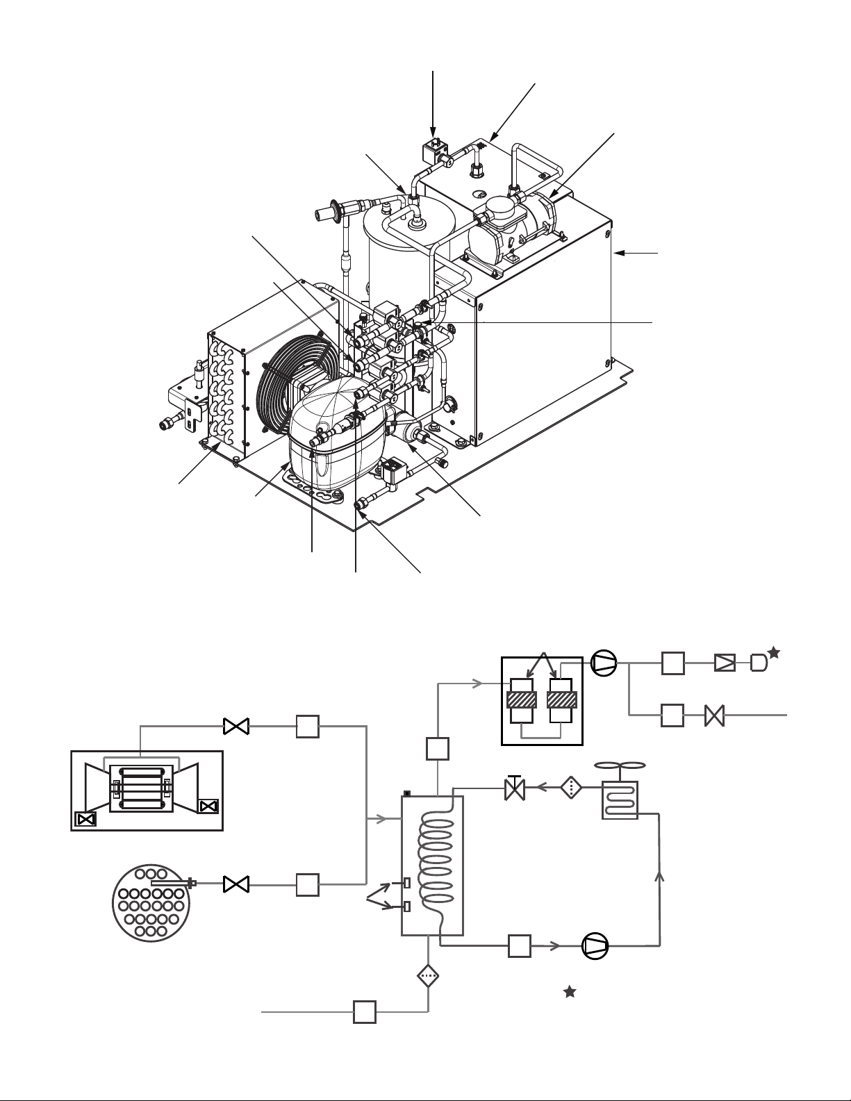
Fig. 2 — Typical 19DV 500-800 Ton Two-Stage Compressor Chiller Components
(DV4 Shown)
6
Page 7

REFRIGERATION CYCLE
HIGH SIDE FLOAT
CHAMBER
COOLER
ECONOMIZER
LOW SIDE
FLOAT CHAMBER
CONDENSER
COMPRESSOR
The compressor continuously draws refrigerant vapor from the
evaporator at a rate set by the amount of first stage guide vane
opening and motor speed. As the compressor suction reduces
the pressure in the evaporator, the remaining refrigerant boils
at a fairly low temperature (typically 38 to 42°F [3 to 6°C]).
The energy required for boiling is obtained from the water
flowing through the evaporator tubes. With heat energy removed, the water becomes cold enough to use in an air-conditioning circuit or process liquid cooling.
After taking heat from the water, the refrigerant vapor is compressed by a back-to-back compression connected by means of interstage piping. Compression adds heat energy and the refrigerant
is quite warm (typically 98 to 102°F [37 to 40°C]) when it is discharged from the compressor into the condenser.
Relatively cool (typically 65 to 90°F [18 to 32°C]) water flowing into the condenser tubes removes heat from the refrigerant,
and the vapor condenses to liquid. The liquid drains into a high
side float valve chamber between the condenser and the economizer. The refrigerant is then metered into the economizer. In
the economizer, due to lower pressure, as liquid enters the
chamber, some liquid will flash into a vapor and cool the remaining liquid. The separated vapor flows to the second stage
of the compressor for greater cycle efficiency. The second
stage guide vane on the compressor acts as a pressure regulating device to stabilize operating conditions. At part load the
second stage guide vane will back up gas flow and thereby
raises the economizer pressure to allow appropriate refrigerant
flow from economizer to the compressor.
The cooled liquid left in the economizer flows through a low
side float valve and then into the evaporator. The float valve
forms a liquid seal to keep vapor from entering the evaporator.
The refrigerant is now at a temperature and pressure at which the
cycle began. Figure 3 summarizes the refrigeration cycle.
The 19DV unit utilizes R-1233zd(E) refrigerant. At atmospheric pressure its boiling point is 65.5°F (18.6°C). The result is
that at normal operating conditions the evaporator typically
will be in a vacuum condition and the condenser will operate at
a pressure above atmospheric pressure. Unit near room temperature will be close to atmospheric pressure.
Fig. 3 — Refrigeration Cycle — 19DV Two-Stage Compressor
7
Page 8

CAUTION
PURGE SYSTEM
CONDENSER
HIGH SIDE FLOAT
CHAMBER
REFRIGERANT
LUBRICATION
SYSTEM
VENT LINE
COOLER
ECONOMIZER
LOW SIDE
FLOAT CHAMBER
COMPRESSOR
EDUCTOR
= PURGE
= LUBE SYSTEM
= MAIN REFRIGERANT SYSTEM
LEGEND
To avoid adverse effects on chiller operation, considerations
must be made to condenser water temperature control. For
steady state operation, the minimum operating refrigerant
pressure differential between evaporator and condenser is approximately 7 psid (48 kPa) with a maximum evaporator refrigerant temperature of 65°F (18°C). Consult Chiller Builder for required steady state operational limits and low lift options. Inverted start conditions are acceptable for short
durations of time, but for periods exceeding 5 minutes, a special control solution strategy should be used to allow the
chiller to establish a minimum refrigerant pressure differential (and thereby adequate equipment cooling).
REFRIGERANT LUBRICATION CYCLE
Summary
The 19DV Series chiller uses refrigerant to lubricate the bearings.
The lubrication control is automatically controlled by the chiller
controls. In normal RUN mode refrigerant is pumped by means of
a refrigerant pump from the high side condenser float chamber to
the bearings. Prior to start-up, liquid level in the high side condenser float chamber is maintained by pumping refrigerant liquid
from the evaporator to the high side float chamber until level sensor is satisfied. If liquid high side float level is not satisfied, the
pump will move refrigerant from the evaporator to the condenser.
During pre-lube and post-lube cycles, refrigerant is drawn from
the evaporator for bearing lubrication.
Figures 4 and 5 identify the refrigerant lubrication assembly. Supply refrigerant is pulled through a filter drier by the refrigerant
pump and is pumped to the bearings through two protective filters
and then returned to the evaporator.
There are two pressure sensors located across the refrigerant
pump. During RUN mode a minimum of 12 psid is required for
the refrigerant pump delta difference. An alert will trigger if
this value is less than 13 psid while the machine is in normal
operating mode. Consult the 19DV with PIC6 Controls Operation and Troubleshooting manual for details.
Bearings
The 19DV motor-compressor assembly includes two matched
sets of refrigerant-lubricated bearings. The motor shaft is supported by a combination set of journal bearing and roller element bearings on each end of compressor. The refrigerant lubrication pressure difference is defined as the bearing input
pressure minus the bearing output pressure plus the Refrigerant
Delta P Offset.
Fig. 4 — Refrigerant Lubrication Cycle
8
Page 9

STRAINER
PUMP
PUMP
SUCTION
DISCHARGE
ACTUATOR
Fig. 5 — Refrigerant Lubrication Assembly
Inhibitor Reclaim System
The inhibitor reclaim system moves inhibitor from the evaporator
and returns it to the first stage suction inlet which allows it to be
mixed in the system since it has a tendency to have higher concentration in the evaporator compared with the rest of the system. The
reclaim is powered by an eductor driven by the gas pressure difference between first stage suction and discharge of second stage.
Motor Cooling System
The motor is cooled by liquid refrigerant taken from the bottom of the high side condenser float chamber. Refrigerant flow
is maintained by the pressure differential that exists due to
compressor operation. After the refrigerant flows past an isolation valve, an in-line filter drier, and a sight glass/moisture indicator, it is directed over the motor by spray nozzles. The refrigerant collects in the bottom of the motor casing and is then
drained back into the evaporator through the motor refrigerant
drain line. The motor is protected by temperature thermistors
embedded in the stator windings. An increase in motor winding temperature past the motor override set point overrides the
temperature capacity control to hold, and if the motor temperature exceeds 10°F (5.5°C) above this set point, the controls
close the inlet guide vanes. If the temperature rises above
122°F (50°C), the compressor shuts down. See Fig. 6.
VFD Cooling System
The VFD enclosure is sealed from the atmosphere to protect electronics from outside contaminants. Refrigerant is routed through a
coil in the VFD enclosure to regulate enclosure temperature while
still maintaining a temperature high enough to prevent condensation. The VFD cooling line is branched off the motor cooling supply. The refrigerant is then drained back into the evaporator
through the motor/VFD drain line. Rectifier and inverter sections
are air-cooled and protected by temperature sensors embedded in
the inverter. An increase in inverter temperature past the override
set point overrides the temperature capacity control to hold, and if
the temperature exceeds 10°F (5.5°C) above this set point, the
controls close the inlet guide vanes. If the IGBT temperature rises
above 144°F (80°C), the compressor shuts down. See Fig. 6.
NOTE: VALVES SHUT AT FACTORY TO CONTAIN
INHIBITOR IN LUBRICATION ASSEMBLY.
IMPORTANT: OPEN THESE VALVES
PRIOR TO STARTUP.
FROM EVAPORATOR
TO COMPRESSOR/
MOTOR BEARINGS
REFRIGERANT
F
PUMP
ILTER
FROM
HIGH SIDE
FLOAT
CHAMBER
VFD
All 19DV units are equipped with a VFD to operate the centrifugal semi-hermetic compressor motor. The VFD and control panel are the main field wiring interfaces for the installing contractor. The VFD and control panel are mounted on the chiller. See
Manufacturer VFD specific information and VFD schematics.
VFD model 32VS is designed to operate in an ambient range of
up to 104°F (40°C). The drive has two control circuit boards.
The Digital Control Interface Board (DCIB) controls the fans for
cooling operation, controls insulated-gage bipolar transistors
(IGBTs), measures three phase line current, controls temperature
input and cooling solenoid, controls outputs for pilot relays, and
controls communication with HMI controller.
The High Voltage Interface Board (HVIB) steps down incoming voltage to 24 VAC and sends this to the DCIB for monitoring. The HVIB measures DC Bus voltage, controls the precharge circuit, and controls SCR gating. It contains watchdog
LED to confirm DC Bus potential is depleted.
If the drive needs to be removed, use the 4 lifting lugs. See Fig. 7.
A 32VS 850A weighs approximately 1500 lbs. The drive is compatible with the Network Service Tool V (NSTV) for diagnostics.
Purge System
The purge system is located under the condenser. See Fig. 8. It has
two gas inlets coming from condenser and compressor. When
chiller is running, the condenser line is active/open and non-condensable gas is pulled out from condenser; when chiller is idle the
compressor line is active and non-condensables are pulled out
from compressor volute. This is implemented due to non-condensable gas density being less than refrigerant and therefore it will accumulate at the highest point when chiller is not running.
In the purge tank the purge gas is cooled by a separate integral
R-134a cooling system. The cooling system consists of an
compressor, an air cooled condenser coil, an expansion valve,
and a cooling coil in purge tank. Cooling the purge gas results
in condensation of R-1233zd(E) vapor as it touches the coil, resulting in a vacuum with the result that more refrigerant is
pushed to the coil. As the purge tank fills up with refrigerant it
will be drained through the purge drain to the refrigerant pump
assembly. See Fig. 9.
9
Page 10

SOLENOID VALVE
VFD
COOLER
COMPRESSOR
LIFTING LUGS
MOISTURE
INDICATOR
MOISTURE
INDICATOR
P
P
Fig. 6 — Motor/VFD Cooling System
CONDENSER
MOTOR COOLING
SYSTEM
Fig. 7 — 32VS 850A
10
LIFTING LUGS
Page 11
COMPRESSOR
VOLUTE (SV02)
CONDENSER
(SV01)
MOTOR
DRAIN
(SV05)
VENTING
(SV06)
PURGE TANK
PURGE PUMPOUT (SV03)
VACUUM PUMP
COMPRESSOR
SUCTION
CONTROL
PANEL
PURGE DRAIN (SV04)
(REFRIGERANT PUMP INLET)
COMPRESSOR
CONDENSER
ASSEMBLY
STRAINER
EXTRA FILTERS
WITH STRAP HEATERS
(NOT SHOWN)
CONDENSER
COMPRESSOR
SV01
SV02
COMPRESSOR VALVE
COMPRESSORSUCTION TEMP
STRAINER
134A CIRCUIT
LEVEL
SV04
PURGE DRAIN
CARBON FILTERS VACCUM PUMP SV06
SV05
STRAINER
SIGHT GLASS
CONDENSER ASSY
REGULATOR
SV03
PUMP OUT
VALV E
CHECK VALVE
(TO MOTOR DRAIN)
(TO LUBE ASSY)
FIELD CONNECTION / PURGE VENT
3/8 SAE FLARE
SWITCHES
VENT LINE
REGENERATED
REFRIGERANT
THROTTLE
DEVICE
CONDENSER VALVE
Fig. 8 — Purge System
Fig. 9 — Purge Tank
11
Page 12

Non-condensables that come into contact with the cold coil in
the purge tank will not condense and will accumulate at the top
of the purge tank, raising the pressure and reducing the flow of
refrigerant vapor. When the controls sense that there is sufficient non-condensable gas in the purge tank, the control will
open the pumpout valve, activate the purge evacuation pump,
and force the gas through the active carbon filters. To capture
any remaining refrigerant the gas is routed through two active
carbon filters that will absorb the refrigerant. As the carbon filters become saturated the system will regenerate the filters by
applying heat to the filters while under vacuum and then
disperse the regenerated refrigerant back to the evaporator
while releasing the non-condensables to atmosphere.
The 19DV purge control is automatic. Purge control should be
active when purge inlet temperature (evaporator refrigerant liquid temp when chiller compressor OFF or condenser saturated
temperature when chiller compressor ON) is greater than purge
active temperature set point (65°F default [18.3°C)].
If chiller compressor is running, condenser solenoid valve
should be opened to purge refrigerant from condenser.
If chiller compressor is not running, open the compressor solenoid valve to purge refrigerant from compressor. If Purge
Comp Suction Temp is less than purge compressor off temp
(default to 4°F [–15.5°C]) and the refrigerant level flag is ON,
close compressor solenoid valve and condenser solenoid valve,
and open pump out solenoid valve. Purge vent valve and purge
vacuum pump shall be kept ON for about 10s. After 10s discharge, pump out solenoid valve, purge vent valve, and purge
vacuum pump shall be kept OFF. Condenser solenoid valve
shall be opened if chiller compressor is running or compressor
solenoid valve shall be opened if chiller compressor is not running. After 10s discharge, it will start 20s delay. Then, check
purge compressor suction temperature again; if it is less than
6°F (–14°C), it will continue cycle as before.
If refrigerant level in the purge tank is high (both PGLE_HI
and PGLE_LO are ON), or purge compressor suction temperature is less than 12°F (–11°C) and PGLE_LO is ON, then
drainage solenoid valve should be opened to drain refrigerant
from purge tank to evaporator (open CV1, SV04, SV01, SV02
when chiller is off, open SV04, SV01 when chiller is on). After
PGLE_LO is OFF, keep drain process for another 1s, then set
the refrigerant level flag to ON. If purge level in the purge tank
is low (both PGLE_HI and PGLE_LO are OFF), drainage solenoid valve should be closed.
If pump out solenoid valve is accumulated ON for 100 minutes,
purge system should do regeneration process for reg_tim minutes
(default = 120 minutes – 19DV Configuration Menu), regardless
whether purge is active. When regeneration process is active, the
Purge Regeneration Valve and Purge Heater should be on for
reg_tim minutes, purge vacuum pump should be on for 3 minutes
and then 10 minutes off, alternating during reg_tim minutes.
Upon regeneration completion, purge system will wait for another 4 hours to let carbon filter cool down before it will operate normally.
WARNING
The main circuit breaker (if equipped) on the front of the
starter disconnects the main motor power only. Power may
be still energized for other circuits. Always check wiring
diagrams before initiating any work on the chiller and follow applicable lock-out/tag-out procedures. Failure to disconnect power will result in personal injury.
CONTROLS
Definitions
ANALOG SIGNAL
An analog signal varies in proportion to the monitored source. It
quantifies values between operating limits. (Example: A temperature sensor is an analog device because its resistance changes in proportion to the temperature, generating many values.)
DISCRETE SIGNAL
A discrete signal is a 2-position representation of the value of a
monitored source. (Example: A switch produces a discrete signal indicating whether a value is above or below a set point or
boundary by generating an on/off, high/low, or open/closed
signal.)
General
The 19DV centrifugal liquid chiller contains a microprocessorbased control center that monitors and controls all operations
of the chiller. The microprocessor control system matches the
cooling capacity of the chiller to the cooling load while providing state-of-the-art chiller protection. The system controls
cooling load within the set point plus the deadband by sensing
the leaving chilled water or brine temperature and regulating
the inlet guide vanes and compressor speed. The guide vane is
a variable flow pre-whirl assembly that controls the refrigeration effect in the evaporator by regulating the amount of refrigerant vapor flow into the compressor. An increase in guide
vane opening increases capacity. A decrease in guide vane
opening decreases capacity. The microprocessor-based control
center protects the chiller by monitoring the digital and analog
inputs and executing capacity overrides or safety shutdowns, if
required. The variable frequency drive (VFD) allows compressor start-up and capacity control by modulating the motor frequency based on the operating condition.
PIC6 System Components
The chiller control system is called the PIC6 (Product Integrated
Control 6). See Table 1. As with previous PIC versions, the PIC6
system controls the operation of the chiller by monitoring all operating conditions. The PIC6 control system can diagnose a
problem and let the operator know what the problem is and what
to check. It positions the guide vanes and VFD speed to maintain
leaving chilled water temperature. It controls the refrigerant
pump providing compressor bearing lubrication and can interface with auxiliary equipment such as pumps and cooling tower
fans to turn them on when required. It continually checks all
safeties to prevent any unsafe operating condition. It regulates
the envelope control valve for stabilized aerodynamic operation,
if installed. The PIC6 controls offer an operator trending function to help the operator monitor the chiller status more easily
and for critical compressor motor protection. The PIC6 system
provides open protocols to support the competitive BMS system
and can be integrated into Carrier’s Lifecycle System Management for remote monitoring and data management.
Table 1 — Major Controls Components and
Panel Locations
PIC6 COMPONENT PANEL LOCATION
Variable Frequency Drive Top of condenser
Purge Panel Under condenser
Remote Monitoring Control Panel
NOTE: For detailed information about the PIC6 HMI (human machine interface), see the 19DV with PIC6 Controls Operation and
Troubleshooting manual.
12
Page 13

START-UP/SHUTDOWN/
RECYCLE SEQUENCE
Local Start/Stop Control
Local start-up (or manual start-up) is initiated by pressing the
gray Start/Stop icon on the HMI interface. See Fig. 10.
Fig. 10 — Chiller Start/Stop Icon
This initiates the PIC6 starting sequence by displaying the list of
operating modes. Press Local On to initiate start-up. See Fig. 11.
Fig. 11 — Local On
Prior to start-up the start-to-start timer and the stop-to-start
timer must have elapsed and all alarms must be cleared (see
Troubleshooting Guide section).
When start-up is initiated the status screen displays the start-up
progress and the Start/Stop icon blinks green.
Once local start-up begins, the PIC6 control system performs a
series of prestart tests to verify that all prestart alerts and safeties are within acceptable limits. Table 2 shows appropriate
Prestart Alerts/Alarms conditions. If a test is not successful, the
start-up is delayed or aborted. If the tests are successful, the
start-up will be in progress and the COMPRESSOR RUN
STATUS will be “Startup.” The control will then energize the
chilled water/brine pump relay.
Five seconds later, the condenser pump relay energizes. Thirty
seconds later the PIC6 control system monitors the chilled water
and condenser water flow devices and waits until the WATER
FLOW VERIFY TIME (operator-configured, default 5 minutes)
expires to confirm flow. After flow is verified, the chilled water
temperature is compared to CONTROL POINT plus 1/2
CHILLED WATER DEADBAND. If the temperature is less than
or equal to this value, the PIC6 control system turns off the condenser pump relay and goes into a Recycle mode.
If the water/brine temperature is high enough, the start-up sequence continues and checks the guide vane position. If the
guide vanes are more than 4% open, the start-up waits until the
PIC6 control system closes the vanes. If the vanes are closed
and the refrigerant pump pressure difference is less than
2.5 psid (17.2 kPa), the refrigerant pump relay energizes. The
PIC6 control system then waits until the refrigerant pressure
(REF PRESS VERIFY TIME, operator-configured, default of
40 seconds) reaches 12 psid (82.7 kPa). After refrigerant pressure is verified, if high side float chamber has adequate liquid
level, refrigerant pump will be kept ON for 20 seconds for prelube; if not, refrigerant pump will be kept ON pumping refrigerant from evaporator to the high side float chamber until liquid level is satisfied. Upon pre-lube satisfied the compressor
start relay is energized.
Compressor ontime and service ontime timers start, and the
compressor STARTS IN 12 HOURS counter and the number of
starts over a 12-hour period counter advance by one.
Failure to verify any of the requirements up to this point will
result in the PIC6 control system aborting the start and displaying the applicable prestart alert alarm state number near the
bottom of the home screen on the HMI panel. A prestart failure
does not advance the STARTS IN 12 HOURS counter. Any failure after the 1CR relay has energized results in a safety shutdown, advances the starts in 12 hours counter by one, and displays the applicable shutdown status on the display.
The minimum time to complete the entire prestart sequence is
approximately 185 seconds. See Fig. 12 for normal start-up
timing sequence. See Table 2 for a list of prestart checks.
Lubrication Control
For the 19DV system, refrigerant is used to lubricate and cool
the compressor bearings. The refrigerant lubrication system includes refrigerant pump pressure transducers, control valves,
filters, liquid level switch and inhibitor reclaim system. See
Fig. 13 for the lube assembly schematic.
When the chiller is powered on, the controller will maintain the
liquid level in the condenser float chamber. If liquid level is
low, refrigerant will be pumped from evaporator to the condenser high side float chamber until the liquid level switch is
ON. Once the operator pushes the start button, the system will
go into prestart check process.
When Refrigerant Pump request is on for pre-lube and the bearing
pressure difference is OK for start, if evaporator temperature plus
leaving condenser water temperature is less than 10°F (–12.2°C),
pump refrigerant from evaporator to condenser until compressor is
ON. Else, if evaporator temperature plus leaving condenser water
is equal or larger than 10°F (–12.2°C), pump refrigerant from condenser to bearing and drain to condenser until compressor is ON.
During pre-lubrication, if the bearing pressure difference is less
than 8 psid (55.2 kPa) for 8 seconds continuously, the chiller will
shut down. To proceed to start-up, the bearing pressure difference
needs to exceed 12 psid (82.7 kPa) during the pressure verification
time. The compressor will run after the pre-lubrication process.
Refrigerant from the high side condenser float chamber will be
pumped to bearings and will drain to evaporator. When chiller
shuts down, the condenser control valve will be opened and the refrigerant evaporator control valve will open (3-way valve will
connect evaporator to pump suction). This position allows refrigerant to be pumped from evaporator to condenser high side float
chamber. When the chiller is OFF, always open evaporator control
valve. While running, if compressor is ON and the bearing pressure difference is less than 10 psid (68.9 kPa) for 10 seconds continuously, the chiller will shut down.
13
Page 14
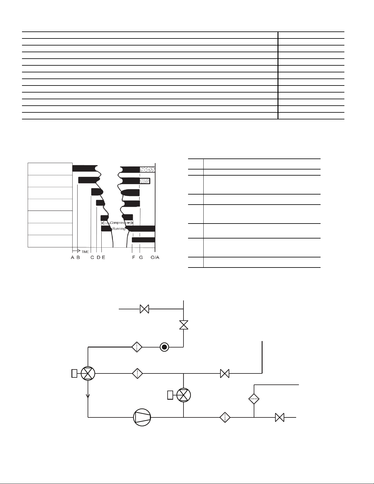
Table 2 — Prestart Checks
A
START INITIATED: prestart checks are made; evaporator
pump started.*
B Condenser water pump started (5 seconds after A).
C
Water flows verified (30 seconds to 5 minutes maximum
after B). Chilled water temperatures checked against control
point. Guide vanes checked for closure. Refrigerant pump
started; tower fan control enabled.
D
Ref pressure verified (15 seconds minimum, 300 seconds
maximum after C).
E
Compressor motor starts; compressor on-time and service
on-time start, 15-minute inhibit timer starts (10 seconds after
D), total compressor starts advances by one, and the number of starts over a 12-hour period advances by one.
F
SHUTDOWN INITIATED; Compressor motor stops; compressor on-time and service on-time stop, and 2-minute
inhibit timer starts.
G
Refrigerant pump and evaporator pumps de-energized
(120 seconds after F).Condenser pump and tower fan control may continue to operate if condenser pressure is high.
Evaporator pump may continue if in RECYCLE mode.
O/A
Restart permitted (both inhibit timers expired: minimum of
15 minutes after E; minimum of 2 minutes after F).
* Auto Restart After Power Failure Timing sequence will be faster.
MACHINE SAFETIES
EVAPORATOR PUMP
CONDENSER
WATER PUMP
WATER FLOW, CHILLED WATER
TEMP, GUIDE VANES, REF PUMP,
TOWER FAN CONTROL
REF PUMP
COMPRESSOR,
COMPRESSOR ONTIME,
SERVICE ONTIME
15-MINUTE
START-TO-STA RT
2-MINUTE
STOP-TO-START
PUMP
REFRIGERANT FILTER
PURGE DRAIN
COOLER
SIGHT GLASSSTRAINER
STRAINER
PUMPOUT
DRAIN
BEARING FILTER
BEARING
SUPPLY
HS FLOAT CHAMBER
2-WAY
ACTUATED VALVE
3-WAY
ACTUATED
VALV E
PRESTART CHECK CONDITION* STATE NUMBER
STARTS IN 12 HOURS 8 (not counting recycle restarts or auto restarts after power failure) Alert – 100
COND PRESSURE COND PRESS OVERRIDE – 20 psi Alert – 102
#RECYCLE RESTARTS LAST 4 HOURS > 5 Alert – 103
COMP BEARING TEMP >= COMP BEARING ALERT– 10°F (5.6°C) Alarm – 230
COMP MOTOR WINDING TEMP COMP MOTOR WINDING– 10°F (5.6°C) Alarm – 231
COMP DISCHARGE TEMPERATURE COMP DISCHARGE ALERT– 10°F (5.6°C) Alarm – 232
EVAP_SAT <Evap trip point** + EVAP OVERRIDE DELTA T Alarm – 233
EVAP REFRIG LIQUID TEMP <Evap trip point** + EVAP OVERRIDE DELTA T Alarm – 233
AVERAGE LINE VOLTAGE UNDERVOLTAGE THRESHOLD
AVERAGE LINE VOLTAGE OVERVOLTAGE THRESHOLD
CHECK FOR GUIDE VANE 1 CALIBRATION Alarm – 236
CHECK FOR GUIDE VANE 2 CALIBRATION Alarm – 238
* If Prestart Check Condition is True, then resulting State is as indi-
cated in the State Number column.
† See the Controls Operation and Troubleshooting guide for alarm
and alert codes.
††
††
Alarm – 234
Alarm – 235
** Evap trip point = 33°F (0.6°C) (water) or EVAP REFRIG TRIP-
POINT (brine).
†† Condition ignored for Eaton/Rockwell VFDs.
†
Fig. 12 — Control Timing Sequence for Normal Start-Up
Fig. 13 — Lube Assembly Schematic
14
Page 15

Shutdown
Unit Start/Stop
The unit can be stopped locally using the HMI by pressing the
green Start/Stop icon . The Unit Start/Stop screen is displayed. Press Confirm Stop (see Fig. 14).
Fig. 14 — Confirm Stop
Chiller shutdown begins if any of the following occurs:
• Local OFF button is pressed
• A recycle condition is present
• The time schedule has gone into unoccupied mode when in
Network or Local Schedule control mode
• The chiller protective limit has been reached and chiller is
in alarm
• The start/stop status (CHIL_S_S) is overridden to stop
from the network when in Network mode
If the chiller is normally shut down from running, soft stop shutdown will be performed. The soft stop feature closes the guide
vanes of the compressor automatically if a non-alarm stop signal
occurs before the compressor motor is de-energized.
Any time the compressor is directed to stop (except in the cases
of a fault shutdown), the guide vanes are directed to close and
VFD is directed to minimum speed for variable speed compressor, and the compressor shuts off when any of the following is true:
• PERCENT LOAD CURRENT (%) drops below the SOFT
STOP AMPS THRESHOLD
• ACTUAL GUIDE VANE OPENING drops below 4%
• 4 minutes have elapsed after initializing stop.
When any one of the above conditions is true, the shutdown sequence stops the compressor by deactivating the compressor
start relay. Then the guide vane shall be closed and stay at the
fully closed position, the refrigerant pump relay will be turned
off after 120 seconds post lube, and the chilled water/brine
pump and condenser water pump will be shut down.
BEFORE INITIAL START-UP
Job Data Required
• list of applicable design temperatures and pressures (product data submittal)
• chiller certified prints
• VFD details and wiring diagrams
• diagrams and instructions for special controls or options
• 19DV Installation Instructions
Equipment Required
• mechanic’s tools (refrigeration)
• digital volt-ohmmeter (DVM)
• true RMS (root mean square) digital multimeter with
clamp-on current probe or true RMS digital clamp-on ammeter rated for at least 480 vac
• electronic refrigerant leak detector
• absolute pressure manometer or electronic micron gage
(see Fig. 15)
• drum charging valve (unless refrigerant bottles already
have charging valves)
• charging hose
Fig. 15 — Digital Vacuum Gage
Remove Shipping Packaging
Remove any packaging material from the unit, VFD, and control
panels. Inspect the unit for damage that occurred during shipping
or installation. Document any damage that was identified.
Tighten All Gasketed Joints
Gaskets normally relax by the time the chiller arrives at the
jobsite. Tighten all gasketed joints to ensure a leak-tight chiller
(does not apply to refrigerant joints covered by factory insulation). Gasketed joints (excluding O-rings) may include joints at
some or all of the following:
• Waterbox covers
• Compressor first suction elbow flanges (at compressor and
at the evaporator)
• Compressor secondary suction flanges (at compressor and
low side float chamber)
• Compressor discharge flange
• Evaporator inlet line spacer (both sides)
• Envelope control flange (both sides of valve)
• ICP piping flange
• High and low side float chamber covers
See Tables 3 and 4 for bolt torque requirements.
Check Chiller Tightness
Figure 16 outlines the proper sequence and procedures for leak
testing.
The 19DV chillers are shipped without the refrigerant charge.
The chiller is shipped with a 15 psig (103 kPa) dry nitrogenholding charge.
If the 15 psig factory nitrogen charge is present, then release pressure and proceed to pull a deep vacuum on the unit. Vacuum
should be pulled through 1
tom of first stage side of the evaporator. Upon completion of pulling the required vacuum the chiller can be charged with refrigerant. The
1
/
-in. charging valve on top of the evaporator shell should
2
1
/
-in. female NPT located under bot-
2
15
Page 16

be used for charging by lifting charge cylinder and gravity feed
into the evaporator. The chiller should be charged with refrigerant.
If the holding charge is not present, the chiller must be examined
for leaks. To test for leaks add a small refrigerant holding charge to
unit and pressurize with nitrogen up to 20 psig to determine and
correct the origin of the leak. Use an electronic leak detector to
check all flanges and solder joints after the chiller is pressurized. If
the 15 psig factory nitrogen charge is present, then release pressure and proceed to pull a vacuum on the unit. The chiller should
Table 3 — Bolt Torque Requirements, Foot Pounds
be charged with refrigerant. Follow the leak test chiller procedure
(page 18).
If the chiller is spring isolated, keep all springs blocked in both
directions to prevent possible piping stress and damage during
the transfer of refrigerant from vessel to vessel during the leak
test process, or any time refrigerant is being transferred. Adjust
the springs when the refrigerant is in operating condition and
the water circuits are full. Any piping weights are to be separately supported.
SAE 8
HEX HEAD
SA354 GR BD
BOLT SIZE
(in.)
SAE 2, A307 GR A
HEX HEAD
NO MARKS
LOW CARBON STEEL
SOCKET HEAD OR HEX
WITH 3 RADIAL LINES, OR SA499
MEDIUM CARBON STEEL
SAE 5
WITH 6 RADIAL LINES OR
MEDIUM CARBON STEEL
MINIMUM MAXIMUM MINIMUM MAXIMUM MINIMUM MAXIMUM
1
/
4
5
/
16
3
/
8
7
/
16
1
/
2
9
/
16
5
/
8
3
/
4
7
/
8
46 69913
8 11 13 18 20 28
13 19 22 31 32 46
21 30 35 50 53 75
32 45 53 75 80115
46 65 75 110 115 165
65 95 105 150 160 225
105 150 175 250 260 370
140 200 265 380 415 590
1 210 300 410 580 625 893
1
/
1
8
1
1
/
4
3
1
/
8
1
/
1
2
5
1
/
8
3
1
/
4
7
/
1
8
330 475 545 7809851,410
460 660 770 1,100 1,3801,960
620 885 1,020 1,460 1,840 2,630
740 1060 1,220 1,750 2,200 3,150
1010 1450 1,670 2,390 3,020 4,310
1320 1890 2,180 3,110 3,930 5,610
1630 2340 2,930 4,190 5,2807,550
2 1900 2720 3,150 4,500 5,670 8,100
1
2
/
4
1
/
2
2
3
2
/
4
2180 3120 4,550 6,500 8,200 11,710
3070 4380 5,000 7,140 11,350 16,210
5120 7320 8,460 12,090 15,710 22,440
3 6620 9460 11,040 15,770 19,900 28,440
Table 4 — Bolt Torque Requirements, Foot Pounds (Metric Bolts)
BOLT SIZE
(METRIC)
MINIMUM MAXIMUM MINIMUM MAXIMUM
M4 1.75 2.5 2.5 3.5
M6 698 12
M8 14 20 20 30
M10 28 40 40 57
M12 48 70 70 100
M16 118 170 170 240
M20 230 330 330 470
M24 400 570 570 810
M27 58 0 830 820 1175
CLASS 8.8 CLASS 10.9
16
Page 17

19DV Field Procedure for new units with
less than 15 psig holding charge or units
suspected of leaking.
1. Attach compound gage to vessel
2. Note ambient temperature
Raise pressure to 20 psig (138 kPa)
using Nitrogen with added tracer gas for
electronic leak detection
Leak check
Pass
Evacuate vessel and
perform standing
vacuum test
Locate and mark all
leak sources
Dehydrate
Pass
Charge unit
NOTE: Be sure to add refrigerant
as gas until chiller pressure exceeds
15 in Hg (vac) / 380 mmHg (vac)
to avoid possible tube freezing.
Repair all leaks
No
Yes
Yes
No
Fig. 16 — 19DV Leak Test Procedures
17
Page 18

Refrigerant Tracer
Carrier recommends the use of an environmentally acceptable
refrigerant tracer for leak testing with an electronic refrigerant
detector.
Ultrasonic leak detectors can also be used if the chiller is under
pressure.
WARNING
Do not use air or oxygen as a means of pressurizing the
chiller. Mixtures of HFO R-1233zd(E) and air at elevated
pressure can undergo combustion, resulting in equipment
damage and possible personal injury.
Leak Test Chiller
Due to regulations regarding refrigerant emissions and the difficulties associated with separating contaminants from the refrigerant, Carrier recommends the following leak test procedure.
Refer to Table 5 for refrigerant pressure/temperature values.
1. If the pressure readings are normal for the chiller condition:
a. Evacuate the charge from the vessels, if present.
b. Raise the chiller pressure, if necessary, by adding
refrigerant until pressure is at the equivalent saturated
pressure for the surrounding temperature.
CAUTION
Never charge liquid refrigerant into the chiller if the pressure in the chiller is less than 15 in. Hg (vac) / 380 mm Hg
(vac) for HFO R-1233zd(E). Charge as a gas only, with the
evaporator and condenser pumps running, until this pressure is reached, using PUMPDOWN/LOCKOUT (located
in the Maintenance menu) and END LOCKOUT mode on
the PIC6 control interface. Flashing of liquid refrigerant at
low pressures can cause tube freeze-up and considerable
damage.
c. Leak test chiller as outlined in Steps 3 to 7.
2. If the pressure readings are abnormal for the chiller condition:
a. Prepare to leak test chiller.
b. For cooling machines, check for leaks by connecting a
nitrogen bottle with added tracer to allow for electronic leak detection if possible; otherwise, soap bubble solution is to be used. Raise the pressure to
20 psig (138 kPa). If electronic leak detector is avail-
able, ensure small amount of tracer material is added.
c. Plainly mark any leaks that are found.
d. Release the pressure in the system.
e. Repair all leaks.
f. Retest the joints that were repaired.
NOTE: Suggested test pressure is 20 psig (138 kPa); maximum allowable test pressure 45 psig (310 kPa).
3. Check the chiller carefully with an electronic leak detector
or soap bubble solution.
4. Leak Determination — If an electronic leak detector indicates a leak, use a soap bubble solution, if possible, to confirm. Total all leak rates for the entire chiller. Leakage at
rates greater than 0.1% of the total charge per year should
be repaired. Local regulation governs the requirements for
when repair of leaks become mandatory. Note the total
chiller leak rate as well as the full charge amount on the
start-up report.
5. If no leak is found during the initial start-up procedures,
complete the transfer of refrigerant gas from the storage
tank to the chiller. Recover any gas used for leak detection
purposes as required per local jurisdiction.
6. If no leak is found after a retest:
a. Perform a standing vacuum test as outlined in the
Standing Vacuum Test section, below.
b. If the chiller fails the standing vacuum test, repeat
leak test and repair.
c. If the chiller passes the standing vacuum test, dehy-
drate the chiller. Follow the procedure in the Chiller
Dehydration section, page 20. Charge the chiller with
refrigerant.
7. If the chiller is opened to the atmosphere for an extended
period, evacuate it before repeating the leak test. A nitrogen purge should be maintained to reduce the potential for
corrosion when open to the atmosphere.
NOTE: Alternate optional leak testing method is to isolate the water circuits and use a portable water heater to raise the temperature
of the evaporator and condenser water circuits to approximately
100°F (38°C) which corresponds to a pressure of approximately
14.40 psig (99.3 kPag).
Standing Vacuum Test
When performing the standing vacuum test or chiller dehydration, use a manometer or a wet bulb indicator. Dial gages cannot indicate the small amount of acceptable leakage during a
short period of time.
1. Attach an absolute pressure manometer or wet bulb indicator to the chiller.
2. Evacuate the vessel to at least 18 in. Hg vac (41 kPa [abs]),
using a vacuum pump or a pumpout unit.
3. Valve off the pump to hold the vacuum and record the
manometer or indicator reading.
a. If the leakage rate is less than 0.05 in. Hg (0.17 kPa
in 24 hours, the chiller is sufficiently tight.
b. If the leakage rate exceeds 0.05 in. Hg (0.17 kPa)
24 hours, re-pressurize the vessel and test for leaks.
4. Repair the leak, retest, and proceed with dehydration.
)
in
18
Page 19

Table 5 — HFO R-1233zd(E) Pressure and Temperature
TEMP. PRESSURE
F C PSIA PSIG IN HG KPAG KPA ABS MMHG (VAC) % VACUUM
20.0 –6.7
22.0 –5.6
24.0 –4.4
26.0 –3.3
28.0 –2.2
30.0 –1.1
32.0 0.0
34.0 1.1
36.0 2.2
38.0 3.3
40.0 4.4
42.0 5.6
44.0 6.7
46.0 7.8
48.0 8.9
50.0 10.0
52.0 11.1
54.0 12.2
56.0 13.3
58.0 14.4
60.0 15.6
62.0 16.7
64.0 17.8
66.0 18.9
68.0 20.0
70.0 21.1
72.0 22.2
74.0 23.3
76.0 24.4
78.0 25.6
80.0 26.7
82.0 27.8
84.0 28.9
86.0 30.0
88.0 31.1
90.0 32.2
92.0 33.3
94.0 34.4
96.0 35.6
98.0
100.0 37.8
102.0 38.9
104.0 40.0
106.0 41.1
108.0 42.2
110.0 43.3
112.0 44.4
114.0 45.6
116.0 46.7
118.0 47.8
120.0 48.9
122.0 50.0
124.0 51.1
126.0 52.2
128.0 53.3
130.0 54.4
36.7
5.16
5.43
5.72
6.01
6.32
6.64
6.98
7.33
7.69
8.06
8.45
8.86
9.28
9.72
10.17
10.64
11.13
11.63
12.15
12.69
13.25
13.83
14.43
15.05
15.69
16.34
17.03
17.73
18.46
19.20
19.98
20.77
21.59
22.44
23.31
24.21
25.13
26.08
27.06
28.07
29.10
30.17
31.26
32.39
33.54
34.73
35.95
37.20
38.48
39.80
41.16
42.54
43.97
45.42
46.92
48.45
–9.54
–9.27
–8.98
–8.69
–8.38
–8.06
–7.72
–7.37
–7.01
–6.64
–6.25
–5.8
–5.42
–4.98
–4.53
–4.06
–3.57
–3.07
–2.55
–2.01
–1.45
–0.87
–0.27
0.35
0.99
1.64
2.33
3.03
3.76
4.50
5.28
6.07
6.89
7.74
8.61
9.51
10.43
11.38
12.36
13.37
14.40
15.47
16.56
17.69
18.84
20.03
21.25
22.50
23.78
25.10
26.46
27.84
29.27
30.72
32.22
33.75
–19.4 –65.8 35.6 493.5 65
–18.9 –63.9 37.4 479.4 63
–18.3 –61.9 39.4 464.6 61
–17.7 –59.9 41.5 449.3 59
–17.1 –57.8 43.6 433.3 57
–16.4 –55.6 45.8 416.7 55
–15.7 –53.2 48.1 399.3 53
–15.0 –50.8 50.5 381.3 50
–14.3 –48.3 53.0 362.6 48
–13.5 –45.8 55.6 343.2 45
–12.7 –43.1 58.3 323.0 42
4
–11.9 –40.3 61.1 302.0 40
–11.0 –37.4 64.0 280.2 37
–10.1 –34.3 67.0 257.6 34
–9.2 –31.2 70.1 234.2 31
–8.3 –28.0 73.4 209.9 28
–7.3 –24.6 76.7 184.8 24
–6.2 –21.2 80.2 158.7 21
–5.2 –17.6 83.8 131.7 17
–4.1 –13.887.5 103.8 14
–2.9 –10.0 91.4 74.9 10
–1.8 –6.0 95.4 45.0 6
–0.6 –1.9 99.5 14.0 2
0.7 2.4 103.7 — —
2.0 6.8 108.1 — —
3.3 11.3 112.7 — —
4.7 16.0 117.4 — —
6.2 20.9 122.2 — —
7.6 25.9 127.2 — —
9.2 31.1 132.4 — —
10.7 36.4 137.7 — —
12.4 41.9 143.2 — —
14.0 47.5 148.9 — —
15.8 53.4 154.7 — —
17.5 59.4 160.7 — —
19.4 65.6 166.9 — —
21.2 71.9 173.3 — —
23.2 78.5 179.8 ——
25.2 85.2 186.6 — —
27.2 92.2 193.5 — —
29.3 99.3 200.7 — —
31.5 106.7 208.0 — —
33.7 114.2 215.5 — —
36.0 122.0 223.3 — —
38.4 129.9 231.3 — —
40.8 138.1 239.5 — —
43.3 146.5 247.9 — —
45.8 155.1 256.5 — —
48.4 164.0 265.3 — —
51.1 173.1 274.4 — —
53.9 182.4 283.8 ——
56.7 192.0 293.3 — —
59.6 201.8 303.1 — —
62.6 211.8 313.2 — —
65.6 222.1 323.5 — —
68.7 232.7 334.1 — —
19
Page 20

Check the Installation
Use the following instructions to verify the condition of the
installation. Note that the contractor should not apply power
to the chiller before the Carrier Start-up Technician arrives at
the job site.
1. Inspect the water piping to the chiller to confirm it is correct. Confirm it is adequately supported from the chiller
and there are isolation valves installed.
2. Turn off, lock out, and tag the input power to the drive.
3. Wait a minimum of 5 minutes for the DC bus to discharge.
4. All wiring should be installed in conformance with the
applicable local, national, and international codes (e.g.,
NEC/CSA).
5. Remove any debris, such as metal shavings, from the
enclosure.
6. Check that there is adequate clearance around the
machine.
7. Verify that the wiring to the terminal strip and the power
terminals is correct and that no external voltage potential
is connected to any of the inputs.
8. Verify that all of the VFD power module circuit board connectors are fully engaged and taped in place.
9. Check that the field-installed wire size is within terminal
specifications and that the wires are tightened properly and
adequately supported.
10. Check that specified branch circuit protection is installed
and correctly rated.
11. Check that the incoming power is within ±10% of chiller
nameplate voltage.
12. Verify that a properly sized ground wire is installed and a
suitable earth ground is used. Check for and eliminate any
grounds between the power leads. Verify that all ground
leads are unbroken to the power supply. Only a wye secondary power supply transformer with solidly grounded
neutral is acceptable as a power supply to this chiller. If a
ground wire is not present or the transformer secondary is
any other type than a wye with solidly grounded delta,
please contact the Technical Service Manager or Service
Engineering.
Inspect Wiring
WARNING
Do not check the voltage supply without proper equipment
and precautions. Serious personal injury may result. Follow
power company recommendations.
CAUTION
Do not apply any kind of test voltage, even for a rotation
check, if the chiller is under a dehydration vacuum. Insulation breakdown and serious damage may result.
WARNING
Do not apply power unless a qualified Carrier technician is
present. Serious personal injury may result.
1. Examine the wiring for conformance to the job wiring diagrams and all applicable electrical codes.
2. Ensure that the VFD is protected by fused disconnects or
circuit breakers as per electrical code.
3. Compare the ampere rating on the VFD nameplate to rating on the compressor nameplate.
4. Check that there is adequate service clearance around the
machine.
5. Check that specified branch circuit protection is installed
and correctly rated.
6. Ensure there is capability to turn off, lock out, and tag the
input power to the drive.
7. If power is applied to the drive then wait a minimum of
5 minutes for the DC bus to discharge and check DC bus
voltage prior to starting any work.
8. Inspect the control panels and VFD enclosure to ensure
that the contractor has used the knockouts or provided top
hat to feed the wires into the enclosures. Generally, wiring
into the top of the enclosures can allow debris to fall into
the enclosures. Clean and inspect the interior of the power
panel and VFD enclosure if this has occurred. If metal particulate has fallen into the rectifier or inverter assemblies
contact Service Engineering or your Technical Service
Manager for further instructions.
9. Check that the incoming power is within ±10% of chiller
nameplate voltage.
10. Check that the room environmental conditions match the
chiller enclosure type.
11. Ensure the customer’s contractor has verified proper operation of the pumps, cooling tower fans, and associated
auxiliary equipment. This includes ensuring motors are
properly lubricated and have proper electrical supply and
proper rotation. Carrier must maintain pump control for
freeze protection algorithm.
12. Verify that the incoming source does not exceed the SCCR
(short circuit current rating) of the equipment marking.
13. Ensure all electrical equipment and controls are properly
grounded in accordance with the job drawings, certified
drawings, and all applicable electrical codes.
CAUTION
Disconnect leads to VFD prior to megohm test. The voltage
generated from the tester can damage VFD components.
Test #1: For 3-lead motor, tie terminals 1, 2, and 3 together and
test between the group and ground.
1. With the tester connected to the motor leads, take 10-second
and 60-second megohm readings.
2. Divide the 60-second resistance reading by the 10-second
reading. The ratio, or polarization index, must be one or
higher. Both the 10 and 60-second readings must be at
least 50 megohms. If the readings on a field-installed
starter are unsatisfactory, repeat the test at the motor with
the power leads disconnected. Satisfactory readings in this
second test indicate the fault is in the power leads.
Test #2: Only perform this test if the unit has been disassembled at the job site, if the starter has been removed, or during
annual maintenance.
Perform a megohm test from each terminal to ground. The
megohm value should be greater than 20 megohm. Note that if
a megohm test is performed between the terminals it will show
a direct short and is not a valid test because of the 3 terminal
motor internal delta configuration.
Chiller Dehydration
Dehydration is recommended if the chiller has been open for a
considerable period of time, if the chiller is known to contain
moisture, or if there has been a complete loss of chiller holding
charge or refrigerant pressure.
20
Page 21

CAUTION
Do not start or megohm-test the compressor motor or any
other pump motor, even for a rotation check, if the chiller is
under dehydration vacuum. Insulation breakdown and severe damage may result.
WARNING
Power to the motor and VFD must be disconnected by an isolation switch before placing the machine under a vacuum. To
be safe, isolate input power before evacuating the chiller if you
are not sure if there are live leads to the hermetic motor.
Dehydration can be done at room temperatures. Using a cold
trap (Fig. 17) may substantially reduce the time required to complete the dehydration and is recommended should the unit be exposed to liquid moisture. The higher the room temperature, the
faster dehydration takes place. At low room temperatures, a very
deep vacuum is required to boil off any moisture and heating of
the water in the water circuits of the chiller to approximately
100°F (38°C) may be required.
pockets of moisture can turn into ice. The slow rate of evaporation (sublimation) of ice at these low temperatures and
pressures greatly increases dehydration time.
6. Valve off the vacuum pump, stop the pump, and record the
instrument reading.
7. After a 2-hour wait, take another instrument reading. If the
reading has not changed, dehydration is complete. If the
reading indicates vacuum loss, repeat Steps 4 and 5.
8. If the reading continues to change after several attempts,
perform a leak test (maximum 45 psig [310 kPa] pressure).
Locate and repair the leak, and repeat dehydration.
9. Once dehydration is complete, the evacuation process can
continue. The final vacuum prior to charging the unit with
refrigerant should in all cases be 29.9 in. Hg (500 microns,
0.07 kPa [abs]) or less.
Inspect Water Piping
Refer to piping diagrams provided in the certified drawings
and the piping instructions in the 19DV Installation Instructions manual. Inspect the piping to the evaporator and condenser. Be sure that the flow directions are correct and that all piping specifications have been met.
Piping systems must be properly vented with no stress on waterbox nozzles and covers. Water flows through the evaporator
and condenser must meet job requirements. Measure the pressure drop across the evaporator and the condenser.
Fig. 17 — Dehydration Cold Trap
Perform dehydration as follows:
1. Connect a high capacity vacuum pump (5 cfm [.002 m
or larger is recommended) to the refrigerant vacuum/
charging valve (Fig. 2). Tubing from the pump to the
chiller should be as short in length with a minimum diameter of 0.5 in. (13 mm) and as large in diameter as possible
to provide least resistance to gas flow.
2. Use an absolute pressure manometer or a electronic
micron gage to measure the vacuum. Open the shutoff
valve to the vacuum indicator only when taking a reading.
Leave the valve open for 3 minutes to allow the indicator
vacuum to equalize with the chiller vacuum.
3. If the entire chiller is to be dehydrated, open all isolation
valves (if present).
4. With the chiller ambient temperature at 60°F (15.6°C) or
higher, operate the vacuum pump until the manometer
reads 29.8 in. Hg (vac), –14.63 psig (–100.9 kPag), or a
vacuum indicator reads 35°F (1.7°C). Operate the pump
an additional 2 hours.
5. Do not apply a greater vacuum than 29.82 in. Hg vac
(757.4 mm Hg) or go below 33°F (0.56°C) on the wet bulb
vacuum indicator. At this temperature and pressure, isolated
3
/s]
CAUTION
Water must be within design limits, clean, and treated to ensure proper chiller performance and to reduce the potential of
tube damage due to corrosion, scaling, or erosion. Carrier assumes no responsibility for chiller damage resulting from untreated or improperly treated water.
Check Safety Valves
Be sure safety valves have been piped to the outdoors in compliance with the latest edition of ANSI/ASHRAE Standard 15
and applicable local safety codes. Piping connections must allow for access to the valve mechanism for periodic inspection
and leak testing.
The standard 19DV relief devices are set to relieve at 57 psig
(393 kPa) chiller design pressure. To avoid potential rupture
the chiller should never be pressurized above 45 psig (310 kPa)
for any testing purpose.
Check Purge Compressor Operation
Enter Quick Test menu (under Main Menu) and select “Quick
Test Purge Comp.” Connect a pressure gage to purge compressor inlet Schrader valve (suction is top fitting).
The purge system is shown in Fig. 18. The reading should be
about 0 ± 0.25 psig (–15.6 to –14.3°F) [0 ± 1.724 kPa (–26.5 to
–25.7°C)]. If not, adjust the purge expansion valve in the
R-134a purge compressor circuit until the reading is correct.
NOTE: This step should only be performed if the purge is not
working correctly. The installation of the gage will result in a loss
of refrigerant and the charge of R-134a is a very small quantity affecting the operation of the purge. The charge should be weighed
into this circuit using a charging cylinder or similar device.
21
Page 22

NOTE: CLOCKWISE ROTATION OF
EXPANSION VALVE ADJUSTMENT
SCREW INCREASES THE PRESSURE
SETTING AND COUNTERCLOCKWISE
ROTATION DECREASES PRESSURE
SETTING.
EXPANSION VALVE
Fig. 18 — Purge System
Ground Fault Troubleshooting
Follow this procedure only if ground faults are declared by the
chiller controls. Test the chiller compressor motor and its power lead insulation resistance with a 500-v insulation tester such
as a megohmmeter.
1. Open the VFD main disconnect switch and follow lockout/
tagout rules.
CAUTION
The motor leads must be disconnected from the VFD before an insulation test is performed. The voltage generated
from the tester can damage the VFD.
2. Perform test #1: For 3-lead motor, tie terminals 1, 2, and 3
together and test between the group and ground.
a. With the tester connected to the motor leads, take 10-
second and 60-second megohm readings.
b. Divide the 60-second resistance reading by the 10-
second reading. The ratio, or polarization index, must
be one or higher. Both the 10 and 60-second readings
must be at least 50 megohms. If the readings are
SUCTION
SCHRADER
VALVE
unsatisfactory, repeat the test at the motor with the
power leads disconnected. Satisfactory readings in
this second test indicate the fault is in the power leads.
3. Perform test #2: Only perform this test if the unit has been
disassembled at the job site, if the starter has been
removed, or during annual maintenance.
Perform a megohm test from each terminal to ground. The
megohm value should be greater than 20 megohm. Note
that if a megohm test is performed between the terminals it
will show a direct short and is not a valid test because of
the 3 terminal motor internal delta configuration.
Carrier Comfort Network® Interface
The Carrier Comfort Network (CCN) communication bus wiring is supplied and installed by the electrical contractor. It consists of shielded, 3-conductor cable with drain wire.
The system elements are connected to the communication bus
in a daisy chain arrangement. The positive pin of each system
element communication connector must be wired to the positive pins of the system element on either side of it. The negative pins must be wired to the negative pins. The signal ground
pins must be wired to the signal ground pins. See installation
manual.
22
Page 23

NOTE: Conductors and drain wire must be 20 AWG (American Wire Gage) minimum stranded, tinned copper. Individual
conductors must be insulated with PVC, PVC/nylon, vinyl,
1
, or polyethylene. An aluminum/polyester 100% foil
Tefl on
shield and an outer jacket of PVC, PVC/nylon, chrome vinyl,
or Teflon with a minimum operating temperature range of –4°F
to 140°F (–20°C to 60°C) is required. See Table 6 for cables
that meet the requirements.
Table 6 — Manufacturers and Cable Numbers
MANUFACTURER CABLE NO.
ALPHA 2413 or 5643
AMERICAN A22503
BELDEN 8772
COLUMBIA 02525
When connecting the CCN communication bus to a system element, a color code system for the entire network is recommended to simplify installation and checkout. The color code
shown in Table 7 is recommended.
Table 7 — Recommended Color Code
SIGNAL
TYPE
+ Red Red (+)
GROUND White White (G)
– Black Black (–)
CCN BUS CONDUCTOR
INSULATION COLOR
CCN TERMINAL
CONNECTION
WARNING
BE AWARE that certain automatic start arrangements can
engage the starter. Open the disconnect ahead of the starter
in addition to shutting off the chiller or pump. Failure to
follow this procedure may result in personal injury by electric shock.
WARNING
The main disconnect on the starter front panel may not deenergize all internal circuits. Open all internal and remote
disconnects before servicing the starter. Failure to follow this
procedure may result in personal injury by electric shock.
Inhibitor Charge
The inhibitor charge is included with the 19DV unit supplied
from the factory. No action associated with inhibitor is required
unless a new refrigerant charge is added or the inhibitor has
been distilled out of the existing refrigerant charge.
If the unit needs to be disassembled, add 1% (mass of total refrigerant charge) of inhibitor PP23BZ110001 (part number is for
1 Gal. Inhibitor Density is 8.2202 lb/Gal [0.985 Kg/L]). For example, see Tables 8 and 9; sum up the evaporator, condenser,
and economizer charge; take 1% of total charge; then calculate
required inhibitor volume. For a G20 evaporator with G22 condenser this yields: (700+413+342)lb*0.01/(8.2202 lb/Gal)=1.77
Gal (1 Gal + 99 oz) [6.70 L]. See Fig. 19 for field inhibitor addition assuming compressor running and negative evaporator pressure. A dose of Carrier inhibitor is supplied with the unit by the
factory.
Suggested Procedure:
1. Ensure availability of appropriate PPE such as protective
gloves/protective clothing/eye protection/face protection
and wash throughly after handling.
2. If new inhibitor charge is required, a refrigerant charge hose
can be used for this purpose or a hard pipe creating a funnel
using a 90 degree 2-in. x
1
/
-in. NPT female elbow reducer
2
along with a 2-in. NPT pipe to create a reservoir (add inhibitor as it is being sucked into the evaporator and close
1
/
-in.
2
charging ball valve prior to air being sucked into chiller).
Ensure that parts used to add inhibitor are clean to avoid any
chiller contamination.
Software Configuration
WARNING
Do not operate the chiller before the control configurations
have been checked and a Calibration and Control Test has
been satisfactorily completed. Protection by safety controls
cannot be assumed until all control configurations have
been confirmed.
See the 19DV with PIC6 Controls Operation and Troubleshooting manual for instructions on using the PIC6 interface to configure the 19DV unit. As the unit is configured, all configuration
settings should be written down. A log, such as the one shown
starting on page CL-1, provides a list for configuration values.
Charge Unit with Refrigerant
IMPORTANT: Turn on the chilled water and condenser water
pumps to prevent freezing.
.
CAUTION
Always operate the condenser and chilled water pumps
whenever charging, transferring, or removing refrigerant
from the chiller. Always confirm that water flow is established. Failure to follow this procedure may result in equipment damage.
CAUTION
The transfer, addition, or removal of refrigerant in spring
isolated chillers may place severe stress on external piping
if springs have not been blocked in both up and down directions. Failure to block springs in both up and down directions could result in severe personal injury and equipment
damage.
CAUTION
Always operate the condenser and chilled water pumps
during charging operations to prevent freeze-ups. Damage
could result to equipment if condenser and chilled water
pumps are not operated during pumpdown or charging.
WARNING
Always charge refrigerant gas into unit until pressure exceeds
water freeze temperature using PUMPDOWN/LOCKOUT
(located in the Maintenance menu) and TERMINATE LOCKOUT mode on the PIC6. Evaporator and condenser water
pumps must be running to prevent tube freezing.
For R-1233zd(E) water freeze point is exceeded at -15 in. Hg
(-51 kPa).
1. Teflon is a registered trademark of DuPont.
23
Page 24

All 19DV units are field charged. Charge the unit from refrigerant cylinders. Use Tables 8 and 9 to find expected approximate
charge by adding evaporator and condenser charge together. Refer to unit nameplate and E-Cat output for certified values.
Prior to charging ensure the following:
1. Standing vacuum test completed.
2. Only initiate refrigerant charging into a deep vacuum.
3. Adequate refrigerant supply is available as per unit nameplate.
CAUTION
Do not apply power to the VFD or motor when in a dehydration vacuum because it will result in equipment damage.
charging gas until the pressure is greater than the above saturation pressure temperature to avoid refrigerant flashing and potential tube freezing. Once required pressure is reached, switch
over to charge liquid either by lifting refrigerant cylinder above
charging valve to allow for gravity feed or, if charge is isolated
in storage tank, by using pumpout equipment suited for low
pressure refrigerant.
After the machine has been started, adjust charge for optimum
machine performance. Operate the chiller at design load and
then add or remove refrigerant slowly until the difference between the leaving chilled water temperature and the evaporator
refrigerant temperature reaches design conditions or becomes a
minimum. Do not overcharge.
Use the evaporator sight glass (see Fig. 20) to determine the
correct refrigerant at all times. During steady state operation at
full load, the boiling pool tubes under compressor suction
With water pumps running, connect charging hose from refrigerant cylinder to chiller evaporator charging valve. Start with
Table 8 — Refrigerant Charge — English (lbs)
G H
EVAPORATOR HXREFRIGERANT
G20 through
G2K
G40 through
G4K
— — G24, G29 402 H22, H27 763 H24, H29 507
WT [lbs]
700
840
CONDENSER
G22, G27, G2C,
G2H
G23, G28, G2D,
G2J
REFRIGERANT
WT [lbs]
413 H20, H25 741 H22, H27 484
405 H21, H26 752 H23, H28 495
should be covered with liquid refrigerant. There is no benefit to
a refrigerant liquid level higher than the tubes.
*
DV4
EVAPORATOR HXREFRIGERANT
WT [lbs]
CONDENSER
REFRIGERANT
WT [lbs]
— — G2E, G2K 397 H23, H28 778 H2C, H2H 431
——
——
— — G44, G49 455 H2B, H2G 707 H42, H47 563
— — G4E, G4K 448 H2C, H2H 716 H43, H48 576
————H2D, H2J726H44, H49590
————H2E, H2K736H4C, H4H499
————H40, H45841 H4D, H4J 508
————H41, H46853 H4E, H4K 518
————H42, H47866 — —
————H43, H48883— —
————H44, H49900——
————H4A, H4F795——
————H4B, H4G803 — —
————H4C, H4H813 — —
————H4D, H4J824 — —
————H4E, H4K836 — —
G42, G47, G4C,
G4H
G43, G48, G4D,
G4J
468 H24, H29 792 H2D, H2J 439
458 H2A, H2F 700 H2E, H2K 448
* The economizer factor for Frame G, H is 342 lbs, so for example the charge for
a G20 evaporator coupled with G22 condenser is:
700 lbs + 413 lbs + 342 lbs = 1455 lbs
24
Page 25

Table 9 — Refrigerant Charge — SI (kg)
Cooler
½" NPT charging valve
½" x 2" NPT reducer elbow or alternate adapter
2" NPT pipe
or alternate container
DV4
G H
EVAPORATOR HXREFRIGERANT
G20 through
G2K
G40 through
G4K
— — G24, G29 182 H22, H27 346 H24, H29 230
— — G2E, G2K 180 H23, H28 353 H2C, H2H 195
——
——
— — G44, G49 206 H2B, H2G 321 H42, H47 255
— — G4E, G4K 203 H2C, H2H 325 H43, H48 261
————H2D, H2J329H44, H49268
————H2E, H2K334H4C, H4H226
————H40, H45381H4D, H4J230
WT [kg]
318
381
CONDENSER
G22, G27, G2C,
G2H
G23, G28, G2D,
G2J
G42, G47, G4C,
G4H
G43, G48, G4D,
G4J
REFRIGERANT
WT [kg]
187 H20, H25 336 H22, H27 220
184 H21, H26 341 H23, H28 225
212 H24, H29 359 H2D, H2J 199
208 H2A, H2F 318 H2E, H2K 203
EVAPORATOR HXREFRIGERANT
*
WT [kg]
CONDENSER
REFRIGERANT
WT [kg]
————H41, H46387H4E, H4K235
————H42, H47393——
————H43, H48 401 — —
————H44, H49408 ——
————H4A, H4F361——
————H4B, H4G364——
————H4C, H4H369——
————H4D, H4J374——
————H4E, H4K379——
* The economizer factor for Frame G, H is 155 kg, so for example the charge for
a G20 evaporator coupled with G22 condenser is:
318 kg + 187 kg + 155 kg = 660 kg
Fig. 19 — Inhibitor Addition
25
Page 26

1
/2" NPT COOLER
CHARGING VALVE
Fig. 20 — Evaporator Charging Valve and Sight Glasses
HOME SCREEN
The home screen is the first screen shown after switching the
unit on. See Fig. 21. Note the Globe and Lock icons.
COOLER SIGHT GLASSES
(APPLY LIGHT TO ONE AND
VIEW THROUGH OTHER)
The Lock icon on the Home screen allows access to the password menu and displays current software version. See Fig. 23.
Fig. 21 — Home Screen
The Globe icon on the Home screen allows access to language and measurement settings. See Fig. 22.
Fig. 22 — Language and Units Selection Screen
Fig. 23 — Login Screen
CHANGE THE SET POINTS
To access the set point screen, press the lock icon on the Main
Menu. In the User Login menu, enter the password (default
USER password = 1111), and click accept. The screen will then
default back to the home screen. See Fig. 24. The Service Login
access is reserved for access to equipment service tables.
Fig. 24 — Home Screen
26
Page 27

The Main Menu screen is displayed. See Fig. 25. Press the Setpoint Table icon.
Fig. 25 — Main Menu
The Setpoint screen is displayed. See Fig. 26. Set the base demand limit, and either the LCW set point or the ECW set point.
To set a value, press the appropriate set point, enter the value,
and press OK. For more information, see the PIC6 Control
User Manual.
5. Equipment configuration
6. Automated control quick test
PA SS WO R D
The PIC6 provides a smart factory password for better security
and the password changes periodically. With a smart password,
only authorized users can log into the controller factory tables to
access key product configuration and maintenance data.
A password must be entered to access the Set Point or other
common user tables. See Fig. 28. User password can be
changed from the General Configuration Menu. USER CONFIGURATION allows change of the User access password.
IMPORTANT: Be sure to remember the password. Retain a
copy for future reference. Without the password, access will
not be possible unless accessed by a Carrier representative.
Factory password is required to enter configuration menus required for chiller setup.
Fig. 26 — Setpoint Menu
INPUT THE LOCAL OCCUPIED SCHEDULE
Access the schedule menu (Main Menu→Configuration
Menu→Schedule Menu) and set up the occupied time schedule
according to the customer’s requirements. If no schedule is
available, the default is factory set for 24 hours occupied, 7 days
per week including holidays. When the control mode is LOCAL
SCHEDULE, the chiller will be automatically started if the configured local schedule is occupied and will be automatically shut
down by the unoccupied schedule.
The Network Schedule should be configured if a CCN system
is being installed. When control mode is NETWORK, the
chiller can be started and stopped by the CHIL_S_S software
point as written by other equipment through the network command and network schedule. The Schedule Menu contains a table to set the Network Schedule if required.
For more information about setting time schedules, please refer
to the PIC6 Control User Manual.
INPUT SERVICE CONFIGURATIONS
See Fig. 27 for 19DV Configuration Tables. For specific values
for the following configurations, refer to the chiller performance data or job-specific data sheet:
1. Password
2. Log in/log out
3. Input time and date
4. Service parameters
Fig. 27 — 19DV Configuration Tables
Fig. 28 — User Login Screen
INPUT TIME AND DATE
Set day and time and, if applicable, holidays through MAIN
MENU SYSTEM CONFIGURATION and then select Date/
Time Configuration. See the Controls Operation and Troubleshooting guide for details. Because a schedule is integral to the
chiller control sequence, the chiller will not start until the time
and date have been set.
MODIFY CONTROLLER IDENTIFICATION IF NECESSARY
The CCN address can be changed from the Configuration
Menu. Change this address under CONTROL IDENTIFICATION for each chiller if there is more than one chiller at the
jobsite. Write the new address on the PIC6 Touch Screen module for future reference.
27
Page 28

CONFIGURE TABLES
Access the related tables through MAIN MENU CONFIGURATION MENU (Fig. 27) to modify or view job site parameters
Table 10 — Factory Parameters
DESCRIPTION RANGE UNITS DEFAULT VALUE
Factory Password
Chiller Type
19XR6/7=0,
19XR2~E/D/V=1,
19DV=2
Unit Type
Cool Only=0, Heat Mach=1
Comp (Single=0, Dual=1)
Chilled Medium Type
Water/Brine
Cond Shell Side MAWP
185PSI=0, 300PSI=1
19DV Comp Design Press
44PSI=0, 72PSI=1
Country Code
Free Cooling Option
VFD Option
No=0,FS VFD=1,Carrier=2,
Rockwell LF2=3, Eaton=4,
Rockwell STD=5
IOB3 Option (19XR2~E/D/V)
IOB4 Option
Guide Vane1 Type,
Digital=0, Analog=1
VFD Feedback Voltage Sel,
0-5V=0, 0-10V=1
Marine Option
Power Request Option
Cont. Power Request
Purge System Option
Liquid Bypass Option
Heat Reclaim Option
No=0, Full=1, Partial=2
0 to 65535 4444 n/a
0 to 2 0 2
0 to 1 0 Per selection
0 to 1 1 1
Water/Brine Water Per selection
0 to 1 1 n/a
0 to 1 0 1
0 to 999 8601
No/Yes No Per selection
0 to 5 0 2
0 to 1 0 n/a
No/Yes No Yes
0 to 1 0 1
0 to 1 0 n/a
0 to 1 0 n/a
0 to 1 0 n/a
0 to 1 0 n/a
Dsable/Enable Dsable Enable
Dsable/Enable Dsable Per selection
0 to 2 0 n/a
Table 11 — General VFD Config
Main Menu
Configuration MenuGeneral VFD Config [CFGGEVFD]
shown in 19DV Configuration tables. Tables 10-16 should be
verified or configured during startup/commissioning. Consult
chiller nameplates as indicated.
DESCRIPTION RANGE UNITS DEFAULT VALUE
VFD Gain 0.10 to 1.50 — 0.75 0.75
VFD Max Speed Per 90.0 to 110.0 % 100 100
VFD Min Speed Per 45.0 to 89.0 % 70 60
VFD Start Speed Per 65.0 to 100.0 % 100 100
VFD Current Limit 0.0 to 99999.0 AMPS 250 Nameplate
VFD Load Current 20mA 10.0 to 5000.0 AMPS 200 n/a
Comp Frequency 100% 45.0 to 62.0 Hz 50 Nameplate
VFD Load Current Input Enable/Dsable — Enable Dsable
Table 12 — 19DV Configuration
Main Menu
DESCRIPTION RANGE UNITS DEFAULT VALUE
Motor Pole Pair 1, 2 — 1 1
IGV2 Travel Limit 30 to 100% % 96 93.6
IGV2 minimum Degree 0 to 20 Degree 2 2
IGV2 Fully Open Degree 10 to 100 Degree 90 88
IGV2 Actuator Max Deg. 90 to 120 Degree 94 94
IGV2 Deg@IGV1 20 Deg 10 to 30 Degree 28.1 28.1
IGV2 Deg@IGV1 30 Deg 10 to 50 Degree 37.2 37.2
IGV2 Deg@IGV1 50 Deg 10 to 80 Degree 71.6 71.6
VFD Rate Speed Hz 10 to 200 Hz 8
Purge Regen Lasting Time 0 to 65535 minutes 120 120
Daily PG Pumpout Limit 20 to 200 minutes 50 50
Configuration Menu19DV Configuration [Table = CFG_19DV]
0.5 80.5
28
Page 29

Table 13 — UM VFD Config
Main Menu
DESCRIPTION RANGE UNITS DEFAULT VALUE
Compressor Speed 100% 47 to 110 Hz 50 Nameplate
Rated Line Voltage 200 to 13800 Volts 460 Nameplate
Motor Nameplate Current 10 to 1500 AMPS 200 Nameplate
Motor Rated Load Current 10 to 2000 AMPS 200 Nameplate
Motor Nameplate Voltage 200 to 13800 Volts 460 Nameplate
Motor Nameplate RPM 1500 to 3600 rpm 3000 Nameplate
Motor Nameplate KW 0 to 5600 KW 1500 Nameplate
Skip Frequency 1 0.0 to 102.0 Hz 30 30
Skip Frequency 2 0.0 to 102.0 Hz 30 30
Skip Frequency 3 0.0 to 102.0 Hz 30 30
Skip Frequency Band 0.0 to 102.0 Hz 0 0
Increase Ramp Time 5 to 60 sec 30 30
Decrease Ramp Time 5 to 60 sec 30 30
Line Voltage Imbalance% 1 to 10 % 10 10
Line Volt Imbalance Time 1 to 10 sec 10 10
Line Current Imbalance% 5 to 40 % 40 40
Line Current Imbal Time 1 to 10 sec 10 10
Motor Current Imbalance% 5 to 40 % 40 40
Motor Current Imbal Time 1 to 10 sec 10 10
Single Cycle Dropout Dsable/Enable — Dsable Dsable
PWM Switch Frequency
0=2 KHZ, 1=4 KHZ
Restore Defaults No/Yes — No No
LEN Comm Timeout 0 to 255 sec 10 10
Modbus Comm Timeout 0 to 255 sec 2 2
Gateway Modbus Baud Rate
4800=1, 9600=2, 19200=3, 38400=4
Configuration MenuUM VFD Configuration [CFGUMVFD]
0 to 1 — 0 1
1 to 4 — 2 2
Table 14 — Surge Correction Config
DESCRIPTION MENU NAME RANGE UNITS DEFAULT VALUE
Surge Line Configuration
PR = 0, Delta T = 1
IGV1 Pos Configuration
Degree =0, Percentage =1
Surge Delta Tsmax dts_max 0.0 to 150.0 ^F 70 Nameplate
Surge Delta Tsmin dts_min 0.0 to 150.0 ^F 45 Nameplate
PR at Full Load Opening pr_ful 1.0000 to 5.0000 — 3 3
PR at Minimum Opening pr_min 1.0000 to 5.0000 — 1.5 1.5
IGV1 Full Load Open Deg gv1_dful 80 to 120.0 — 88 88
Sound Ctrl IGV1 Open Deg gv1_dmed 10.0 to 40.0 — 27 27
IGV1 Minimum Open Deg gv1_dmin 0.0 to 10.0 — 2 2
IGV1 Maximum Open Deg gv1_dmax 90 to 120.0 — 109 94
IGV1 Minimum Position gv1_pmin 0.0 to 100.0 % 5 5
IGV1 Full Load Position gv1_pful 0.0 to 100.0 % 100 93.6
Envelop Line Offset sgl_off 1.0 to 3.0 ^F 2 1
Envelop Lower Deadband sgl_loff 0.5 to 3.0 ^F 1.5 1.5
Envelop Upper Deadband sgl_hoff 0.1 to 3.0 ^F 1.5 1.5
Surge Line Shape Factor sgl_shfh –1.000 to 0.000 — –0.01 Nameplate
Sound Line Shape Factor sgl_shfl 0.000 to 1.000 — 0.01 Nameplate
Envelop Speed Factor sgl_spdf 0.00 to 3.00 — 2 Nameplate
Surge Delay Time surg_del 0 to 120 sec 15 15
Surge Time Period surge_t 7 to 10 min 8 8
Surge Delta Amps % surge_a 5.0 to 40.0 % 20 20
GV1 Close Step Surge gvstp_sg 1.0 to 3.0 % 2 2
VFD Speed Step Surge
EC Valve Step Surge hgbpstsg 1.0 to 10.0 % 4 4
Surge Profile Offset sgl_pro 0.00 to 5.0 ^F 0 0
High Efficiency Mode high_eff Dsable/Enable — Enable Enable
High Noise Alert noi_alt Dsable/Enable — Enable Enable
sgl_cfg 0 to 1 — 0 1
gv1c_sel 0 to 1 — 0 0
vfdstpsg 1.0 to 5.0 % 1.5 1.5
29
Page 30

]
Table 15 — Option Configuration
Main Menu
DESCRIPTION RANGE UNITS DEFAULT VALUE
Auto Restart Option
Common Sensor Option
EC Valve Option
No=0, Cont.=1,ON/OFF=2, mA=3
EC Selection
Disable=0, Surge=1, Low Load=2,
Comb=3
ECV Open IGV1 Position
ECV Close IGV1 Position
ECV Off DT for Low Load
ECV On DT for Low Load
ECV Low Load DB
Head Pres Valve Option
Head Pres Delta P 0%
Head Pres Delta P 100%
Head Pressure Min Output
Tower Fan High Setpoint
Refrig Leakage Option
Refrig Leakage Alarm mA
Oil EXV Option
Oil Temp High Threshold
Oil Temp Low Threshold
Gas Torque Factor
Guide Vane/SRD Factor
Power Recovery Timeout
Condenser Flush Alert
Customer Alert Option
Ice Build Option
Ice Build Recycle
Ice Build Termin Source
Temp=0,Contact=1,Both=2
Water Pressure Option
No=0, Pres.=1, Pres.D=2
Water Flow Measurement
No=0, Flow Meter=1,Water Pres. D=2
Water Flow Determination
Sat Temp=0,Flow Switch=1
Water Flow at 4mA
Water Flow at 20mA
Evap Flow Rate Baseline
Evap Pres Drop Baseline
Cond Flow Rate Baseline
Cond Pres Drop Baseline
Water Pres Drop @20mA
Max Oil Pressure Diff
Oil Pump VFD Max Step
Vapor Source SV Delay
Vapor Source SV Option
Liquid Bypass Selection
Purge On Idle Option
Evap Liquid Temp Opt
Evap App Calc Selection
Sat Temp=0, Ref Temp=1
Configuration Menu Option Configuration [CONF_OPT
Dsable/Enable — Dsable Jobsite specific
Dsable/Enable — Dsable Jobsite specific
0 to 3 — 0 2 (if selected)
0 to 3 — 0 Jobsite specific
0.5 to 10.0 % 5 5 (adjust as required)
1.5 to 20.0 % 10 10 (adjust as required)
0.5 to 10 ^F 4 4 (adjust as required)
0.5 to 10 ^F 2 2 (adjust as required)
0.5 to 2.0 ^F 1 1 (adjust as required)
Dsable/Enable — Dsable Jobsite specific
20 to 85 PSI 25 25 (adjust as required)
20 to 85 PSI 50 50 (adjust as required)
0 to 100 % 0 0 (adjust as required)
55 to 105 °F 75 75 (adjust as required)
Dsable/Enable — Dsable Jobsite specific
4 to 20 mA 20 20 (adjust as required)
Dsable/Enable — Dsable Dsable
100 to 140 °F 122 n/a
90 to 130 °F 113 n/a
0.25 to 3.00 — 1 1
0.70 to 1.20 — 0.95 0.95
0 to 60 min 15 15
Dsable/Enable — Dsable Dsable
Dsable/Enable — Dsable Jobsite specific
Dsable/Enable — Dsable Jobsite specific
Dsable/Enable — Dsable Jobsite specific
0 to 2 — 0 Jobsite specific
0 to 2 — 0 Jobsite specific
0 to 2 — 0 Jobsite specific
0 to 1 — 0 Jobsite specific
0 to 200 GPS 0 (adjust as required)
0 to 200 GPS 0 (adjust as required)
0 to 150 GPS 0 (adjust as required)
0 to 20 PSI 0 (adjust as required)
0 to 150 GPS 0 (adjust as required)
0 to 20 PSI 0 (adjust as required)
10 to 40 PSI 10 (adjust as required)
35 to 60 PSI 50 n/a
0 to 10 % 7 n/a
0 to 10 min 5 n.a
Dsable/Engale — Dsable n.a
Dsable/Enable — Dsable Per selection
Dsable/Enable — Dsable (adjust as required for force)
Dsable/Enable — Enable n/a
0 to 1 — 1 1
30
Page 31

Table 16 — Service Parameters Table
Configuration MenuService Parameters [SERVICE]
Menu
DESCRIPTION Menu name RANGE DEFAULT UNITS VALUE*
Service Password ser_pass 0 to 65535 2222 —
Atmospheric Pressure atom_pre 8 to 15 14.5 PSI
GV1 Travel Limit gv1_lim 30 to 100 80.7 %
GV1 Closure at Startup gv1stpos 0 to 40 4 %
Controlled Fluid DB ctrl_db 0.5 to 2 1 ^F
Derivative EWT Gain ewtdgain 1 to 3 2 —
Proportional Dec Band gv1decdb 2 to 10 6 —
Proportional Inc Band gv1incdb 2 to 10 6.5 —
Maximum GV Movement max_gv 1.0 to 4.0 2 %
Demand Limit At 20 mA dem_20ma 10 to 100 40 %
Demand Limit Prop Band dem_pdb 3 to 15 10 %
Amps or KW Ramp per Min ldramprt 5 to 20 5 %
Temp Ramp per Min tmramprt 1 to 10 3 ^F
Recycle Shutdown Delta T rcysh_dt 0.5 to 4 1 ^F
Recycle Restart Delta T rcyst_dt 2 to 10 5 ^F
Damper Valve Act Delay dmp_dly 1 to 5 2 min
Damper Valve Close DB dmp_cldb 2 to 10 5 PSI
Damper Valve Open DB dmp_opdb 10 to 20 13 PSI
Damper Action Delta T dmp_dt 4 to 10 7 ^F
Lub Press Verify Time oilpvr_t 15 to 300 40 sec
Soft Stop Amps Threshold sf_st_th 40 to 100 70 %
Water Flow Verify Time wflow_t 0.5 to 5 5 min
Power Calibration Factor mbb_pfcl 0.5 to 2 1 —
Enable Excessive Starts ex_start No/Yes No —
Purge Active Temp SP pgt_set 30 to 90 65 —
Oil Stir Cycle(19XR6/7)
No Stir=0, 30s/30m=1,
1m/4h=2, Comb. 0&1=3
* Most Service Parameters do not require any change from default.
Adjust as required.
oilstiro 0 to 3 1 —
Field Set Up and Verification
IMPORTANT: Some parameters are specific to the chiller
configuration and will need to be verified prior to operation.
All command functions must be initiated from the HMI.
Use the HMI touch screen to confirm that the VFD values
match the chiller parameter labels and Chiller Builder design
data sheet. The VFD values can be located from Main Menu
Configuration Menu.
LABEL LOCATIONS
Verify the following labels have been installed properly and
match the chiller requisition:
• Surge Parameters — Located inside the HMI chiller control panel.
• Chiller identification nameplate — Located on the left side
of the control panel. See Fig. 29.
• VFD Nameplate data - located on the right side of the VFD.
See Fig. 29.
MODIFY EQUIPMENT CONFIGURATION IF NECESSARY
The EQUIPMENT SERVICE table has screens to select, view,
or modify parameters. Carrier’s certified drawings have the
configuration values required for the jobsite. Modify these values only if requested. Modifications can include:
• Chilled water reset
• Entering chilled water control (Enable/Disable)
• 4 to 20 mA demand limit
• Auto restart option (Enable/Disable)
• Remote contact option (Enable/Disable)
See the 19DV with PIC6 Controls Operation and Troubleshooting guide for more details about these functions; see the
Control Panel Schematic for field wiring.
Fig. 29 — Machine Identification Nameplate and VFD
Electrical Nameplate
31
Page 32

Perform a Controls Test (Quick Calibration/Quick Test)
NOTE: The QUICK TEST screens can only be accessed when the
chiller is in STOP mode.
Check the safety controls status by performing an automated
controls test. First, perform a Quick Calibration Test (Path
Main Menu → Quick Calibration). This is required for all
modulating analog actuators. Upon successful calibration, use
Quick Test (Main Menu → Quick Test) to verify operation on
desired components. Note that this is a very useful feature for
troubleshooting. On the QUICK TEST table screen, select a
test to be performed.
The Quick Test checks all outputs and inputs for proper functionality. In order to successfully proceed with the controls test,
the compressor must be off with no alarms showing, and voltage should be within ±10% of rating plate value. Each test asks
the operator to confirm the operation is occurring and whether
or not to continue. If an error occurs, the operator can try to address the problem as the test is being done or note the problem
and proceed to the next test.
NOTE: The refrigerant pump test will not energize the pump if
evaporator pressure is below –13 psig (–90 kPa).
When the controls test is finished the test stops and the QUICK
TEST menu displays. If a specific automated test procedure is
not completed, access the particular control test to test the
function when ready. Disable the Quick Test feature when testing is complete. For information about calibration, see the sections Checking Pressure Transducers, page 50, and High Altitude Locations, page 51.
EVAPORATOR AND CONDENSER PRESSURE TRANSDUCER AND WATERSIDE FLOW DEVICE CALIBRATION
(Waterside Device Optional with IOB Inputs Available)
Calibration can be checked by comparing the pressure readings
from the transducer to an accurate refrigeration gage reading.
The transducer can be checked and calibrated at 2 pressure
points. These calibration points are 0 psig (0 kPa) and between
10 psig (68.9 kPa) and 30 psig (206.8 kPa). To calibrate these
transducers:
1. Shut down the compressor and the evaporator and condenser pumps.
NOTE: There should be no flow through the heat exchangers.
2. Disconnect the transducer in question from its Schrader
fitting for evaporator or condenser transducer calibration.
For pump pressure or bearing pressure or flow device calibration keep transducer in place.
NOTE: If the evaporator or condenser vessels are at 0 psig (0 kPa)
atmospheric pressure, the transducers can be calibrated for zero
without removing the transducer from the vessel.
3. Access the PRESSURE screen from the Main Menu and
view the particular transducer reading (the evaporator
pressure, condenser pressure, economizer pressure, pump
inlet pressure, pump outlet pressure, bearing inlet pressure, bearing outlet pressure).
4. To calibrate a device, view the particular reading on the
screen. It should read 0 kPa. If the reading is not 0 kPa, but
within 35 kPa, the value may be set to zero while the
appropriate transducer parameter is highlighted. The value
will now go to zero. No high end calibration is necessary
for REF PUMP DELTA P or flow devices. If the transducer value is not within the calibration range, the transducer will return to the original reading. If the pressure is
within the allowed range (noted above), check the voltage
ratio of the transducer. To obtain the voltage ratio, divide
the voltage (dc) input from the transducer by the supply
voltage signal (see Maintenance Others in Maintenance
Menu) or measure across the positive (+ red) and negative
(– black) leads of the transducer. The voltage ratio must be
between 0.80 and 0.11 for the software to allow calibration. Rotate the waterside flow pressure device from the
inlet nozzle to the outlet nozzle and repeat this step. If
rotating the waterside flow device does not allow calibration then pressurize the transducer until the ratio is within
range. Then attempt calibration again.
5. A high pressure point can be calibrated between 10 and
30 psig (68.9 and 206.8 kPa) by attaching a regulated pressure source (usually from a nitrogen cylinder with high
resolution pressure gage). The high pressure point can be
calibrated by accessing the appropriate transducer parameter on the PRESSURES screen, highlighting the parameter, then increasing or decreasing the value to the exact
pressure on the refrigerant gage.
Pressures at high altitude locations must be compensated for,
so the chiller temperature/pressure relationship is correct. This
is set in the Service Parameters (Configuration Menu).
The PIC6 does not allow calibration if the transducer is too far
out of calibration. In this case, a new transducer must be installed and re-calibrated.
IMPORTANT: When screen display calibration is complete,
do not press Calibration Enable/Dsable since the new values
will be deleted. Values are kept by exiting the pressure sensor
table.
OPTIONAL THERMAL DISPERSION FLOW SWITCH CALIBRATION
Set the flow through the water circuit to the minimum safe
flow that will be encountered.
Reduce the sensitivity of the switch by turning the adjustment
counter-clockwise until the yellow LED turns off. This indicates that the switch is now open.
Increase the sensitivity of the flow switch by turning the adjustment potentiometer clockwise until the yellow LED is lit.
In case of nuisance trips at low flow, increase the sensitivity of
the switch by turning the potentiometer clockwise.
HYDRAULIC STATUS
The HYDRAULIC STATUS screen (access from the Main
Menu) provides a convenient way to detect if any of the evaporator/condenser pressure switches (if installed) are in need of
calibration. See Fig. 30 for the hydraulic status menu. With no
flow the water delta should read 0 kPa. If it does not, the value
may be set to zero using PRESSURE SENSOR CALIB located
in the Maintenance Menu. See Fig. 31 for the pressure sensor
calibration menu. High end calibration is not necessary.
Fig. 30 — Hydraulic Status Menu
32
Page 33

IMPORTANT: When screen display calibration is complete, do
not press Calibration Enable/Dsable since the new values will
be deleted. Values are kept by exiting the pressure sensor table.
Fig. 31 — Pressure Sensor Calibration Menu
INITIAL START-UP
Preparation
Before starting the chiller, verify:
1. Power is on to the VFD, chiller control panel, water
pumps, and other equipment as required.
2. Cooling tower water is at proper level and at-or-below
design entering temperature.
3. Chiller is charged with refrigerant and all refrigerant
valves are in their proper operating positions.
4. Valves in the evaporator and condenser water circuits are
open and flow is as per design.
NOTE: If the pumps are not automatic, ensure water is circulating
properly.
b. Open evaporator control valve, open condenser drain
valve, close condenser control valve, and close evapora-
tor control valve. Run refrigerant pump for 30 seconds.
c. Start the motor and ramp to 5 Hz in 10 seconds.
d. Once the motor speed reaches 5 Hz, stop motor.
e. Stop refrigerant pump 1 minute after motor speed
reaches 5 Hz, then reset all 4 refrigerant lubrication
valves to close.
f. Three minutes after motor speed reaches 5 Hz, close
first IGV. Status can be followed in Quick Test as
Check State IDLE=0, PreLub=1, Rotat=2, PosLub=3,
End=4.
6. When the VFD is energized and the motor begins to turn,
check for clockwise motor rotation through first stage
sight glasses. See Fig. 32.
IMPORTANT: Do not check motor rotation during coastdown. Rotation may have reversed during equalization of
vessel pressures.
CORRECT MOTOR ROTATION
IS CLOCKWISE WHEN VIEWED
THROUGH SUCTION PIPE
LEADING TO COMPRESSOR
1ST STAGE SIGHT GLASS
CAUTION
Do not permit water or brine that is warmer than 150°F
(65°C) to flow through the evaporator or condenser. Refrigerant overpressure may discharge through the relief device
and result in the loss of refrigerant charge (applicable only
with standard Charlotte rupture disk).
5. Access the PUMPDOWN/LOCKOUT feature from the
Maintenance Menu. Press the End Lockout button on the
touch screen and accept the “press OK to Terminate Lockout?” prompt. The unit is reset to operating mode. The chiller
is locked out at the factory to prevent accidental start-up.
Check Motor Rotation
1. Close the starter enclosure door.
2. Apply 3-phase power to drive.
3. The VFD checks for proper phase rotation as soon as power
is applied to the starter and the PIC6 controls power up.
4. An alarm message will appear on the HMI screen if the
phase rotation is incorrect. If this occurs reverse any 2 of
the 3 incoming power leads to the starter and reapply
power. The motor is now ready for a rotation check.
5. Go to Main Menu, Quick Test and Enable Quick Test following by enabling Motor Rotation Check. This starts the
following sequence:
a. Fully open the first IGV (inlet guide vane).
Fig. 32 — Correct Motor Rotation
Check Refrigerant Lube
1. In Quick Test the refrigerant lube pressure can be checked.
Open evaporator control valve, then run the refrigerant pump.
Pressure drop across the refrigerant pump must exceed 8 psig
(55 kPa). If pressure drop is negative, check the pump rotation. If pressure drop is below 8 psig (55 kPa), check for
clogged filter drier or bearing supply filter.
2. Press the Stop button and listen for any unusual sounds
from the compressor as it coasts to a stop.
To Prevent Accidental Start-Up
A chiller STOP override setting may be entered to prevent accidental start-up during service or whenever necessary. From
the Main Menu, access the General Parameters Menu and use
the down arrow to reach Stop Override on the GENUNIT table.
Change Stop Override to Yes; then execute the command by
touching the lightning button. The message “ALM-276 Protective Limit - Stop Override” will appear in the Home Screen
message area. To restart the chiller, access the same screen and
change the Stop Override option to No.
Check Chiller Operating Condition
Check to be sure that chiller temperatures, pressures, water
flows, and refrigerant levels indicate the system is functioning
properly.
33
Page 34

Instruct the Customer Operator(s)
Ensure the operator understands all operating and maintenance
procedures. Point out the various chiller parts and explain their
function as part of the complete system.
EVAPORATOR-CONDENSER
High side float chamber, relief devices, refrigerant charging valve,
temperature sensor locations, pressure transducer locations,
Schrader fittings, waterboxes and tubes, and vents and drains.
MOTOR COMPRESSOR ASSEMBLY
Guide vane actuator, transmission, motor cooling system, temperature and pressure sensors, sight glasses, motor temperature
sensors, and compressor serviceability.
COMPRESSOR LUBRICATION SYSTEM
Valves, dryers and filters, liquid level switch and inhibitor reclaim system.
ECONOMIZER
Float valve, drain valve, Schrader fitting, damper valve.
CONTROL SYSTEM
CCN and LOCAL start, reset, menu, softkey functions, HMI
operation, occupancy schedule, set points, safety controls, and
auxiliary and optional controls.
PURGE
Check for potential leaks by monitoring purge hours in RUNTIME. Note changes over time.
AUXILIARY EQUIPMENT
Starters and disconnects, separate electrical sources, pumps,
and cooling tower.
DESCRIBE CHILLER CYCLES
Refrigerant, motor cooling, lubrication, and liquid reclaim.
REVIEW MAINTENANCE
Scheduled, routine, and extended shutdowns, importance of a
log sheet, importance of water treatment and tube cleaning, and
importance of maintaining a leak-free chiller.
SAFETY DEVICES AND PROCEDURES
Electrical disconnects, relief device inspection, and handling
refrigerant.
CHECK OPERATOR KNOWLEDGE
Start, stop, and shutdown procedures, safety and operating controls, refrigerant charging, and job safety.
REVIEW THE START-UP, OPERATION, AND MAINTENANCE MANUAL.
FINE TUNING VPF (VARIABLE PRIMARY FLOW) SURGE PREVENTION
Figures 33-36 show how the parameters defined below will affect the configured surge line. The menu can be found under
Main Menu
Config.
NOTE: Before tuning surge prevention, check for VFD (variable
frequency drive) speed limitation or capacity overrides. If the
Configuration Menu Surge Correction
source of low capacity is found in one of these places, do not proceed with an attempt to tune the Surge Prevention configurations.
If capacity is not reached
and
1. ACTUAL GUIDE VANE POSITION < GUIDE VANE
TRAVEL RANGE
and
2. SURGE PREVENTION ACTIVE = YES (can be identified
in Main Menu
and
3. PERCENT LINE CURRENT < 100%
then the surge line is probably too conservative.
Note the following parameters from HMI when maximum
ACTUAL LINE CURRENT is achieved:
• EVAPORATOR REFRIGERANT TEMP
• EVAPORATOR PRESSURE
• CONDENSER REFRIG TEMP
• CONDENSER PRESSURE
• ACTUAL GUIDE VANE POSITION
• ACTUAL LINE CURRENT
The ACTIVE DELTA TSAT and the CALC REF DELTA
TSAT can be monitored on the Maintenance Menu
Correction screen. When ACTUAL DELTA TSAT exceeds
CALC REF DELTA TSAT + ENVELOPE LINE OFFSET
surge prevention will occur.
If ACTUAL GUIDE VANE POSITION is less than 30%, then
increase SURGE DELTA TSMIN in steps of 2ºF (1.2ºC) until
one of the three conditions listed above no longer applies. Do
not change SURGE DELTA TSMAX.
If ACTUAL GUIDE VANE POSITION is greater than 60%,
then increase SURGE DELTA TSMAX in steps of 2ºF (1.2ºC)
until cooling capacity is reached or one of conditions listed
above no longer applies. Do not change SURGE/HGBP DELTA
TSMIN.
If ACTUAL GUIDE VANE POSITION is more than 30%
AND less than 60%, then:
1. Increase SURGE DELTA TSMIN in steps of 2ºF (1.2ºC).
2. Increase SURGE DELTA TSMAX in steps of 2ºF (1.2ºC).
3. Repeat Steps 1 and 2 until one of the conditions listed
above no longer applies.
NOTE: DELTA TSMIN should seldom need to be increased more
than 10 degrees above the selection program value. Likewise,
DELTA TSMAX rarely requires more than a 2ºF (1.2ºC) increase.
If surge is encountered then the controls surge prevention algorithm surge line is probably too optimistic or high. Note following parameters from HMI at surge:
• EVAPORATOR REFRIGERANT TEMP
• EVAPORATOR PRESSURE
• CONDENSER REFRIG TEMP
• CONDENSER PRESSURE
• ACTUAL GUIDE VANE POSITION
• AVERAGE LINE CURRENT
Maintenance Menu Surge Correction)
Surge
34
Page 35

Fig. 33 — Effect of SURGE DELTA TSMIN on Surge
0
5
10
15
20
25
30
35
40
0 10 20 30 40 50 60 70 80 90 100 110
Tsmin= 30
Tsmin= 40
Tsmin= 50
GV_POS
Delta Tsat
0
5
10
15
20
25
30
35
40
45
0 102030405060708090100110
Tsmax= 60
Tsmax= 70
Tsmax= 80
GV_POS
Delta Tsat
0.00
5.00
10.00
15.00
20.00
25.00
30.00
35.00
40.00
45.00
50.00
55.00
60.00
0 102030405060708090100110
Shape factor
= -0.020
Shape factor
= -0.040
Shape factor
= -0.050
GV_POS
Delta Tsat
0
5
10
15
20
25
30
35
40
0 102030405060708090100110
Speed Factor
=1.60
Speed Factor
=1.85
Speed Factor
=2.00
GV_POS
Delta Tsat
Prevention
Fig. 34 — Effect of SURGE DELTA TSMAX on Surge
Prevention
Fig. 35 — Effect of SURGE LINE SHAPE FACTOR on
Surge Prevention
Fig. 36 — Effect of SURGE LINE SPEED FACTOR on
Surge Prevention
If ACTUAL GUIDE VANE POSITION is less than 30%, go to
Step 1. If ACTUAL GUIDE VANE POSITION is greater than
60%, then go to Step 3.
1. Do not change SURGE LINE SHAPE FACTOR from the
value selected by Chiller Builder (ECAT). Decrease SURGE
DELTA TSMIN in 1°F steps up to 5 times. Monitor chiller
for surge.
2. If ACTUAL GUIDE VANE POSITION is still less than
30% and Step 1 failed, increase the value of SURGE LINE
SHAPE FACTOR in steps of 0.01 up to 2 times. For example, if surge is encountered when shape factor is –0.06,
increase the SURGE LINE SHAPE FACTOR to –0.05. If
this does not solve the problem, go to Step 5, even if
ACTUAL GUIDE VANE POSITION is less than 30%.
3. Do not change SURGE LINE SHAPE FACTOR from the
value selected by Chiller Builder (ECAT). Decrease SURGE
DELTA TSMAX by 1°F steps up to 5 times. Monitor chiller
for surge.
4. If ACTUAL GUIDE VANE POSITION is greater than
60% and Step 3 failed to eliminate surge, then set SURGE
DELTA TSMAX to 5°F below the value specified by
Chiller Builder (ECAT). Increase the value of the SURGE
LINE SHAPE FACTOR in steps of 0.01 up to 2 times. For
example, if surge is encountered when the SURGE LINE
SHAPE FACTOR is –0.06, increase the SURGE LINE
SHAPE FACTOR to –0.05. If this does not solve the problem, go to Step 5, even if ACTUAL GUIDE VANE POSITION is greater than 60%.
5. If ACTUAL GUIDE VANE POSITION is greater than 30%
but less than 60% or if Step 2 failed (with ACTUAL GUIDE
VANE POSITION less than 30) or if Step 4 failed (with
ACTUAL GUIDE VANE POSITION greater than 60), then
perform this step. Do not change SURGE LINE SHAPE
FACTOR from the value specified by Chiller Builder
(ECAT). Reset SURGE DELTA TSMIN and SURGE
DELTA TSMAX to the value specified by Chiller Builder
(ECAT). Decrease SURGE DELTA TSMIN and SURGE
DELTA TSMAX in steps of 1°F up to 5 times. Monitor
chiller for surge.
If the drive does not slow down adequately at part load, then
the machine may be operating at a point above the configured
“software” surge line and the machine is in surge prevention
mode. Check for a surge protection message on the HMI. If the
unit is not in a surge protection state, then the ENVELOPE
SPEED FACTOR may need to be increased (more aggressive
surge line protection) in combination with a decrease in the
SURGE LINE SHAPE FACTOR.
35
Page 36

OPERATING INSTRUCTIONS
Operator Duties
1. Become familiar with the chiller and related equipment
before operating the chiller.
2. Prepare the system for start-up, start and stop the chiller,
and place the system in a shutdown condition.
3. Maintain a log of operating conditions and document any
abnormal readings.
4. Inspect the equipment, make routine adjustments, and perform a Control Test. Maintain the proper refrigerant levels.
5. Protect the system from damage during shutdown periods.
6. Maintain the set point, time schedules, and other PIC
functions.
Prepare the Chiller for Start-Up
Follow the steps described in the Initial Start-Up section, page 33.
To Start the Chiller
1. Start the water pumps, if they are not automatic.
2. Press the Start/Stop icon on the HMI home screen to start
the system. If the chiller is in the OCCUPIED mode and
the start timers have expired, the start sequence will start.
Follow the procedure described in the Start-Up/Shutdown/
Recycle Sequence section, page 13.
can be overridden to limit the compressor kW, or the pulldown rate can be decreased to avoid a high demand charge
for the short period of high demand operation. Pulldown
rate can be based on load rate or temperature rate and is
viewed at Maintenance Menu
RAMP_DEM (Ramping Demand Limit Value). Configuration is done in General Config and rate is done in Service
Parameters.
9. High and low float chambers each provide two sight glasses
for looking into the float chamber to confirm proper float
operation. Note that the sight glasses on the float covers are
used to diagnose a float operation failure of fully closed,
stuck in one position, or fully open. The sight glasses are not
used to identify correct refrigerant charge.
Capacity Controls
To Stop the Chiller
The occupancy schedule starts and stops the chiller automatically once the time schedule is configured.
The unit can be stopped manually using the HMI by pressing
the green Start/Stop icon . The Unit Start/Stop screen is displayed. Press Confirm Stop. The compressor will then follow
the normal shutdown sequence as described in the Start-Up/
Shutdown/Recycle Sequence section on page 13. The chiller is
now in the OFF control mode.
Check the Running System
After the compressor starts, the operator should monitor the display and observe the parameters for normal operating conditions:
1. The normal bearing temperature should be about 95°F
(35°C). Alert will initiate at 104°F (40°C) and Alarm will
be initiated at 122°F (50°C).
2. The First Stage and Second Stage Bearing Temperatures
can be accessed from the Temperatures menu. If the bearing temperature is high or in Alarm/Alert state with the
refrigerant pump running, stop the chiller and determine
the cause of the high temperature. Do not restart the
chiller until corrected.
3. The liquid level sensor on the condenser float chamber
should indicate Closed in the INPUT menu.
4. The bearing pressure drop should exceed 13 psid (90 kPa)
when the compressor is ON, as seen on the HMI Transmission Status screen. If not, an alert will be generated. Typically the reading will be slightly lower at initial start-up.
There will be an alarm if compressor is ON and the bearing pressure drop is less than 10 psid for 10 seconds.
5. The moisture indicator sight glass on the refrigerant motor
cooling line should indicate single phase refrigerant flow
and a dry condition; i.e., solid liquid with no turbulent
bubbles.
6. The condenser pressure and temperature varies with the
chiller design conditions. Typically the pressure will range
from –1.5 to 17.5 psig (–10.3 to 120.6 kPa). with a corresponding temperature range of 60 to 105°F (15 to 41°C).
The condenser entering water temperature should be controlled below the specified design entering water temperature to save on compressor kilowatt requirements.
7. Evaporator pressure and temperature also will vary with
the design conditions. Typical pressure range will be
between –7.7 to –5.0 psig (–50.8 kPa to –35 kPa), with
temperature ranging between 34 and 45°F (1.1 and 7.2°C).
8. The compressor may operate at full capacity for a short time
after the pulldown ramping has ended, even though the
building load is small. The active electrical demand setting
IMPORTANT: Do not attempt to stop the chiller by opening
an isolating knife switch. High intensity arcing may occur.
If the chiller is stopped by an alarm condition, do not restart
the chiller until the problem is diagnosed and corrected.
After Limited Shutdown
No special preparations should be necessary. Follow the regular preliminary checks and starting procedures.
PREPARATION FOR EXTENDED SHUTDOWN
If freezing temperatures are likely to occur in the chiller area,
drain the chilled water, condenser water, and pumpout condenser water circuits to avoid freeze-up. Keep the waterbox
drains open. Ensure that chiller is powered up so purge can automatically remove non-condensables from the low pressure
chiller system during the shutdown. It is recommended not to
store the refrigerant in the unit if below-freezing temperatures
are anticipated or if the extended shutdown extends past a normal seasonal shutdown. In that case both refrigerant and water
side should be purged with positive pressure of dry nitrogen.
After Extended Shutdown
Ensure the water system drains are closed. It may be advisable
to flush the water circuits to remove any soft rust that may have
formed. This is a good time to brush the tubes and inspect the
Schrader fittings on the waterside flow devices for fouling, if
necessary.
Match the actual to the recorded nitrogen pressure prior to the
extended shutdown to determine if a leak is present. Check the
evaporator pressure on the HMI panel and compare it to the
original holding charge that was left in the chiller. If, after adjusting for ambient pressure changes, any change in pressure is
indicated, check for refrigerant leaks. See Check Chiller Tightness section, page 15.
If charge was removed, recharge the chiller by transferring refrigerant from the pumpout storage tank (if supplied). Follow
the Pumpout and Refrigerant Transfer Procedures section on
page 39. Observe freeze-up precautions.
Carefully make all regular preliminary and running system
checks.
36
Page 37

Cold Weather Operation
When the entering condenser water temperature drops very
low, the operator should automatically cycle the cooling tower
fans off to keep the temperature up and tower bypass piping or
condenser water flow modulation may be required. Economizer bypass option may be required for units operating at low lift
outside of the selected lift as identified in the Carrier Equipment Selection Program.
IMPORTANT: A field-supplied water temperature control
system for condenser water should be installed. The system
should be able to maintain the leaving condenser water temperature at design conditions.
Manual Guide Vane Operation
It is possible to manually operate the guide vanes in order to
check control operation or to control the guide vanes in an
emergency. Manual operation is possible by overriding the target guide vane position.
NOTE: Manual control overrides the configured pulldown rate
during start-up and permits the guide vanes to open at a faster
rate. Motor current above the electrical demand setting, capacity
overrides, and chilled water temperature below the control point
override the manual target and close the guide vanes. For descriptions of capacity overrides and set points, see the 19DV
with PIC6 Controls Operation and Troubleshooting guide.
Refrigeration and Service Log
A refrigeration log (as shown in Fig. 37), is a convenient checklist
for routine inspection and maintenance and provides a continuous
record of chiller performance. It is also an aid when scheduling
routine maintenance and diagnosing chiller problems.
Keep a record of the chiller pressures, temperatures, and liquid
levels on a sheet similar to the one in Fig. 37. Automatic recording of data is possible by using CCN devices such as the
Data Collection module and a Building Supervisor. Contact a
Carrier representative for more information.
37
Page 38

REFRIGERATION LOG CARRIER 19DV SEMI-HERMETIC CENTRIFUGAL REFRIGERATION MACHINE
PLANT______________________ MACHINE MODEL NO.______________________ MACHINE SERIAL NO. _______________________
EVAPORATOR
CONDENSER
COMPRESSOR
DESCRIPTION
REFRIGERANT
WATER
REFRIGERANT
WATER
CAPACITY
BEARINGS
DATE
PRESSURE SAT
LIQUID TEMP
LEVEL
FLOW
TEMP IN
TEMP OUT
PRESSURE
TEMP SAT
FLOW
TEMP IN
TEMP OUT
GV1 ACTUAL POS
GV2 ACTUAL POS
1ST STAGE TEMP
2ND STAGE TEMP
REFRIGERANT LUBE
MOTOR
DRIVE TRAIN
VFD ACTUAL SPEED
PURGE RUNTIME AV DAILY PURGE IN 7 DAYS
REMARKS: Indicate shutdowns on safety controls, repairs made, and
inhibitor or refrigerant added or removed. Include amounts.
BEARING DELTA P
REF PUMP DELTA P
RUNNING AMPS
TEMPERATURE
Fig. 37 — Refrigeration and Service Log
38
Page 39

PUMPOUT AND REFRIGERANT
STORAGE
TANK LIQUID
VALV E
OIL
SEPARATOR
PUMPOUT
CONDENSER
WATER SUPPLY
AND RETURN
PUMPOUT
CONDENSER
STORAGE TANK
VAPOR VALVE
2
3
4
5
PRESSURE
RELIEF SAFETY
VALV E
PUMPOUT
COMPRESSOR
REFRIGERANT
CHARGING VALVE
LIQUID LINE
SERVICE
VALV E
CHILLER
CONDENSER
VESSEL
CHILLER
COOLER
VESSEL
10
6
7
11
1a
1b
SERVICE VALVE ON
PUMPOUT UNIT
=
SERVICE VALVE ON
CHILLER (FIELD
SUPPLIED)
=
=
MAINTAIN AT LEAST 2 FT (610mm) CLEARANCE AROUND
STORAGE TANK FOR SERVICE AND OPERATION WORK.
REFRIGERANT
CHARGING VALVE
TRANSFER PROCEDURES
Preparation
For refrigerant side service work the refrigerant can be isolated
in a storage tank. The following procedures and Fig. 38 and 39
describe how to transfer refrigerant from vessel to vessel and
perform chiller evacuation.
CAUTION
If equipped, the power to the pumpout compressor oil heater must be on whenever any valve connecting the pumpout
compressor to the chiller or storage tank is open. Leaving
the heater off will result in oil dilution by refrigerant and
can lead to compressor failure. Similarly a recovery unit
suited for low pressure refrigerant should be used.
WARNING
During transfer of refrigerant into and out of the optional
storage tank, carefully monitor the storage tank level gage.
Do not fill the tank more than 90% of capacity to allow for
refrigerant expansion. Overfilling may result in damage to
the tank or the release of refrigerant which will result in
personal injury or death.
CAUTION
Do not mix refrigerants from chillers that use different
compressor oils and ensure that tanks previously used with
a different refrigerant have been cleaned in order to avoid
refrigerant contamination. Compressor and heat exchanger
damage can result.
CAUTION
Always run the chiller evaporator and condenser water
pumps and always charge or transfer refrigerant as a gas
when the chiller pressure is less than –15 in. Hg (–51 kPa).
Below this pressure, liquid refrigerant flashes into gas, resulting in extremely low temperatures in the evaporator/
condenser tubes and possibly causing tube freeze-up.
CAUTION
Transfer, addition, or removal of refrigerant in spring-isolated
chillers may place severe stress on external piping if springs
have not been blocked in both up and down directions.
Fig. 38 — Typical Optional Pumpout System Piping Schematic with Storage Tank
39
Page 40

PUMP-OUT WITH STORAGE TANK
ECONOMIZER
AND LS FLOAT
9
CONDENSER
COOLER
HS FLOAT
8
1A
PUMP-OUT
COMPRESSOR
RELIEF
VALVE
OIL
SEPARATOR
PUMP-OUT
CONDENSER
CHECK
VALVE
6
STORAGE VESSEL
7
Fig. 39 — Refrigerant Transfer Schematic
The following procedures assume that system is piped in
agreement with Fig. 39. Use the PIC6 Pumpdown/Lockout feature under the Maintenance menu.
NOTE: Instructions assume pumpout unit with four control valves
oriented as shown. Actual equipment may have a different design,
in which case the procedure changes.
Transfer Refrigerant from Storage Tank Vessel to Chiller
1. Equalize refrigerant pressure.
a. Turn on chiller water pumps, establishing water flow
(assumes vacuum condition in chiller system).
b. Open (O) and close (C) pumpout and storage tank
valves according to below table.
VALVE 1A1B2345678910
CONDITION OOCOCCOCCCC
c. Gradually open valve 5 to allow vapor pressure to
equalize between storage tank and chiller system.
d. Open valve 5 fully after the chiller pressure exceeds
–12.7 in. Hg (58.3 kPa abs) corresponding to a saturation temperature of 40°F (4.4°C). The chiller water
10
pumps can be turned off (if desired). When vacuum
pressure is fully equalized, close valve 5.
VALVE 1A1B2345678910
CONDITION O O COCCOCCC C
e. Open valve 7 and 10 to prepare to let higher pressure
in the recovery tank push liquid refrigerant into the
chiller through the evaporator charging/vacuum
valve.
VALVE 1A1B2345678910
CONDITION O O COCCOOCC O
2. Push liquid to chiller; then remove remaining vapor from
storage tank.
a. Open valve 4.
b. Ensure pumpout condenser water is off; then turn on
the pumpout compressor in manual mode to push liquid to chiller. Monitor the storage tank level until tank
is empty of liquid refrigerant.
c. Close charging valves 7 and 10.
40
Page 41

d. Turn off the pumpout compressor.
VALVE 1A1B2345678910
CONDITION OOCOOCOCCCC
e. To prepare for removal of remaining refrigerant vapor
in storage tank, close pumpout valves 3 and 4 and
open valves 2 and 5.
VALVE 1A1B2345678910
CONDITION O O OCCOOCCCC
f. Turn on the pumpout condenser water.
g. Run pumpout unit in auto until the vacuum switch is sat-
isfied. This occurs approximately at 15 in. Hg vacuum
(48 kPa absolute or 7 psia), removing the residual refrigerant vapor from the recovery tank and condensing the a
liquid in the chiller. Close valves 1a, 1b, 2, 5, 6.
VALVE 1A1B2345678910
CONDITION C C CCCCCCCCC
h. Turn off pumpout condenser water.
Transfer Refrigerant from Chiller to Storage Tank Vessel
1. Equalize refrigerant pressure. Be sure to run pumps if saturated refrigerant temperature is near the freezing point to
avoid potential tube freeze up.
a. Dehydrate the refrigerant storage vessel and con-
nected hoses/piping so there are no non-condensables
mixed with the refrigerant.
b. Open (O) and close (C) pumpout and storage tank
valves according to below table.
VALVE 1A1B2345678910
CONDITION OOCOCCOCCCC
c. Gradually open valve 5 to allow vapor pressure to equal-
ize between chiller system and storage tank, and open
valve 7 and 10 to allow liquid refrigerant to drain by
gravity.
VALVE 1A1B2345678910
CONDITION OOCOCCOOCCO
2. Push remaining liquid, followed by refrigerant vapor removal
from chiller. Open valve 7 and 10 to prepare to let higher
pressure in the recovery tank push liquid refrigerant into the
chiller through the evaporator charging/vacuum valve.
a. To prepare for liquid push, turn off the pumpout con-
denser water. Place valves in the following positions.
VALVE 1A1B2345678910
CONDITION OOOCCOOOCCO
b. Run the pumpout compressor in manual until all liquid is
pushed out of the chiller (approximately 45 minutes). To
drain remaining liquid in HS and LS float chambers
refrigerant hoses can be connected to valve 8 and 9 and
this liquid can be drained (or pushed) to the storage tank
prior to next step. Close valves 2, 5, 7 and 10, then stop
compressor.
VALVE 1A1B2345678910
CONDITION OOCCCCOCCCC
c. Turn on pumpout condenser water.
d. Open valves 3 and 4, and place valves in the follow-
ing positions.
e. Run the pumpout compressor until the chiller pressure
reaches –7.5 psig (49.5 kPa abs), followed by turning
off the pumpout compressor. Note it is possible that the
pressure switch is satisfied before this condition. Warm
chiller condenser water will boil off any entrapped liquid refrigerant, and chiller pressure will rise.
f. When chiller pressure increases to –5.5 psig (63 kPa
abs) turn on the pumpout compressor until the pressure reaches 7.5 psig (49.5 kPa abs) again; then turn
off the pumpout compressor. Repeat this process until
the chiller pressure no longer rises.
g. Start the chiller water pumps (condenser and evapora-
tor), establish water flow. At this point turn on the
pumpout compressor in auto until the vacuum switch
is satisfied. This occurs at approximately 15 in. Hg
vacuum (48 kPa abs, 7 psia).
h. Close all valves.
VALVE 1A1B2345678910
CONDITION C C CC CC CCCC C
i. Turn off the pumpout condenser water.
DISTILLING THE REFRIGERANT
1. Transfer the refrigerant from the chiller to the pumpout
storage tank as described in the Transfer Refrigerant from
Chiller to Storage Tank Vessel section.
2. Equalize the refrigerant pressure
a. Turn on chiller water pumps and monitor chiller
pressures.
b. Close pumpout and storage tank valves 2, 4, 5, 7 and
10. Open any isolation valves, if present. Open pumpout and storage tank valves 3 and 6; open chiller
valves 1a and 1b.
VALVE 1A1B2345678910
CONDITION O O COCCOCCC C
c. Gradually crack open valve 5 to increase chiller pres-
sure to –7.5 psig (49.5 kPa abs). Slowly feed refrigerant to prevent freeze-up.
d. Open valve 5 fully after the chiller pressure rises
above the freezing point. Let the storage tank and
chiller pressure equalize.
3. Transfer remaining refrigerant.
e. Set valves as per below table and turn on the pumpout
condenser water.
VALVE 1A1B2345678910
CONDITION O O OCCOOCCCC
f. Run the pumpout compressor until all refrigerant is
removed from the storage tank (remaining content in
tank is non-condensables).
g. Turn off the pumpout compressor, close all valves,
and turn off the pumpout condenser water.
VALVE 1A1B2345678910
CONDITION C C CC CC CCCC C
4. Drain the contaminants from the bottom of the storage
tank into a container and dispose of it safely.
VALVE 1A1B2345678910
CONDITION OOCOOCOCCCC
41
Page 42

GENERAL MAINTENANCE
Refrigerant Properties
The standard refrigerant for the 19DV chiller is HFO
R-1233zd(E). At normal atmospheric pressure, HFO R-1233zd(E)
will boil at 65°F (18°C) and must, therefore, be kept in pressurized
containers or storage tanks. The refrigerant is practically odorless
when mixed with air and is noncombustible at atmospheric pressure. Read the Material Safety Data Sheet and the latest ASHRAE
Safety Guide for Mechanical Refrigeration to learn more about
safe handling of this refrigerant.
DANGER
HFO R-1233zd(E) in heavy concentrations may displace
enough oxygen to cause asphyxiation. When handling this
refrigerant, protect the hands and eyes and avoid breathing
fumes.
Adding Refrigerant
Follow the procedures described in the Trim Refrigerant
Charge section, page 44.
CAUTION
Always use the compressor pumpdown function in the
PUMPDOWN/LOCKOUT feature to turn on the evaporator
pump and lock out the compressor when transferring refrigerant. Liquid refrigerant may flash into a gas and cause possible freeze-up and damage to the unit when the chiller pressure is below –15 in. Hg (–53 kPa) for HFO R-1233zd(E).
Adjusting the Refrigerant Charge
If the addition or removal of refrigerant is required to improve
chiller performance, follow the procedures given under the
Trim Refrigerant Charge section, page 44.
Refrigerant Leak Testing
Since parts of the refrigerant system operate in vacuum, noncondensables will enter the cooling systems. The PIC6 HMI
will issue an alert indicating excessive purge operation. Leaks,
which cause frequent purge cycles, should be repaired without
delay. Non-condensable gas in the machine causes higher than
normal condenser pressure, compressor surge at start-up, and
frequent purge cycles, so locate and repair any leaks as soon as
possible. Before making any necessary repairs to a leak, transfer all refrigerant from the vessel.
Leak Rate
It is recommended by ASHRAE that chillers be taken off line
immediately and repaired if the refrigerant leak rate for the entire chiller is more than 10% of the operating refrigerant charge
per year.
Carrier recommends that leaks totaling less than the above rate
but more than a rate of 0.1% of the total charge per year should
be repaired during annual maintenance or whenever the refrigerant is transferred for other service work.
Test After Service, Repair, or Major Leak
If all the refrigerant has been lost or if the chiller has been
opened for service, the chiller or the affected vessels must be
pressure tested and leak tested. Refer to the Leak Test Chiller
section on page 18 to perform a leak test.
WARNING
HFO R-1233zd(E) should not be mixed with air or oxygen
and pressurized for leak testing. In general, this refrigerant
should not be present with high concentrations of air or oxygen above atmospheric pressures, because the mixture can
undergo combustion.
TESTING WITH REFRIGERANT TRACER
Use an environmentally acceptable refrigerant as a tracer for
leak test procedures. Use dry nitrogen to raise the machine
pressure to leak testing levels.
TESTING WITHOUT REFRIGERANT TRACER
Another method of leak testing is to pressurize with nitrogen
only and to use a soap bubble solution or an ultrasonic leak detector to determine if leaks are present.
TO PRESSURIZE WITH DRY NITROGEN
NOTE: Pressurizing with dry nitrogen for leak testing should not
be done if the full refrigerant charge is in the vessel because purging the nitrogen is very difficult.
1. Connect a copper tube from the pressure regulator on the
cylinder to the refrigerant charging valve. Never apply full
cylinder pressure to the pressurizing line. Follow the listed
sequence.
2. Open the charging valve fully.
3. Slowly open the cylinder regulating valve.
4. Observe the pressure gage on the chiller and close the regulating valve when the pressure reaches test level. Do not
exceed maximum allowable test pressure 45 psig (310 kPa)
for units marked 57 MAWP (maximum allowable working
pressure) to allow for plenty of margin to avoid from bursting the rupture discs.
5. Close the charging valve on the chiller. Remove the copper tube if it is no longer required.
Repair Leaks, Retest, Standing Vacuum Test
After pressurizing the chiller, test for leaks with an electronic
halide leak detector, soap bubble solution, or ultrasonic leak
detector. Bring the chiller back to atmospheric pressure, repair
any leaks found, and retest.
After retesting and finding no leaks, apply a standing vacuum
test. Then dehydrate the chiller. Refer to the Standing Vacuum
Test and Chiller Dehydration sections (pages 18 and 20) in the
Before Initial Start-Up section.
Checking Guide Vanes
During normal shutdown, when the chiller is off, the guide
vanes are closed. Complete the following steps to adjust position if required (see Fig. 40 and 41):
1. Remove the set screw in the guide vane coupling.
2. Loosen the holddown bolts on the guide vane actuator.
3. Pull the guide vane actuator away from the suction housing.
42
Page 43

Fig. 40 — Guide Vane Actuator
43
Page 44

Fig. 41 — Guide Vane Actuator Detail
NOTE: For first stage, rotate coupling clockwise to close
guide vanes; rotate coupling counterclockwise to open
guide vanes. For second stage, rotate coupling counterclockwise to close guide vanes; rotate coupling clockwise
to open guide vanes.
4. If required, rotate the guide vane shaft fully clockwise for
first stage and counterclockwise for second stage and spotdrill the guide vane actuator shaft. Spot-drilling is necessary when the guide vane actuator sprocket set screws on
the guide vane actuator shaft need to be re-seated.
(Remember: Spot-drill and tighten the first set screw
before spot-drilling for the second set screw.)
Trim Refrigerant Charge
If to obtain optimal chiller performance it becomes necessary to
adjust the refrigerant charge, operate the chiller at design load and
then add or remove refrigerant slowly until the difference between
the leaving chilled water temperature and the evaporator refrigerant temperature reaches design conditions or becomes a minimum. Do not overcharge. Use evaporator sight glasses to visually
determine optimum charge. At steady state full load operation the
evaporator tubes, as viewed in the boiling pool section of the
evaporator, should be covered with liquid refrigerant — if tubes
are covered, maximum efficiency is achieved and there is no benefit of additional refrigerant.
Refrigerant may be added either through the storage tank or directly into the chiller as described in the Charge Unit with Refrigerant section on page 23.
To remove any excess refrigerant, follow the procedure in
Transfer Refrigerant from Chiller to Storage Tank Vessel section on page 41.
WEEKLY MAINTENANCE
Check the Refrigerant Lubrication System
1. Enter INPUT menu and verify that Liquid Level Switch is
closed (if compressor is on).
2. Check moisture indicating sight glass on bearing supply
line (Fig. 42) as well as on the motor/VFD liquid cooling
line (located between vessels feeding of the high side float
chamber; sight glass is located downstream of filter drier).
3. Check that pressure Ref Pump Delta P (PRESSURE Menu
is above 13 psig [89.6 kPa]).
Check for Leaks
Frequent purge pumpout operation is an indication of a leak.
When the daily pumpout limit is exceeded, the controls will
show process Alert 148 — Purge Daily Pumpout Limit Exceeded. If no alert, the purge run-time for the past 24 hours as
well as the past 7 days can be obtained from RUNTIME menu.
SCHEDULED MAINTENANCE
Establish a regular maintenance schedule based on your actual
chiller requirements such as chiller load, run hours, and water
quality. The time intervals listed in this section are offered as
guides to service only.
Service Ontime
The HMI will display resettable “After Service Hrs”, “Total
Pumpout Numbers”, and “Total Pumpout Time” values on the
Main Menu
Run Times screen. These values should be reset
to zero by the service person or the operator each time major service work is completed so that the time between service events
can be viewed and tracked. Previous values and associated dates
should be logged for future reference prior to resetting.
Inspect the Control Panel
Maintenance consists of general cleaning and tightening of
connections. Vacuum the control cabinets to eliminate dust
build-up. If the chiller control malfunctions, refer to the Troubleshooting Guide section on page 47 for control checks and
adjustments.
WARNING
Ensure power to the starter is isolated when cleaning and
tightening connections inside the starter enclosure. Failure
to disconnect power could result in electrocution.
44
Page 45

Inspect the Purge
MOISTURE
INDICATOR
SIGHT GLASS
FOR INSPECTION
NOTE: SECOND INDICATOR IS
LOCATED IN THE MOTOR/VFD
COOLING LINE (ON THE
CONDENSER SIDE) COMING
OFF THE BOTTOM OF THE
HIGH SIDE FLOAT CHAMBER.
With unit off drain, purge tank by entering the Quick Test
menu, opening Drainage Solenoid Valve and Purge Condenser
Solenoid Valve, and turning the Refrigerant pump on to drain
the refrigerant liquid. Let it run for about 15 minutes. Turn on
Purge Compressor and verify that it runs. Close all valves using the Quick Test menu. Clean the condenser coil as required
and replace the strainer as needed.
Changing Refrigerant Lubrication Filters
Change the refrigerant lubrication filter, motor cooling filter,
and bearing filter on an annual basis or when the chiller is
opened for repairs. The filters can be isolated so they can be
changed with refrigerant remaining in the chiller. Strainers
such as 2x refrigerant pump suction strainers, inhibitor reclaim,
and inductor are to be replaced every 5 years or as required
when the machine is open for service. These filters do not contain desiccant for moisture removal so changing the filter will
not change the moisture indicator status.
Change strainers/filters by closing isolation valves and slowly
opening the flare fitting with a wrench and back-up wrench to
relieve pressure.
Inspect Refrigerant Float System
Perform this inspection only if the following symptoms are
seen:
• There is a simultaneous drop in evaporator pressure and
increase in condenser pressure. This will be accompanied
by an increase in kW/Ton.
• The liquid line downstream of the float valve feels warm
and float valve seems stuck based on a visual inspection
through the end cover sight glass. This indicates condenser
gas flowing past the float.
1. Transfer the refrigerant into a pumpout storage tank.
2. Remove the float access cover.
3. Clean the chamber and valve assembly thoroughly. Be
sure the valve moves freely. Ensure that all openings are
free of obstructions.
4. Examine the cover gasket and replace if necessary.
Fig. 42 — Moisture Indicator Sight Glass for inspection
This applies for both the high side float (first float downstream
of condenser) and the low side float (second float downstream
of condenser). The float refrigerant level can be observed
through the two sight glasses located on the float cover under
the condenser. See Fig. 43 for float detail. Inspect the float every five years. Clean the chamber and the float valve assembly.
Be sure that the float moves freely and the ball bearings that
the float moves on are clean.
Fig. 43 — Float System
Inspect Safety Relief Devices and Piping
The relief device on this chiller protects the system against the
potentially dangerous effects of overpressure. To ensure
against damage to the equipment and possible injury to personnel, these devices must be kept in peak operating condition.
As a minimum, the following maintenance is required.
1. At least once a year, disconnect the vent piping at the
valve outlet and carefully inspect the rupture disk for any
evidence of internal corrosion or rust, dirt, scale, leakage,
etc. Verify that vent piping has a section leaning away
from valve to avoid the valve outlet becoming a trap for
dirt, condensation etc.
45
Page 46

2. If corrosion or foreign material is found, do not attempt to
repair or recondition. Replace the safety relief device.
3. If the chiller is installed in a corrosive atmosphere or the
relief devices are vented into a corrosive atmosphere,
inspect the safety relief devices at more frequent intervals.
Compressor Bearing Maintenance
The key to good bearing maintenance is proper lubrication. Inspect the lubrication system regularly and thoroughly. Annual
vibration measurements are recommended to monitor overall
compressor status. Annual refrigerant analysis is recommended
to monitor refrigerant acid and moisture levels over time.
Excessive bearing wear can often be detected through increased vibration or increased bearing temperature. To inspect
the bearings, a complete compressor teardown is required.
Only a trained service technician should perform a compressor
disassembly. Bearings cannot be field inspected; excessive vibration is the primary sign of wear or damage. If either symptom appears, contact an experienced and responsible service
organization for assistance. Annual compressor vibration analysis and trending is recommended for compressor preventative
monitoring and maintenance.
CAUTION
If compressor requires disassembly, cleanliness is of critical
importance to avoid contamination. Small amounts of contamination can result in damage to ceramic bearings.
Inspect the Heat Exchanger Tubes and Flow Devices
EVAPORATOR AND OPTIONAL FLOW DEVICES
Inspect and clean the evaporator tubes at the end of the first operating season. Because these tubes have internal ridges, a rotary-type tube cleaning system is needed to fully clean the tubes.
Inspect the tubes’ condition to determine the scheduled frequency for future cleaning and to determine whether water
treatment in the chilled water/brine circuit is adequate. Inspect
the entering and leaving chilled water temperature sensors and
flow devices for signs of corrosion or scale. Replace a sensor
or Schrader fitting if corroded or remove any scale if found.
CONDENSER AND OPTIONAL FLOW DEVICES
Since this water circuit is usually an open-type system, the
tubes may be subject to contamination and scale. Clean the
condenser tubes with a rotary tube cleaning system at least
once per year and more often if the water is contaminated. Inspect the entering and leaving condenser water sensors and
flow devices for signs of corrosion or scale. Replace the sensor
or Schrader fitting if corroded or remove any scale if found.
Higher than normal condenser pressures, together with the inability to reach full refrigeration load, usually indicate dirty
tubes or air in the chiller. If the refrigeration log indicates a rise
above normal condenser pressures, check the condenser refrigerant temperature against the leaving condenser water temperature. If this reading is more than what the design difference is
supposed to be, the condenser tubes may be dirty, water flow
may be incorrect, or non-condensables have contaminated the
refrigerant circuit. To resolve, check the purge status. If purge
is operating normally and does not have excessive run time,
that may be an indication to double check pressure transducer
and temperature readings along with flow.
During the tube cleaning process, use brushes specially designed to avoid scraping and scratching the tube wall. Contact
your Carrier representative to obtain these brushes. Do not use
wire brushes. Hard scale may require chemical treatment for its
prevention or removal. Consult a water treatment specialist for
proper treatment.
Water Leaks
The refrigerant moisture indicator on the refrigerant motor
cooling line along with the moisture indicator located in the
liquid refrigerant feeding the compressor bearings (Fig. 2) indicates whether there is water or air leakage during chiller operation. Water leaks should be repaired immediately.
CAUTION
The chiller must be dehydrated after repair of water leaks or
damage may result. See Chiller Dehydration section, page 20.
Water Treatment
Untreated or improperly treated water may result in corrosion,
scaling, erosion, or algae. The services of a qualified water
treatment specialist should be obtained to develop and monitor
a treatment program.
CAUTION
Water must be within design flow limits, clean, and treated
to ensure proper chiller performance and reduce the potential of tube damage due to corrosion, scaling, erosion, and
algae. Carrier assumes no responsibility for chiller damage
resulting from untreated or improperly treated water. If the
unit is going to be stored for an extended period of time,
Carrier has specific long-term storage requirements that are
documented and available from the chiller sales group.
Inspect the VFD
Before working on any starter, shut off the chiller, then open
and tag all disconnects supplying power to the starter.
CAUTION
The motor leads must be disconnected from the VFD before an insulation test is performed. The voltage generated
from the tester can damage the drive components.
CAUTION
Failure to follow these procedures may result in personal
injury or damage to equipment.
TO AVOID an electric shock hazard, verify that the voltage
on the bus capacitors has discharged completely before servicing. Check the DC bus voltage at the power terminal
block by measuring between the +DC and –DC terminals,
between the +DC terminal and the chassis, and between the
–DC terminal and the chassis. The voltage must be zero for
all three measurements.
WARNING
DC bus capacitors retain hazardous voltages after input
power has been disconnected. An isolated multimeter will
be needed to measure DC bus voltage and to make resistance checks.
After disconnecting input power, wait 5 minutes for the DC
bus capacitors to discharge and then check the voltage with
a voltmeter rated for the DC bus voltage to ensure the DC
bus capacitors are discharged before touching any internal
components. Failure to observe this precaution could result
in severe bodily injury or loss of life.
WARNING
The disconnect on the starter front panel does not always deenergize all internal circuits. Open all internal and remote
disconnects before servicing the starter. Failure to follow this
procedure may result in personal injury by electric shock.
46
Page 47

Periodically vacuum accumulated debris on the internal parts.
Use electrical cleaner for electrical parts as required. Perform
visual inspection of the capacitors located on the DC bus and
inductors. Check cooling fan operation. Check condensate
drain for the VFD enclosure.
Power connections on newly installed starters may relax and
loosen after a short period of operation. Turn power off and retighten. Recheck annually thereafter.
CAUTION
Loose power connections can cause voltage spikes, overheating, malfunctioning, or failures.
Recalibrate Pressure Transducers
Once a year, the pressure transducers should be checked
against a pressure gage reading. Check all pressure transducers: evaporator pressure, condenser pressure, refrigerant pump
inlet pressure, refrigerant pump outlet pressure, bearing inlet
pressure, bearing outlet pressure, and optional evaporator entering and leaving water pressure, as well as condenser entering and leaving water pressure. See Fig. 31.
Recalibrate Temperature Thermistors
Entering chilled water (ECW), leaving chilled water (LCW),
entering condenser water (ECDW), leaving condenser water
(LCDW).
Ordering Replacement Chiller Parts
When ordering Carrier specified parts, the following information must accompany an order:
• chiller model number and serial number
• name, quantity, and part number of the part required
• delivery address and method of shipment.
TROUBLESHOOTING GUIDE
Overview
The PIC6 control system has many features to help the operator and technician troubleshoot a 19DV chiller.
• The HMI shows the chiller’s actual operating conditions
and can be viewed while the unit is running.
• The HMI default screen indicates when an alarm occurs.
Once all alarms have been cleared (by correcting the problems), the HMI default screen indicates normal operation.
For information about displaying and resetting alarms and
a list of alert codes, see the 19DV with PIC6 Controls Operation and Troubleshooting manual.
• The Configuration menu screens display information that
helps to diagnose problems with chilled water temperature
control, chilled water temperature control overrides, hot gas
bypass, surge algorithm status, and time schedule operation.
• The quick test and quick calibration feature facilitates the
proper operation and test of temperature sensors, pressure
transducers, the guide vane actuator, refrigerant pump, water
pumps, tower control, and other on/off outputs while the compressor is stopped. It also has the ability to lock off the compressor and turn on water pumps for pumpout operation
(Maintenance Menu). The HMI shows the temperatures and
pressures required during these operations.
• If an operating fault is detected, an alarm indicator is displayed on the HMI default screen. A more detailed message — along with a diagnostic message — is also stored
in the Current Alarms table.
• Review the Alarms History table to view other less critical
events which may have occurred. Compare timing of relevant events and alarms.
For detailed information about alarms, see the 19DV with PIC6
Controls Operation and Troubleshooting manual. Press the bell
icon in the top right corner of the home screen to access current
alarms and alarm history, and to reset alarms.
Checking Display Messages
The first area to check when troubleshooting the 19DV is the
HMI display. Status messages are displayed at the bottom of
the screen, and the alarm icon indicates a fault. For a complete
list of alarms, see the 19DV with PIC6 Controls Operation and
Troubleshooting manual.
Checking Temperature Sensors
All temperature sensors are thermistor-type sensors. This
means that the resistance of the sensor varies with temperature.
All sensors have the same resistance characteristics. If the controls are on, determine sensor temperature by measuring voltage drop; if the controls are powered off, determine sensor
temperature by measuring resistance. Compare the readings to
the values listed in Tables 17 and 18.
RESISTANCE CHECK
Turn off the control power and, from the module, disconnect the
terminal plug of the sensor in question. With a digital ohmmeter,
measure sensor resistance between receptacles as designated by
the wiring diagram. The resistance and corresponding temperature
are listed in Tables 17 and 18. Check the resistance of both wires
to ground. This resistance should be infinite.
VOLTAGE DROP
The voltage drop across any energized sensor can be measured
with a digital voltmeter while the control is energized. Tables 17
and 18 list the relationship between temperature and sensor voltage drop (volts dc measured across the energized sensor). Exercise care when measuring voltage to prevent damage to the sensor leads, connector plugs, and modules. Sensors should also be
checked at the sensor plugs.
CAUTION
Relieve all refrigerant pressure or drain the water before removing any thermowell threaded into the refrigerant pressure boundary. Failure to do so could result in personal injury and equipment damage.
47
Page 48

Table 17 — Thermistor Temperature (F) vs. Resistance/Voltage Drop
TEMPERATURE
(F)
PIC
VOLTAGE
DROP (V)
RESISTANCE
(OHMS)
–25 4.700 97,706
–24 4.690 94,549
–23 4.680 91,474
–22 4.670 88,480
–21 4.659 85,568
–20 4.64882,737
–19 4.637 79,988
–18 4.625 77,320
–17 4.613 74,734
–16 4.601 72,229
–15 4.588 69,806
–14 4.576 67,465
–13 4.562 65,205
–12 4.549 63,027
–11 4.535 60,930
–10 4.521 58,915
–9 4.507 56,981
–8 4.492 55,129
–7 4.477 53,358
–6 4.461 51,669
–5 4.446 50,062
–4 4.429 48,536
–3 4.413 47,007
–2 4.396 45,528
–1 4.379 44,098
0 4.361 42,715
1 4.344 41,380
2 4.325 40,089
3 4.307 38,843
4 4.288
37,639
5 4.269 36,476
6 4.249 35,354
7 4.229 34,270
8 4.209 33,224
9 4.188 32,214
10 4.167 31,239
11 4.145 30,298
12 4.123 29,389
13 4.101 28,511
14 4.079 27,663
15 4.056 26,844
16 4.033 26,052
17 4.009 25,285
18 3.985 24,544
19 3.960 23,826
20 3.936 23,130
21 3.911 22,455
22 3.886 21,800
23 3.861 21,163
24 3.835 20,556
25 3.808 19,967
26 3.782 19,396
27 3.755 18,843
28 3.727 18,307
29 3.700 17,787
30 3.672 17,284
31 3.644 16,797
32 3.617 16,325
33 3.588 15,8
68
34 3.559 15,426
35 3.530 14,997
36 3.501 14,582
37 3.471 14,181
38 3.442 13,791
39 3.412 13,415
40 3.382 13,050
41 3.353 12,696
42 3.322 12,353
43 3.291 12,021
44 3.260 11,699
45 3.229 11,386
46 3.198 11,082
47 3.167 10,787
48 3.135 10,500
49 3.104 10,221
50 3.074 9,949
51 3.042 9,689
52 3.010 9,436
53 2.978 9,190
54 2.946 8,951
55 2.914 8,719
56 2.882 8,494
57 2.850 8,275
58 2.819 8,062
59 2.788 7,855
60 2.756 7,655
61 2.724 7,460
62 2.692 7,271
63 2.660 7,088
64 2.628 6,909
65 2.596 6,736
TEMPERATURE
(F)
PIC
VOLTAGE
DROP (V)
RESISTANCE
(OHMS)
66 2.565 6,568
67 2.533 6,405
68 2.503 6,246
69 2.472 6,092
70 2.440 5,942
71 2.409 5,796
72 2.378 5,655
73 2.347 5,517
74 2.317 5,382
75 2.287 5,252
76 2.256 5,124
77 2.227 5,000
78 2.197 4,880
79 2.167 4,764
80 2.137 4,650
81 2.108 4,539
82 2.079 4,432
83 2.050 4,327
84 2.021 4,225
85 1.993 4,125
86 1.965 4,028
87 1.937 3,934
88 1.909 3,843
89 1.881 3,753
90 1.854 3,667
91 1.827 3,582
92 1.800 3,500
93 1.773 3,420
94 1.747 3,342
95 1.721 3,266
96 1.695 3,192
97 1.670 3,120
98 1.644 3,049
99 1.619 2,981
100 1.595 2,914
101 1.570 2,849
102 1.546 2,786
103 1.523 2,724
104 1.499 2,663
105 1.476 2,605
106 1.453 2,547
107 1.430 2,492
108 1.408 2,437
109 1.3862,384
110 1.364 2,332
111 1.343 2,282
112 1.321 2,232
113 1.300 2,184
114 1.279 2,137
115 1.259 2,092
116 1.239 2,047
117 1.219 2,003
118 1.200 1,961
119 1.180 1,920
120 1.161 1,879
121 1.143 1,840
122 1.124 1,801
123 1.106 1,764
124 1.088 1,727
125 1.070 1,691
126 1.053 1,656
127 1.036 1,622
128 1.019 1,589
129 1.002 1,556
130 0.986 1,524
131 0.969 1,493
132 0.953 1,463
133 0.938 1,433
134 0.922 1,404
135
0.907 1,376
136 0.893 1,348
137 0.878 1,321
138 0.864 1,295
139 0.849 1,269
140 0.835 1,244
141 0.821 1,219
142 0.808 1,195
143 0.795 1,172
144 0.782 1,149
145 0.769 1,126
146 0.756 1,104
147 0.744 1,083
148 0.731 1,062
149 0.719 1,041
150 0.707 1,021
151 0.696 1,002
152 0.684983
153 0.673 964
154 0.662 945
155 0.651 928
156 0.640 910
TEMPERATURE
(F)
PIC
VOLTAGE
DROP (V)
RESISTANCE
(OHMS)
157 0.630 893
158 0.619 876
159 0.609 859
160 0.599 843
161 0.589 827
162 0.579 812
163 0.570 797
164 0.561 782
165 0.551 768
166 0.542 753
167 0.533 740
168 0.524 726
169 0.516 713
170 0.508 700
171 0.499 687
172 0.491 675
173 0.484 663
174 0.476 651
175 0.468 639
176 0.460 628
177 0.453 616
178 0.445 605
179 0.438 595
180 0.431 584
181 0.424 574
182 0.418 564
183 0.411 554
184 0.404 544
185 0.398 535
186 0.392 526
187 0.385 516
188 0.379 508
189 0.373 499
190 0.367 490
191 0.361 482
192 0.356 474
193 0.350 466
194 0.344 458
195 0.339 450
196 0.333 442
197 0.328 435
198 0.323 428
199 0.318 421
200 0.313 414
201 0.308 407
202 0.304 400
203 0.299 393
204 0.294 387
205 0.290 381
206 0.285 374
207 0.281368
208 0.277 362
209 0.272 356
210 0.268 351
211 0.264 345
212 0.260 339
213 0.256 334
214 0.252 329
215 0.248 323
216 0.245 318
217 0.241 313
218 0.237 308
219 0.234 303
220 0.230 299
221 0.227 294
222 0.224 28
9
223 0.220 285
224 0.217 280
225 0.214 276
226 0.211 272
227 0.208 267
228 0.205 263
229 0.203 259
230 0.198 255
231 0.195 251
232 0.192 248
233 0.190 244
234 0.187 240
235 0.184 236
236 0.182 233
237 0.179 229
238 0.176 226
239 0.174 223
240 0.172 219
241 0.169 216
242 0.167 213
243 0.164 210
244 0.162 207
245 0.160 204
246 0.158 201
247 0.155 198
248 0.153 195
48
Page 49

Table 18 — Thermistor Temperature (C) vs. Resistance/Voltage Drop
TEMPERATURE
(C)
–33 4.722 105 616
–32 4.706 99 640
–31 4.688 93 928
–30 4.670 88 480
–29 4.650 83 297
–28 4.630 78 377
–27 4.608 73 722
–26 4.586 69 332
–25 4.562 65 205
–24 4.538 61 343
–23 4.512 57 745
–22 4.486 54 411
–21 4.458 51 341
–20 4.429 48 536
–19 4.399 45 819
–18 4.368 43 263
–17 4.336 40 858
–16 4.303 38 598
–15 4.269 36 476
–14 4.233 34 484
–13 4.196 32 613
–12 4.158 30 858
–11 4.119 29 211
–10 4.079 27 663
–9 4.037 26 208
–8 3.994 24 8
–7 3.951 23 545
–6 3.906 22 323
–5 3.861 21 163
–4 3.814 20 083
–3 3.765 19 062
–2 3.716 18 097
–1 3.667 17 185
0 3.617 16 325
1 3.565 15 513
2 3.512 14 747
3 3.459 14 023
4 3.406 13 341
5 3.353 12 696
6 3.298 12 087
7 3.242 11 510
8 3.185 10 963
9 3.129 10 444
10 3.074 9 949
11 3.016 9 486
12 2.959 9 046
13 2.901 8 628
14 2.844 8 232
15 2.788 7 855
16 2.730 7 499
17 2.672 7 160
18 2.615 6 839
19 2.559 6 535
20 2.503 6 246
21 2.447 5 972
22 2.391 5 711
23 2.335 5 463
24 2.2805 226
25 2.227 5 000
26 2.173 4 787
27 2.120 4 583
28 2.067 4 389
29 2.015 4 204
30 1.965 4 028
31 1.914 3 861
32 1.865 3 701
33 1.816 3 549
34 1.768 3 404
35 1.721 3 266
36 1.675 3 134
37 1.629 3 008
38 1.5852 888
39 1.542 2 773
40 1.499 2 663
41 1.457 2 559
42 1.417 2 459
43 1.377 2 363
PIC
VOLTAGE
DROP (V)
RESISTANCE
(OHMS)
38
TEMPERATURE
(C)
44 1.338 2 272
45 1.300 2 184
46 1.263 2 101
47 1.227 2 021
48 1.192 1 944
49 1.158 1 871
50 1.124 1 801
51 1.091 1 734
52 1.060 1 670
53 1.029 1 609
54 0.999 1 550
55 0.969 1 493
56 0.941 1 439
57 0.913 1 387
58 0.8871 337
59 0.861 1 290
60 0.835 1 244
61 0.811 1 200
62 0.7871 158
63 0.764 1 117
64 0.741 1 079
65 0.719 1 041
66 0.698 1 006
67 0.677 971
68 0.657 938
69 0.638 906
70 0.619 876
71 0.601 846
72 0.583 81
73 0.566 791
74 0.549 765
75 0.533 740
76 0.518 715
77 0.503 692
78 0.488 670
79 0.474 648
80 0.460 628
81 0.447 608
82 0.434 588
83 0.422 570
84 0.410 552
85 0.398 535
86 0.387518
87 0.376 502
88 0.365 487
89 0.355 472
90 0.344 458
91 0.335 444
92 0.325 431
93 0.316 418
94 0.308 405
95 0.299 393
96 0.291 382
97 0.283 371
98 0.275 360
99 0.267 349
100 0.260 339
101 0.253 330
102 0.246 320
103 0.239 311
104 0.233 302
105 0.227 294
106 0.221 286
107 0.215 278
108 0.210 270
109 0.205 262
110 0.198 255
111 0.193 248
112 0.188 242
113 0.183 235
114 0.178 229
115 0.174 223
116 0.170 217
117 0.165 211
118 0.161 205
119 0.157 200
120 0.153 195
PIC
VOLTAGE
DROP (V)
RESISTANCE
(OHMS)
8
49
Page 50

CHECK SENSOR ACCURACY
1ST STAGE
BEARING
TEMP SENSOR
2ND STAGE
BEARING
TEMP SENSOR
MOTOR TEMP
SENSOR
ELEMENT
ELEMENT
ELEMENT
BLK
WHT RED
ELEMENT
Place the sensor in a medium of known temperature and compare that temperature to the measured reading. The thermometer used to determine the temperature of the medium should be
of laboratory quality with 0.5F (0.25C) graduations. The sensor in question should be accurate to within 2F (1.2C).
Note that the PIC6 control module, MAINTENANCE menu,
offers a temperature sensor calibration feature where the sensor
temperature can be offset. Note that only the four water temperatures can be calibrated. To use this feature, place the sensor
at 32°F (0C) or other known temperature. Read the raw temperature and calculate offset based on the reading seen in the
TEMP_CAL menu. Enter and execute the offset, which cannot
exceed ± 2F (1.2C).
See Fig. 2 for sensor locations. The sensors are immersed directly in the refrigerant or water circuits. When installing a
new sensor, apply a pipe sealant or thread sealant to the sensor
threads.
An additional thermistor, factory installed in the bottom of the
evaporator barrel, is displayed as Evap Refrig Liquid Temp on
the TEMPERATURES display screen. This thermistor provides additional protection against a loss of water flow.
DUAL TEMPERATURE SENSORS
For servicing convenience, there are 2 redundant sensors each
on the bearing and motor temperature sensors. If one of the
sensors is damaged, the other can be used by simply moving a
wire. The number 2 terminal in the sensor terminal box is the
common line. To use the second sensor, move the wire from
the number 1 position to the number 3 position. See Fig. 44 or
Fig. 45.
Checking Pressure Transducers
There are 6 factory-installed pressure transducers measuring
refrigerant pressure: condenser pressure, evaporator pressure,
refrigerant pump suction, discharge pressure, bearing inlet
pressure, and bearing outlet pressure.
These transducers can be calibrated if necessary. It is necessary
to calibrate at initial start-up, particularly at high altitude locations, to ensure the proper refrigerant temperature/pressure relationship. Each transducer is supplied with 5 vdc power. If the
power supply fails, a transducer voltage reference alarm occurs. If the transducer reading is suspected of being faulty,
check the TRANSDUCER VOLTAGE REF supply voltage. It
should be 5 vdc ± 0.5 v as displayed in Maintenance Menu
Maintenance Others, where all the transducer voltages are
shown. If the TRANSDUCER VOLTAGE REF supply voltage
is correct, the transducer should be recalibrated or replaced.
Also check that any external inputs have not been grounded
and are not receiving anything other than a 4 to 20 mA signal.
TRANSDUCER REPLACEMENT
Since the transducers are mounted on Schrader-type fittings,
there is no need to remove refrigerant from the vessel when replacing the transducers. Disconnect the transducer wiring. Do
not pull on the transducer wires. Unscrew the transducer from
the Schrader fitting. When installing a new transducer, do not
use pipe sealer (which can plug the sensor). Put the plug connector back on the sensor and snap into place. Check for refrigerant leaks.
WARNING
Be sure to use a back-up wrench on the Schrader fitting
whenever removing a transducer, since the Schrader fitting
may back out with the transducer, causing a large leak and
possible injury to personnel.
Fig. 44 — Motor Housing Temperature Sensors
Fig. 45 — First and Second Stage Bearing
Temperature Wiring and Motor Thermistor Wiring
EVAPORATOR, CONDENSER, REFRIGERANT PUMP SUCTION AND DISCHARGE, BEARING INLET AND OUTLET PRESSURE TRANSDUCER CALIBRATION
Calibration can be checked by comparing the pressure readings
from the transducer to an accurate refrigeration gage reading.
These readings can be viewed or calibrated from the HMI
screen. The transducer can be checked and calibrated at 2 pressure points. These calibration points are 0 psig (0 kPa) and between 10 and 30 psig (69 and 207 kPa). Connect pressure transducer to Schrader connection. To calibrate these transducers:
1. Shut down the compressor, evaporator, and condenser
pumps.
NOTE: There should be no flow through the heat exchangers.
2. Disconnect the transducer in question from its Schrader
fitting for evaporator or condenser transducer calibration.
For other pressure or flow device calibration, leave the
transducer in place.
NOTE: If the evaporator or condenser vessels are at 0 psig (0 kPa)
or are open to atmospheric pressure, the transducers can be calibrated for zero without removing the transducer from the vessel.
3. Access the PRESSURE or (if water side pressure)
HYDRAULIC STATUS screen and view the particular transducer reading. To calibrate pressure or waterside flow device,
view the particular reading. It should read 0 psig (0 kPa). If
the reading is not 0 psig (0 kPa), but within ± 5 psig (35 kPa),
the value may be set to zero from the Maintenance Menu
while the appropriate transducer parameter is highlighted.
The value will now go to zero.
50
Page 51

4. If the transducer value is not within the calibration range,
the transducer returns to the original reading. If the pressure is within the allowed range (noted above), check the
voltage ratio of the transducer. To obtain the voltage ratio,
divide the voltage (dc) input from the transducer by the
supply voltage signal or measure across the positive
(+ red) and negative (– black) leads of the transducer. The
input to reference voltage ratio must be between 0.80 and
0.11 for the software to allow calibration. Rotate the
waterside flow pressure device from the inlet nozzle to the
outlet nozzle and repeat this step. If rotating the waterside
flow device does not allow calibration, pressurize the
transducer until the ratio is within range. Then attempt calibration again.
5. Installation of pressure transducers into water nozzles using
flushable dirt leg trap is suggested; see Fig. 46. Pressures
can be calibrated between 100 and 250 psig (689.5 and
1723.7 kPa) by attaching a regulated 250 psig (1724 kPa)
pressure (usually from a nitrogen cylinder). For calibration,
access the Pressure Sensor Calibration Menu from the
Maintenance Menu and calibrate the appropriate sensor.
The PIC6 control system does not allow calibration if the transducer is too far out of calibration. In this case, a new transducer
must be installed and re-calibrated.
High Altitude Locations
Because the chiller is initially calibrated at sea level, it is necessary to recalibrate the pressure transducers if the chiller has
been moved to a high altitude location. Note that Atmospheric
Pressure can be adjusted in the Service Parameters Menu (located in the Configuration Menu).
Quick Test
The Quick Test feature is located in the Main Menu. Use this
feature to test chiller status, test the status of various actuators,
view water temperature deltas, and test pump and relays, as
well as control inlet guide vane, EC (Envelope Control) valve,
alarms, condenser, and chilled water pumps. The tests can help
to determine whether a switch is defective or a pump relay is
not operating, as well as other useful troubleshooting issues.
During pumpdown operations, the pumps are energized to prevent freeze-up and the vessel pressures and temperatures are
displayed.
Quick Calibration
Use this menu to calibrate IGVs and the EC valve if it has feedback.
Pumpdown/Lockout
The Pumpdown/Lockout feature, available from the Maintenance Menu, prevents compressor start-up when there is no refrigerant in the chiller or if the vessels are isolated. The Terminate Lockout feature ends the Pumpdown/Lockout after the
pumpdown procedure is reversed and refrigerant is added.
Physical Data
Tables 19-27 and Fig. 47-59 provide additional information on
component weights, compressor fits and clearances, physical
and electrical data, and wiring schematics for the operator’s
convenience during troubleshooting.
WATERBOX
NOZZLE
TWO (2) 2” PIPE NIPPLES
1
SCHRADER VALVE
1
/4 NPTF TEE, BRASS
BALL VALVE
/4 - 18 NPT
Fig. 46 — Suggested Installation of Pressure Transducers into Water Nozzles Using Flushable Dirt Leg Trap
51
Page 52

Table 19 — Component Weights
COMPONENT
SUCTION PIPE ASSEMBLY (INCLUDES FLANGES) 569 258
INTERSTAGE PIPING 346 156
DISCHARGE PIPING 53
HMI PANEL 24 11
CONTROL PANEL 190 86
HIGH SIDE FLOAT CHAMBER COVER 50 23
LOW SIDE FLOAT CHAMBER COVER 50 23
PURGE ASSEMBLY 263 119
ENVELOP CONTROL VALVE / HGBP (OPTION) 97 44
ECONOMIZER BYPASS VALVE (OPTION) 121 55
FREE COOLING VALVE (OPTION) 200 91
LIQUID BYPASS AND ISOLATION VALVE (OPTION) 300 136
VFD 32VSS0850 1450 658
VFD HARMONIC FILTER 800 363
VFD CABLE 200 91
VFD TRAY 124 57
DV4 COMPRESSOR
lb kg
Table 20 — 19DV Compressor and Motor Weights* — DV4 High-Efficiency Motors
MOTOR
CODE
Voltage: 380/460
* Total compressor weight is the sum of the compressor aerodynamic
† Compressor aerodynamic component weight only, motor weight not
COMPRESSOR
WEIGHT† (lb)
B 6195 1090 330 2810 494 150
D 6195 1150 340 2810 522 154
F 6195 1230 350 2810 558 359
H 6195 1316 364 2810 597 165
components (compressor weight column), stator, rotor, and end
bell cover weights.
included. Applicable to standard compressors only.
HOUSING WEIGHT (lb)
ENGLISH SI
STATOR AND
ROTOR AND SHAFT
WEIGHT (lb)
COMPRESSOR
WEIGHT† (kg)
HOUSING WEIGHT (kg)
STATOR AND
ROTOR AND SHAFT
WEIGHT (kg)
52
Page 53

Table 21 — 19DV Two-Stage Compressor Frame Size DV4
Heat Exchanger Weights (English)
CODE†
G20 8611 — 700 — 1723 —
G21 8772 — 700 — 1799 —
G22 8942 6713 700 413 1879 1332
G23 9111 6956 700 405 1959 1430
G24 9330 7222 700 402 2063 1539
G25 8677 — 700 — 1695 —
G26 8802 — 700 — 1754 —
G27 8972 6669 700 413 1834 1245
G28 9147 6884 700 405 1917 1333
G29 9339 7140 700 402 2007 1437
G40 9260 — 840 — 1808 —
G41 9446 — 840 — 1895 —
G42 9641 7275 840 468 1986 1453
G43 9836 7555 840 458 2076 1566
G44 10088 7860 840 455 2195 1689
G45 9326 — 840 — 1780 —
G46 9470 — 840 — 1847 —
G47 9665 7220 840 468 1938 1363
G48 9867 7467 840 458 2032 1463
G49 10087 7760 840 455 2135 1581
G2A 8225 — 700 — 1740 —
G2B 8324 — 700 — 1807 —
G2C 8433 6198 700 413 1881 1424
G2D 8540 6402 700 405 1952 1544
G2E 8699 6585 700 397 2059 1653
G2F 8236 — 700 — 1675 —
G2G 8331 — 700 — 1739 —
G2H 8450 6180 700 413 1819 1340
G2J 8580 6359 700 405 1907 1446
G2K 8710 6504 700 397 1994 1532
G4A 8818 — 840 — 1827 —
G4B 8933 — 840 — 1904 —
G4C 9059 6688 840 468 1988 1558
G4D 9182 6922 840 458 2068 1696
G4E 9365 7133 840 448 2191 1819
G4F 8821 — 840 — 1757 —
G4G 8931 — 840 — 1830 —
G4H 9068 6663 840 468 1922 1471
G4J 9218 6869 840 458 2021 1591
G4K 9368 7036 840 448 2121 1690
H20 9572 — 741 — 2127 —
H21 9755 — 752 — 2213 —
H22 9936 7933 763 484 2298 1726
H23 10177 8253 778 495 2412 1856
H24 10420 8601 792 507 2527 1996
H25 9518 — 741 — 2101 —
H26 9697 — 752 — 2185 —
H27 9906 7815 763 484 2284 1678
H28 10115 8125 778 495 2383 1803
H29 10356 8450 792 507 2497 1936
H40 10315 — 841 — 2235 —
H41 10526 — 853 — 2334 —
H42 10734 8618 866 484 2430 1882
H43 11011 8985 883 495 2560 2029
H44 11291 9384 900 507 2690 2189
H45 10253 — 841 — 2205 —
H46 10459 — 853 — 2302 —
H47 10700 8482 866 563 2414 1827
H48 10940 8837 883 576 2527 1969
DRY RIGGING WEIGHT (LB)* REFRIGERANT WEIGHT (LB) WATER WEIGHT (LB)
EVAPORATOR
ONLY
CONDENSER
ONLY
EVAPORATOR
ONLY
CONDENSER
ONLY
EVAPORATOR
ONLY
CONDENSER
ONLY
53
Page 54

Table 21 — 19DV Two-Stage Compressor Frame Size DV4
Heat Exchanger Weights (English) (cont)
CODE†
H49 11218 9211 900 590 2657 2121
H2A 9025 — 700 — 2111 —
H2B 9149 — 707 — 2195 —
H2C 9294 7294 716 431 2293 1852
H2D 9453 7532 726 439 2400 1991
H2E 9623 7791 736 448 2514 2143
H2F 8990 — 700 — 2088 —
H2G 9115 — 707 — 2172 —
H2H 9253 7210 716 431 2266 1802
H2J 9402 7425 726 439 2363 1929
H2K 9568 7675 736 448 2477 2075
H4A 9692 — 795 — 2218 —
H4B 9835 — 803 — 2313 —
H4C 10002 7889 813 499 2424 2025
H4D 10185 8163 824 508 2546 2183
H4E 10381 8461 836 518 2676 2356
H4F 9652 — 795 — 2191 —
H4G 9795 — 803 — 2286 —
H4H 9956 7792 813 499 2393 1969
H4J 10126 8040 824 508 2504 2113
H4K 10318 8327 836 518 2634 2279
* Rigging weights are for standard Super B5LSL and Super C5 tubes
of standard wall thickness (0.025-in. [0.635 mm] wall) and do not include refrigerant weight.
† See Model Number Nomenclature on page 5.
NOTES:
1. Evaporator weight includes two-pass Victaulic dished heads.
2. Condenser weight includes the high side float chamber, discharge
pipe, and two-pass Victaulic dished heads; does not include economizer weight.
DRY RIGGING WEIGHT (LB)* REFRIGERANT WEIGHT (LB) WATER WEIGHT (LB)
EVAPORATOR
ONLY
CONDENSER
ONLY
EVAPORATOR
ONLY
CONDENSER
ONLY
EVAPORATOR
ONLY
CONDENSER
ONLY
54
Page 55

Table 22 — 19DV Two-Stage Compressor Frame Size DV4
Heat Exchanger Weights (SI)
CODE†
G20 3906 — 318 —782—
G21 3979 — 318 — 816 —
G22 4056 3045 318 187 852 604
G23 4133 3155 318 184 889 649
G24 4232 3276 318 182 936 698
G25 3936 — 318 —769—
G26 3993 — 318 —796—
G27 4070 3025 318 187 832 565
G28 4149 3123 318 184 870 605
G29 4236 3239 318 182 910 652
G40 4200 — 381— 820 —
G41 4285— 381— 860 —
G42 4373 3300 381 212 901 659
G43 4462 3427 38
G44 4576 3565 381 206 996 766
G45 4230 — 381— 807 —
G46 4296 — 381— 838 —
G47 4384 3275 381 212 879 618
G48 4476 3387381208 922 664
G49 4575 3520 381 206 968 717
G2A 3731 — 318 —789—
G2B 3776 — 318 — 820 —
G2C 3825 2811 318 187 853 646
G2D 3874 2904 318 184 885 700
G2E 3946 2987318 180 934 750
G2F 3736 — 318 —760—
G2G 3779 — 318 —789—
G2H 3833 28
G2J 3892 2884318 184 865 656
G2K 3951 2950 318 180 904 695
G4A 4000 — 381— 829 —
G4B 4052 — 381— 864 —
G4C 4109 3034 381 212 902 707
G4D 4165 3140 381208 938 769
G4E 4248 3235 381 203 994 825
G4F 4001 — 381— 797—
G4G 4051 — 381— 830 —
G4H 4113 3022 381 212 872 667
G4J 4181 3116 381208 917 722
G4K 4249 3191 381 203 962 767
H20 — 4342 — 336 — 965
H21 4425 — 341 — 1004 —
H22 4507 3599 346 220 1042 783
H23 4616 3744 353 225 1094 842
H24 4726 3901 359 230 1146 905
H25
H26 4399 — 341 — 991 —
H27 4493 3545 346 220 1036 761
H28 4588 3685 353 225 1081 818
H29 4698 3833 359 230 1133 878
H40 4679 — 381 — 1014 —
H41 4774 — 387—1058 —
H42 4869 3909 393 220 1102 853
H43 4995 4075 401 225 1161 920
H44 5121 4256 408 230 1220 993
H45 4651 — 381 — 1000 —
H46 4744 — 387 — 1044 —
H47 4853 3847 393 255 1095 829
H48 4962 4008 401 261 1146 893
DRY RIGGING WEIGHT (kg)* REFRIGERANT WEIGHT (kg) WATER WEIGHT (kg)
EVAPORATOR
ONLY
4317 — 336 — 953 —
CONDENSER
ONLY
03 318 187 825 608
EVAPORATOR
ONLY
1208 942 710
CONDENSER
ONLY
EVAPORATOR
ONLY
CONDENSER
ONLY
55
Page 56

Table 22 — 19DV Two-Stage Compressor Frame Size DV4
Heat Exchanger Weights (SI) (cont)
CODE†
H49 5088 4178 408 268 1205 962
H2A 4094 — 318 —958 —
H2B 4150 — 321 — 996 —
H2C 4216 3308 325 195 1040 840
H2D 4288 3416 329 199 1089 903
H2E 4365 3534 334 203 1140 972
H2F 4078 —318 —947—
H2G 4134 — 321 — 985—
H2H 4197 3270 325 195 1028818
H2J 4265 3368 329 199 1072 875
H2K 4340 3481 334 203 1124 941
H4A 4396 — 361 — 1006 —
H4B 4461 — 364 — 1049 —
H4C 4537 3578 369 226 1100 919
H4D 4620 3703 374 230 1155 990
H4E 4709 3838 379 235 1214 1069
H4F 4378 — 361 — 994 —
H4G 4443 — 364 — 1037 —
H4H 4516 3535 369 226 1086 893
H4J 4593 3647 374 230 1136 958
H4K 4680 3777 379 235 1195 1034
* Rigging weights are for standard Super B5LSL and Super C5 tubes
of standard wall thickness (0.025-in. [0.635 mm] wall) and do not include refrigerant weight.
† See Model Number Nomenclature on page 5.
DRY RIGGING WEIGHT (kg)* REFRIGERANT WEIGHT (kg) WATER WEIGHT (kg)
EVAPORATOR
ONLY
CONDENSER
ONLY
EVAPORATOR
ONLY
NOTES:
CONDENSER
ONLY
1. Evaporator weight includes two-pass Victaulic dished heads.
2. Condenser weight includes the high side float chamber, discharge
pipe, and two-pass Victaulic dished heads; does not include economizer weight.
EVAPORATOR
ONLY
CONDENSER
ONLY
Table 23 — 19DV Two-Stage Compressor Frame Size DV4
Economizer Weight
ECONOMIZER
SIZE
12 in. 1961 342 2303 889 155 1044
14 in. 2330 342 2672 1057 155 1212
* Includes standard economizer weight and all connecting piping to
compressor.
DRY WEIGHT
(lb)*
REFRIGERANT
WEIGHT (lb)
OPERATION
WEIGHT (lb)
DRY WEIGHT
(kg)*
REFRIGERANT
WEIGHT (kg)
Table 24 — Additional Weights for 19DV 150 psig (1034 kPa) Marine Waterboxes*
19DV4† — English (lb)
FRAME
G
H
* Add to evaporator and condenser weights for total weights. Evaporator
and condenser weights may be found in Tables 21 and 22. The first
digit of the heat exchanger code (first column) is the heat exchanger
frame size.
† Values are for Victaulic nozzles, two-pass dished head design.
NUMBER
OF
PASSES
1 1221 1069 1174 612 498 1398
2 864 716 607 449 373 558
3 1533 1419 1001 848 778 1161
1 1517 1369 1131 815 703 1675
2 941 793 597 672 560 802
3 1659 1547 921 1080 1010 1395
RIGGING WGT
VICTAULIC FLANGE VICTAULIC FLANGE
EVAPORATOR CONDENSER
WATER WGT
RIGGING WGT
OPERATION
WEIGHT (kg)
WATER WGT
56
Page 57

Table 25 — Additional Weights for 19DV 150 psig (1034 kPa)
19DV4† — SI (kg)
Marine Waterboxes*
FRAME
G
H
* Add to evaporator and condenser weights for total weights. Condenser
weights may be found in Tables 21 and 22. The first digit of the heat
exchanger code (first column) is the heat exchanger frame size.
NUMBER
OF
PASSES
1 554 485 533 278 226 634
2 392 325 275 204 169 253
3 695 644 454 385 353 527
1 688 621 513 370 319 760
2 427 360 271 305 254 364
3 753 702 418 490 458 633
RIGGING WGT
VICTAULIC FLANGE VICTAULIC FLANGE
EVAPORATOR CONDENSER
WATER WGT
† Values are for Victaulic nozzles, two-pass dished head design.
RIGGING WGT
WATER WGT
Table 26 — 19DV Waterbox Cover Weights, DV4 — English (lb)
WATERBOX
DESCRIPTION
NIH
DISHED COVER,
150 PSIG
MWB
FLAT COVER,
150 PSIG
LEGEND NOTE: Weights for dished head cover and MWB end cover 150 psig are
ASME — American Society of Mechanical Engineers
MWB — Marine Waterbox
PASSES
1 494 417 515 437 232 172 249 187
2 682 528 714 560 308 235 390 273
2 return 404 424 154 168
3 557 499 588 529 247 210 268 232
1
2 172 214
2 return 404 422 154 168
3 668 759 172 215
FRAME G FRAME H FRAME G FRAME H
FLANGED VICTAULIC FLANGED VICTAULIC FLANGED VICTAULIC FLANGED VICTAULIC
EVAPORATOR CONDENSER
668 759
included in the heat exchanger weights shown in Table 21.
138 172
Table 27 — 19DV Waterbox Cover Weights, DV4 — SI (kg)
WATERBOX
DESCRIPTION
NIH
Dished Cover,
1034 kPa
MWB
FLAT COVER,
1034 kPa
LEGEND
ASME— American Society of Mechanical Engineers
MWB — Marine Waterbox
NOTE: Weights for dished head cover and MWB end cover 1034 kPa
are included in the heat exchanger weights shown in Table 22.
PASSES
1 224 189 234 198 105 78 113 85
2 309 239 324 254 140 107 177 124
2 return 183 192 70 76
3 253 226 267 240 112 95 122 105
1
2 78 97
2 return 183 191 70 76
3 303 344 78 98
FRAME G FRAME H FRAME G FRAME H
FLANGED VICTAULIC FLANGED VICTAULIC FLANGED VICTAULIC FLANGED VICTAULIC
EVAPORATOR CONDENSER
303 344
63 78
57
Page 58

BEARING
SUPPORT
HOUSING
VOLUTE
MOTOR
HOUSING
NOSE PIECE
IGV
1ST STAGE
IMPELLER
EYE LABY
SHROUD
BEARING
HOUSING
SPACER/
SIZER
MOTOR
2ND STAGE
SHAFT
LABY
IMPELLER SHIM
BEARING/FLANGE IMPELLER
LABYRINTH
Fig. 47 — 19DV Compressor
Fig. 48 — HMI Panel
ROLLER ELEMENT
BEARING ASSEMBLY
7TB IN HMI PANEL
FOR CUSTOME R
COMMUNICATION
CCN CONNECTION
A (+)
a19-2251
C (G)
B (-)
58
Page 59

2TR
1CB
2CB
3CB
1TB
2TB
1C
2C
3C
4C
1TR
Fig. 49 — Control Panel
ETHERNET SWITCH FOR
REMOTE CONNECTIVITY
(IF EQUIPPED)
HFR
HPR
3TB-1
3TB-2
4TB
MODEM, FASTENED
TO BACK OF DOOR
(IF EQUIPPED)
5TB
59
Page 60

Fig. 50 — 19DV Control Wiring
60
Page 61

Fig. 51 — 19DV Input Output Board (IOB) Schematic
61
Page 62

62
Fig. 51 — 19DV Input Output Board (IOB) Schematic (cont)
Page 63

Fig. 51 — 19DV Input Output Board (IOB) Schematic (cont)
63
Page 64

Fig. 52 — 19DV Input Output Board (IOB) Schematic Abbreviations
64
Page 65

LEGEND
1C
—
Refrigerant Pump Contactor
2C
—
Liquid Bypass Valve Contactor (Option)
3C
—
Economizer Vent Valve Contactor (Option)
4C
—
Free Cooling Valve Contactor (Option)
1CB
—
Control Power Circuit Breaker
2CB
—
Control Power Circuit Breaker
1TB
—
L1, L2, L3 – Main 3-Phase Power
1TB
—
LL2, LL1 – 1-Phase Control Power
2TB
—
Control Power Wiring Terminal Block
3TB
—
24 VAC Control Power Wiring Terminal Block
4TB
—
VFD Communication and Interlock
5TB
—
Customer Field Connection Terminal Block
ETHERNET SWITCH
—
Remote Connectivity Ethernet Connection
HFR
—
High Float Level Switch Relay
HPR
—
High Pressure Switch Relay
Fig. 53 — Chiller Control Schematic
65
Page 66

Fig. 54 — Control Panel Schematic
NOTES FOR FIG. 51-54
19DV WITH 32VS VFD
I. General
1.0 Variable Frequency Drive (VFD) shall be designed and manufactured in accordance with Carrier engineering requirement.
1.1 All field-supplied conductors and devices must be compliant,
and be installed in compliance with all applicable codes and job
specifications.
1.2 The routing of field-installed conduit and conductors and the location of field-installed devices must not interfere with equipment
access or the reading, adjusting or servicing of any component.
1.3 Equipment installation and all starting and control devices must
comply with details in equipment submittal drawings and literature.
1.4 Contacts and switches are shown in the position they would
assume with the circuit deenergized and the chiller shutdown.
1.5 Warning — Do not use aluminum conductors.
1.6 Warning — Remove panel above VFD bus bar before drilling. Do
not drill into any other VFD cabinet panels.
II. Power Wiring To VFD
2.0 Provide a means of disconnecting branch feeder power to VFD.
Provide short circuit protection and interrupt capacity for branch
feeder in compliance with all applicable codes.
2.1 Metal conduit must be used for the power wires, from VFD to
branch feeder.
2.2 Line side power conductor rating must meet VFD nameplate voltage and chiller full load amps (minimum circuit ampacity).
2.3 Lug adapters may be required if installation conditions dictate that
conductors be sized beyond the minimum ampacity required. Lugs
will accommodate the quantity (#) and size cables (per phase) as
follows. If larger lugs are required, they may be purchased from the
manufacturer of the circuit breaker.
VFD MAX
INPUT AMPS
32VSS0850 4 4/0 - 500 kcmil 2/0
100KAIC LUG CAPACITY (PER PHASE)
NO. OF
CONDUCTORS
CONDUCTOR
RANGE
GROUND
CONNECTOR
2.4 Compressor motor and controls must be grounded by using
equipment grounding lug provided inside unit-mounted VFD
enclosure.
III. Control Wiring
3.0 Field-supplied control conductors to be at least 18 AWG (American Wire Gage) or larger.
3.1 Ice build start/terminate device contacts, remote start/stop device
contacts and spare safety device contacts (devices not supplied
by Carrier) must have 24 vac rating. Max current is 60 mA, nominal current is 10 mA. Switches with gold-plated bifurcated contacts
are recommended.
3.2 Each integrated contact output can control loads (VA) for evaporator
pump, condenser pump, tower fan low, tower fan high and alarm
annunciator devices rated 5 amps at 115 vac and up to 3 amps at
250 vac.
WARNING
Control wiring required for Carrier to start pumps and tower fan
motors, and established flows must be provided to assure machine
protection. If primary pump, tower fan and flow control is by other
means, also provide a parallel means for control by Carrier. Failure
to do so could result in machine freeze-up or overpressure.
3.3 Do not use control transformers in the VFD enclosure or control
panel as the power source for external or field-supplied contactor
coils, actuator motors or any other loads.
3.4 Do not route control wiring carrying 30 v or less within a conduit
which has wires carrying 50 v or higher or along side wires carrying 50 v or higher.
3.5 Spare 4 to 20 mA output signal is designed for controllers with a
non-grounded 4 to 20 mA input signal and a maximum input
impedance of 500 ohms.
66
Page 67

LEGEND
3TR —
Transformer
4TR —
Transformer
7TB 1,2 —
24VAC Low Voltage Wiring Terminal Block
7TB PP1, PP2 —
Main One Phase Power
7TB PE —
Ground
CC —
Purge Compressor/Fan Contactor
HC —
Purge Heater Contactor
HSR —
High Level Switch Relay
LSR —
Low Level Switch Relay
PR —
Purge Vacuum Pump Relay
SIOB —
Purge Input/Output Board
Fig. 55 — 19DV Purge Panel Layout
67
Page 68

LEGEND
SV01 —
Condenser Solenoid Valve
SV02 —
Compressor Solenoid Valve
SV03 —
Pumpout Solenoid Valve
SV04 —
Drain Solenoid Valve
SV05 —
Regeneration Solenoid Valve
SV06 —
Vent Solenoid Valve
TS01 —
Purge Compressor Inlet Temperature
Fig. 56 — Purge Schematic
68
Page 69

13
14
16
12
15
1
2
3456
8
9
10
11
17
18
19
7
1
—
FLEX BAR
2
—
DCIB
3
—
COIL ASSEMBLY
4
—
TRANSFORMER 4 kVA
5
—
DC REACTOR
6
—
CURRENT TRANSFORMERS
7
—
RECTIFIER
8
—
AC REACTOR
9
—
RECTIFIER FAN ASSEMBLY
10
—
INVERTER FAN ASSEMBLY
11
—
INVERTER
12
—
COIL ASSEMBLY
13
—
DCIB/HVIB (BACK) CONTROL ASSEMBLY
14
—
TRANSFORMER 4 kVA
15
—
DC REACTOR
16
—
CONTROL ASSEMBLY
17
—
CURRENT TRANSFORMERS
18
—
SERVICE COMMUNICATION PANEL
19
—
DC REACTOR
Fig. 57 — Exploded View of 32VS VFD
69
Page 70

DRIVE CONTROL
INTERFACE BOARD
TRANSFER SWITCH
FOR SINGLE PHASE
SERVICE POWER
(IF PROVIDED)
Fig. 58 — VFD Power Panel Assembly
70
Page 71

71
Fig. 59 — 32VS 850A VFD Control Schematic
Page 72

APPENDIX A — PIC6 SCREEN AND MENU STRUCTURE
HOME
MAIN MENU LOG IN/LOG OUT CONFIRM STOP CHOOSE OPERATING MODE ALARM MENU
Fig. A — Screen Structure, Basic Level (All) Access (No Password Required)
HOME
MAIN MENU LOG IN/LOG OUT CONFIRM
STOP CHOOSE OPERATING MODE ALARM MENU
Fig. B — Screen Structure, User Level Access (User Password Required)
72
Page 73

APPENDIX A — PIC6 SCREEN AND MENU STRUCTURE (CONT)
HOME
MAIN MENU LOG IN/LOG OUT CONFIRM STOP CHOOSE OPERATING MODE ALARM MENU
Fig. C — Screen Structure, Service (Advanced User) / Factory Level Access Password Required
73
Page 74

APPENDIX A — PIC6 SCREEN AND MENU STRUCTURE (CONT)
MAIN MENU DESCRIPTION
ICON DISPLAYED TEXT* ACCESS ASSOCIATED TABLE†
General Parameters Basic, User, Factory GENUINT
Temperatures Basic, User, Factory TEMP
Pressures Basic, User, Factory PRESSURE
Inputs Status Basic, User, Factory INPUTS
Outputs Status Basic, User, Factory OUTPUTS
Hydraulic Status Basic, User, Factory HYDRLIC
Run Times Basic, User, Factory RUNTIME
Modes Basic, User, Factory MODES
Set point User, Factory SETPOINT
Configuration Menu User, Factory CONFIG
Quick Test Factory QCK_TEST
Maintenance Menu Factory MAINTAIN
Trending Basic, User, Factory TRENDING
Quick Calibration Factory QCK_CALI
* Displayed text depends on the selected language (default is English).
† See the 19DV with PIC6 Controls Operation and Troubleshooting
manual for table details.
74
Page 75

APPENDIX B — CCN COMMUNICATION WIRING FOR MULTIPLE CHILLERS (TYPICAL)
BLACK (G)
WHITE (-)
RED (+)
DRAIN WIRE
NOTE : Field-supplied terminal strip must be located in control panel.
75
Page 76

APPENDIX C — MAINTENANCE SUMMARY AND LOG SHEETS
19DV MAINTENANCE INTERVAL REQUIREMENTS
WEEKLY
COMPRESSOR None CONTROLS Review PIC6 Alarm/Alert History.
EVAPORATOR None. VFD None.
CONDENSER None. OIL RECLAIM None.
MONTHLY
COMPRESSOR None. CONTROLS Review and record purge operating time.
ANNUALLY
COMPRESSOR
EVAPORATOR
CONDENSER
LUBRICATION
ASSEMBLY
COMPRESSOR None. CONTROLS None.
EVAPORATOR Perform eddy current test. VFD None.
CONDENSER
COMPRESSOR
EVAPORATOR None. VFD None.
CONDENSER None. PURGE
LUBRICATION
ASSEMBLY
COMPRESSOR None. CONTROLS Do not disconnect control power.
EVAPORATOR
CONDENSER
NOTE: Equipment failures caused by lack of adherence to the Maintenance Interval Requirements are not covered under warranty.
Change lubrication assembly refrigerant and bearing
filters. Leak test. Vibration trending.
Inspect and clean evaporator tubes. Confirm there is
no foreign debris in the tubes or waterboxes from the
water system. Inspect all pressure relief devices. Leak
test. Verify water pressure differential. Inspect water
pumps. Send refrigerant sample out for analysis.
Replace liquid strainer in inhibitor reclaim line (closes
to evaporator inlet).
Inspect and clean condenser tubes. Leak test. Verify
water pressure differential. Inspect water pumps and
cooling tower.
Replace both refrigerant filter and bearing filter.
EVERY 3 TO 5 YEARS
Inspect float valves and strainers. Perform eddy current test.
EVERY 5 YEARS
Replace gas strainer prior to eductor (or when refrigerant is removed).
Replace lubrication assembly suction strainers (or when refrigerant is removed).
SEASONAL SHUTDOWN
Isolate and drain waterbox. Remove waterbox cover
from one end. Use compressed air to clear tubes.
Isolate and drain waterbox. Remove waterbox cover
from one end. Use compressed air to clear tubes.
CONTROLS
VFD
PURGE
PURGE None.
CONTROLS None.
VFD None.
PURGE Purge operation is required to remove non-condensables.
Perform general cleaning. Tighten connections. Check
pressure transducers. Confirm accuracy of thermistors.
Perform general cleaning. Tighten connections. Change
refrigerant/motor filter feeding VFD devices. Perform
visual inspection of the capacitors located on the DC bus
and inductors. Check cooling fan operation. Check condensate drain for the VFD enclosure. Change VFD
strainer.
Record total purge Pumpout Numbers and Pumpout
Time. If excessive then leak test and correct. Inspect
moisture sight glasses in line to bearings and VFD.
Replace purge strainer in drain line.
76
Page 77

APPENDIX D — REMOTE CONNECTIVITY COMMISSIONING
ROUTER
MODEM (BACKSIDE OF
RIGHT-HAND DOOR)
Introduction
Cellular Remote Connectivity is a system developed by Carrier
to remotely monitor a chiller. It consists of a PIC6 controller,
IP Switch, cellular modem, and an antenna.
This appendix describes typical commissioning steps required
for a chiller supplied with the Remote Connectivity option.
First locate the cellular antenna which is located in the chiller control panel. See Fig. D. This component is not installed at the factory since optimum mounting location is needed to be identified at
the site as part of Remote Connectivity commissioning.
Installation During Commissioning
1. Disconnect unit power. Use proper lockout-tagout procedures to ensure safety while installing this equipment since
the control panel door will need to be open during installation. See Fig. E for 19DV modem and router installation
locations.
2. In Table A, record serial number of Cellular Modem
which is printed on two labels on either side of the
modem. It begins with the manufacture year, such as
“2017”. This will be required later during commissioning.
Control Box
Cellular
Antenna
PIC5 OR PIC6
Cellular
Modem
Fig. D — Remote Connectivity Option
24Vac
Controls
IP Switch
Fig. E — Modem and Router Installation Locations (19DV)
77
Page 78

APPENDIX D — REMOTE CONNECTIVITY COMMISSIONING (CONT)
Table A — Customer Gateway Data Submittal Information
Submittal Data: Fill out all white fields. Scan or photograph
and submit per Customer Gateway instructions.
CHILLER INFORMATION
Parameter Write Values Below Description
#
PIC6 Software
1.1
Part Number
Chiller Model
1.2
Number
Chiller Serial
1.3
Number
GATEWAY INFORMATION
Parameter Write Values Below
#
Modem
information
2.1
____________________
____________________
____________________
Modem serial number e.g. “2017N089911”:
Modem S/N: ____________________
Shown at bottom of start-up screen, or in the menu under Configuration > Control Identification. E.g. SCG-SR-20M200400
E.g. 19DV-G4CG4C4425H4-
E.g. 5217Q28248
STATUS LED
2.2
CHILLER CONTROLLER INFORMATION
Parameter Value Description
BACnet
3.1
Identifier
IP Address
3.2
SITE INFORMATION
Parameter Value Description
#
Jobsite Name
4.1
Jobsite Address
4.2
Service Office
4.3
Service Office
Contact _____________________
4.4
SIGNAL LED Color (per Table B) – (circle one): RED / YELLOW / GREEN
STATE (circle one): SOLID / FLASHING
_________________________
____.____.____.____
_____________________
_____________________
_____________________
_____________________
_____________________
_____________________
Seven digits e.g. 1600001 (from Customer Gateway).
This is the IP address with which the PIC6 is configured (from Customer Gateway).
This is the name by which the jobsite is usually recognized. It will be used to distinguish the
site in the monitoring system.
Full address of jobsite. Used to uniquely identify jobsites in case Jobsite Name is duplicated.
Name of service office that services this site.
Name and Telephone Number (or e-mail address).
78
Page 79

APPENDIX D — REMOTE CONNECTIVITY COMMISSIONING (CONT)
3. Verify that both power wiring and connection to router is
intact. Verify that a SIM card is installed in the modem.
See Fig. F for connections.
Fig. F — Modem Connections
4. Install the provided antenna and route through knockout in
back of control panel. Be sure to observe the warning in
Fig. G.
Fig. G — Arc Flash Warning
5. Apply appropriate protective personal equipment (PPE)
and apply power to unit and verify that modem and router
are powered by confirming power LEDs are on.
6. Wait approximately 5 minutes before proceeding to next
step to allow communication to be fully initiated.
Signal Evaluation
Test the antenna at various positions where it can possibly be
wall mounted. See Fig. H.
Fig. H — Antenna Mounting
At each position, wait at least 5 seconds, and then read the state
of the SIGNAL LED on the modem. The states and conclusions are given in Table B. Signal strength is measured in DBm
(decibel-milliwatts), and is always a negative number.
Table B — Signal Evaluation
COLOR STATE GSM SIGNAL ACTION
RED Flashing <–85 This location will not work
RED Solid –80 through –85
YELLOW Flashing –75 through –80
YELLOW Solid –70 through –75 This location should work
GREEN Flashing –65 through –70 This location should work well
GREEN Solid >–65 This location is highly likely to work well
This location may work with a high-gain
antenna, but other options should be
explored first
This location may work, but there may
be occasional delays in sending data,
and it may not be robust over time
Even if a position is found with signal better than –75, several
positions should be tested to find the best signal case. Also
consideration should be given to the accessibility of each position for mounting. Consideration should also be given to the
routed length of the antenna cable — total length 196 in. (5 m).
For final mounting of the antenna secure the bracket to fixed
object and ensure that the antenna body itself does not make
contact with any objects.
Signal strength can also be evaluated with a smart phone if operating on AT&T network. Path to see the phone’s current dBm
signal varies by phone make and model.
Note that the network signal strength is outside of Carrier’s control. If no suitable positions are identified with the standard antenna cable, there are some alternate approaches that can be considered such as trying a high gain antenna (expect +3-5dBm but this
option also has a longer cable), using an AT&T signal boost device, or installing a Remote Connectivity Accessory box (a separately powered box that can be installed up to 100m [330 ft] from
chiller).
The standard offering during the start-up of the chiller is with
the 5 meter cable equipment supplied with the chiller. Any additional requirements to get the remote connectivity fully functional will be part of the chiller installation cost, is not part of
the standard chiller start-up, and is not covered under warranty.
Commissioning the Modem
As the Remote Connectivity feature involves communication
over the cellular network into a server, commissioning requires
support from support personnel at the Customer Gateway.
Fill out Table A, sections 1, 2, and 4, and then call the Customer Gateway at 877-963-1995 and advise that you are commissioning Cellular Remote Connectivity. They will assign a case
number and inform the support personnel. The assigned support engineer will call back within a short time.
Receive Data for Configuring the PIC6 and Enter
in PIC6 HMI
REQUIRED DATA
There are two pieces of data that have to be provided by the
Customer Gateway support engineer and configured into the
PIC6 by the commissioning engineer.
• BACnet Identifier
• IP Address
These parameters should be recorded and kept for future use.
PIC6 CONFIGURATION
For PIC6 the network configuration is entered from Main Menu
→ System Configuration [Service level password required].
PIC5 CONFIGURATION
For PIC5, hold fingers on the left side of the Home Screen. The
Setup menu will appear after about 10 seconds; see Fig. I.
79
Page 80

APPENDIX D — REMOTE CONNECTIVITY COMMISSIONING (CONT)
Fig. I — PIC5 Home Screen and Setup Menu
From the Setup Menu, select “Network”. The PIC5 Network
Setup menu will display; see Fig. J.
In Network Configuration do the following:
• “Enable” BACnet/IP
• Verify that BACnet Metric Units is set to the default “No”
• Type in the provided BACnet Identifier from the Customer
Gateway
After making these changes, save the changes and the PIC5
panel will cycle power automatically. For PIC6 BACnet IP is
configured from Main Menu → Protocol ConfigurationT.
INADEQUATE SIGNAL STRENGTH
Sites with inadequate signal strength should work with Carrier
Service for the best on-site solution to activate the remote connectivity. Current alternatives to the standard antenna are a
higher gain antenna, AT&T signal boost device or installing a
Remote Connectivity Accessory box which is a separately
powered box that can be installed up to 100 m (330 ft) from
chiller.
Fig. J — PIC5 Network Setup
Verify that “Enable DHCP” is unchecked and Subnet mask is
set to 255.255.255.0.
Enter the supplied IP Address.
Save the changes.
Enter current Factory Password into PIC5, then go to Configu-
ration → Network Configuration and navigate to page 3 (see
Fig. K) using the bottom right arrow.
Fig. K — PIC5 Network Configuration Menu
(page 3 of 5)
80
Page 81

Abbreviations and explanations, 4
Bearing and gear maintenance, 46
Bearings, 8
Bolt torque requirements, 16
Chiller
Components, 6
Dehydration, 20
Familiarization, 4
Identification, 5
Information nameplate, 4
Leak test, 18
Limited shutdown, operation after, 36
Operating condition, checking, 33
Preparing for start-up, 36
Replacement parts, ordering, 47
Starting, 36
Stopping, 36
Tightness, checking, 15
Cold weather operation, 37
Compressor
Bearing and gear maintenance, 46
Description, 4
Condenser
Description, 4
Control Panel
Inspecting, 44
Controller identification, modifying, 27
Controls
Description, 12
PIC6 system components, 12
Display messages, checking, 47
Economizer
Description, 4
Equipment required, 15
Evaporator
Description, 4
Extended shutdown
Preparing for, 36
Operation after, 36
Field set up and verification, 31
Filter, changing, 45
Gasketed joints, tightening, 15
Guide vanes
Checking, 42
Operation, manual, 37
Heat exchanger tubes and
flow devices, maintenance, 46
High altitude locations, 51
Initial start-up, 33
Initial start-up checklist, CL-1
Inspecting equipment, 46
Instructing customer operator, 34
Job data required, 15
Leak test procedures (chart), 17
Limited shutdown, operation after, 36
Local start/stop control, 13
Lubrication control, 13
Lubrication cycle, 8
Lubrication system, checking, 44
Machine identification, 31
Maintenance
General, 42
Scheduled, 44
Summary and log sheets, 76
Weekly, 44
Motor rotation, checking, 33
Operating instructions, 36
Operator duties, 36
Physical data, 51
PIC6
Screen and menu reference, 72
System components, 12
Piping
Inspecting before start-up, 21
Maintenance, 45
Pressure transducers
Calibration, 50
Checking, 50
INDEX
Recalibrating, 47
Pumpdown/lockout, 51
Pumpout and refrigerant transfer, 39
Quick test
Perform, 32
Use in troubleshooting, 51
Refrigerant
Adding, 42
Adjusting charge, 42
Charge, 24,25
Float system, inspecting, 45
Leak rate, 42
Leak testing, 42
Properties, 42
Testing after service, repair,
or major leak, 42
Tracer, 18
Trimming charge, 44
Refrigeration cycle, 7
Refrigeration log, 37,38
Replacement parts, ordering, 47
Running system, checking, 36
Safety considerations, 2
Safety valves
Checking before start-up, 21
Maintenance, 45
Schedule, inputting local occupied, 27
Sensor accuracy, checking, 50
Service configurations, inputting, 27
Service ontime, 44
Service tables, configuring, 28
Shipping packaging, removing, 15
Shutdown
After extended, 36
After limited, 36
Local (with HMI), 15
Preparation for extended, 36
Software configuration, 23
Standing vacuum test, 18
Start-Up
Accidental, preventing, 33
Before initial, 15
Chiller dehydration, 20
Control test (quick test), 32
Equipment required, 15
Field set up and verification, 31
Gasketed joints, tightening, 15
Initial, 33
Inspecting water piping, 21
Job data required, 15
Leak test, 18
Safety valves, checking, 21
Schedule, inputting local occupied, 27
Service configurations, inputting, 27
Shipping packaging, removing, 15
Software configuration, 23
Standing vacuum test, 18
Timing sequence, 14
Tracer, 18
Start-up/shutdown/recycle sequence, 13
Surge prevention, 34
System components, 4
Temperature sensors, checking, 47
Thermistor temperature vs.
resistance/voltage drop (C) 49
Thermistor temperature vs.
resistance/voltage drop (F) 48
Time and date, inputting, 27
Troubleshooting guide, 47
Wa te r
Leaks, 46
Treatment, 46
Wiring
Bearing temperature sensors, 50
CCN for multiple chillers, 75
Control panel IOB layer, 59
HMI panel, 58
81
Page 82

Copyright 2019 Carrier Corporation
Catalog No. 04-53190056-01 Printed in U.S.A. Form 19DV-CLT-2SS Pg 82 6-19 Replaces: 19DV-CLT-1SS
Manufacturer reserves the right to discontinue, or change at any time, specifications or designs without notice and without incurring obligations.
Page 83

INITIAL START-UP CHECKLIST
FOR 19DV SEMI-HERMETIC TWO-STAGE CENTRIFUGAL LIQUID CHILLER
(Remove and use for job file.)
NOTE: To avoid injury to personnel and damage to equipment or
property when completing the procedures listed in this start-up
checklist, use good judgment, follow safe practices, and adhere
to the safety considerations/information as outlined in preceding
sections of this Start-Up, Operation, and Maintenance Instructions document.
MACHINE INFORMATION:
NAME SALES ORDER NO.
ADDRESS MODEL
CITY STATE ZIP S/N
DESIGN CONDITIONS:
TONS
(kW)
EVAPORATOR ******
CONDENSER ******
BRINE
FLOW
RATE
TEMPERATUREINTEMPERATURE
OUT
PRESSURE
DROP
PASS
SUCTION
TEMPERATURE
CONDENSER
TEMPERATURE
CHILLER LINE SIDE: Volts FLA OLTA
REFRIGERANT: Type:
CARRIER OBLIGATIONS: Disassembled at Job Site . . . . . . . . Yes No
Charge
Assemble... . . . . . . . . . . . . . . . . Yes No
Leak Test . . . . . . . . . . . . . . . . . . . Yes No
Dehydrate . . . . . . . . . . . . . . . . . . Yes No
Charging . . . . . . . . . . . . . . . . . . . Yes No
Operating Instructions
Hrs.
START-UP TO BE PERFORMED IN ACCORDANCE WITH APPROPRIATE MACHINE START-UP INSTRUCTIONS
JOB DATA REQUIRED:
1. Machine Installation Instructions Yes No
2. Machine Assembly, Wiring and Piping Diagrams Yes No
3. Starting Equipment Details and Wiring Diagrams Yes No
4. Applicable Design Data (see above) Yes No
5. Diagrams and Instructions for Special Controls Yes No
INITIAL MACHINE PRESSURE:
YES NO
Was Machine Tight?
If Not, Were Leaks Corrected?
Was Machine Dehydrated After Repairs?
RECORD ACTUAL PRESSURE DROPS Evaporator Condenser
CHARGE REFRIGERANT: Initial Charge Final Charge After Trim
Catalog No. 04-53190056-01 Printed in U.S.A. Form 19DV-CLT-2SS Pg CL-1 6-19 Replaces: 19DV-CLT-1SS
Manufacturer reserves the right to discontinue, or change at any time, specifications or designs without notice and without incurring obligations.
Page 84

INSPECT WIRING AND RECORD ELECTRICAL DATA:
RATINGS:
Motor Voltage
Motor RLA Chiller LRA Rating
Actual Line Voltages: VFD Refrigerant (1TB L1/L2/L3) Pump Controls (1TB LL1/LL2)
Verify 6-in. clearance surrounding all VFD enclosure louvers. Yes No
Record:
L1 to ground
L2 to ground
L3 to ground
L1 to L2
L1 to L3
L2 to L3
NOTE: The % of voltage imbalance should be the same for the two different measurements
Visually inspect the top of the starter cabinet for penetrations and internally for metal particulate: Yes No
VFD Manufacturer ___________________________
VFD Serial Number __________________________
Mfd in _____________________________________
CONTROLS: SAFETY, OPERATING, ETC.
Perform Quick Calibration (Yes/No)
COMPRESSOR MOTOR AND CONTROL PANEL MUST BE PROPERLY AND INDIVIDUALLY
CONNECTED BACK TO THE EARTH GROUND IN THE VFD (IN ACCORDANCE WITH CERTIFIED
DRAWINGS). THE TRANSFORMER SUPPLYING POWER TO THE UNIT SHOULD BE A WYE
SECONDARY WITH SOLIDLY GROUNDED NEUTRAL.
VFD Nameplate I.D. Number ___________________
VFD Nameplate Input Rating ___________________
on ________________________________________
Yes
WATER/BRINE PUMP CONTROL: Can the Carrier controls independently start the pumps?
Condenser Water Pump Yes No
Chilled Water Pump Yes No
RUN MACHINE: Do these safeties shut down machine?
Condenser Water Flow Yes No
Chilled Water Flow Yes No
Pump Interlocks (optional) Yes No
INITIAL START:
Line up all valves in accordance with instruction manual:
Start water pumps and establish water flow:
Check refrigerant pump rotation-pressure:
Check compressor motor rotation (first stage suction housing sight glass) and record: Clockwise
Restart compressor, bring up to speed (operating for at least 2 minutes), and shut down.
Any abnormal coastdown noise? If yes, determine cause: Yes No
START MACHINE AND OPERATE. COMPLETE THE FOLLOWING:
A: Trim charge and record under Charge Refrigerant section on page CL-1.
B: Take at least two sets of operational log readings and record.
C: Give operating instructions to owner’s operating personnel. Given at:
Hours
D: Call your Carrier factory representative to report chiller start-up.
E: Return a copy of this checklist to the local Carrier Service office.
SIGNATURES:
CARRIER
TECHNICIAN
CUSTOMER
REPRESENTATIVE
CUT ALONG DOTTED LINE CUT ALONG DOTTED LINE
DATE
DATE
CL-2
- - - - - - - - - - - - - - - - - - - - - - - - - - - - - - - - - - - - - - - - - - - - - - - - - - - - - - - - - - - - - - - - - - - - - - - - - - - - - - - - - - - - - - - - - - - - - - - - - - - - - - - - - - - - - - - - - - - - - - - - - - - - - - - - - - - - - - - - - - - - - - - - - - - - - - - - - - - - - - - - - - - - - - - - - - - - -- - - - - - - - - - - - - - - - - - - -
Page 85

19DV PIC6 SET POINT TABLE CONFIGURATION SHEET
DESCRIPTION RANGE UNITS DEFAULT VALUE
Cooling ECW Set point –9.4 to 48.9 °C 15.6
EWT Control Option DISABLE/ENABLE — DSABLE
Ice Build Set point –9.4 to 15.6 °C 4.4
Cooling LCW Set point –12.2 to 48.9 °C 7.2
Base Demand Limit 10.0 to 100.0 % 100.0
PIC6 TOUCH SCREEN Software Version Number:
PIC6 TOUCH SCREEN Controller Identification: BUS: ADDRESS:
19DV PIC6 TIME SCHEDULE CONFIGURATION SHEET PERIOD 1
Period 1:
Period 2:
Period 3:
Period 4:
Period 5:
Period 6:
Period 7:
Period 8:
Period 1:
Period 2:
Period 3:
Period 4:
Period 5:
Period 6:
Period 7:
Period 8:
DAY FLAG
MTWT FS SH
OCCUPIED
TIME
19DV PIC6 TIME SCHEDULE CONFIGURATION SHEET PERIOD 2
DAY FLAG
MTWT FS SH
OCCUPIED
TIME
UNOCCUPIED
TIME
UNOCCUPIED
TIME
Period 1:
Period 2:
Period 3:
Period 4:
Period 5:
Period 6:
Period 7:
Period 8:
19DV PIC6 TIME SCHEDULE CONFIGURATION SHEET PERIOD 3
DAY FLAG
MTWT FS SH
OCCUPIED
TIME
CL-3
UNOCCUPIED
TIME
Page 86

19DV PIC6 FACTORY TABLE CONFIGURATION SHEET
DESCRIPTION RANGE UNITS DEFAULT VALUE
Chiller Type
19XR6/7=0,19XR2~E/D/V=1,
19DV=2
Unit Type
Cool Only=0,Heat Mach=1
Comp(Single=0,Dual=1) 0 to 1 0
Chilled Medium Type
Water =0, Brine =1
19DV Comp Design Press
44PSI=0 72PSI=1
Free Cooling Option 0 to 1 0
VFD Option
No=0,FS VFD=1,Carrier=2
Rockwell LF2=3, Eaton=4
Rockwell STD=5
IOB4 Option 0 to 1 0
Guide Vane1 Type
Digital=0 Analog=1
Marine Option 0 to 1 0
Power Request Option 0 to 1 0
Cont. Power Request 0 to 1 0
Purge System Option 0 to 1 0
Liquid Bypass Option 0 to 1 0
0 to 2 0
0 to 1 0
0 to 1 0
0 to 1 0
0 to 5 0
0 to 1 0
19DV PIC6 CFG_19DV CONFIGURATION TABLE CONFIGURATION SHEET
DESCRIPTION RANGE UNITS DEFAULT VALUE
Motor Pole Pair
Single=1 Double=2
IGV2 Travel Limit 30 to 100 % 96.0
IGV2 Minimum Degree 0 to 20 Deg. 2.0
IGV2 Fully Open Degree 10 to 100 Deg. 90.0
IGV2 Actuator Max 90 to 120 Deg. 94.0
IGV2 Position @IGV1 20° 10 to 30 Deg. 28.1
IGV2 Position @IGV1 30° 10 to 50 Deg. 37.2
IGV2 Position @IGV1 50° 10 to 80 Deg. 71.6
VFD Rate Speed Hz 10 to 200 Hz 80.5
Purge Regen Lasting Time 0 to 65535 min 120
Daily PG Pumpout Limit 20 to 200 min 50
1 to 2 1
19DV PIC6 CFGSURGE_SURGE CORRECTION CONFIG TABLE CONFIGURATION SHEET
DESCRIPTION RANGE UNITS DEFAULT VALUE
Surge Line Configuration
PR = 0, Delta T = 1
IGV1 POS Configuration
Degree =0, Percentage =1
Surge Delta Tsmax 0 to 150 °F 70
Surge Delta Tsmin 0 to 150 °F 45
IGV1 Full Load Open Deg. 80.0 to 120.0 Deg. 88.0
IGV1 Minimum Open Deg. 0.0 to 10.0 Deg. 2.0
IGV1 Actuator Max Deg. 90.0 to 120.0 Deg. 109.0
IGV1 Minimum Position 0.0 to 100.0 % 5.0
IGV1 Full Load Position 0.0 to 100.0 % 100.0
Envelope Line Offset 0.1 to 3.0 °F 2.0
Envelope Speed Factor 0.00 to 3.00 2.0
Surge Line Shape Factor –1.000 to 0.000 –0.01
0 to 1 0
0 to 1 0
19DV PIC6 CFGGEVFD_GENERAL VFD CONFIG TABLE CONFIGURATION SHEET
DESCRIPTION RANGE UNITS DEFAULT VALUE
VFD Max Speed Per 90 to110 % 100
VFD Min Speed Per 65 to
VFD Start Speed Per 45 to 100 % 100
VFD Current Limit 0 to 99999 AMPS 250
89% 70
CUT ALONG DOTTED LINE CUT ALONG DOTTED LINE
CL-4
- - - - - - - - - - - - - - - - - - - - - - - - - - - - - - - - - - - - - - - - - - - - - - - - - - - - - - - - - - - - - - - - - - - - - - - - - - - - - - - - - - - - - - - - - - - - - - - - - - - - - - - - - - - - - - - - - - - - - - - - - - - - - - - - - - - - - - - - - - - - - - - - - - - - - - - - - - - - - - - - - - - - - - - - - - - - -- - - - - - - - - - - - - - - - - - - -
Page 87

19DV PIC6 CFGUMVFDUM VFD CONFIGURATION TABLE CONFIGURATION SHEET
DESCRIPTION RANGE UNITS DEFAULT VALUE
Compressor Speed 100% 47 to 200 Hz 50
Motor Rated Line Voltage 200 to 13800 Volts 460
Motor Nameplate Current 10 to 2000 AMPS 200
Motor Rated Load Current 10 to 2000 AMPS 200
Motor Nameplate Voltage 200 to 13800 Volts 460
Motor Nameplate RPM 1500 to 5000 rpm 3000
Motor Nameplate KW 0 to 5600 KW 1500
Skip Frequency 1 0.0 to 102 Hz 30
Skip Frequency 2 0.0 to 102 Hz 30
Skip Frequency 3 0.0 to 102 Hz 30
19DV PIC6 SERVICE PARAMETERS TABLE CONFIGURATION SHEET
DESCRIPTION RANGE UNITS DEFAULT VALUE
Atmospheric Pressure 8.000 to 15.000 PSI 14.5
GV1 Travel Limit 30 to 100 % 80.7
GV1 Closure at Startup 0 to 40 % 4
Controlled Fluid DB 0.5 to 2 ^F 1
Demand Limit At 20 mA 10 to 100 % 40
Demand Limit Prop Band 3 to 15 % 10
Amps or KW Ramp per Min 5 to 20 % 5
Temp Ramp per Min 1 to 10 ^F 3
Recycle Shutdown Delta T 0.5 to 4 ^F 1
Recycle Restart Delta T 2 to 10 ^F 5
Soft Stop Amps Threshold 40 to 100 % 70
Water Flow Verify Time 0.5 to 5 min 5
Power Calibration Factor 0.5 to 2 — 1
Enable Excessive Starts 0 to 1 — 0
Purge Active Temp SP 30 to 90 — 65
19DV PIC6 OPTION CONFIGURATION TABLE (CONF_OPT) CONFIGURATION SHEET
DESCRIPTION RANGE UNITS DEFAULT VALUE
Auto Restart Option 0 to 1 0
Common Sensor Option 0 to 1 0
EC Valve Option
No=0, Cont.=1
ON/OFF=2, mA=3
EC Selection
Disable=0, Surge=1
Low Load=2, Comb=3
Ice Build Option 0 to 1 0
Water Flow Determination 0 to 1 0
Liquid Bypass Selection 0 to 1 0
Purge On Idle Option 0 to 1 0
0 to 3 0
0 to 3 0
19DV PIC6 GENERAL PARAMETERS TABLE (GENUNIT) CONFIGURATION SHEET
DESCRIPTION RANGE UNITS DEFAULT VALUE
Cooling/Heating Select 0 to 1
19DV PIC6 SETPOINT TABLE CONFIGURATION SHEET
DESCRIPTION RANGE UNITS DEFAULT VALUE
Cooling ECW Setpoint 15 to 120 °F 60
Cooling LCW Setpoint –12.2 to 48.9 °F 45
ICE Build Setpoint –9.4 to 15.6 °F 104
Heating ECDW Setpoint 17.2 to 65.6 °F 113
Heating LCDW Setpoint 20 to 65.6 °F 40
Base Demand Limit 10.0 to 100.0 % 100.0
ALARM SHUTDOWN STATE RECORD SHEET
PRIMARY MESSAGE DATE TIME CHW IN CHW OUT EVAP REF CDW IN CDW OUT COND REF AMPS%
CL-5
Page 88

Copyright 2019 Carrier Corporation
Manufacturer reserves the right to discontinue, or change at any time, specifications or designs without notice and without incurring obligations.
Catalog No. 04-53190056-01 Printed in U.S.A. Form 19DV-CLT-2SS Pg CL-6 6-19 Replaces: 19DV-CLT-1SS
CUT ALONG DOTTED LINE CUT ALONG DOTTED LINE
- - - - - - - - - - - - - - - - - - - - - - - - - - - - - - - - - - - - - - - - - - - - - - - - - - - - - - - - - - - - - - - - - - - - - - - - - - - - - - - - - - - - - - - - - - - - - - - - - - - - - - - - - - - - - - - - - - - - - - - - - - - - - - - - - - - - - - - - - - - - - - - - - - - - - - - - - - - - - - - - - - - - - - - - - - - - -- - - - - - - - - - - - - - - - - - - -
 Loading...