


2 Index
CARLO GAVAZZI
WM3-96
32bit -Processor based power quality analyser with modular housing for Plug and Play modules
FW rev. 12 |
|
Instruction manual: INDEX |
|
TO BEGIN WITH ................................................................ |
5 |
■ The main programming parameters .......................... |
5 |
■ Front panel description ............................................. |
6 |
■ Display adjustment .................................................... |
6 |
DISPLAYING OF THE VARIABLES ................................... |
7 |
■ Page “00”, starting page ........................................... |
7 |
■ How to scroll the display pages ................................ |
8 |
■ How the F key changes function depending on the |
|
display page .............................................................. |
8 |
Pages from “00” to “13”: displaying of the variables 8...
Pages from “14” to “18”: displaying of the MIN
and MAX values ................................................. |
8 |
Pages from “19” to “24”: displaying of the |
|
harmonic analysis .............................................. |
9 |
Displaying of the Energy meters ....................... |
10 |
Page “25”: displaying of the total energy meters ......... |
10 |
Page “26”: displaying of the partial energies .... |
10 |
Page “27”: displaying of the instrument’s configuration 11 |
|
Displaying with access to the pass code .......... |
11 |
Pass “1000”: displaying of the recorded events 11 |
|
Pass “999”: energy consumption storage ......... |
12 |
LET’S START ................................................................. |
13 |
■ Main menu .............................................................. |
13 |
■ Changing the password .......................................... |
14 |
■ Electrical system ..................................................... |
14 |
■ CT ratio ................................................................. |
15 |
■ VT ratio ................................................................. |
16 |
■ Display page ........................................................... |
16 |

 ▲
▲
How to use the symbols
4
4 |
▲ |
|

Index |
3 |
■ MIN MAX values ..................................................... |
17 |
■ Selecting the events ................................................ |
18 |
■ Average values calculation .................................... |
19 |
ENERGY METERS MANAGEMENT ................................ |
22 |
■ Access to the management menu of the energy meters .... |
22 |
Single tariff management .................................. |
22 |
Dual tariff Management: whole year ................. |
22 |
Programming of the holidays period ................. |
25 |
Multi-tariff management of the energy meters ..... |
27 |
Reset of the energy meters .............................. |
28 |
OUTPUTS / OTHER SETTINGS ...................................... |
29 |
■ Displaying of the harmonics .................................... |
29 |
■ Clock setting ........................................................... |
30 |
■ Digital outputs ......................................................... |
30 |
Pulse output ...................................................... |
31 |
Alarms ............................................................... |
32 |
Diagnostics ....................................................... |
34 |
Remote control ................................................. |
34 |
■ Analogue outputs .................................................... |
35 |
■ Serial outputs .......................................................... |
36 |
■ Digital filter .............................................................. |
37 |
■ Language ................................................................ |
37 |
USEFUL INFORMATION .................................................. |
38 |
■ What is ASY? .......................................................... |
41 |
INSTALLATION ................................................................ |
41 |
■ Preliminary operations ............................................ |
43 |
■ Before mounting the modules ................................. |
43 |
■ Overall dimensions and panel cutout ...................... |
45 |
■ Mounting ................................................................. |
45 |
■ Position of the slots and relevant modules ............. |
46 |
■ Available modules ................................................... |
46 |
Analogue output modules ................................. |
46 |
Digital output modules ...................................... |
48 |
Other input/output modules .............................. |
48 |
Power supply modules ..................................... |
49 |
■ Connections of optional modules ............................ |
49 |

 ▲
▲
Displaying of the variables
7
2 |
4 |
▲ |
|
|
|
|
4 |
Index |
|
|
|
|
|
V/mA single analogue outputs .......................... |
49 |
|
V/mA dual analogue outputs ............................. |
49 |
|
Relay output ..................................................... |
50 |
|
Open collector output ....................................... |
50 |
|
Digital inputs ..................................................... |
50 |
|
RS485 serial output .......................................... |
51 |
ELECTRICAL DIAGRAMS ............................................... |
52 |
|
■ Electrical connection diagrams ............................... |
52 |
|
|
Three-phase connection, Balanced load .......... |
52 |
4-wire three-phase connection, unbalanced load 53
3-wire, three-phase Aron connection , ..................
unbalanced load ................................................ |
54 |
Single-phase connection .................................. |
55 |
TECHNICAL FEATURES ................................................. |
56 |
■ General features ..................................................... |
56 |
■ Input specifications ................................................. |
56 |
■ Over-load protection ............................................... |
58 |
■ Key-pad ................................................................. |
58 |
■ Output specifications ............................................... |
58 |
■ Software functions .................................................. |
61 |
■ Harmonic distortion analysis ................................... |
62 |
■ Energy Management ............................................... |
63 |
■ Power supply specifications .................................... |
64 |
■ General specifications ............................................. |
64 |
HOW TO USE THE SYMBOLS |
|

 ▲
▲
Go to the page where the previous main subject is described.
Go to the page where the next main subject is described.
Go to the page where the subject written on the top of the current page starts.
|
|
|
Front panel description |
|
|
|
|
6 |
|
|
▲ |
2 |
▲ |
|
|
|
|
||
▲
To begin with |
5 |
Go to the page where the subject written on the bottom of the current page starts.
This symbol indicates a particularly important subject or information.
This symbol indicates that more details are given on the current subject.
We suggest you to keep the original packing in case it is necessary to return the instrument to our Technical Service Department. In order to achieve the best results with your instrument, we recommend you to read this instruction manual carefully.
■ Main programming parameters
•Programming of the password
•Selection of the electrical system
•Programming of the CT ratio (up to 30,000 A)
•Programming of the VT ratio (up to 600kV)
•Selection of the variables for the MIN / MAX detection
•Programming of the calculation of the integration time period
•Tariff management
•Harmonic analysis enabling
•Clock adjustment (if present)
•Programming of the pulse output (if present)
•Programming of the serial and analogue outputs (if present)
•Programming of the digital filter.
Index
2 ▲
Displaying of the harmonic analysis
9
6 |
▲ |
|

6To begin with
■ Front panel description
Access to programming or settings’ confirmation.
Exit from the menu and cancel the choice you have made.
It allows you to access some functions relating to the displayed variables.
Scroll to the previous page.
Scroll to the next page.
Alphanumeric indication by means of a 7-segment graphic LCD (128 x 64 dpi):
•of the programming parameters;
•of the measured variables;
•Total number of energy meters: 4 (9 digits); partial number of energy meters: 48 (6 digits);
•time periods: 4 programmable within 24 hours
•Programmable seasons: 3 within 12 months
■Display contrast adjustment
In order to get the best readability of the display, hold the keys  and
and  pressed simultaneously, until the desired read-
ability is reached; the adjustment is cyclical.
The contrast can be adjusted only during the measuring phase (from page 00 to page 27).

 ▲
▲
5
Scroll the display pages
8
▲
Displaying of the variables |
7 |
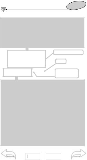
■ Page “00”, Starting page
When the instrument is switched on, the main page of variable displaying is shown. This first page, called page "00", is the only one configurable by the user who can choose the variables to be displayed in the 4 displaying areas. In all the other pages (up to 27 depending on the instrument configuration), the type of variables displayed in the four displaying areas is automatically selected and cannot be changed. In the table on page 41 you can see the contents of all the pages that can be displayed by WM3-96.
Measured variables
Clock
Number of the displayed page
The bottom part of the display, where the status of the digital outputs is indicated, is common to all the pages. If the outputs are not present, only an empty black rectangular frame is shown; if the outputs are present, the display will show a letter followed by a number. Four different letters may appear:
"P" Indicates a pulse output.
"A" Indicates an alarm output. In this case the letter can be white in a black background to indicate that the output is in alarm, or black in a white background to indicate that the output is not in alarm.
"D" Indicates a diagnostic output. This is a particular type of alarm that is activated when the neutral wire connection is missing. The alarm is active when the background is black, while the alarm is not active when the background is white.
"R" Remote control is activated (see Remote Control on page
34).
The number that follows the letter is the progressive number of the output (from 1 to 4).
To begin with
5 ▲
Pass 999
12
12 |
▲ |

8 |
Displaying of the variables |
|
■ How to scroll the various pages
To scroll the various pages, use the  and
and  keys.
keys.
Pressing the  key in any one of the display pages, you access to the programming phase. The
  key, on the contrary, has various functions depending on the selected page.
■How the F key changes function depending on the display page
Pages from "00" to "13" (04 in single phase mode) Displaying of the variables
 key enabled if the alarm latch function is activated, access to the reset of the latch alarms.
To reset the latch alarm press the  key; after that a message will appear "WILL YOU RESET THE LATCH
ALARMS?": if you choose  you will enable the reset procedure, if you choose
  there won’t be any reset. The reset of the latch alarm is only available if the alarm event is finished.
Pages from "14" to "18" (from 05 to 09 in single phase mode). Displaying of the MIN and MAX values
The  key is active, that means that you have access to the reset function of the “MIN” and “MAX” values. To reset the "MIN/MAX" recording, proceed as follows: enter the function by pressing the
  key, after that a message will appear: "WILL YOU RESET MIN/MAX VALUES, WILL
YOU CONTINUE?" If you choose  there won’t be any reset, if you choose
  the reset will not be made. The
  (moves from left to right) and
  (moves from right to left) keys allow you to select the value that you want to reset; to confirm the reset press the
  key. To exit the function press the
  key again.
Index
3 ▲
Energy meter pages
10
7 |
12 |
▲ |
|
|
|
|
Displaying of the variables |
9 |
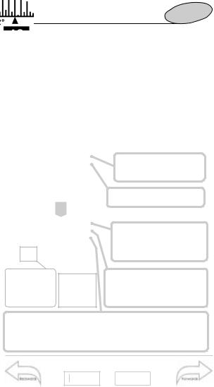
Pages from "19" to "24" (10 to 11 in single phase mode) Displaying of the harmonic analysis
When the instrument is supplied, these pages are not enabled, see page 29 to enable them.The  key is active, access to the detailed analysis of the harmonics. After pressing the
  key, a pointer appears along the horizontal axis (see figures below). To display the data relating to the single harmonics move along the histogram using the
  (moves from left to right) and
  (moves from right to left) keys. For each harmonic the instrument measures the % value with reference to the fundamental and the single harmonic angle between the "V" harmonic and the "A" harmonic of the same order.
The pointer shows which harmonic is being measured 
SIMPLE ANALYSIS:
Line phase being measured (L1-L2-L3) and relevant voltage or current value
Total harmonic distortion and relevant value in percentage
DETAILED ANALYSIS:
Harmonic order (h1 to h50) of the phase being measured (L1-L2-
L3) and relevant absolute current or voltage value of the harmonic.
Harmonic order (from h1 to h50), relevant conventional sign (– or +) and value of the harmonic given in percentage.
Phase angle between the voltage and current harmonic of the same order: a phase angle between 0° and 90° and between 270° and 360° corresponds to a generated harmonic; an angle between 90° and 180° and between 180° and 270° corresponds to an imported harmonic.
Page 00
7 ▲
Access to the main menu
13
7 |
12 |
|
|
|
|
|
10 |
Displaying of the variables |
||
|
|||
|
0° |
|
|
|
Generated |
|
|
|
Harmonics: 270° |
90° |
|
|
Imported |
|
|
|
180° |
|
|
|
This angle is displayed only if the measurements |
||
|
are taken in a three-phase system with neutral. |
||
Pages relating to the energy meters
Page "25" (12 in single phase mode) Displaying of the total energy meters
 key disabled.
Page "26" (13 in single phase mode)
Displaying of partial energies
 key is active; modification of tariff/displayed period. By pressing the
  key for the first time, the range relating to the season is highlighted. By using the
  and
and
 keys, it's possible to change the season displayed in that page. Pressing the
  key another time, the range relating to the period is highlighted. Using the
  and
and
 keys, it's possible to change the tariff period within the displayed season. Pressing the
  key for the third time, you go back to the measuring page. The changes of season and tariff period only refer to the displaying of the values stored in the corresponding season and period.
The changes carried out in this page do not have any influence on the method of tariff management of the instrument; they are only valid for display purposes.
To begin with
5 ▲
Pass 999
12
7 |
12 |
|
|
|
|
|

Displaying of the variables |
11 |
Page “27” (14 in single phase mode) Displaying of instrument configuration
 key disabled. Page 27 shows the configuration of the main input (IN) and output (OUT) modules.
Alarms
(A1-A2-A3-A4).
Diagnostics
(D1-D2-D3-D4).
Pulse outputs (P1-P2-P3-P4).
Digital inputs.
The letters and numbers between parenthesis are referred to the relevant slot, while the text on their right shows the variable referred to the output. With reference to the digital inputs (DIG.INP.), the ON/OFF status of each one of them is shown.
Displaying with access to the Pass Code
Pass "1000": displaying of recorded events (Only if the RS232+RTC module is present)
Press the  key: when the instrument asks you for the pass code
  , set the value "1000"; if the RS232+RTC module is present, the instrument shows you the page where the events are displayed and where the instrument stores, in a chronological order, the alarms that have occurred until that
moment. To go back to the variable page press the  key. The last event has always the number 1 while the number corresponding to the first event varies, depending on the number of events that have been previously stored. The figure on the following page explains you the meaning of the displayed information.
Harmonic analysis
9 ▲
CT ratio
15
7 |
12 |
|
|
|
|
|
12 |
Displaying of the variables |
|
Control type: alarm (e.g. A2),
diagnostics (e.g. D1), maximum value (MAX), minimum value (MIN).
Only for alarms and diagnostics: detection of the abnormal condition (ON) or return to the normal condition (OFF).
|
|
Variable being |
||
|
|
controlled. |
||
|
|
Alarms: value of |
||
|
|
the |
ON alarm; |
|
|
|
Max and MIN log- |
||
|
|
ging: maximum |
||
Date of the |
Time of the |
and |
minimum |
|
measured values. |
||||
event. |
event. |
|||
|
|
|||
To reset all the events press the  key, to continue the reset procedure press the
  key: to exit from the reset procedure press the
  key.
key.
Pass "999": energy consumption storage (Only if the RS232+RTC module is present)
The RS232+RTC module allows also the storage of the energy consumption of the previous two months. To enter this function, press the  key: when the instrument asks for the pass code
  , set the value "999": the instrument shows you the page where all the information are stored.
Page 00
7 ▲
7
System
14
Let’s start 13
Use the  and
and  keys to show the partial values, to exit press the
  key.
key.
It is very important to verify that, every time the configuration of the instrument (modules and/or associated variables, electrical systems, etc.) changes, the setting of the parameters is according to the new configuration.
1.2..
..2.1
Instrument revision
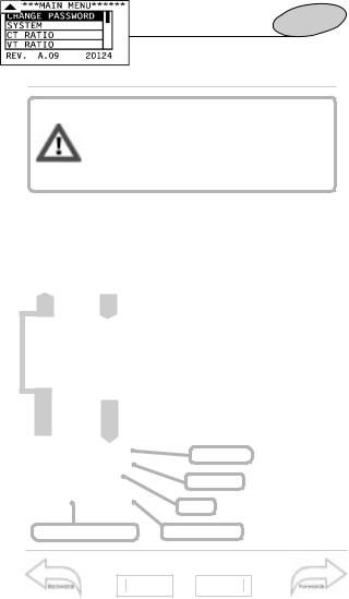
■ Access to the main menu
Press the  key to access to the programming menus from the measuring and displaying phase; when the instrument asks for it, enter the correct password value by means of the
  and
and  keys; then confirm it pressing the
  key again. If the password is correct (the default password is 0) you are allowed to access to the main menu of the programming phase. To reset your choice and go back to the measuring mode, press
  .
.
MENU title
Scroll bar
Menu
Serial number
Pass 1000
11 ▲
Min/Max values
17
21 |
▲ |
|
14 |
Let’s start |
|
|
|
■ Changing the password |
1.2..
Measure ..2.1
This function allows you to choose the desired password value (from 0 to 500).
Press the  key and when the new password value is required, enter the desired value by means of the
  and
and  keys.
keys.
The instrument goes back to the main menu, as shown on the figure on the left. To reset your choices and go back to the main menu press  .
.
Measure
Harmonic analysis
9
▲
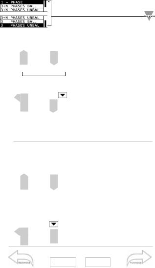
■ System
This function allows the user to select the type of electrical system by choosing among single phase (1- phase), balanced three-phase plus neutral (3+N phases bal.), unbalanced three-phase plus neutral (3+N phases unbal), three-phase balanced (3 phases bal) and threephase unbalanced (3 phases unbal). Choose the SYSTEM function by means of the  and
and  keys, press
  to confirm; then select the desired system by means of the
and  keys and confirm with
  .
.
VT ratio
16
13 |
21 |
▲ |
|
|
|
|
Let’s start 15
To reset the choice and go back to the main menu, press the  key.
key.
Changing the type of system, all the MIN/MAX values, the events and the partial energy meters are reset.
1.2..
..2.1
Measure
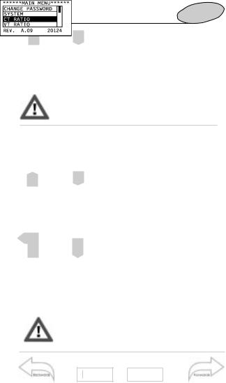
■ CT ratio
This function allows you to select the value of the CT ratio. Example: if the primary of the CT (current transformer) being connected is 300A and the secondary is 5A, the CT ratio corresponds to 60 (obtained from the calculation: 300/5). Choose the function CT RATIO by means of the  and
and  keys; press
  to confirm, then select the desired value by means of the
  and
and  keys and confirm with
  . To reset the choice and go back to the main menu, press
  .
.
Note that when the CT ratio is changed all the MIN/MAX values, the events and the partial energy meters are reset.
Energy meters
10 ▲
Average power calculation
19
13 |
21 |
▲ |
|
|
|
|
16 |
Let’s start |
|
|
|
|
|||||
|
|
|
|
|
|
|
||||
|
|
|
|
|
|
■ VT ratio |
|
|
|
|
|
|
|
|
|
|
This function allows the user to se- |
||||
|
|
|
|
|
|
lect the multiplier value of the VT. |
||||
|
|
|
|
|
|
Example: if the primary of the VT |
||||
|
|
|
|
|
|
(voltage transformer) being con- |
||||
|
|
|
|
|
|
nected is 20kV and the secondary |
||||
|
|
|
|
|
|
is 100V, the VT ratio will be 200 |
||||
|
|
|
|
|
|
(given by 20000/100). If there is no |
||||
|
|
|
|
|
|
|||||
|
|
|
|
|
|
VT, the ratio will be “1.0”. |
||||
|
|
|
1.2.. |
|
Choose the function VT RATIO by |
|||||
|
|
|
|
means of |
|
and |
; to confirm |
|||
|
|
|
..2.1 |
|
|
|||||
|
|
|
|
|
|
press |
; then select the desired |
|||
|
|
|
|
|
|
value by the |
and |
keys and |
||
|
|
|
|
|
|
confirm with |
. To reset your |
|||
|
|
|
|
|
|
choice and go back to the main |
||||
|
|
|
|
|
|
menu, press |
. |
|
|
|
Changing the VT ratio, all the MIN/MAX values, all events and partial energy meters are reset.
Pass 1000
11 ▲
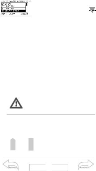
■ Display page
This function allows you to select the variables to be displayed on page
00. Choose the DISPLAY PAGE function by means of the  and
and  keys; press
  to confirm, then select the desired section of the display using the
  and
and  keys;
keys;
|
|
|
Event selection |
|
13 |
|
21 |
18 |
|
|
||||
|
▲ |
|
||
|
|
|
|
|
Let’s start 17
Press  ; select the variable to be displayed by means of the
  and
and  keys and confirm it with
  .
.
To reset your choices and go back to the main menu press  .
.
Measure
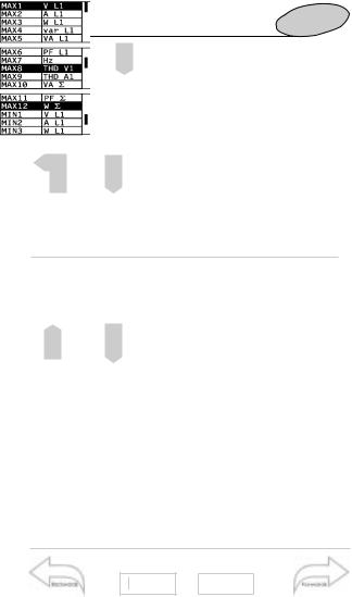
■ MIN/MAX VALUES
This function allows the user to associate some variables to the automatic recording of maximum values
(from MAX1 to MAX12) and minimum values (from MIN1 to MIN8). To use this function, proceed as follows: select the MIN MAX VALUES function using the  and
and  keys and confirm it with
  .
.
A new window will appear showing you the list of available memory locations: select the locations using the  and
and  keys, starting from MAX1 for the maximum values and MIN1 for the minimum values. Press
 to open the secondary menu with the list of the available variables to be selected.
CT ratio
15 ▲
Average power calculation
21
13 |
21 |
▲ |
|
|
|
|

18 |
Let’s start |
|
CT ratio
15 ▲
Scroll the list of the variables using the  and
and  keys; once you have selected the desired variable, confirm it using
  . To reset your choices and go back to the main menu, press
  .
.
Once you have confirmed the selection, the following message
will appear: “YOUR CHOICE WILL RESET THE VARIABLE, WILL YOU
CONTINUE? YES/NO”. Note: to enable the MIN/MAX recording function, read carefully the following paragraph, SELECTING THE EVENTS.
■ Selecting the events
This function allows the user to enable the events for data logging:
•MAX (logging of up to 12 different variables MAX1 to MAX12), see also: MIN MAX VALUES;
•MIN (logging of up to 8 different variables MIN1 to MIN8), see also
MIN MAX VALUES;
•D ”diagnostics” (logging of up to 4 alarms: from D1 to D4), see also: DIAGNOSTIC DIGITAL OUTPUTS
•R “remote control” (up to 4 remotely controllable outputs: from R1 to R4), see also REMOTE CONTROL DIG-
ITAL OUTPUTS;
•A "alarms" (logging of up to 4 alarms: from A1 to A4), see also:
ALARM DIGITAL OUTPUTS;
|
|
|
Synchronization |
|
13 |
|
21 |
20 |
|
|
||||
|
▲ |
|
||
|
|
|
|
|
1.2..
..2.
Min / Max values
17
▲
Let’s start 19
To use this function, select “EVENTS SELECT.” from the main menu using the  and
and  keys and confirm it pressing
  . Use the
  and
and  keys to select where you want to enable the event (ON) or disable it (OFF). The function of the
  ON-
ON-
OFF-ON key is cyclical. To go back to the main menu press  .
.
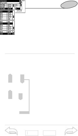
■ Average power calculation
This function allows to select the calculation method of the W-VA-cosϕ average value.
To enter these functions, select “AV-
ERAGE CALCULATION” from the main menu by means of the  and
and  keys and confirm the selection pressing the
  key.
key.
You can now choose the average calculation method, that is you can choose between FIXED and FLOAT SELECTION using the  and
and  keys. Confirm your choice using the
 key. Then, you can set the integration time period; again, use the
  and
and  keys to set the desired value and confirm it with
  .
.
To reset your choices and go back to the main menu, press  .
.
Energy Meters Management
23
13 |
21 |
▲ |
|
|
|
|
20 |
Let’s start |
|
FIXED SELECTION: if, e.g., you set this value at 15 minutes, the instrument calculates and updates the average of the variables (W-VA-PF) every 15 minutes.
FLOAT SELECTION: if, e.g., you set this value at 15 minutes, the instrument at first calculates and updates the average of the variable (W-VA-PF) after 15 minutes and then every minute (fixed time).
See the diagram that shows the different operating methods (FIXED and FLOAT) on the following page.
SYNCHRONIZATION OF THE FIXED OR FLOAT CALCULATION
The synchronization of the FIXED or FLOAT calculation can be carried out in three different ways:
•without the DIGITAL INPUT and RS232 + RTC modules: the reset and the beginning of the synchronization is carried out as soon as the instrument is powered on;
•with the installed DIGITAL INPUT module:
the synchronization begins when the digital input modules change state (from ON to OFF or from OFF to ON). Any following change of state will make the synchronization reset and start all over again;
•with the RS232+RTC module:
the synchronization begins at the exact hour that follows the switch on of the instrument (E.g.: if the instrument is switched on at 10:25, the synchronization begins at 11:00).
In case both modules are installed (that is digital inputs and RS232+RTC) the priority will be given to the Digital Input modules.
CT ratio
15 ▲
Energy Meters Management
22
13 |
21 |
▲ |
|
|
|
|
 Loading...