

Page 1

Instruction Manual
Display, Programming
Modular system
Class 0.2 A/V
Page 2

CARLO GAVAZZI
Automation Components
Thank you for choosing our products
WM30 96:
• High accuracy (class 0.2 A/V);
• High calculation performances for a fast analysis
of the signal (FFT up to the 32
• high connection capabilities.
WM30-96 is the state-of-the-art tecnological
answer to your needs of power quality analysis.
nd
harmonics);
1
Moreover, you can count on a ISO9001/VISION
2000 certified company structure, an experience of many years and a wide-spread presence both in Europe and all over the world. All
this in order to guarantee the customer with a
top-quality service and the best products.
Welcome in Carlo Gavazzi and our compliments for your choice. You can evaluate the
complete range of our products on the CARLO
GAVAZZI web-site:
www.gavazzi-automation.com
Page 3

CARLO GAVAZZI
Automation Components
INTRODUCTION TO WM30
DESCRIPTION OF THE INSTRUMENT
1
Active virtual alarms warners.
3
4
2
Current energy drain indicator (kWh) by means of flashing, proportional to the measured energy (the
higher the flashing frequency, the higher the energy drained. Max. frequency 16Hz pursuant to standard EN5047-1).
2
5
6
7
1
2
ADDITIONAL FUNCTIONS OF THE BUTTONS
The buttons featuring a double icon have two functions, to access the secondary function,
hold pressed for a long time the button corresponding to the desired secondary function.
Access to the instrument information screens: reference standards, firmware version, year of manufacturing.
8
9
10
The keyboard is divided into two areas, the top area is dedicated to the measurements with direct access
to specific visualization screens.
3
Visualization of the counters screens: each pressure of the button corresponds to the visualization of
a screen with counters related to different energies (see the table with the measurement screens
below).
4
Visualization of the current voltage and frequency (see the table with the measurement screens below).
5
Visualization of the instant cosf and powers (see the table with the measurement screens below).
6
Visualization of the harmonics (see the table with the measurement screens below).
The keyboard in the bottom area is especially dedicated to instrument programming.
7
Exits the submenus, exits programming.
8
“Up” button, enables to browse the menus and to increase the values to be set.
9
“Down” button, enables to browse the menus and to decrease the values to be set.
10
Access to the programming menu:
ming menu.
In measurement mode, buttons 8 and 9 enable to display the MAX and dmd values of the displayed
variables.
hold pressed for at least 2 seconds to access the program-
“Home” button: from any measurement screen, from any menu, returns to the
main measurement screen (customizable by the user).
ming menu, any data entered is lost.
Holding pressed the button 8, you access the reset of the MAX of the displayed
variables.
Holding pressed button 9, you access the reset of the dmd's of the displayed
variables.
The reset must be confirmed by button 10.
If you are in the program-
The buttons are enhanced touch buttons. To check their actual engagement, a specific icon on the
display turns on each time a button is pressed.
Page 4

CARLO GAVAZZI
Automation Components
INTRODUCTION TO WM30
3
1
2
3
4
5
6
ICONS OF THE DISPLAY
7
8
LINE 1LINE 2LINE 3LINE 4LINE 5
9
DESCRIPTION OF THE DISPLAY
1
Graphic bar which displays the active and the apparent power drained with relation to the installed
power.
2
Indications of inductive phase displacement L, -L, or capacitive phase displacement C, -C.
3
Indication of the measurement phase-neutral L1 or phase-phase L12.
4
Indication of the measurement phase-neutral L2 or phase-phase L23 or of the asymmetry phasephase VLL.
5
Indication of the measurement phase-neutral L3 or phase-phase L31 or of the asymmetry phaseneutral VLn.
6
Indication of the engineering unit and of the multiplier: k, M, V, W, A, var (VAr), PF (Pf), Hz, An.
7
ALR: the alarm display function is active. PROG: the programming function is active.
8
Area dedicated to the visualization of counters, text messages, date and time (format:
dd.mm.yy/hh:mm). Energy counters (see table on the following screen).
9
Indication of: dmd, THD% or Max.
10
Indicates that all the instant values displayed are system values.
11
Phase sequence error alarm.
12
Instrument programming enabled.
13
Instrument programming disabled.
14
Data transmission (TX) and reception (RX), via network communication, in progress.
10 11 12 13 14
ALARM SETPOINT
Up alarm. Down alarm.
Notes: the display is backlighted with lighting time programmable from 0 minutes (always on) to 255
minutes.
Page 5

CARLO GAVAZZI
Automation Components
Selection Application Note
A Cost allocation Imported energy metering
B Cost control Imported and partial energy metering
C Complex cost allocation Imported/exported energy (total and partial)
D Solar
E Complex cost and power analysis
F Cost and power quality analysis Imported energy and power quality analysis
G Advanced energy and power analysis for power generation Complete energy metering and power quality analysis
“EASY PROG” FUNCTION, choosing the application
Imported and exported energy metering with some basic
power analyzer function
Imported/exported energy (total and partial) and power
analysis
4
NOTE
WM30-96 is provided with the “Easy-prog” function which enables a simple, quick, clear and immediate visualization of the instrument measurements, making available only specific variables depending on the application of the instrument. The available applications are described above.
To leverage all the capacities of the instrument, select the application G which enables a complete and detailed analysis of the electric energy.
Page 6

CARLO GAVAZZI
Automation Components
DISPLAY PAGES
5
No Line 1 Line 2 Line 3 Line 4 Line 5 Note
Total kW (+) Programmable x x x x x x x
0
Total kW (+)
1
Total kvarh (+) x x x x x x x
2
Total kWh (-) x x x x
3
Total kvarh (-) x x x x
4
kWh (+) part. x x x x x
5
kvarh (+) part. x x x x x
6
kWh (-) part. x x x
7
kvarh (-) part. x x x
8
Run Hours
9
(99999999.99)
Phase seq.
10
Phase seq.
11
Phase seq. An AL1 AL2 AL3 x x x x
12
Phase seq. Hz “ASY”
13
Phase seq.
14
Depending on the last displayed page of
instantaneous variables.
VLN ∑
VLN ∑
VA ∑
VL1 VL2 VL3 x x x x
VL1-2 VL2-3 VL3-1 x x x x
VA L1 VA L2 VA L3 x x x
VLL sys
(% asy)
VLL sys
(% asy)
A B C D E F G
x x x x x x x
Application
x x x x x
x x x x
Phase seq.
15
Phase seq.
16
Phase seq.
17
Phase seq. THD V1 THD V2 THD V3 x x
18
Phase seq. THD V12 THD V23 THD V31 x x
19
Phase seq. THD A1 THD A2 THD A3 x x
20
var ∑
W ∑
PF ∑
var L1 var L2 var L3 x x x
WL1 WL2 WL3 x x x x
PF L1 PF L2 PF L3 x x x
Page 7

CARLO GAVAZZI
Automation Components
INFORMATION PAGES
6
No
1
Conn. xxx.x (3ph.n/3ph/3ph./
2
3
PULSE out1 (text) kWh/kvarh xxxx kWh/kvarh per pulse +/- tot/PAr x x x x x x x
4
PULSE out2 (text) kWh/kvarh xxxx kWh/kvarh per pulse +/- tot/PAr x x x x x x x
5
6
7
8
9
10
11
12
13
14
Line 1
Lot n. (text) xxxx Yr. (text) xx SYS (text) x (1/2/3) 1...60 (min) “dmd” x x x x x x x
3ph.2/1ph/2ph)
LED PULSE (text) kWh xxxx kWh per pulse x x x x x x x
Remote out out1 (text) on/oFF Out2 (text) on/oFF x x x x x x x
Alarm 1 nE/nd None / out 1 / out 2 Set 1 Set 2 (measurement) x x x x
Alarm 2 nE/nd None / out 1 / out 2 Set 1 Set 2 (measurement) x x x x
Alarm 3 nE/nd None / out 1 / out 2 Set 1 Set 2 (measurement) x x x x
Alarm 4 nE/nd None / out 1 / out 2 Set 1 Set 2 (measurement) x x x x
Analogue 1 Hi:E 0.0 ... 9999 Hi.A 0.0 ... 100.0% x x x x
Analogue 2 Hi:E 0.0 ... 9999 Hi.A 0.0 ... 100.0% x x x x
COM port None / out 1 / out 2 xxx (address) bdr (text)
IP address XXX XXX XXX XXX x x x x x x x
Line 2 Line 3 Line 4 Line 5 Note
CT.rA (text) 1.0 … 99.99k PT.rA (text) 1.0...9999 x x x x x x x
9.6/19.2/
38.4/115.2
A B C D E F G
x x x x x x x
Applications
Page 8

CARLO GAVAZZI
Automation Components
Measuring
mode
PROGRAMMING WM30-96
7
Key-pad
Push for at
least 2 s
See details on the next
page.
NOTE
10 CHANGE PAS: this function allows the user to modify the PASS value
with a new value (from 0 to 1000).
20 BACKLIGHT: backlight time from 0 (always on) to 255 minutes.
30 MODULES: the WM30 96 does not support the automatic ackno-
wledgment of the installed modules, therefore this information must be
entered using the “MODULES” menu.
40 APPLICAT.: this function which enables a simple, quick, clear and
immediate visualization of the instrument measurements, making available
only specific variables (page 4/5) depending on the application of the
instrument.
electrical system.
value of the CT ratio (primary/secondary ratio of the current transformer
being used). Example: if the CT primary (current transformer) has a current
of 300A and the secondary a current of 5A, the CT ratio corresponds to 60
(obtained using the following calculation: 300/5.
70 PT RATIO: this function allows you to select the value of the VT-PT ratio
(primary/secondary ratio of the voltage transformer being used). Example:
50 SYSTEM: this function allows the user to select the type of
60 CT RATIO: this function allows the user to select the
Page 9
if the primary of the connected VT (voltage transformer) is 20kV and the
secondary is 100V, then the VT-PT ratio corresponds to 200 (obtained carrying out the following calculation: 20000/100).
80 DMD: This function allows the user to select the calculation method of
the DMD/AVG value of the selected variable. 81 TYPE: select the type of
calculation mode to be used for the DMD/AVG calculation FIXED: if, for
example, a time interval of 15 minutes has been selected, the instrument
will calculate the AVD/DMD value of the measured variable and updates its
value every 15 minutes. SLIDE: if for example a time interval of 15 minutes has been selected, the instrument calculates the AVG/DMD value and
updates its value at the beginning after the first 15 values and then after
every minute, thus generating a window whose width is of 15 minutes and
that moves forward every minute. 82 TIME: select the time interval for the
DMD/AVG calculation 83 SYNC: select the synchronization mode, that is
the method that controls the calculation method of the average/demand
according to the selected time.
90 SET POWER: This menu allows you to set a power value (installed power)
that, in the measuring phase, will represent 100% of the graph indicator.
100 HOME PAGE: This function allows the user to select the variables to
be displayed on first page (home page). 101 TYPE: A, you can select the
variable for each row. B, you can select a preset combination of variables.
110 FILTER: Thanks to the digital filter, it’s possible to stabilize the measurements which are too instable when displaying the relevant values. 111
FILTER S: set the operating range of the digital filter. The value is expressed as a %. 112 FILTER CO: set the filtering coefficient of the instantaneous measures. By increasing the value, also the stability and the settling
time of the measures are increased
Some specific menus display only if the relevant modules are installed
Self-recognize.
*
.
Page 9

CARLO GAVAZZI
Automation Components
PROGRAMMING WM30-96
8
E
Row 2
Row 1
C
D
D
D
D
E
C D
Type Selection 0 1 2 3 4 5 6 7 8 9 10 11
Type A AN W var VA PF Hz AN AN AN AN AN AN
Type A with
System
V1 A1 W1 var1 VA1 PF1 Hz V1 V1 V1 V1 V1
1P
Type B Select one of the preset combination of variables
Type B with
System 1P
Select one of the preset combination of variables
How to costumize the home page of WM30-96
Menu “101 TYPE”: A, you can select the variable for each row. B, you can select a preset combination of variables. Moreover, the selectable variables depend on the selected electric system,
if 1P (one phase) system is selected, the available variables are different.
Note: when the B type is selected all the A selections on row 3, 4, 5 are irrilevant.
E
Row 2
Row 3
Row 4
Row 5
0 1 2 3 4 5 6 7 8 9 10 11
V
LN
LN
-
L2VL2-3AL2
-
L3VL3-1AL3
∑
V
∑
V
V
V
∑
LN
V
L1-2AL1
An Hz
“ASY”
VLL sys
(% asy)VAL2
VLL sys
(% asy)VAL3
D
VA ∑ var ∑ W ∑ PF ∑
VAL1varL1W
L1PFL1
varL2W
L2PFL2
varL3W
L3PFL3
- - -
THDV1THD
THDV2THD
THDV3THD
V12
V23
V31
THD
A1
THD
A2
THD
A3
Row 3
Row 4
Row 5
Type A AN W var VA PF Hz AN AN AN AN AN AN
Type A with
System 1P
V1 A1 W1 var1 VA1 PF1 - - - - - -
Type A VL-L AN W var VA PF VL-L - - - - -
Type A with
System 1P
V1 A1 W1 var1 VA1 PF1 Hz - - - - -
Type A VL-N AN W var VA PF VL-L - - - - -
Type A with
System
V1 A1 W1 var1 VA1 PF1 Hz - - - - -
1P
E
Row 2
Row 3
Row 4
Row 5
D
0 1 2 3 4 5 6 7 8 9 10 11
V 1 VA THD_V1
A 1 VAR 1 THD_A1
Hz W 1 -
- PF 1 -
Page 10
CARLO GAVAZZI
Automation Components
PROGRAMMING WM30-96
9
Page 7 (110)
list of available
variables
As V ALARM 1
As V ALARM 1
As V ALARM 1
As DIG OUT 1
Key-pad
Push for at
least 2 s
list of available
variables
NOTE
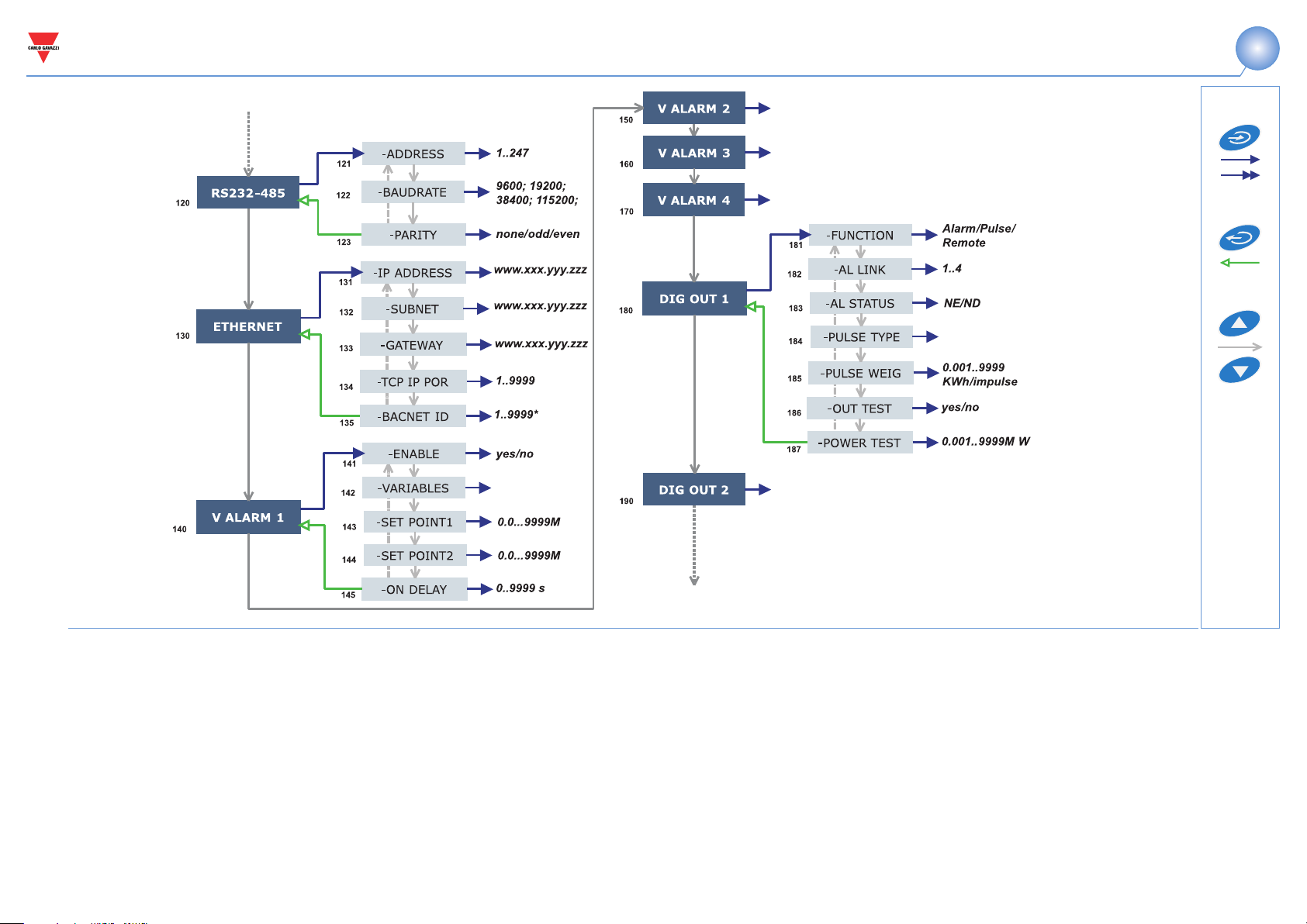
120 RS232-458: This function allows the user to set the RS232 and RS485
serial ports as well as the optical port.
130 ETHERNET: This function allows the user to set the Ethernet port.
140 V ALARM 1: This function allows you to set the alarm parameters. 141
ENABLE: enable (YES) or disable (NO) the alarm. 142 VARIABLES: set the
variable to be coupled to the alarm. 143 SET POINT 1:set the first alarm
set point of the variable. 144 SET POINT 2: set the second alarm set point
of the variable. 145 ON DELAY: set a delay on activation of the alarm.
180 DIG OUT 1: This function allows the selected function to be coupled
to the selected digital output. 181 FUNCTION: Alarm, the digital output is
enabled only if the expected alarm status occurs. Pulse, the measured
energy is retransmitted by the digital output by means of pulses.
Remote,
Page 10 (200)
the digital output can be enabled by means of a command sent by means
of serial port. 182 AL LINK: select the reference alarm. 183 AL STATUS:
“ND” (normally de-energized relay) or “NE” (normally energized relay) 185
PULSE WEIG: selects the pulse weight (kWh per pulse). 186 OUT TEST:
active the TEST (YES), deactivate the TEST (NO). 187 POWER TEST: sets
the simulated power value (kW) to which a proportional pulse sequence
according to “PULSE WEIG” corresponds. The function is active until you
remain within the menu.
Some specific menus display only if the relevant modules are installed.
Page 11

CARLO GAVAZZI
Automation Components
PROGRAMMING WM30-96
10
Page 9 (190)
Key-pad
List of available
variables
Push for at
least 2 s
As AN OUT 1
Save the set
parameters and come
back to the measuring
mode.
NOTE
200 AN OUT 1: this submenu allows the programming of the analog outputs (0-20mA, 0-10V). 201 VARIABLES: select the variable to be retransmitted by means of the analog output. 202 MIN OUT: set the value
expressed as % of the output range (0-20mA, 0-10V) to be coupled to the
minimum measured value. 203 MAX OUT: select the value expressed as %
of the output range (0-20mA, 0-10V) to be coupled to the maximum measured value. 204 MIN INPUT: minimum value of the variable input range to
which the “MIN OUT” value, retransmitted by the analog output, will be
coupled. 205 MAX INPUT: maximum value of the variable input range to
which the “MAX OUT” value, retransmitted by the analog output, will be
coupled.
220 METERS: reset the ENERGY METERS choosing among: TOTAL,
PARTIAL: resets all energy meters, both total and partial. TOTAL +: resets
the total meters of imported energy. TOTAL -: resets the total meters of
exported energy. PARTIAL +: resets the partial meters of imported energy.
PARTIAL -: resets the partial meters of exported energy.
Page 7 (10)
230 RESET: carry out the reset of the MAX or dmd stored values.
240 CLOCK, 241 FORMAT: UE, set the time format as 24h european
(00:00) or USA as 12h american (12:00 AM). 242 TIME: set the current
time. 243 DATE: set the current date.
Some specific menus display only if the relevant modules are installed.
Page 12

CARLO GAVAZZI
Automation Components
DIGITAL FILTER PROGRAMMING EXAMPLES
PROGRAMMING WM30-96
11
Example 1
How to stabilize the value of the VL-N variable displayed on the display, fluctuating from 222V and 228V.
The parameters of the digital filter have to be programmed as follows:
FILTER S: the variable has fluctuations within the mean value whose
amplitude is equal to ±0,75% of the full scale rated value of the variable
itself (obtained by the following calculation: (228-222)/ 2= ±3V, then
±3*100/400V= ±0,75% where 400V is the phase-neutral rated value of an
AV5 input). The “range” parameter, representing the action range of the
digital filter, is to be programmed to a value which must be slightly higher than the percentage amplitude of the fluctuation: ex. 1.0%.
FILTER CO: if the new value measured by the instrument is within the
action range of the filter, the new displayed value is obtained by adding
algebrically the previous value to the variation divided by the filtering
coefficient. As a consequence, a value higher than this coefficient implies
a longer settling time and therefore a better stability. You generally obtain
the best result by setting the filtering coefficient to a value equal to at
least 10 times the range parameter value.
In the following example: 1,0*10=10, the stability of the filtering coefficient can be improved by increasing the filtering coefficient, the admitted
values are included within 1 and 255.
Example 2
How to stabilize the value of the displayed System Active Power
(W∑), fluctuating between 300kW and 320kW (the load is connected
to the instrument by means of a 300/5A CT and a direct measure of
the voltage).
The parameters of the digital filter must be programmed as follows:
FILTER S: the variable has fluctuations within the mean value whose
amplitude is equal to ±2,78% of the full scale rated value of this variable.
This value is obtained by the following calculation: (320-300)/ 2= ±10kW,
then ±10*100/360kW= ±2,78%, where 360kW is the rated value of the
System Active Power of an AV5 input, at the above mentioned CT and VT
ratios and obtained by means of the following formula: (320-300)/ 2=
±10kW, then ±10*100/360kW= ±2,78%, where 360kW is the rated value
of the System Active Power of an AV5 input
at the above mentioned CT and VT ratios and obtained by means of the
following formula: “VLN * VT * IN * CT * 3” where VLN = rated input voltage (400V for the AV5 input), VT= primary/secondary ratio of the voltage
transformer being used, IN = rated current (5A for the AV5 type input), CT
= primary/secondary ratio of the voltage transformer being used (in this
example “400*1*5*60*3=360kW).
The RANGE parameter, representing the digital filtering coefficient action
range, is to be programmed to a value which must be slightly higher than
the percentage of the fluctuation: ex. 3.0%.
FILTER CO: if the new value acquired by the instrument is within the filtering
action range, the new displayed value is obtained by adding algebrically the previous value to the variation divided by the filtering coefficient. As a consequence,
a value higher than this coefficient implies an higher settling time and therefore a
better stability. Generally speaking the best result is obtained setting the filtering
coefficient to a value equal to at least 10 times the value of the range parameters.
In the example: 3.0*10=30. In order to improve the stability you can increase the
filtering coefficient, the admitted values are included within 1 and 255.
Example 3.
It’s necessary to stabilize the value of the displayed variable AL 1
(phase current 1), fluctuating within 470V and 486V.
To be able to manage the alarm function and following activation and
deactivation of the relay, this value is not to be subject to continuous
fluctuations. In this example we have considered using a 500/5A CT. The
paramters of the digital filter is to be programmed as follows:
FILTER S: the variable has fluctuations within the mean value whose
amplitude is equal to ±1,60% of the full scale rated value of this variable
(obtained by means of the calculation: (486-470)/ 2= ±8A, then
±8*100/500V= ±1,60% where 500A is the value referred to the primary of
the transformer being used). The “range” parameter, which represents the
action range of the digital filter, is to be programmed to a value slightly
higher than the pourcentage amplitude of the fluctuation: for example
2.0%.
FILTER CO: if the new value acquired by the instrument is within the filtering action range, the new displayed value is calculated algebrically
adding to the previous value the variation divided by the filtering coefficient. As a consequence, a higher value of this coefficient implies a higher settling time and therefore a better stability. Generally speaking, the
best result is obtained setting the filtering coefficient at a value equal to
at least 10 times the value of the range parameter. In the example:
2.0*10=20. To improve the stability you can increase the filtering coefficient, the admitted values are within 1 and 255.
Page 13

CARLO GAVAZZI
Automation Components
PROGRAMMING EXAMPLES OF THE ANALOGUE OUTPUTS
PROGRAMMING WM30-96
12
Power retransmission by means of a 0-20mA analog output.
It’s necessary to measure a consumed power up to 100kW and retransmit this value by means of a signal from 4 to 20 mA: the module to be
used is AO2050 (2x from 0 to 20mA), the instrument is to be programmed
as follows:
VARIABLE: W∑ (system active power).
MIN OUT: 20.0% means 4 mA the calculation to be carried out is the fol-
lowing: (100*minimum output) / fullscale output =100*4mA/ 20mA=20%.
MAX OUT: 100.0% means 20mA, the calculation to be carried out is:
(100*maximum output) / fullscale output = 100*20mA/20mA= 100.
MIN INPUT: 0,0k; the multiple k,M,G can be selected on the instrument
according to the chosen VT and CT values.
MAX INPUT: 100.0k; the k, M, G multiples can be selected on the instrument according to the selected VT and CT values.
Retransmission of the POWER FACTOR (PF) by means of the
0-20mA analog output.
It’s necessary to retransmit the whole range of the admitted values for the
PF with a signal from 0 to 20mA. Particular attention must be paid to the
value of the PF variable which may vary from C0,001 and L0,000 (for each
phase): these values will be retransmitted and will then correspond to 0
and 20 mA. When the PF will have a value equal to 1, being in the middle between C0,001 and L0,000, the value of the output will correspond
to the middle of the scale, that is 10mA. As a consequence, the instrument will have to be programmed as follows:
VARIABLE: PF L1 (or L2 or L3 or PF∑).
MIN OUT: 0,0%.
MAX OUT: 100,0%.
MIN INPUT: C0,001 (the C symbol shows a CAPACITIVE value).
MAX INPUT: L0,001 (the L symbol shows an INDUCTIVE value). L0,001
has been chosen as minimum value to be set in order to avoid any undesirable swifting of the repeated outputs.
Page 14
CARLO GAVAZZI
Automation Components
EXAMPLE OF ALARM PARAMETERS PROGRAMMING
300kW
295kW
PROGRAMMING WM30-96
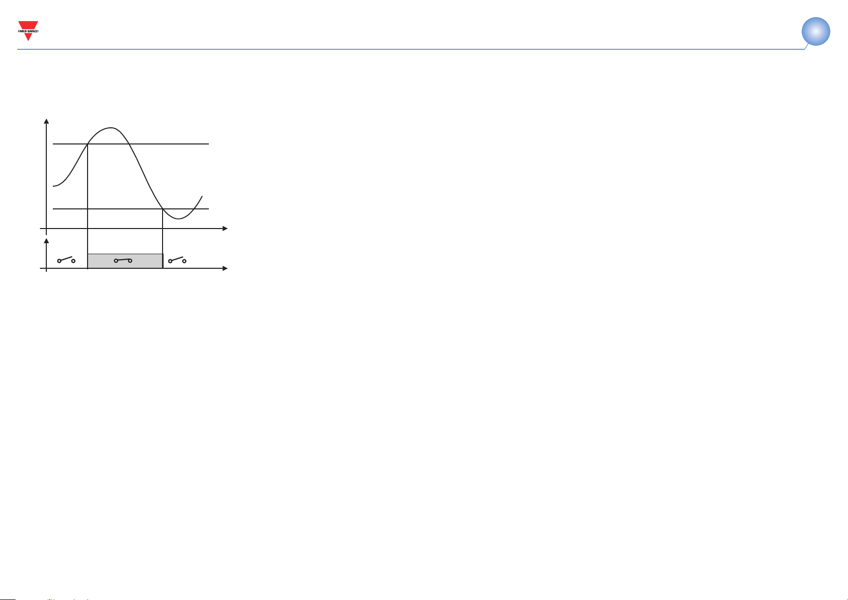
The disconnection of a load when a set value of absorbed power is
required. For example when 300kW are exceeded, the alarm occurs and
a set load is disconnected. An UP alarm is selected. Below you’ll find the
recommended programming:
ENABLE: YES
VARIABLES: W system (W∑)
SET POINT 1: 300kW
SET POINT 2: 295kW
ON DELAY: set the desired number of seconds: “5 seconds”.
13
Page 15

www.GavazziOnline.com
 Loading...