

Page 1
The utility distribution system allows greater flexibility over conventional utility connections. It is designed to provide
(800) 965
-
0420
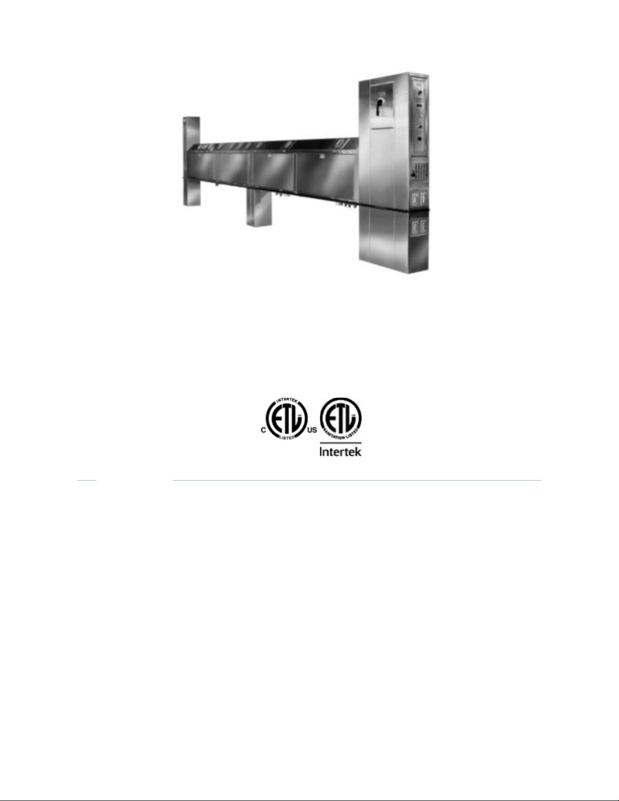
Utility Distribution System
CaptiveAire Systems' UDS provides
unequaled cooking line versatility, flexibility
and convenience.
One connection for all your utility needs
The CaptiveAire Utility Distribution System (UDS) is designed to meet all electrical and plumbing requirements for
your kitchen appliances. A two compartment raceway houses either an electric copper bus bar or wireway which is
completely isolated from the plumbing supply manifolds.
ADVANTAGES
Efficiency for Today - Flexibility for Tomorrow
additional capacity according to job specifications. Spare connection points are provided for future cooking
equipment expansion; therefore adding new equipment requires minimal effort. Rearranging the cooking line-up
can be accomplished in a matter of minutes, especially when equipment is on casters.
Electrical Riser: Main power connection is made to the main circuit breaker which has a shunt trip and is mounted
in the electrical riser.
Bus bar systems: Electrical power is fed through the main circuit breaker to the bus bar system in the raceway.
Each appliance is fed from the bus bar through individually sized circuit breakers located along the raceway.
Wireway systems: Electrical power is fed through a main circuit breaker to a distribution panel which contains
individual branch breakers. Each appliance is fed from the individual breakers which are wired to each receptacle
located along the raceway.
Plumbing Riser: The plumbing riser houses manual (quarter-turn) shut-off valves for each incoming main supply
line located in the UDS. The plumbing manifolds are provided with stub-outs along the raceway for the individual
plumbing connections. Each stub-out is equipped with a manual (quarter-turn) shut-off valve.
Page 2

FEATURES
(800) 965
-
0420
ETL Listed to US and Canadian Standards and ETL Sanitation Listed
2 Models Available:
UDI: Island configuration with equipment connections on both sides
UDW: Wall mounted with equipment connections on one side only.
Expandability: All plumbing manifolds are provided with multiple plumbing stubs for future use. All
electrical systems are designed for additional capacity for future expansion or upgrade of connected
appliances.
Bus Bar Systems: Individual circuit breakers mounted on interchangeable plates for ease of service and
relocation. Spare connection points provided for cooking equipment relocation or expansion.
Wireway: Electrical distribution panel located in the riser is equipped with branch circuit breakers and sized
for expansion.
Serviceability and Accessibility: Lift out doors provide easy access to risers without moving cooking
equipment, in most cases. Removable panels provided along the length of the raceway allow access to
either plumbing or electrical compartments.
Electric Outlets and Cord Sets: All outlets are provided with moisture resistant covers and have been
sized per NEMA standards. Each is supplied with a matching cord and plug set if these are not already
supplied by the equipment manufacturer. Twist-lock sets are standard with the model UDI. Straight blade
sets are standard with the model UDW.
Main Disconnect: One point disconnect through a main circuit breaker equipped with a 120 VAC rated
shunt trip provided in the riser.
Gas Solenoid Valve: Electrical or Mechanical. Electrical valves provided with a manual reset button.
Shunt Trip: Provided with each main breaker.
Appliance Protection: Each electrical outlet connection is protected with an individual circuit breaker.
Dual Convenience Outlets: Located at each riser with integral ground fault protection.
Fire/Fuel Shutoff: In compliance with NFPA 96, terminal connection points provided for field wiring to the
fire protection system to shut off fuel sources and power in the event of a fire.
Customized CAD Drawings Provided
OPTIONS
Remote Status Indicator Panel: Lighted panel indicates status of breakers in wireway system.
Electric Outlets & Cord Sets: Water tight pin and sleeve outlets and cords.
Light & Fan Switches located in riser.
Hood Control Panel built into riser.
Ground Fault Protection
Prison Package
Bumper Strips
Emergency Kill Switch: Single point shutdown of electrical power and electrical gas valves.
Swivel Connectors for gas equipment.
Plumbing Fixtures: Pre-plumbed and installed faucets, mixing valves, hose reels.
Cable Restraints: Available for mobile equipment.
Hinged Doors for internal access to risers.
Temperature/Pressure Gauges for hot/cold water main.
SPECIFICATIONS
Utility Distribution System shall be the CaptiveAire model UDI (or UDW). Overall size shall be as shown on
drawings. Systems shall have two vertical risers, one on each end, with one dedicated to electrical and the other to
plumbing. The horizontal distribution raceway between the risers shall be separated into electrical and plumbing
compartments and each shall be completely enclosed and water tight with removable access panels. The risers
and raceway shall be constructed of 16 gauge, type 304 stainless steel, #4 finish. The system shall be completely
pre-wired and pre-plumbed with one (1) final connection point for all incoming services. A circuit protected dual
convenience outlet shall be provided on each riser. Service connections shall be located behind easy lift out
access panels.
Page 3

ELECTRICAL
water and steam supply and return manifolds shall be insulated. All incoming service connections shall be provided
event of a fire. Electrical gas valves shall be furnished with a manual gas reset button located in the UDS riser. Gas
(800) 965
-
0420
Bus Bar Systems: The electrical raceway shall be a four (4)
conductor copper bus bar system having balanced load and phases
and shall be completely isolated from the plumbing supply manifolds.
Point of use circuit breakers shall be mounted on connection plates
which are located on the peaked top of the raceway and protected
by a water proof stainless steel hinged cover. The breakers shall be
easily accessible to the operator. The connection plates shall be
easily interchangeable with spare blank plates which shall be
provided for future expansion or changes. A main circuit breaker with
a built-in 120 VAC rated shunt trip shall be furnished in the electrical
riser and require a single point incoming connection. Terminal block
connections shall be provided for field interconnection between the
shunt trip and the fire protection system for power shut-off in the
event of a fire.
Wireway Systems: The electrical system shall consist of a main
circuit breaker which feeds power to a distribution panel located in
the electrical riser containing individual branch breakers. Each
appliance is fed from the individual breakers which are wired to each
receptacle located along the raceway and shall be completely
isolated from the plumbing supply manifolds. The main circuit
breaker shall be equipped with a built-in 120 VAC rated shunt trip
and shall be located in the electrical riser requiring a single point
incoming connection. Terminal block connections shall be provided
for field interconnection between the shunt trip and the fire protection
system for power shut-off in the event of a fire. All outlets shall be
equipped with grounding type receptacles having specific NEMA
polarized configurations and located on the under side (Model UDI)
or front side (Model UDW) of the raceway at each equipment location. Outlets are matched to the cord and
plug sets supplied with equipment. On the Model UDI, twist lock cord and plug sets are provided for
equipment supplied without cords. On the Model UDW, straight blade cord and plug sets are provided for
equipment supplied without cords.
Main Circuit Breaker: 15 to 600 Ampere, 1 or 3 phase
120, 208, or 480 VAC System
Branch Circuit Breaker: 15 to 100 Ampere, 1 or 3 phase
120, 208, or 480 VAC System
PLUMBING
The plumbing compartment shall be completely isolated from the electrical with all piping labeled. Hot and cold
with 1/4 shut-off valve. Each branch connection shall be provided with 1/4 shut-off valve, color coded, and located
at each equipment location. Color coded quick disconnect hoses are provided for connection to equipment. Hot
and cold water piping, including branch connections, shall be type "L" copper tubing. All fittings will be copper
sweat soldered (95-5 type). Gas and steam piping, including branch connections, shall be threaded black iron.
There shall be a drip tee on the incoming gas end. The gas manifold shall be furnished with either an electrical or
mechanical gas valve which shall be field interlocked with the fire protection system to shut off fuel sources in the
manifolds are sized for an inlet pressure of 7" WC for natural gas or 11" WC for LP. All plumbing components are
UL, AGA and MA approved.
GAS
Manifold (single or looped): 3/4" to 3" IPS
1/4 turn manual shut-off valve on manifold
Quick disconnect hoses: 1/4" to 1-1/4", up to 6' long
Quick disconnect fittings: 1/4" to 1-1/4" with 1/4 shut-off valves
Page 4

HOT AND COLD WATER
(800) 965
-
0420
Manifold: 3/4" to 1" IPS
1/4 turn manual shut-off valve on manifold
Quick disconnect hoses: 1/4" to 1", up to 6' long
Quick disconnect fittings: 1/4" to 1" with 1/4 shut-off valves
Steam Supply/Steam Return
Steam Manifold: 3/4" to 3" IPS
Condensate Return Manifold: 3/4" to 2" IPS
1/4 turn manual valves on manifolds
Quick disconnect hoses: 1/4" to 1-1/4", up to 6' long
Quick disconnect fittings: 1/4" to 1-1/4" with 1/4 shut-off valves
COMPRESSED AIR
Manifold: 1/2" to 3/4" IPS
1/4 turn manual shut-off valve on manifold
Quick disconnect hoses: 1/4" to 1/2", up to 6' long
Quick disconnect fittings: 1/4" to 1/2" with 1/4 shut-off valves
SUPERIOR SERVICE
State of the art manufacturing
Localized sales and engineering offices nationwide, providing AutoCad
submittal drawings and detailed engineering data.
Expedient Lead Times
CERTIFICATIONS
The UDS Model has been certified by ITS. This certification mark indicates that the product has
been tested to and has met the minimum requirements of a widely recognized (consensus) U.S.
and Canadian products safety standard, that the manufacturing site has been audited, and that
the applicant has agreed to a program of periodic factory follow-up inspections to verify continued
performance.
Model UDS is ETL Listed under file number 3054803-001 and complies with UL891 Standards
and CSA C22.2, No. 31-M89 Standards.
 Loading...