

Page 1
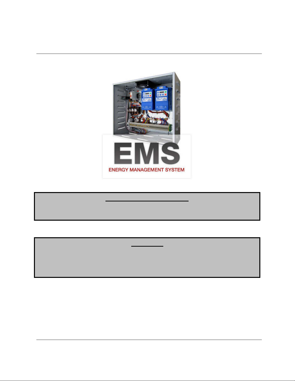
Energy Management System Control
Installation, Operation, and Maintenance Manual
Save these instructions
RECEIVING AND INSPECTION
Upon receiving unit, check for any interior and exterior damage, and if found, report it
WARNING!!
immediately to the carrier. Also check that all accessory items are accounted for and are
damage free.
Installation of this control should only be performed by a qualified professional who has read
and understands these instructions and is familiar with proper safety precautions. Improper
installation poses serious risk of injury due to electric shock, and other potential hazards.
Read this manual thoroughly before installing or servicing this equipment. ALWAYS
disconnect power prior to working on module.
. This document is the property of the owner of this equipment and is
required for future maintenance. Leave this document with the owner when installation or
service is complete.
A0011049
July 2012 Rev. 23
Page 2

TABLE OF CONTENTS
WARRANTY .................................................................................................................................................. 2
INSTALLATION ............................................................................................................................................. 3
Mechanical ................................................................................................................................................ 3
Site Preparation .................................................................................................................................... 3
Assembly .............................................................................................................................................. 3
Utility Cabinet Installation (Typical) ...................................................................................................... 3
Wall Mount Installation (Optional) ........................................................................................................ 3
Duct Sensor Installation ....................................................................................................................... 4
Electrical ................................................................................................................................................... 5
Copper Wire Ampacity ......................................................................................................................... 5
Variable Frequency Drive (VFD) Installation Instructions .................................................................... 6
ACTECH SMV VFD CROSS-REFERENCE TABLE ............................................................................ 7
OPERATION ................................................................................................................................................. 8
Start Up ..................................................................................................................................................... 8
Special Tools Required ........................................................................................................................ 8
Start Up Procedure ............................................................................................................................... 8
Water Wash Option .............................................................................................................................. 9
Loss of Load Relay Option ................................................................................................................... 9
Component Description .......................................................................................................................... 10
Variable Frequency Drive ................................................................................................................... 10
Temperature Control .......................................................................................................................... 11
Temperature Sensor........................................................................................................................... 12
100% Override Timer ......................................................................................................................... 13
Water Wash Timers (Optional) ........................................................................................................... 13
Troubleshooting .................................................................................................................................. 14
MAINTENANCE .......................................................................................................................................... 15
General Maintenance ............................................................................................................................. 15
Every Month ............................................................................................................................................ 15
Enclosure Fan Filter Inspection (Wall Mounted Enclosures Only). .................................................... 15
Start-Up and Maintenance Documentation ............................................................................................ 16
A0011049
July 2012 Rev. 23
Page 3

WARRANTY
This equipment is warranted to be free from defects in materials and workmanship, under normal use and
service, for a period of 12 months from date of shipment. This warranty shall not apply if:
1. The equipment is not installed by a qualified installer per the MANUFACTURER’S installation
instructions shipped with the product,
2. The equipment is not installed in accordance with federal, state and local codes and regulations,
3. The equipment is misused or neglected,
4. The equipment is not operated within its published capacity,
5. The invoice is not paid within the terms of the sales agreement.
The MANUFACTURER shall not be liable for incidental and consequential losses and damages
potentially attributable to malfunctioning equipment. Should any part of the equipment prove to be
defective in material or workmanship within the 12-month warranty period, upon examination by the
MANUFACTURER, such part will be repaired or replaced by MANUFACTURER at no charge. The
BUYER shall pay all labor costs incurred in connection with such repair or replacement. Equipment shall
not be returned without MANUFACTURER’S prior authorization and all returned equipment shall be
shipped by the BUYER, freight prepaid to a destination determined by the MANUFACTURER.
2
A0011049
July 2012 Rev. 23
Page 4
INSTALLATION
It is imperative that this unit is installed and operated with the designed airflow and electrical supply in
accordance with this manual. If there are any questions about any items, please call the service
department at 1-866-784-6900 for warranty and technical support issues.
Mechanical
WARNING: DO NOT LIFT CONTROL BY WIRING COMPONENTS
Site Preparation
1. Provide clearance around installation site to safely install equipment into its final position.
Supports must adequately support equipment. Refer to manufacturer’s estimated weights.
2. Consider general service and installation space when locating unit.
Assembly
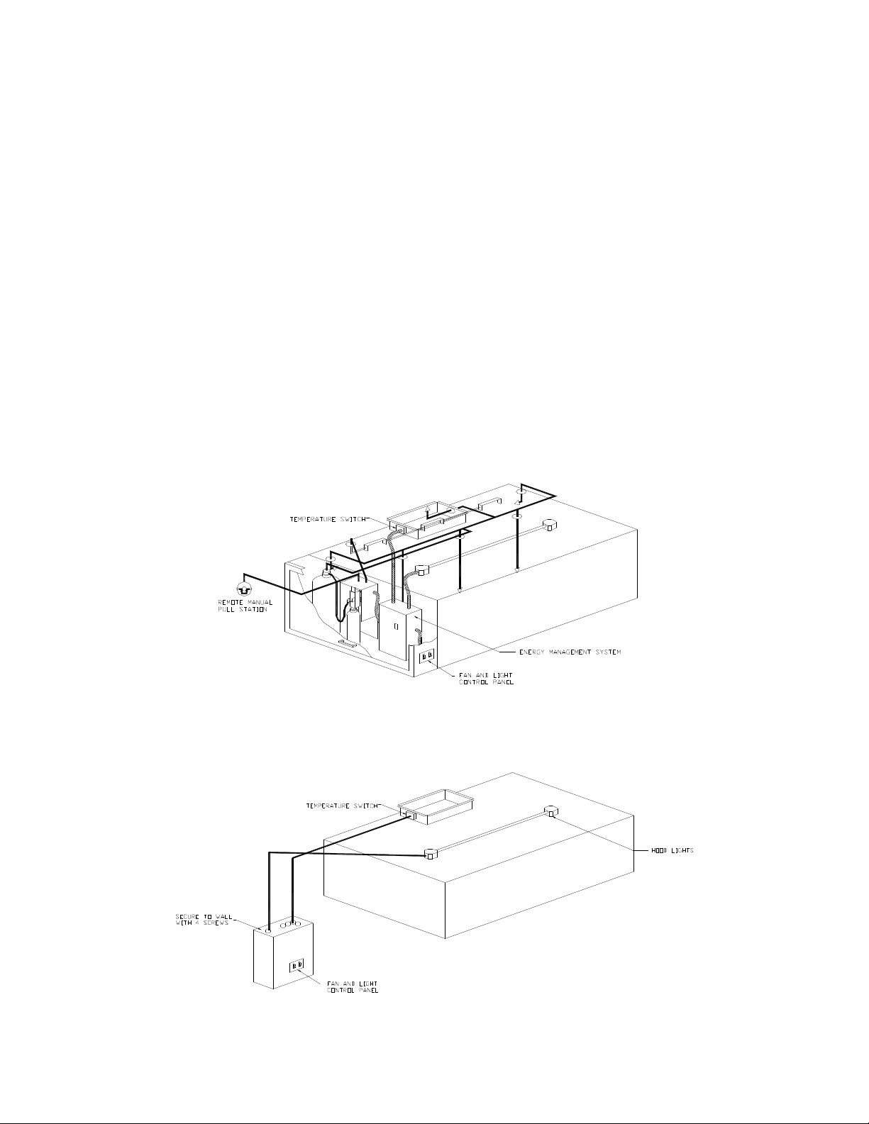
When the energy management system is ordered in a utility cabinet installed on the hood, there is no
mechanical assembly required by the installer. If the energy management system is ordered as a wall
mount configuration, the enclosure must be secured to a fixed wall near the exhaust hoods.
Utility Cabinet Installation (Typical)
Wall Mount Installation (Optional)
3
A0011049
July 2012 Rev. 23
Page 5
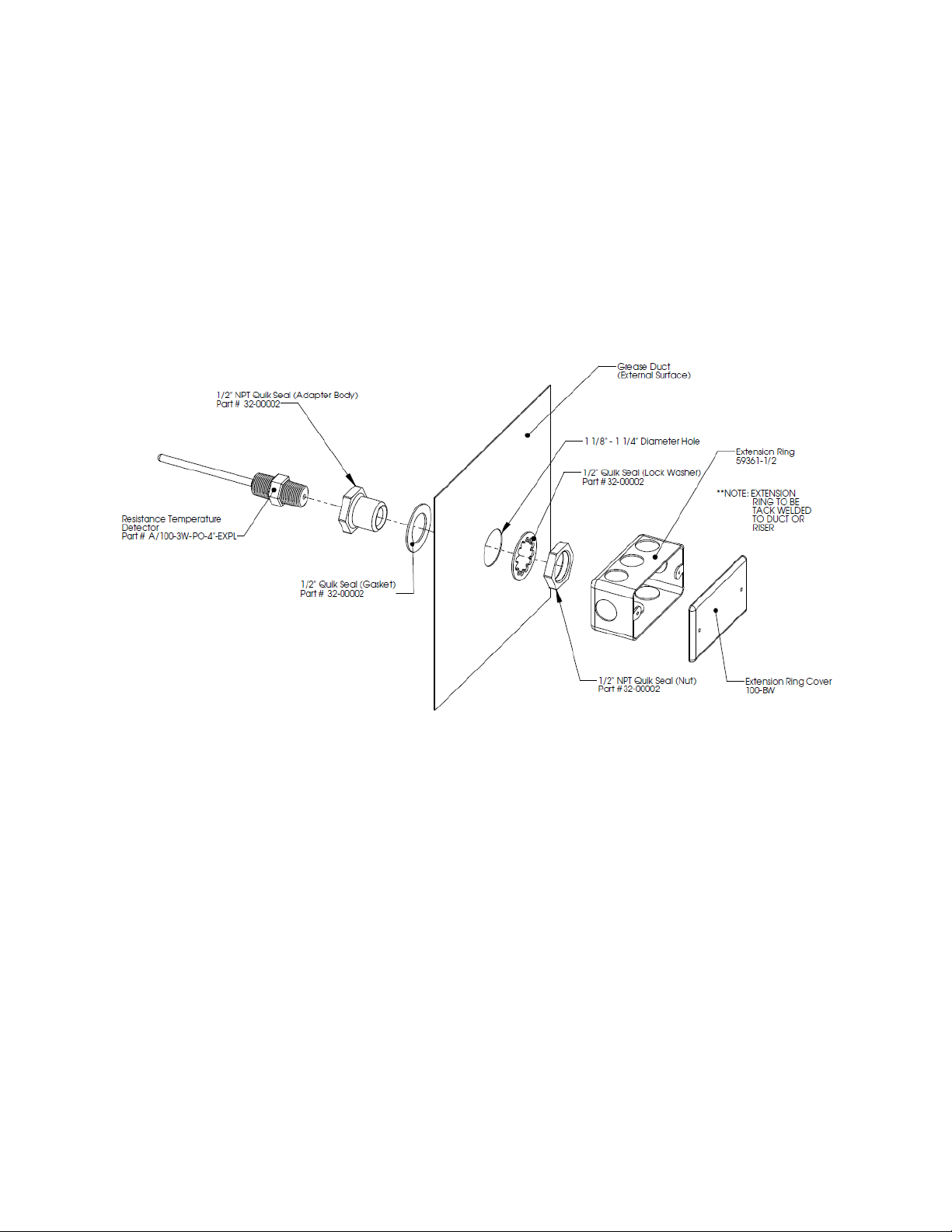
Duct Sensor Installation
When a modulating energy management system is ordered, the system consists of one duct sensor per
fan. If there are multiple risers connected to a single fan, the sensor must be installed where the ducts
come together before the fan unless an EMS with “Multi-Stat” is used. In that case, one sensor is
installed in every riser. These sensors are shipped factory installed in factory assembled hood risers if
there is one riser per fan. If the risers are field cut or the sensor needs to be installed at the junction of
the ducts, the sensor and other components are shipped loose for field installation as shown below. A
hole must be cut in the grease duct and the quick seal and sensor must be assembled as shown. The
sensor has a built in junction box that wires can be run through conduit and attached to.
4
A0011049
July 2012 Rev. 23
Page 6
Electrical
WARNING!!
IMPORTANT!!
Before connecting power to the control, read and understand
the entire section of this document. As-built wiring diagrams
are furnished with each control by the factory, and are attached
either to the door of the unit or provided with a paperwork
packet.
Electrical wiring and connections should be done in
accordance with local ordinances and the National Electric
Code, ANSI/NFPA70. Be sure the voltage and phase of the
power supply and the wire amperage capacity is in accordance
with the unit nameplate.
Disconnect power before
installing or servicing control.
High voltage electrical input is
needed for this equipment. This
work should be performed by a
qualified electrician.
1. Always disconnect power before working on or near
this equipment. Lock and tag the disconnect switch or
breaker to prevent accidental power up.
2. There are multiple electrical connections required
for this control. 120VAC should be wired to terminals
H1 and N1. Input power to the variable frequency
drives should be wired to “L” series terminals. Drive
input power should match the nameplate on the drive.
Output power from the variable frequency drives is
always 3 phase and should match the voltage
requirements of the fan motors. The output power from the drive should be connected to “T”
series terminals.
3. Make certain that the power source is compatible with the requirements of your equipment. The
energy management system wiring schematic identifies the proper phase and voltage of the
equipment.
4. Before connecting control to power source, verify power line wiring is de-energized.
5. Secure the power cable to prevent contact with sharp objects.
6. Do not kink power cable and never allow the cable to come in contact with oil, grease, hot
surfaces or chemicals.
7. If the control is a wall-mount system, the duct mounted temperature sensor will need to be wired
in. The temperature sensor should be wired to terminal blocks as indicated on the wiring
schematic. The hood lights wiring will also need to be wired to terminals “B” and “W”. The fire
system micro-switch will need to be wired to terminals “C1”, “AR1”, and “TR1”. C1 is the
common, AR1 is the armed state, and TR1 is the triggered state. Verify connections on wiring
schematic.
8. Multi-strand thermostat wire must be used to wire the duct temperature sensors back to the main
panel.
9. Before powering up the system, make sure that the interior of the control is free of loose debris or
shipping materials.
10. If motors are spinning in the incorrect direction, switch any two wires on the output of the
variable frequency drive.
11. If any of the original wire supplied with the system must be replaced, it must be replaced with type
THHN wire or equivalent.
Copper Wire Ampacity
Wire Size AWG Maximum Amps
14 15
12 20
10 30
8 50
6 65
4 85
When exhaust duct connections are located and cut in the field, duct temperature probes are
shipped loose in the electrical package enclosure. These must be installed in the duct
immediately above the hood for proper system operation.
5
A0011049
July 2012 Rev. 23
Page 7

Variable Frequency Drive (VFD) Installation Instructions
Input AC Power
1. Circuit breakers feeding the VFDs are recommended to be thermal-magnetic and fast acting.
They should be sized as 1.5 times the input amperage of the drive. Refer to the table below.
2. Each VFD should be fed by its own breaker. If multiple VFDs are to be combined on the same
breaker, each drive should have its own protection measure (fuses or miniature circuit breaker)
downstream from the breaker.
3. Input AC line wires should be run in conduit from the breaker panel to the drives. AC input power
to multiple VFDs can be run in a single conduit if needed.
4. The VFD should be grounded on the terminal marked PE.
STOP!
DO NOT connect incoming AC power to output terminals T1, T2, T3. Severe damage to the
drive will result.
Output Power
1. Motor wires from each VFD to its respective motor MUST be run in a separate steel conduit away
from control wiring and incoming AC power wiring to avoid noise and crosstalk between drives.
2. If the distance between the VFD and the motor exceeds 300 FT, an output reactor should be
used between the VFD and the motor. The output reactor should be sized accordingly.
3. If the distance between the VFD and the motor is between 500 and 1000 FT, a dV/dT filter should
be used.
4. No contactor should be installed between the drive and the motor. Operating such a device while
the drive is running can potentially cause damage to the power components of the drive.
5. When a disconnect switch is installed between the drive and motor, it should only be operated
when the drive is in a STOP state.
Programming
1. The Drive should be programmed for the proper motor voltage. Refer to parameter P107 in the
“Component Description - Variable Frequency Drive” chapter below.
P107 is set to 0 (Low) if motor voltage is 120 VAC, 208 VAC or 400 VAC. P107 is set to 1 (High)
if motor voltage is 230 VAC, 480 VAC or 575 VAC.
2. The Drive should be programmed for the proper motor overload value. Refer to parameter P108
in the “Component Description - Variable Frequency Drive” chapter below.
P108 is calculated as Motor FLA x 100 / Drive Output Rating (available in table below).
6
A0011049
July 2012 Rev. 23
Page 8

ACTECH SMV VFD CROSS-REFERENCE TABLE
Input
Input
Input
input
M/N Volts
1Ø
input
3Ø
input HP
Amps
1Ø
120VAC
Amps
1Ø
240VAC
Output
Amps KVA
Breaker
1Ø
120VAC
Breaker
1Ø
240VAC
120/
ESV251N01SXB531
240V X 0.33
6.8 3.4 1.7 0.816 15 15
120/
ESV371N01SXB531
240V X 0.5 9.2 4.6 2.4 1.104 15 15
120/
ESV751N01SXB531
240V X 1 16.6 8.3 4.2 1.992 25 15
120/
ESV112N01SXB531
240V X 1.5 20 10 6 2.4 30 20
Amps
1Ø
Amps
3Ø
Breaker
1Ø
Breaker
3Ø
ESV371N02YXB531 240V X X 0.5 5.1 2.9 2.4 1.20 15 15
ESV751N02YXB531 240V X X 1 8.8 5 4.2 2.08 15 15
ESV112N02YXB531 240V X X 1.5 12 6.9 6 2.86 20 15
ESV152N02YXB531 240V X X 2 13.3 8.1 7 3.36 25 15
ESV222N02YXB531 240V X X 3 17.1 10.8 9.6 4.48 30 20
ESV402N02TXB531 240V X 5 18.6 16.5 7.72 30
ESV552N02TXB531 240V X 7.5 26 23 10.80 40
ESV752N02TXB531 240V X 10 33 29 13.70 50
ESV113N02TXB531 240V X 15 48 42 19.93 80
ESV153N02TXB531 240V X 20 59 54 24.50 90
ESV751N04TXB531 480V X 1 2.5 2.1 2.08 15
ESV112N04TXB531 480V X 1.5 3.6 3 2.99 15
ESV152N04TXB531 480V X 2 4.1 3.5 3.40 15
ESV222N04TXB531 480V X 3 5.4 4.8 4.48 15
ESV402N04TXB531 480V X 5 9.3 8.2 7.72 15
ESV552N04TXB531 480V X 7.5 12.4 11 10.30 20
ESV752N04TXB531 480V X 10 15.8 14 13.12 25
ESV113N04TXB531 480V X 15 24 21 19.93 40
ESV153N04TXB531 480V X 20 31 27 25.74 50
ESV183N04TXB531 480V X 25 38 34 31.56 60
ESV223N04TXB531 480V X 30 45 40 37.37 70
ESV751N06TXB531 600V X 1 2 1.7 2.08 15
ESV152N06TXB531 600V X 2 3.2 2.7 3.32 15
ESV222N06TXB531 600V X 3 4.4 3.9 4.57 15
ESV402N06TXB531 600V X 5 6.8 6.1 7.06 15
ESV552N06TXB531 600V X 7.5 10.2 9 10.59 20
ESV752N06TXB531 600V X 10 12.4 11 12.87 20
ESV113N06TXB531 600V X 15 19.7 17 20.45 30
ESV153N06TXB531 600V X 20 25 22 25.95 40
ESV183N06TXB531 600V X 25 31 27 32.18 50
ESV223N06TXB531 600V X 30 36 32 37.37 60
7
A0011049
July 2012 Rev. 23
Page 9

OPERATION
Prior to starting up or operating the energy management system, check all fasteners and wires for
tightness. The VFDs (variable frequency drives) included in this system have been factory programmed
at 60Hz for high speed and 48Hz for low speed. This results in a 20% reduction in airflow when operation
is in low speed. The VFDs are used to adjust the speed of 3 phase motors and frequency is directly
proportional to airflow.
Start Up
Special Tools Required
• AC Voltage Meter
• Amperage Meter
• Standard Hand Tools
Start Up Procedure
1. Once all power, lights, and temperature
sensor(s) are connected and the fans are
operating in the correct direction, startup
can begin. The “Power” light should be
illuminated. If the light does not illuminate,
there is not 120V incoming power into the
panel.
2. Press the “Lights On” switch to energize
the hood lights. If the lights do not come
on, install light bulbs or check the lighting
circuit.
3. Press the “Fans On” switch to energize the
VFDs and fans. The fans take a few
seconds to come up to speed. The VFDs
should all indicate 48Hz and the “Fans On”
indicator light should illuminate. This
indicates that the fans are operating on low
speed. If the supply fan drive does not power up, the fire system micro-switch is not in the armed
position or has not been connected properly. A fire system distributor should service the microswitch or arm the fire system.
4. Press the “100% Airflow” button on the control interface. The “100% Airflow Override” indicator
light should illuminate and all of the VFDs should indicate 60Hz or high speed. This indicates
that the fans are operation on high speed. The fans should stay at this speed for a factory set
time of 30 minutes. This time is adjustable as described in the timer component section. After
the time interval expires, the drives should return to 48Hz or low speed. The high speed and low
speed frequencies are adjustable as described in the VFD component section.
5. Turn on the cooking appliance and allow it to reach idle temperature. If the fan switch is in the
“OFF” position, the fans should automatically be energized as the cooking appliance heats up.
The low temperature set point in the temperature control should be set to approximately 5
degrees above kitchen ambient temperature. If this value must be changed, there are other
values that must be changed as well. See the temperature control component section for further
details.
6. The appliances running in idle mode should not make the energy management system
operate at high speed. The fans should modulate during the cooking process.
7. If the fans go to high speed while the cooking appliances are idling, the high temperature set
point should be adjusted. Increase the high temperature set point. If this value must be
changed, there are other values that must be changed as well. See the temperature control
component section for further details.
Operation Chart
8
A0011049
July 2012 Rev. 23
Page 10

8. If the fans never or rarely go to high speed while cooking is taking place, the high temperature
set point should be adjusted. Decrease the high temperature set point. If this value must be
changed, there are other values that must be changed as well. See the temperature control
component section for further details.
9. Start-up is complete.
Water Wash Option
1. If the control contains the water wash option, there are 2 timers that control the water wash spray
and the surfactant injection. The wash timer is a fleeting off timer and is set to 3 minutes from the
factory. The surfactant timer is an asynchronous timer that is factory set for 1 second of injection
with a 1 minute off time. The injection occurs at the start of each minute.
2. To operate the wash cycle, simply turn the fan switch on and then back off. The wash cycle
energizes automatically.
3. After the time expires that is on the wash timer, the cycle ends.
4. Hood filters MUST remain in place during the wash cycle.
Loss of Load Relay Option
1. If the control contains the loss of load relay functionality for supply-exhaust interlocks, this must
be configured in the field after a test and balance has been performed on the fans. When this
option is selected, the supply fan must prove airflow first, followed by the exhaust fan. Once the
exhaust fan airflow is proven, the supply fan burner can be ignited if equipped.
2. Parameter P145 on the drive controls this functionality. P145 is configured for loss of power load
on the drive. P145 sets the percentage of nameplate amperage that would be considered a loss
of load. For example, if nameplate VFD amperage is 10 amps and P145 is set to 60%, then a
loss of load condition would occur if the fan motor amperage drops below 6 amps.
3. To set this value properly, the fans must be run in their low speed condition. (15 Hz for self
cleaning hoods and 48 Hz for non self cleaning applications). While the fans are operating at low
speed, the fan amperage must be measured. This is the percentage of nameplate amperage that
must be entered into P145.
4. This value may need to be adjusted down a few percentage points to prevent nuisance trips.
5. To test this system, remove the belts from either the supply fan or the exhaust fan to simulate a
loss of airflow. The system should shut all fans down within 10 seconds.
9
A0011049
July 2012 Rev. 23
Page 11

10
Component Description
Variable Frequency Drive
Variable frequency drives change the speed of 3 phase motors by changing the
frequency signal sent to the motor. There is one variable frequency drive for each fan
in this system. The drives are factory set to operate at 60Hz on high speed and 48Hz
on low speed. This difference in speed produces a 20% CFM reduction on low speed.
In some applications, and for test and balance reasons, the high and low speeds will
need to be adjusted.
Variable Frequency Drive Parameters
Variable frequency drive parameters can be changed with the buttons on the face of the drive. Only
parameters P103, P132, P133, P136, P140, P144, P152, P160 and P161 should be manipulated. To
enter the PROGRAM mode to access the parameters:
1. Press the Mode (M) button. This will activate the password prompt (PASS).
2. Use the Up and Down buttons to scroll to the password value (the factory default password is
“0225”) and press the Mode (M) button. Once the correct password is entered, the display will
read “P100”, which indicates that the PROGRAM mode has been accessed at the beginning of
the parameter menu.
3. Use the Up and Down buttons to scroll to the desired parameter number (for example, parameter
160).
4. Once the desired parameter is found, press the Mode (M) button to display the present parameter
setting. The parameter value will begin blinking, indicating that the present parameter setting is
being displayed. The value of the parameter can be changed by using the Up and Down buttons.
5. Pressing the Mode (M) button will store the new setting and also exit the PROGRAM mode. To
change another parameter, press the Mode (M) button again to re-enter the PROGRAM mode. If
the Mode button is pressed within 1 minute of exiting the PROGRAM mode, the password is not
required to access the parameters. After one minute, the password must be entered in order to
access the parameters again.
The high speed frequency should only be adjusted to achieve design airflow rates or to fix exhaust
problems while cooking is taking place. Each time the high speed frequency is adjusted, the low speed(s)
should also be adjusted. The manufacturer suggests a 20% airflow reduction. For example, if the high
speed frequency is set at 50 Hz, then low speed should be set at 40 Hz (50*0.8). All supply and exhaust
drives should be adjusted to the same values.
Parameter P103, P133, P136 and P161 on the drives control the high speed frequency. All of these
parameters must be set to the same value.
Parameter P152 is related to the high speed frequency and is a scaling factor. For a supply fan drive, this
parameter should be set to the same value as the group above. For an exhaust fan drive, this value
should be set to the high speed frequency times the number of exhaust fans. For example, if the high
speed frequency is 35 Hz and there are 2 exhaust drives, this parameter should be set to 70 Hz.
Parameter P160 on the exhaust drive controls the low speed exhaust frequency. This should be set to
20% less than the high speed frequency.
Parameter P132 on the exhaust fan drives is set to 15 Hz for the water wash option. This will keep the
hoods running at a low speed during the wash cycle. This prevents water from escaping through the
hood filters. This should be adjusted as needed to prevent water from exiting hood.
Examples of exhaust and supply VFD parameters are shown in the tables above. To reverse motor
rotation, any 2 legs of the output of the drive should be switched.
A0011049
July 2012 Rev. 23
Page 12

11
Temperature Control
There is a digital temperature control shipped with these systems. There is
one control for every exhaust fan being controlled by the EMS. The temp
control is multi-functional and includes input from the duct mounted RTD,
relay contacts driven by programmable alarms, and a signal output to speed
up and slow down the VFDs.
There are two factory set ranges of temperature controls. The low temp range is factory programmed for
400-450°F rated hoods. It is pre-programmed to tur n the fans on automatically at 85°F and to send the
fans to high speed at a 90°F duct temperature. The high temp range is factory programmed for 600700°F rated hoods. It is pre-programmed to turn th e fans on automatically at 85°F and to send the fan s to
high speed at a 130°F duct temperature.
It is the manufacturer’s recommendation that the low temp set point (factory
set at 85°F) be set to 5°F above the kitchen ambien t temperature. Settings
less then 5°F above ambient can cause the fans to s tay operating for hours
after the cooking appliances have been turned off. Settings of more then 5°F
above kitchen ambient can cause the fans to cycle on and off many times
after the cooking appliances have been turned off. When this value needs to
be changed, parameters A1-H and SV-L must all be set to the new value. P
must be changed as well as discussed below.
The high temp set point must be fine tuned to the application. A setting of
90°F will work well for ovens and griddles, while 1 30 will work well for charbroilers. There may be situations where a combination of these appliances or
different appliances are used and the high temp set point will need to be
changed. When this value needs to be changed, parameters AL2 and SV-H
must all be set to the new value. P must be changed as well as discussed
below.
If either the low temp set point or the high temp set point require a change, the
ramping parameter “P” will need to be changed as well. This value relates
those two set points and drives the VFD. Use the following formula to
calculate P.
P = 100 * (AL2-A1-H)/200
Low Temp Control
Parameter Factory Setting
SV 85
LEVEL 1
A1-H 85
AL2 90
LEVEL 2
P 2.5
LEVEL 3
SV-L 85
SV-H 90
High Temp Control
SV 85
LEVEL 1
A1-H 85
AL2 130
LEVEL 2
P 22.5
LEVEL 3
SV-L 85
SV-H 130
The default display of the temperature control is PV (process value). To
modify all other parameters, follow these instructions:
1. To change the SV (set value), simply use the up and down arrow
buttons. The SV must match A1-H.
2. To modify the level 1 parameters, press and hold the “SEL” button for
approximately 1 second. This will bring up the A1-H parameter.
Momentarily press the “SEL” button to bring up the value of that
parameter. Use the Up and Down buttons to modify the value. Once
Parameter Definitions
PV Process Value
SV Set Value
A1-H Alarm 1 Set Value
AL2 Alarm 2 Set Value
P Proportional Band
SV-L Set Value Lower Limit
SV-H Set Value Upper Limit
SV-H 130
the desired value is found, press the “SEL” button once more.
3. Press the Up or Down button to move to the next parameter. Only
A1-H and AL2 are located in the level 1 parameters.
4. To move to Level 2 parameters, press and hold the “SEL” button for approximately 3 seconds.
This will allow access to P. P should be calculated based on AL2 and A1-H.
5. To move to the Level 3 parameters, press and hold the “SEL” button for approximately 5
seconds. This will allow access to SV-L and SV-H. SV-L and SV-H are the upper and lower
limits of SV.
A0011049
July 2012 Rev. 23
Page 13

12
Temperature Control Names and Functions
Temperature Sensor
The temperature sensor used in modulating systems is a digital RTD (Resistance Temperature Detector).
The sensor gives constant feedback to the temperate control. There is usually one sensor per exhaust
fan. If multiple hood risers are connected to one fan, this sensor must be installed where the two ducts
converge and prior to the fan.
If an EMS with “Multi-Stat” is used, one sensor is installed in every riser. The maximum value of all
sensors associated with one exhaust fan is used to modulate that fan.
A0011049
July 2012 Rev. 23
Page 14
13
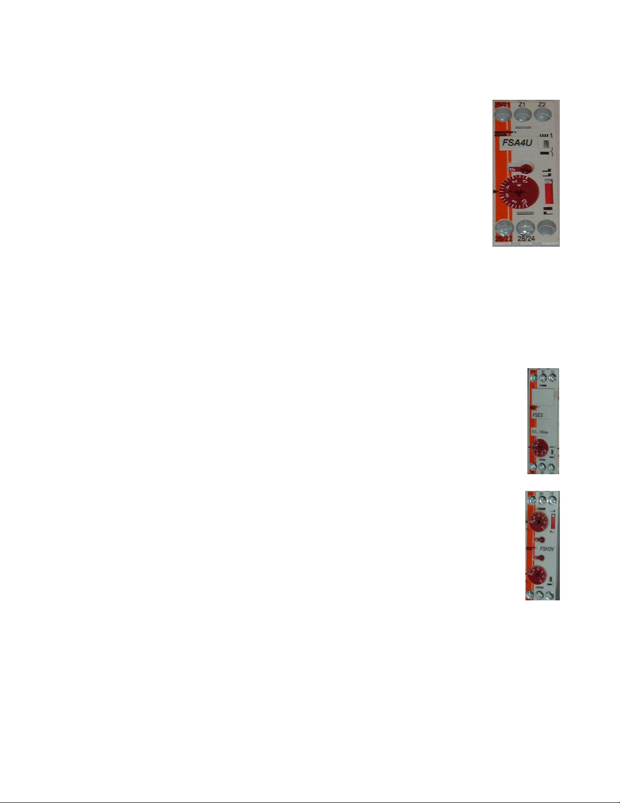
100% Override Timer
The timer included in this package is energized when the “100% Airflow” button is
depressed. The timer holds the fan speed on high for a set amount of time. Once the time
period expires, the fans operate based on the duct temperature switch. This time period is
factory set at 30 minutes, but is adjustable on an application specific basis. The time
range adjustment is from .05 seconds to 60 hours. The small top dial on the timer allows
main unit adjustments. This dial can be set to 1, 3, 10, or 60 seconds(s), minutes(m), or
hours(h). Once the small top dial is set, the large red dial adjusts the percentage of the
middle dial. For example, if the small top dial is set to 1 hr, and the large red dial is set to
.25, the selected time period would result in 15 (1 hr * .25 = 15 minutes) minutes. The large
dial is a percentage of the small dial. The red switch on the right side of the face of the
timer should NOT be adjusted and is factory set to the bottom position (on delay).
Water Wash Timers (Optional)
The water wash option includes two timers that ship in the main control panel. These timers control the
wash cycle length and the surfactant injection.
The timer shown to the right is the wash cycle timer. The wash cycle timer is a fleeting off timer and is
triggered by turning the fan switch to the “OFF” position. The time is factory set to 3 minutes but is
adjustable on an application specific basis. It has a range of .5 to 10 minutes and is adjusted by simply
rotating the large red dial.
The time shown on the right is the surfactant injection timer. The surfactant timer is a
asynchronous on-off timer. This means that it cycles contacts on and off for adjustable time
ranges. The timer is factory set to inject surfactant for 1 second and every minute. The interval
time (time when not injecting) is set by the top two dials. The small top dial on the timer allows
main unit adjustments. This dial can be set to 1, 3, 10, or 60 seconds(s), minutes(m), or hours(h).
Once the small top dial is set, the top, large red dial adjusts the percentage of the middle dial. For
example, if the small top dial is set to 1 minute, and the large red dial is set to 1.0, the selected time
period would result in 1 (1 minute * 1.0 = 1 minute) minute. The large dial is a percentage of the
small dial.
The surfactant injection time is set by the bottom two dials. The small bottom dial on the timer
allows main unit adjustments. This dial can be set to 1, 3, 10, or 60 seconds(s), minutes(m), or
hours(h). Once the small bottom dial is set, the bottom, large red dial adjusts the percentage of
the middle dial. For example, if the small bottom dial is set to 1 second, and the large red dial is
set to 1.0, the selected time period would result in 1 (1 second * 1.0 = 1 second) second. The
large dial is a percentage of the small dial.
The red switch on the right side of the face of the timer should NOT be adjusted and is
factory set to the bottom position (beginning of time period).
A0011049
July 2012 Rev. 23
Page 15

14
Troubleshooting
Smoke Rollout of Hood
Smoke Rollout of Hood
Fans Never Go to High
Decrease
Fans Never Go to Low
Fans Spin Wrong
Exhaust Fan
On and
Power Light Not On
100% Override Button
Fan Switch On but No
Light Switch On but No
Water Wash Cycle
Water
Wash Hood not
The following table lists causes and corrective actions for possible problems with this control. Review this
list prior to consulting manufacturer.
Troubleshooting Chart
Problem
at High Speed or 100%
Operation
at Low Speed Operation
Speed
Speed
Direction
Supply Fan will not
Start
Does Not Increase
Exhaust
Fans Come On
Lights Come On
Never Runs
staying clean
Potential Cause
High speed set too low Increase exhaust and supply fan variable
Improper hood installation Check for proper hood overhang, cross drafts or
Low Speed set too low Increase exhaust and supply fan variable
Improper hood installation Check for proper hood overhang, cross drafts or
Dirty temperature sensor Clean grease and dirt from sensor
High Set Point on Temperature
Control Set Too High
Low Temperature set point on
temperature control set too high
VFD Output wiring incorrect Switch any two leads on the output of the VFDs
Broken supply fan belt Replace fan belt
Fire system not armed Fire system distributor must arm fire system
No power into enclosure Check main 120V power supply
Exhaust already at 100% Proper operation
Loose wiring connection Check override button, timer, and terminal block
Broken fan belt Replace fan belt
Variable frequency drive error Clear error on variable frequency drive. Refer to
Loose wiring connection Check fan switch and terminal block wiring
Light bulbs are blown Replace hood light bulbs
Loose wiring connection Check light switch and light terminal block wiring
Improperly set Wash Timer
(Water Wash Systems Only)
Surfactant Not Being Injected Asynchronous surfactant timer set incorrectly.
Wash time not set high enough Increase Wash time
Surfactant container Empty Replace Surfactant Container
Corrective Action
frequency drive high speed set points
improper hood design
frequency drive low speed set points
improper hood design
high temperature set point on
temperature control. This will force the fans to
high speed at a lower exhaust temperature.
Reduce low temp set point on temperature
control by 2 degrees. This will allow cooking
equipment to further cool and prevent cycling.
Repeat this step until satisfied.
wiring connections
drive manual.
connections
connections
Fleeting Off Timer should be set to a value
greater then 0. LED on face of timer should blink
while in wash cycle.
Increase injection time or decrease pause time.
A0011049
July 2012 Rev. 23
Page 16

15
MAINTENANCE
To guarantee trouble free operation of this control, the manufacturer suggests following these guidelines.
Most problems associated with unit failures are directly related to poor service and maintenance.
Please record any maintenance or service performed on this equipment in the documentation section
located at the end of this manual.
WARNING: DO NOT ATTEMPT MAINTENANCE ON THIS CONTROL UNTIL THE
ELECTRICAL SUPPLY HAS BEEN COMPLETELY DISCONNECTED
General Maintenance
1. Control enclosure should be kept clean and free from any grease or dirt build-up.
2. All fasteners should be checked for tightness each time maintenance checks are preformed prior
to restarting unit.
3. Control enclosure door panel should be securely closed after maintenance to prevent tampering
or electrical shock.
Every Month
1. Temperature sensor(s) in exhaust hood riser(s) need to be cleaned by wiping any grease or
dust build-up from probe with a clean cloth. A clean sensor ensures that the temperature switch
will quickly respond to changes in exhaust air temperature.
2. Check all fasteners, sensors, and electrical connections for proper tightness and continuity.
Enclosure Fan Filter Inspection (Wall Mounted Enclosures Only).
1. Remove outer black plastic housing of the enclosure fan to gain access to the fan filter.
The cover is held in place by frictional clips, simply pry on it to remove.
2. Inspect the fan filter for grease/debris. If the filter is dirty, clean or replace.
Replacement fan filter part number: MC32658 (pack of 5)
WARNING: If fan filter cleaning is not performed, grease/debris buildup
may occur resulting in VFD failure due to overheating. VFD warranty may
be denied if filter inspection is not performed on a monthly basis and
logged on the maintenance record.
A0011049
July 2012 Rev. 23
Page 17

16
Start-Up and Maintenance Documentation
°F
START-UP AND MEASUREMENTS SHOULD BE PERFORMED AFTER THE SYSTEM HAS BEEN
AIR BALANCED (Warranty will be void without completion of this form)
Job Information
Job Name Service Company
Address Address
City City
State State
Zip Zip
Phone Number Phone Number
Fax Number Fax Number
Contact Contact
Purchase Date Start-Up Date
Energy Management System Information
Refer to the start-up procedure in this manual to complete this section.
Name Plate and Unit Information
Model Number
Serial Number
Volts
Hertz
Phase
Field Measured Information
Voltage
Thermostat Set-Point(s)
Timer Set-Points
Blower/Fan Rotation Correct
Incorrect
Maintenance Record
Date Service Performed
Factory Service Department
Phone: 1-866-784-6900
Fax: 1-919-554-9374
A0011049
July 2012 Rev. 23
 Loading...