

Page 1

RM7890A,B,C/EC7890A,B
7800 SERIES Relay Modules
INSTALLATION INSTRUCTIONS
APPLICATION
The Honeywell RM78 90A,B,C/EC7890A ,B Relay Mod ules are
microprocessor based integrated burner controls for
semi-automatically fired gas, oil, or combination fuel single
burner applications. The RM/EC7 890 Rel ay Mo dul e is
intended to replace the RA890F,G, H Protectorelay® Primary
Control. The RM/EC7890 System consists of a relay module,
subbase, and amplifier. Options include Personal Computer
Interface, keyboard display module (KDM), Data ControlBus
Module™, remote display mounting, first-out expanded
annunciator and Combustion System Manager¨ Software.
Functions the RM/EC7890 provides include automatic burner
sequencing, flame supervision, system status indication,
system or self-diagnostics and troubleshooting.
This document provides installation and static checkout
instructions. Other applicable publications are:
63-2278: Q7700 Network Interface Unit.
65-0084: Q7800A,B 22-Terminal Wiring Subbase Product
Data.
65-0090: S7800A Keyboard Display Module Product Data.
65-0091: S7810A Data ControlBus Module™ Product Data.
65-0095: S7820 Remote Reset Module Product Data.
65-0097: 221729C Dust Cover Packing Instructions.
65-0101: S7830 Expanded Annunciator Product Data.
65-0109: R7824, R7847, R7848, R7849, R7861, R7886
Flame Amplifiers for the 7800 SERIES Product Data.
65-0131: 221818A Extension Cable Assembly Product Data.
65-0229: 7800 SERIES Relay Modules Checkout and
Troubleshooting.
SPECIFICATIONS
Electrical Ratings (See Table 3):
Volta ge and Frequency:
RM7890: 120 Vac (+10/-15%), 50/60 Hz (±10%).
EC7890: 220/ 240 Vac (+10%/-15%), 50/60 Hz (±10%).
Power Dissipation: 10W maximum.
Maximum Total Connected Load: 2000 VA.
Fusing Total Connected Load: 2 0A max imum , type FRN or
equivalent.
Environmental Ratings:
Ambient Temperature:
Operating: -40°F to +140°F (-40°C to +60°C).
Storage: -40°F to +150°F (-40°C to +66°C).
Humidity: 85% relative humidity continuous, noncondensing.
Vibration: 0.5G environment.
Approvals:
RM7890A,B:
Underwriters Laboratories Inc. Listed: File No. MP268,
Guide No. MCCZ.
Canadian Standards Association Certified: LR9S329-3.
Factory Mutual Approved: Report No. J.I.1V9A0.AF.
Industrial Risk Insurers: Acceptable.
Federal Communications Commission: Part 15, Class B,
Emissions.
RM7890C:
Underwriters Laboratories Inc.: Component Recognized.
EC7890:
Factory Mutual: Approved.
® U.S. Registered Trademark
Copyright © 2000 Honeywell • All Rights Reserved
66- 1089-3
Page 2

RM7890A,B,C/EC7890A,B 7800 SERIES RELAY MODULES
INSTALLATION
WARNING
Fire or Explosion Hazard.
Can cause property damage, serious injury, or
death.
T o preven t possible hazardous bur ner operation, verif y
safety requirements eac h tim e a co ntro l is installed on
a burner.
WARNING
Electrical Shock Hazard.
Can cause personal injury, death or equipment
damage.
Disconnect the power supply before beginning
installation.
When Installing this Product...
1.
Read these instructio ns c aref ull y. Failure to follow them
could damage the product or cause a hazardous
condition.
2.
Check the ratings given in the instructions and marked
on the product to make sure the product is suitable for
the application.
3.
Installer must be a trained, experienced, flame
safeguard service technician.
4.
After installation is complete, check out the product
operation as provided in these instructions.
IMPORTANT
1. Wiring connecti ons for the relay m odules are unique;
refer to Fig. 2 or the appropriate Specifications for
individual subbase wiring.
2. Wiring must comply with all applicable codes,
ordinances and regulations.
3. Wiring must comp ly with N EC Clas s 1 (Line Voltage)
wiring.
4. Loads connected to the RM/EC7890 must not
exceed those listed on the RM/EC7890 label or the
Specifications; see Tables 3, 4, and 5.
5. Limits and interlocks must be rated to simultaneously
carry and break current to the ignition transformer,
pilot valve, and main fuel valve(s).
6. All external timers must be listed or componentrecognized by authorities who have proper
jurisdiction.
7. For on-off gas-fired systems, some authorities who
have jurisdiction prohibit the wiring of any limit or
operating contacts in series between the flame
safeguard control and the main fuel valve(s).
8. Two flame detectors can be connected in parallel
with the exception of Infrared Flame Detectors
(C7015).
9. This equipment generates, uses and can radiate
radio frequency energy and, if not in stall ed and us ed
in accordance with the instructi ons, can caus e
interference with radio communications. It has been
tested and found to com ply with th e lim its for a Class
B computing device of Part 15 of FCC rules which
are designed to provide reasonable protection
against such interference when operated in a
commercial environment. Operation of this
equipment in a residential area can cause
interference, in which case, the users, at their own
expense, may be required to take whatever
measures are required to correct this interference.
10.This digital apparatus does not exceed the Class B
limits for radio noise for digital apparatus set out in
the Radio Interference Regulations of the Canadian
Department of Communica tio ns .
Location
Humidity
Install the relay module where the relative humidity never
reaches the saturation point. The relay module is designed to
operate in a maximum 85% relative humidity continuous,
noncondensing, moisture environment. Condensing moisture
can cause a safety shutdown.
Vibration
Do not install the relay module where it can be subjected to
vibration in excess of 0.5G continuous maximum vibration.
Weather
The relay module is not designed to be weather tight. When
installed outdoors, protect the relay module in an approved
weather-tight enclosure.
Mounting Wiring Subbase
See Fig. 1 for the intern al blo ck dia gram o f RM/EC78 90 Rel ay
Module.
1.
Mount the subbase in any position except horizontally
with the bifurcated contacts pointing down. The
standard vertical position is recommended. Any other
position decreases the maximum ambient temperature
rating.
2.
Select a location on a w all, burner or electrical panel.
The Q7800 can be mounted directly in the control
cabinet. Be sure to allow adequate clearance for
servicing, installation, access or removal of the
RM/EC7890, expanded annunciator, KDM, flame
amplifier, flame amplifier signal voltage probes, run/test
switch, electrical signal voltage probes and electrical
field connections.
3.
For surface mounting, u se the back of t he sub base a s a
template to mark the four screw locations. Drill the pilot
holes.
4.
Securely mount the subbase using four no. 6 screws
(not provided).
66-1089—3 2
Page 3
RM7890A,B,C/EC7890A,B 7800 SERIES RELAY MODULES
Wiring
WARNING
Electrical Shock Hazard.
Can cause personal injury or equipment damage.
Disconnect the power supply before beginning
installation.
1.
For proper subbase wiring and sequence chart, refer to
Fig. 2.
2.
For proper remote wiring of the KDM, refer to the
Specifications for the KDM (65-009 0), Network Interface
Unit (63-2278), Data ControlBus Module™ (65-0091) or
Extension Cable Assembly (65-0 13 1).
3.
Disconnect the power supply from the main disconnect
before beginning installation to prevent electrical shock
and equipment damage . More than one disconnec t can
be required.
4.
All wiring must comply with all applicable electrical
codes, ordinances and regulations. Wiring, where
required, must com ply wi th NEC, Clas s 1 (Li ne Voltage)
wiring.
5.
Use recommended wire routing of leadwires:
a. Do not run high vol tag e ig ni tion transformer wires in
the same conduit with the flame detector, Data
ControlBus Module™, or Remote Reset Module
wiring.
b. Do not route flame detector, Data ControlBus
Module™, or Remote Reset Module leadwires in
conduit with line voltage circuits.
c. Enclose fla me detector leadwires without arm or
cable in metal cable or conduit.
d. Follow directions in flam e detector, Data ControlBus
6.
Module™, or Remote Reset Module Instructions.
For KDM (KDM), because the KDM is powered from a
low voltage, energy limited source, it can be mounted
outside of a control panel if it is protected from
mechanical damage.
NOTE: Use 13 Vdc power supply any time more than one
10.
11.
KDM is used. A maximum of two KDM, Data
ControlBus Modules™ or S7810B Multi-Drop Switch
Modules are allowed in any combination.
7.
Use maximum wire lengths:
a. RM/EC7890 leadwires: The maximum leadwire
length is 300 feet (91 meters) to terminal inputs
(Control, Running/Lock out Interlo ck ).
b. Flame Detector leadwires: The maximum flame
sensor leadwire len gth i s li mi ted by the flam e s ign al
strength.
c. Remote Reset leadwires: The maximum length of
wire is 1000 feet (305 meters) to a Remote Reset
pushbutton.
d. Data ControlBus Module™: The maximum Data
ControlBus Module™ cable length depends on the
number of system modules connected, the noise
conditions and the c able used. The maximum l ength
of all Data ControlBus Module™ interconnecting
8.
9.
wire is 4000 feet (1219 meters).
For recommended wire size and type, see Table 1.
The KDM, Data ControlBus Module™ (for remote
mounting or communications) or Communication
Interface ControlBus™ Modu le m ust b e wired in a dais y
chain configuration,
1(a)-1(a), 2(b)-2(b), 3(c)-3(c). The order of
interconnection of all the devices listed above is not
important. Be aware that modules on the closest and
farthest end of the daisy chain configuration string
require a 120 ohm (1/4 watt minimum) resistor
termination across terminals 1 and 2 of the electrical
connectors for connections over 100 feet (31 meters).
For recommended grounding practices, see Table 2.
Be sure loads do not exceed the te rmi nal ratin gs . Refer
to the label on the RM/EC7890 or to the terminal ratings
in Table 3.
Table 1. Recommended Wire Sizes and Part Numbers.
Application Recommended Wire Size Recommended Part Numbers
Line voltage terminals 14, 16, or 18 AWG copper conductor, 600
volt insulation wire.
Keyboard Display Module 22 AWG two-wire twisted pair with ground,
Data ControlBus Module™ 22 AWG two-wire twisted pair with ground,
Remote Reset Module 22 AWG two-wire twisted pair, insulated for
Communications Interf ace C ontro lBus™
Module
13 Vdc full-wave rectified transformer
power input.
or five-wire.
or five-wire.
low voltage.
22 AWG two-wire twisted pair with ground. Belden 8723 shielded cable or
18 AWG wire insulated for voltages and
temperatures for given application.
3 66-1089—3
TTW60C, THW75C, THHN90C.
Belden 8723 shielded cable or
equivalent.
Belden 8723 shielded cable or
equivalent.
—
equivalent.
TTW60C, THW75C, THHN90C.
Page 4
RM7890A,B,C/EC7890A,B 7800 SERIES RELAY MODULES
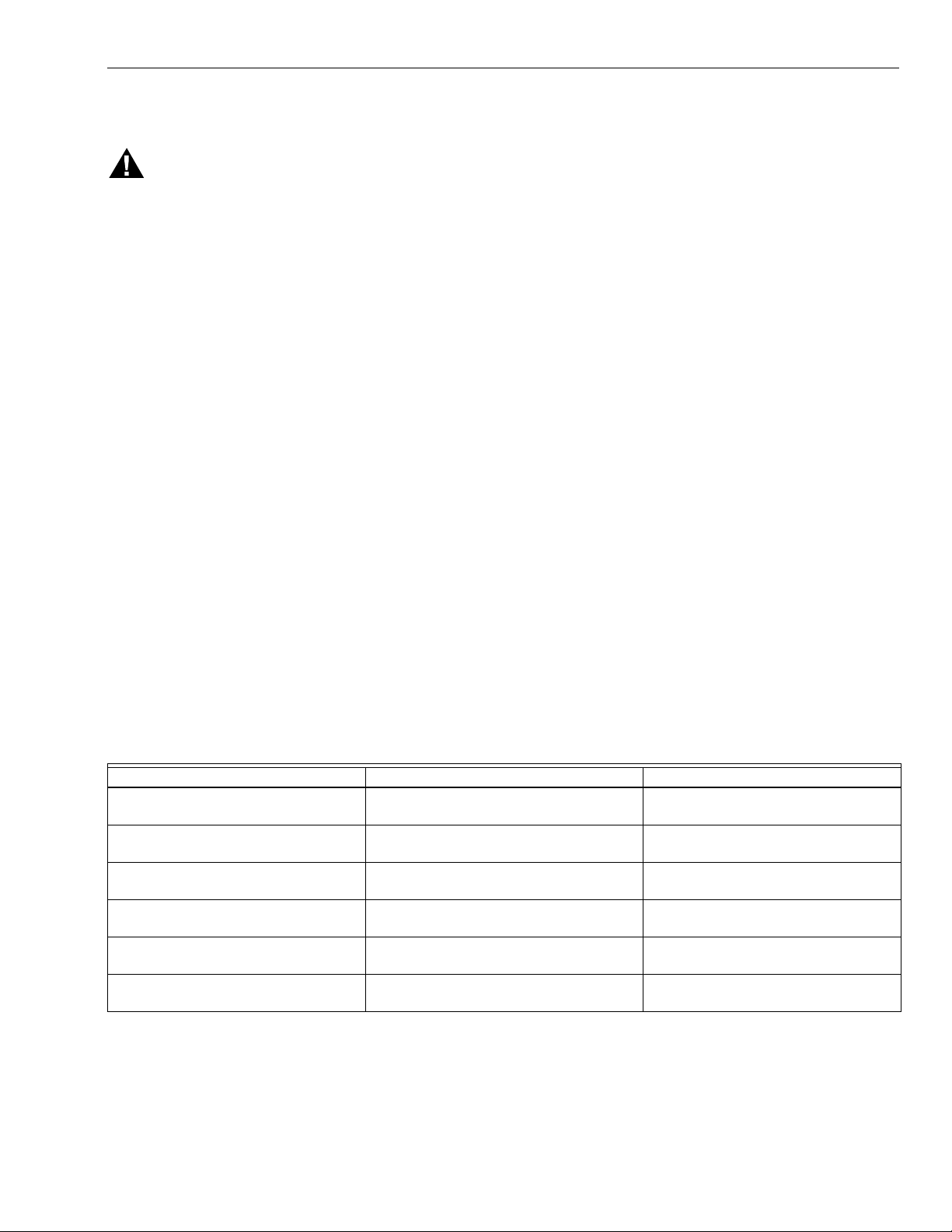
Table 2. Recommended Grounding Practices.
Ground Type Recommended Practice
Earth ground (subbase and relay
module).
1.
Use to provide a connection between the subbase and the control panel of the
equipment. Earth grou nd mu st b e c ap abl e of conducting enough current to blow
the 20A fuse (or breaker) in the event of an internal short circuit.
2.
Use wide straps or brackets to provide minimum length, maximum surface area
ground conductors. If a leadwire is required, use 14 AWG copper wire.
3.
Make sure that mechanically tightened joints along the ground path are free of
nonconductive coatings and protected against corrosion on mating surfaces.
Signal ground (Keyboard Display
Module, Data ControlBus Module™,
Communications Interface
Use the shield of the signal wire to ground the device to the signal ground terminals—
3(c)—of each device. Connect the shield at both ends of the daisy chain to earth
ground.
ControlBus™ Module).
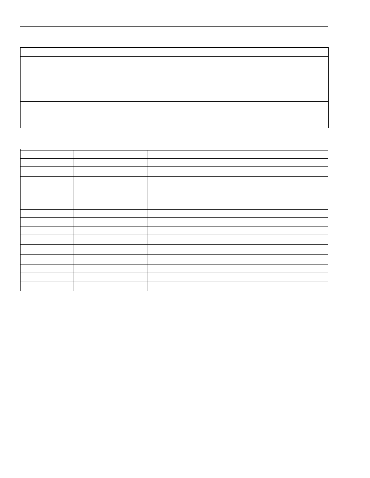
Table 3. Terminal Ratings.
Terminal Number Description Ratings (RM7890A,B,C) Ratings (EC7890A,B)
G Flame Sensor Ground — —
Earth G
Earth Ground
a
——
L2(N) Line Voltage Common — —
3 Line Voltage Supply (L1) 120 Vac (+10%/-15%), 50 or
60 Hz (±10%).
b
220-240 Vac (=10%/-15%), 50 or 60 Hz
(±10%).
4 Alarm 120 Vac, 1A pilot duty. 220-240 VAc, 1A pilot duty.
5Unused — —
6 Burner Controller and Limits 120 Vac, 8A run, 43A inrush. 220-240 Vac, 5A (maximum).
7Unused — —
8 Pilot Valve/Ignition.
9 Main Fuel Valve.
10 Ignition
120 Vac.
120 Vac.
c
c
120 Vac, 4.5A ignition.
c
220-240 Vac, 4A at P.F. = 0.5, 20A inrush.
220-240 Vac, 4A at P.F. = 0.5, 20A inrush.
220-240 Vac, 4A at P.F. = 0.2.
F(1 1) Flame Sensor 60 to 220 Vac, current limited. 60 to 220 Vac, current limited.
12 to 21 Unused. — —
22 Shutter 120 Vac, 0.5A (RM7890B).
a
The RM7890 must have an earth ground providing a connection between the subbase and the control panel or the equipment.
220-240 Va c (EC7890B only).
d
The earth ground wire must be ca pa ble of con ductin g the current to blow the 20A fuse (or breaker) in even t of an in tern al s hort
circuit. The RM78 90 nee ds a l ow i mp eda nc e g roun d c on nec ti on to the equipment fra me w hi ch, in tur n, needs a low impe da nce
connection to earth ground. For a ground path to be low impedance at RF frequencies, the connection must be made with minimum length conductors having maximum surface areas. Wide straps or brackets rather than leadwires are preferred. Be careful to verify that mechanically tightened joints along the ground path, such as pipe or conduit threads or surfaces held together
with fasteners, are free of nonconductive coatings and are protected against mating surface corrosion.
b
2000 VA maximum connected load to the RM7890 Assembly.
c
See Tables 4 and 5 for device load combinations.
d
Requires 220-240 to 120 Vac, 10 Va minimum stepdown transformer to drive the shutter.
66-1089—3 4
Page 5

RM7890A,B,C/EC7890A,B 7800 SERIES RELAY MODULES
CAUTION
Table 4. Combinations for Terminals 8, 9, and 10.
Combination No. Pilot Fuel 8 Main 9 Ignition 10
1 C F No Load
2 B F No Load
3FFA
4 F No Load A
5DFA
6DDA
7 D No Load A
T able 5. Compositio n of Each Combinatio n.
AB C D F
4.5A ignition 50 VA Pilot Duty
plus 4.5A ignition.
180 VA ignition plus motor
valves with: 660 V A i nrush,
360 V A op en, 250 VA hold.
Final Wiring Check
1.
Check the power supply circuit. The voltage and
frequency tolerance must match those of the
RM/EC7890. A separate power supply circuit can be
required for the RM/EC7890. Add the required
disconnect means and overload protection.
2.
Check all wiring circuits and complete the Static
Checkout in Table 7 before installing th e RM/EC789 0 on
the subbase.
3.
Install the relay module.
4.
Restore the panel power.
STATIC CHECKOUT
After checking all wiring, perform this checkout before
installing the RM/EC7890 on the subbase. These tests verify
the Q7800 Wiring Subbase is wired correctly, and the external
controllers, limits, interlocks, actuators, valves, transformers,
motors and other devices are operating properly.
WARNING
Explosion Hazard.
Can cause serious injury, death or equipment
damage.
1. Close all manual fuel shutoff v alve(s) before star ting
these tests.
2. Use extreme care while testing the system. Line
voltage is present on most terminal connections
when power is on.
3. Open the master switch before installing or
removing a jumper on the subbase.
4. Before continuing to the next test, be sure to
remove test jumper(s) used in the previous test.
5. Replace all limits and interlocks that are not
operating properly. Do not bypass limits and
interlocks.
2A Pilot Duty. 65 VA Pilot Duty plus motor
Equipment Damage Hazard.
Can cause equipment damage or equipment
failure.
Do not perform a dielectric test with the RM/EC7890
installed. Internal surge protect ors break dow n and
conduct a current, causing the RM/EC7890 to fail the
dielectric test or possibly destroy the internal lightning
and high current protection.
valves with: 3850 VA inrush,
700 VA Open, 250 VA hold.
Equipment Recommended
1.
Voltmeter (1M ohm/volt minimum sensitivity) set on the
0 to 300 Vac scale.
2.
Two jumper wires, No. 14 wire, insulated, 12 in.
(304.8 mm) long with insulated alligator clips at both
ends.
General Instructions
1.
Perform all applicable tests listed in the Static
Checkout, Table 6, in the order listed.
2.
Make sure all manual fuel shutoff valves are closed.
3.
For each test, open the master switch and install the
jumper wires between the subbase wiring terminals
listed in the Test Jumpers column.
4.
Close the master switch before obs erving the operati on.
5.
Read the voltage betwe en the s ubbas e wiring te rminal s
listed in the Voltmeter column.
6.
If there is no voltage or the oper ation is abnorma l, check
the circuits and external d evices as describe d in the la st
column.
7.
Check all wiring for proper connections, tight terminal
screws, and appropr iate wire and wiring techniques .
8.
Replace all damaged or incorrectly sized wires.
9.
Replace faulty controllers, limits, interlocks, actuators,
valves, transformers, motors and other devices, as
required.
10.
Make sure normal operation is obtained for each
required test before continuing the checkout.
11.
After completing each test, be sure to remove the test
jumper(s).
5 66-1089—3
Page 6

RM7890A,B,C/EC7890A,B 7800 SERIES RELAY MODULES
IMPORTANT
WARNING
Explosion Hazard.
Can cause serious injury or death.
Be sure all manual fuel shutoff valves are closed.
Table 6. Static Checkout.
Test
No. Test Jumpers Voltmeter Normal Operation
1 — 4-L2 Line Voltage. 1. Master switch.
2 — 6-L2 Line Voltage. 1. Limits.
3 3-10 — Ignition spark (if ignition
transformer is connected to
terminal 10).
4 3-8 — 1. Ignition spark (if ignition
transformer is connected to
terminal 8).
2. Automatic pilot valve opens (if
connected to terminal 8).
NOTE: Refer to wiring diagram of
system being tested.
5 3-9 — Automatic fuel valve(s) opens. If
using direct spark ignition, check
the first stage fuel valve(s) instead
of the pilot valve.
6 3-4 — Alarm (if used) turns on. 1. Alarm.
FINAL
Low fuel pressure limits, if used, could be open.
Bypass them with jumpers for the remaining static
tests (if required).
If Operation is Abnormal, Check the Items
Listed Below
2. Power connected to the master switch.
3. Overload protection (fuse, circuit breaker,
etc.) has not opened the power line.
2. Burner control.
1. Watch for spark or listen for buzz.
a. Ignition electrodes are clean
b. Ignition transformer is okay.
1. Watch for spark or listen for buzz:
a. Ignition electrodes are clean.
b. Ignition transformer is okay.
2. Listen for click or feel head of valve for
activation:
a. Actuato r, if used.
b. Pilot valve.
Same as test number 4. If using direct spark
ignition, check the firs t stage fuel valve (s) instead
of the pilot valve.
CAUTION
Equipment Damage Hazard.
Can cause serious equipment damage.
After completing these tests, open the master switch, remove all test jumpers from the subbase terminals, and
remove any bypass jumpers from the low fuel pressure limits to prevent equipment damage.
66-1089—3 6
Page 7

3
1
RESET
PUSHBUTTON
STATUS LEDs
LIMITS CONTROLLER
3K1
DDL
DDL
COMMUNICATIONS
CONFIGURATION
JUMPERS
MICROCOMPUTER
SAFETY RELAY
CIRCUIT
6
OPTIONAL KEYBOARD
DISPLAY MODULE
RS485
1
2
REMOTE
3
RESET
L1
(HOT)
RELAY
DRIVE
CIRCUIT
2K
3K
4K
1K
POWER SUPPLY
1K1 2K2
L2
2
FLAME SIGNAL
PLUG-IN
FLAME
TEST
AMPLIFIER
RELAY
STATUS
FEEDBACK
AND LINE
VOLTAGE
INPUTS
CONTROL
POWER
5K1
4K1
2K1
INDICATES FEEDBACK SENSING
TO RELAY STATUS FEEDBACK
AND LINE VOLT INPUTS
FIELD WIRING
INTERNAL WIRING
10
8
9
4
RM7890A,B,C/EC7890A,B 7800 SERIES RELAY MODULES
L2
TEST
JACK
F
G
22
IGNITION
PILOT
MAIN VALVE
ALARM
RM7890C
F
N. O.
3
1
NUMBERS IN CIRCLES ARE RELAY MODULE
TERMINAL NUMBERS.
2
PROVIDE DISCONNECT MEANS AND
OVERLOAD PROTECTION AS REQUIRED.
120 VAC, 50/60 HZ (RM7890); 220-240 VAC,
50/60 HZ (EC7890) POWER SUPPLY.
3
EC7890 REQUIRES A 220/240 VAC TO 120 VAC,
10VA, STEPDOWN TRANSFORMER (NOT
SUPPLIED) WHEN USING C7012E, F; C7061A,
AND C7076A FLAME DETECTORS.
M11586A
Fig. 1. Internal block diagram of the RM/EC7890.
7 66-1089—3
Page 8

RM7890A,B,C/EC7890A,B 7800 SERIES RELAY MODULES
L1
(HOT)
L2
1
LED
DISPLAY
BURNER
START
OPERATING
CONTROLLER
AND LIMITS
FLAME
SIGNAL
MASTER
SWITCH
INITIATE
POWER
LINE VOLTAGE
ALARM
2
BURNER
CONTROLLER/LIMITS
INTERMITTENT
PILOT/IGNITION
MAIN FUEL
VALVE(S)
IGNITION
FLAME DETECTOR
6
7
00
STANDBY
POWER
SAFE START CHECK
SAFE-
START
POWER
LIMITS AND BURNER CONTROL CLOSED
00
PFEP
4 OR 10 SEC
ALARM
IGNITION
Q7800
G
L2
3
(L1)1314
4
5
6
7
8
9
10
F
5
4/10
8
RUN
POWER POWER
PILOT
FLAME
MAIN
INTERMITTENT PILOT
PILOT
FLAME
MAIN
ALARM
10
MAIN VALVE
FLAME PROVING
12
15
16
17
3
18
19
20
21
4
22
8
9
3
TO
FOR DIRECT SPARK IGNITION (OIL
OR GAS)
IGNITION
10
TRANSFORMER
8
MAIN VALVE
9
STANDBY
POWER
9
6
S S C
L2
USING EC7890, A 220-240 VAC TO 120 VAC, 10 VA MINIMUM STEP-DOWN
1
120V, 50/60 HZ (RM7890); 220-240, 50/60 HZ (EC7890). POWER SUPPLY.
PROVIDE DISCONNECT MEANS AND OVERLOAD PROTECTION
AS REQUIRED.
2
INSTALL A LINE VOLTAGE CONTROLLER IN SERIES WITH THE LIMITS.
IF USING A LOW VOLTAGE CONTROLLER IS DESIRABLE, INSTALL AN
EXTERNAL RELAY WITH THE N. O. CONTACTS IN SERIES WITH
THE LIMITS. THE LOW VOLTAGE RELAY COIL WILL BE IN THE LOW
VOLTAGE CONTROLLER CIRCUIT. NOTE THAT IT MAY BE NECESSARY
TO PROVIDE AN EXTERNAL LOW VOLTAGE TRANSFORMER.
DO NOT CONNECT ANY WIRES TO UNUSED TERMINALS.
3
TERMINAL 22 IS ONLY ON THE RM/EC7890B.
4
FOR A CONTINUOUS OR STANDING PILOT, USE THE RM7890C OR
5
INSTALL AN EXTERNAL RELAY TO SWITCH THE F LEAD. THE RELAY
MUST HAVE GOLD-CLAD OR GOLD-FLASH CONTACTS AND A LINE
VOLTAGE COIL. POWER THE RELAY COIL FROM THE Q7800 SUBBASE
TERMINAL 8. CONNECT THE RELAY CONTACTS BETWEEN THE F LEAD
OF THE DETECTOR AND THE F TERMINAL OF THE Q7800 SUBBASE.
THE R4222N1002 OR R4222V1002 RELAY IS ACCEPTABLE TO USE IN
THIS TYPE OF APPLICATION. USE THE N.O. PILOT DUTY CONTACTS.
6
TRANSFORMER (NOT PROVIDED) MUST BE USED TO DRIVE THE
SHUTTER (C7012E,F; C7061; C7076A,D DETECTORS).
7
SEE FLAME DETECTOR SPECIFICATION FOR CORRECT WIRING.
8
RM7890A1031 PFEP IS 30 SECOND FIXED.
MAIN FUEL VALVE IS ENERGIZED DURING PFEP ONCE FLAME IS PROVEN.
9
(RM7890B1030 WAITS FOR COMPLETION OF PFEP BEFORE ENERGIZING
THE MAIN VALVE.)
Fig. 2. Wiring subbase and operating sequence chart for RM/EC7890.
66-1089—38
M11587C
Page 9

Mounting RM/EC7890 Relay Module
1.
Mount the RM/EC7890 vertically on the Q7800
Subbase, or mount horizontally with the knife blade
terminals pointing down. When mounted on the
Q7800A, the RM/EC7890 must be in an electrical
enclosure.
2.
When mounting in an electrical enclosure, provide
adequate clearance for servicing, installation and
removal of the RM/EC7890, KDM , flame am plifier , flam e
amplifier s ignal voltage probes, electrical signal voltage
probes, and electrical con nections.
a. Allow an additional two inches (51 mm) below the
RM/EC7890 for flame amplifier mounting.
b. Allow an optional three-inch (76 mm) minimum to
both sides of the RM/EC7890 for electrical signal
voltage probes.
WIRING
SUBBASE
RM7890A,B,C/EC7890A,B 7800 SERIES RELAY MODULES
3.
Make sure no subbase wiring is projecting beyond the
terminal blocks. Tuck in wiring against the back of the
subbase so it does not interfere with the knife blade
terminals or bifurcated contacts.
IMPORTANT
Install the RM/EC7890 with a plug-in motion rather
than a hinge action.
4.
Mount the RM/EC7890 by aligning the four L-shaped
corner guides and knife blade terminals with the
bifurcated contacts on the wiring subbase and securely
tightening the two screws witho ut de forming the plastic.
Mounting Other System Components (Fig. 3)
Refer to the applicable specifications for mounting other
system components .
HONEYWELL
DUST
COVER
RESET
BUTTON
SEQUENCE
STATUS
LED PANEL
RELAY
MODULE
CONFIGURATION
JUMPERS
BURNER CONTROL
POWER
PILOT
MAIN
FLAME
ALARM
RESET
CAPTIVE
MOUNTING
SCREW
FLAME
AMPLIFIER
Fig. 3. RM/EC7890 Relay Module exploded view.
9 66-1089—3
M11588A
Page 10

RM7890A,B,C/EC7890A,B 7800 SERIES RELAY MODULES
PRINCIPAL TECHNICAL FEATURES
The RM7890 provides all cust om ary fla me safeguard
functions as well as significant advancements in safety,
annunciation, and system diagnostics.
Safety Shutdown (Lockout) Occurs if:
1.
INITIATE PERIOD
a. AC line power errors occurred, see Operation.
b. Configuration jumpers have been changed (after
200 hours) .
c. Four minute INITIATE period has been exceeded.
2.
STANDBY PERIOD
a. Flame signal is present after 40 seconds.
b. Ignition/intermittent pilot valve terminal is energized.
c. Internal system fault occurred.
d. Main valve terminal is energized.
e. Three second Flame Failure Response Time
(FFRT) Amplifier is installed and configuration
3.
4.
5.
jumper is selected for relight (see Table 3).
SAFE START CHECK (EXCEPT RM7890C)
a. Ignition/intermittent pilot valve terminal is energized.
b. Internal system fault occurred.
c. Main valve terminal is energized.
PILOT FLAME ESTABLISHING PERIOD (PFEP)
a. Ignition/intermittent pilot valve terminal is not
energized.
b. Internal system fault occurred.
c. Main valve terminal is energized.
d. No flame present at end of PFEP.
RUN PERIOD
a. Ignition terminal is energized.
b. Internal system fault occurred.
c. Main valve terminal is not energized.
d. No flame present and configuration jumper is
selected for lockout.
e. Pilot valve terminal is not energized.
OPERATION
Sequence of Operation
The RM/EC7890 has the operating sequences listed below;
see Fig. 2. The RM/EC7890 LED provide positive visual
indication of the program sequence: POWER, PILOT, FLAME,
MAIN and ALARM.
Initiate
The RM/EC7890 enters the INITIATE sequence when the
relay module is powered. The RM/EC7890 can also enter the
INITIATE sequence if the relay module verifies voltage
fluctuations of +10/-15% or frequency fluctuations of ±10%
during any part of the operating sequence. The INITIATE
sequence lasts for ten seconds unless the voltage or
frequency tolerances are not met. When the tolerances are
not met, a hold condition is initiated and is displayed on the
optional KDM for at least five seconds. When the tolerances
are met, the INITIATE sequence restarts. If the condition is not
corrected and the hold condition exists for four minutes, the
RM/EC7890 locks out. Causes for hold conditions in the
INITIATE sequence:
a. AC line dropout detection.
b. AC line noise that can prevent a suf ficie nt reading o f
the line voltage inputs.
c. Brownouts caused by a low line voltage.
NOTE: If a 3.0 second flame failure response amplifier is
installed and configuration jumper JR2 is intact, the
RM/EC7890 locks out. JR2 must be clipped.
Standby
The RM/EC7890 is ready to start an operating sequence
when the operating contro l inpu t (termin al 6) reco gnize s a cal l
for heat. The burner switch, limits, operating limit control and
all microcomputer monitored circuits must be in the correct
state for the RM/EC7890 to continue into the Safe Start
Check.
Normal Start-Up Safe Start Check (Except Rm7890c)
The RM/EC7890 verifies that a flame or flame simulating
condition does not ex ist and p r oc eed s in to the Igni tion Trial. If
a flame or flame simulating condition is present, the
RM/EC7890 remains in th e STANDBY period. RM7890C
checks its internal components for flame simulating
conditions.
Ignition Trials
a. Pilot Flame Establishing Period (PFEP):
(1) The pilot valve and ignition transformer, termi-
nals 8 and 10, are energized. The RM/EC7890
has an intermittent pilot valve, terminal 8.
RM7890C closes inte rnal re lay contac t in the " F"
lead.
(2) Flame must be proven by the end of the four- or
ten-second PFEP (30 seconds for
RM7890A1031) or a safety shutdown occurs.
(3) Once flame is pro ven, the ignition, te rminal 10, is
de-energized and the main valve, terminal 9, is
energized. The RM7890B1030 finishes the
4- or 10-second PFEP before the main valve is
energized.
Run
The RM/EC7890 is now in RUN and remains in RUN until the
controller input, terminal 6, opens, indicating that the demand
is satisfied or a limit has opened.
66-1089—310
Page 11

SETTINGS AND ADJUSTMENTS
Selectable Site-Configurable Jumpers
The RM/EC7890 has two site-configurable jumper options,
see Fig. 4 and Table 7. If necessary, clip the site-configurable
jumpers with side cutters and remove the resistors from the
relay module.
SELECTABLE CONFIGURATION JUMPERS
1 2
SERVICE NOTE
Clipping and removing a site-configurable jumper enhances
the level of safety. If using three-second amplifier, siteconfigurable jumper JR2 must be clipped and removed. If not
removed, an F46 Lockout occurs.
Site-Configurable Jumper Options.
Jumper
Number Description Intact Clipped
a
JR1
JR2
a
Not Applicable for RM7890A1031 (30 second PFEP).
Pilot Flame Establishing
Period (PFEP)
c
Flame Failure Action
10
seconds
Relight
d
b
4
seconds
Lockout
JR1 removed.
b
30 seconds for RM7890A1031.
c
Not applicable for RM7890C (Standing Pilot).
d
The Relight feature (JR2 inta ct) requi res a 0.8 s econd FFR T
Flame Amplifier. The EC/RM7890 locks out and indicates a
Fault 46 if a 3 second FFRT is used and jumper JR2 is not
clipped and removed.
b
1
JR2 REMOVED FROM RM7890C.
2
RM7890A1031 PFEP IS FIXED AT 30 SECONDS, IF JR1 IS
INTACT OR CLIPPED.
Fig. 4. Selectable site-configurable jumpers.
M11589A
11 66-1089—3
Page 12

Home and Building Control Home and Building Control
Printed in U.S.A. on recycled
paper containing at least 10%
post-consumer paper fibers.
Honeywell Honeywell Limited-Honeywell Limitée
1985 Douglas Drive North 35 Dynamic Drive
Golden Valley, MN 55422 Scarborough, Ontario
M1V 4Z9
66-1089—3 G.R. Rev. 10-00 www.honeywell.com
 Loading...