

Page 1
Page 2
2 Tw in Ci ty IM 4 20 5
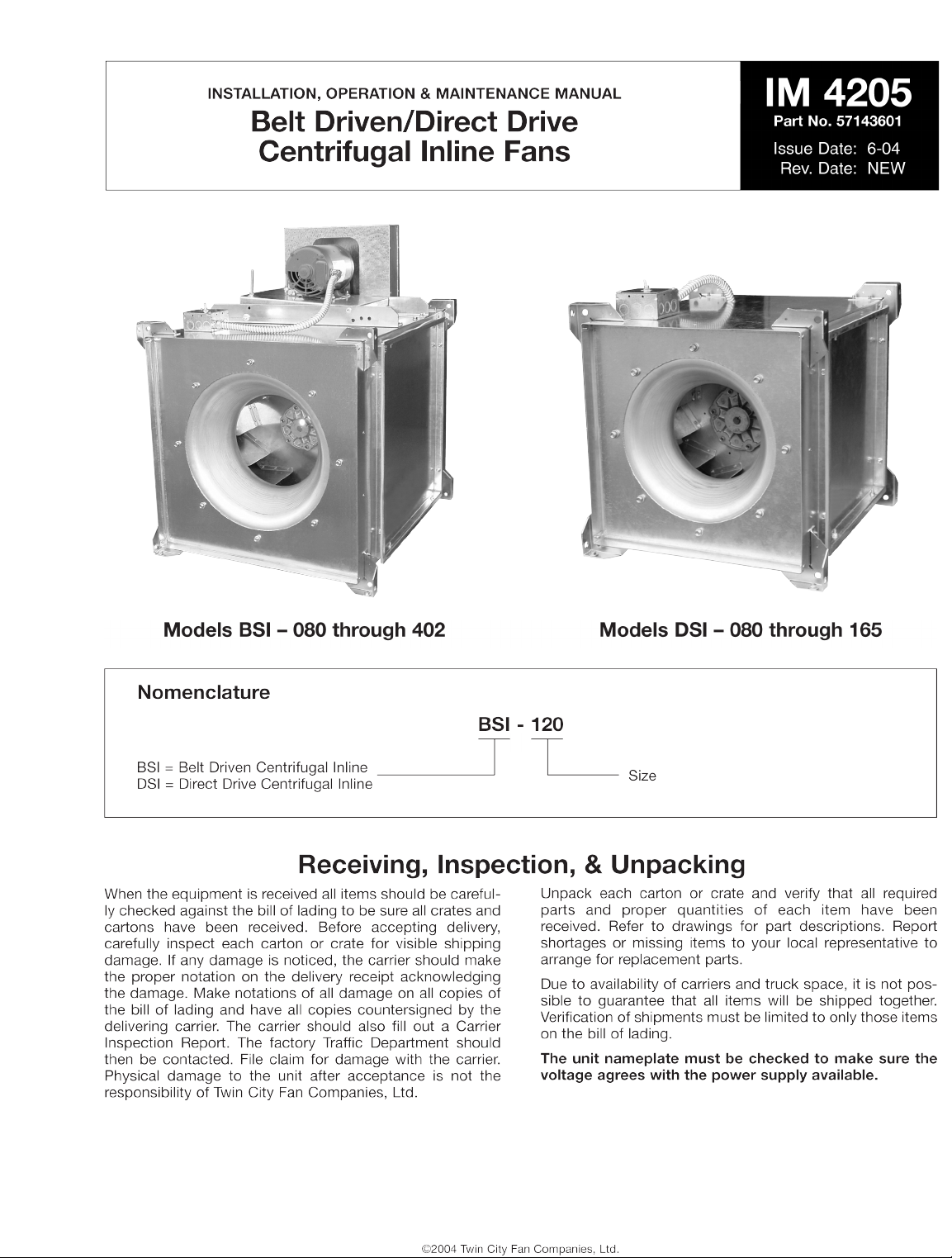
Installation
General
CAUTION: Sheet metal parts, screws, clips and similar
items inherently have sharp edges, and it is necessary
that the installer and service personnel exercise caution.
The installation of this equipment shall be in accordance
with the regulations of authorities having jurisdiction and
with all applicable codes.
This equipment is to be installed by an experienced installation company and fully trained personnel.
The mechanical installation of the inline centrifugal fan consists of making final connections between the unit, building
services, and duct connections.
1. These units have been run at the factory to insure excellent operation.
2. Before installing unit in ductwork (if damper is to be used)
make sure the damper is correctly installed. Refer to
Ta bl e 6 f or co rr ec t d am pe r s iz e .
3. Connect supply leads to the disconnect switch.
4. Check power supply to insure it is proper for the motor
supplied.
5. Determine if wheel is free to rotate and not subject to
misalignment in shipping or installation.
6. Install belts and adjust tension and lock capscrew in slot.
Te ns i on sh ou l d b e c he c ke d an d re se t , i f n ec e ss a ry, af t er
48 hours of operation. (BSI models only.)
7. Apply power and check wheel for proper rotation. Also
check unit RPM, motor volts and amperes, to insure
proper operation.
Check, Test & Start Procedure
WARNING
Electric shock hazard. Could cause severe injury or death. Failure to bond the frame of this equipment to the building
electrical ground by use of the grounding terminal provided or other acceptable means may result in electrical shock.
Disconnect electric power before servicing equipment. Service to be performed only by qualified personnel.
BEFORE STARTUP: Disconnect power to this unit before
servicing the unit.
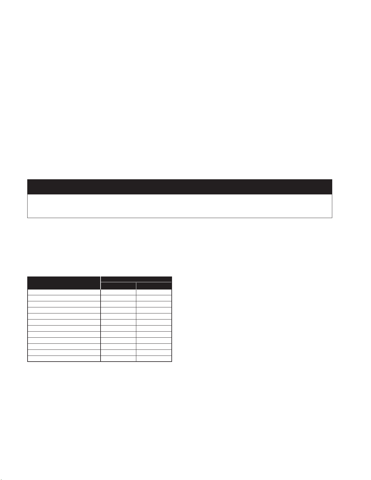
1. Check to verify that the wheel is free to rotate.
2. Verify that supply voltage on the line side of disconnect
agrees with voltage on unit identification plate and is within the utilization voltage range as indicated in Table 1.
Tabl e 1. U ti li za ti on Vo lt ag e Ra ng es
3. On three-phase units check and calculate phase unbalance as follows:
% Voltage Unbalance = 100 x max. voltage deviation
from avg. voltage ÷ avg. voltage
Example: Determine the percent voltage unbalance given
voltages of 220, 216 and 213.
How To Use The Formula:
a. Avg. Voltage = 220 + 216 + 213 = 649 ÷ 3 = 216
b. Max. Voltage Deviation From Avg. Voltage =
220 – 216 = 4
c. % Voltage Unbalance = 100 x (4 ÷ 216) = 1.8%
Voltage unbalanc e sh oul d no t ex ceed 2%.
4. Apply power to unit and check rotation of wheel with the
directional arrow on the unit.
WARNING: All units run in a clockwise direction when viewed
from the air intake. If allowed to operate in the wrong direction, the motor will be overloaded and burn out
.
WARNING: Special attention should be paid to checking
three-phase units for rotation. For three-phase, rotation can
be changed by interchanging any two of the three line leads.
If unit is installed on temporary wiring, it should be rechecked
when permanently installed. Motor burn-out or tripped overload protection devices are usually the result of incorrect rotation.
5. Electrical Input Check: Perform check of fan ampere
draw and verify that motor nameplate amps are not
exceeded. Take account of the service factor range if
motor is nameplated above a 1.0 service factor.
6. Fan RPM Check: Fan the RPM should be checked and
verified with a tachometer. Refer to Table 2 for maximum
fan RPM values.
WARNING: Running the fan at an RPM greater than the maximum RPM value in Table 4 will overload the fan motor and
lead to premature motor failure.
WARNING: Do not replace motor sheave with one larger in
diameter. Do not replace fan sheave with one smaller in
diameter. The sheave ratios are set so that the motor will not
be overloaded within the range of the adjustable sheave.
SYSTEM VOLTAGE/ UTILIZATION VOLTAGE
UNIT NAMEPLATE MIN. MAX.
115/60/1 104 127
208-230/60/1 or 208-230/60/3 187 253
230/60/1 or 230/60/3 207 253
277/60/1 249 305
200/60/3 180 220
380/60/3 342 418
460/60/3 414 506
575/60/3 517 633
110/50/1 99 121
220/50/1 198 242
380-415/50/3 342 456
440/50/3 396 484
Page 3

Tw in Ci ty IM 4 20 5 3
MODEL MOTOR MAXIMUM
BSI HP FAN RPM
1/4 2250
1/3 2500
080 1/2 2860
3/4 3260
13590
1/4 2015
1/3 2230
090 1/2 2550
3/4 2920
13205
1/4 1565
1/3 1725
100 1/2 1980
3/4 2255
12480
1/4 1290
1/3 1420
120
1/2 1630
3/4 1865
12045
1-1/2 2345
1/4 1450
1/3 1600
120HP
1/2 1840
3/4 2105
12315
1-1/2 2655
1/4 1075
1/3 1190
135
1/2 1370
3/4 1565
11720
1-1/2 1970
1/4 1200
1/3 1350
135HP
1/2 1550
3/4 1765
11945
1-1/2 2225
1/4 920
1/3 1020
1/2 1170
150 3/4 1335
11465
1-1/2 1680
21845
1/3 1140
1/2 1320
150HP
3/4 1510
11660
1-1/2 1900
22090
1/3 875
1/2 1005
3/4 1150
165 11260
1-1/2 1445
21590
31820
1/2 1130
3/4 1290
165HP
11415
1-1/2 1620
21785
32040
Tabl e 2. M ax im um Fan R PM ( BS I)
MODEL MOTOR MAXIMUM
BSI HP FAN RPM
1/3 750
1/2 865
3/4 985
180 11085
1-1/2 1240
21365
31560
1/2 970
3/4 1105
180HP
11215
1-1/2 1390
21530
31750
1/3 630
1/2 720
3/4 825
210 1905
1-1/2 1040
21140
31305
1/2 810
3/4 925
210HP
11015
1-1/2 1165
21280
31465
1/3 520
1/2 600
3/4 685
225
1750
1-1/2 865
2950
31085
51285
3/4 785
1860
225HP
1-1/2 985
21085
31240
51470
1/2 505
3/4 575
1630
245
1-1/2 725
2795
3910
51080
7-1/2 1235
1730
1-1/2 835
245HP
2915
31050
51245
7-1/2 1425
1/2 420
3/4 480
1525
270
1-1/2 605
2665
3760
5900
7-1/2 1030
MODEL MOTOR MAXIMUM
BSI HP FAN RPM
1605
1-1/2 695
270HP
2760
3870
51030
7-1/2 1185
1450
1-1/2 515
300
2565
3645
5770
7-1/2 880
1515
1-1/2 590
300HP
2650
3745
5880
7-1/2 1010
1380
1-1/2 435
2475
330 3545
5650
7-1/2 745
10 820
1-1/2 500
2550
330HP
3630
5745
7-1/2 855
10 940
1320
1-1/2 370
2405
365 3465
5550
7-1/2 630
10 695
1-1/2 420
2460
365HP
3530
5625
7-1/2 720
10 790
1-1/2 310
2340
402
3390
5465
7-1/2 535
10 585
1-1/2 355
2390
3445
402HP 5530
7-1/2 605
10 670
15 765
Page 4

4 Tw in Ci ty IM 4 20 5
1. The motors in these units are equipped with permanently sealed ball bearings. They require no lubrication for the
life of the motor.
2. Fan shaft pillow block bearings on larger units are
equipped with grease gun fittings. These bearings are
factory lubricated and, with normal operation, will need
no lubrication for 3 to 6 months. (BSI models only.)
3. For pillow block bearings, use a low pressure grease gun
with Alvania #2 or #3 grease or equivalent. Only a few
strokes of the gun are required. Excess grease will be
forced out through the bearing pressure relief holes. Use
of a high pressure gun, however, is liable to blow the
bearing seals.
4. Belt tension is adjusted at the factory. It should be readjusted after a break-in period of 24 hours of actual operation. (BSI models only.)
5. To adjust belt tension, loosen the hex head screw in the
tab of the motor plate. Snug belts by pulling on the motor
with a force of 15 lbs. for single belts and 30 lbs. for double belts. Retighten screw before releasing motor.
6. Belt condition and tension should be checked every 3 to
6 months depending on service. If belt tension is too
tight, there is a possibility of overloading the motor as
well as causing undue belt wear. If the belt tension is too
slack, then the wheel will fall off in RPM, air delivery will
decrease and the belts will wear quite rapidly. (BSI models only.)
7. If the air handled by the unit is dust or grease laden, a
regular inspection and cleaning of the backdraft damper
and the wheel will ensure smooth, efficient operation.
Maintenance
Speed Control (Field Installed Only) — DSI Models (Optional)
Speed control is available for DSI models using 115/60/1
open type PSC or shaded pole motors. The speed controllers are of solid-state (tri-ac) design. The speed control
features include RFI filter, minimum speed trim adjustment
capability, and built-in on/off line switch. The controller is
designed to start motor on high speed for better start-up
characteristics.
Installation
Connect speed controller in series with motor and AC line
(115V only). Never connect speed controller across AC line.
See Figure 2.
Minimum Speed Setpoint
All controls are factory set to 65V±3V output as standard
with an input voltage of 120V. If different minimum speed is
desired, the control may be adjusted by turning minimum
speed pot clockwise to decrease minimum speed and
MOTOR DSI MOTOR PART NO. SPEED CONTROLLER
AMP
RPM HP MODEL ODP TE PART NO.
1/6 080, 090, 100, 120, 135N – 73505106
66805601 5
1075
1/4 135, 150N 73500214 73505210
1/2 150, 165N 73500413 73505408
66805701 10
3/4 165 73500510 73505506
1/4 080, 090 73500215 – 66805601 5
1/3 100 73500316 73505311
66805701 10
1/2 120 73500415 73505409
1650 1 135 73500610 73505606 66806001 15
3/4 135N 73500509 73505507 66805701 10
1 1/2 150 73500705 73505606
66806001 15
1 150N 73500610 73505706
Figure 1. Low End Setpoint Adjustment
Figure 2. Connection Diagram, Speed Control
SETPOINT ADJUSTMENT
SCREW
SPEED CONTROLLER
AC
LINE
(115V)
SWITCH
TRI-AC
MOTOR
counterclockwise to increase minimum speed. Refer to
Figure 1.
Warning: If minimum speed is readjusted, verify unit
ampere draw does not exceed motor nameplate amps. Do
not operate unit in range where amp draw exceeds motor
nameplate.
Warning: Certain failure modes of solid-state controls
such as half-waving can cause high levels of DC, motor
overheating and motor burn-out. Therefore, a thermal overload protection (integral with motor) is required to limit the
maximum motor temperature under such a failure.
Caution: These motors operate more efficiently in the
ranges set from the factory. Operating motors outside these
ranges may cause motors to run hotter and substantially
shorten motor life.
Note: Lowering the minimum speed setpoint may
adversely affect motor start-up characteristics.
Tabl e 3. S pe ed Con tr ol le r Si ze ( DS I Mod els )
Page 5

Tw in Ci ty IM 4 20 5 5
Hanger Brackets
Shown on pages 5 and 6 are the typical dimensions (E and
F) for the hanger brackets that are supplied with these units.
The
9
⁄16" holes in these brackets can readily be used for
installing the units. To obtain optimum isolation, the BSI unit
should be installed with the motor above or below the fan
body.
Overhead Mounting
Floor Mounting
2.15
2.72
3.0
3.69
5.25
Neoprene
Isolator
Hanger Rod, Nuts &
Washe rs (B y I nstall er)
Bolt, Nuts &
Washe rs (I nclu ded)
Hanger Housing
Spring
Isolator
BSI/DSI
Unit
Hanger Bracket
NEOPRENE ISOLATOR SPRING ISOLATOR
BSI/DSI
Unit
Finished Floor
3.50
1.50
BSI: Belt Driven Centrifugal Inline Fans
MODEL B C F DAMPER AVG. SHIP
BSI
A
SQ. SQ.
DE
MAX. SIZE WT. (LBS.)
080 22.50 13.00 11.25 20.19 14.50 12.00 11.00 x 11.00 111
090 23.00 15.25 13.50 20.69 16.75 12.00 13.00 x 13.00 116
100 26.00 17.81 16.06 23.69 19.31 12.00 16.00 x 16.00 135
120/120HP 25.50 19.38 17.62 23.19 20.88 12.00 17.50 x 17.50 151
135/135HP 28.00 21.53 19.75 25.75 23.03 12.00 19.50 x 19.50 161
150/150HP 30.50 23.69 21.94 28.25 25.19 12.00 21.50 x 21.50 200
165/165HP 36.00 26.38 24.62 33.75 27.88 14.50 24.50 x 24.50 232
180/180HP 39.25 28.88 27.12 37.00 30.38 14.50 27.00 x 27.00 266
210/210HP 43.00 32.19 30.44 40.75 33.69 14.50 30.00 x 30.00 300
225/225HP 45.50 34.00 32.25 43.25 35.50 14.50 32.00 x 32.00 385
245/245HP 48.50 37.50 35.75 46.25 39.00 16.00 35.50 x 35.50 468
270/270HP 54.50 40.00 38.25 52.25 41.50 16.00 38.00 x 38.00 551
300/300HP 59.50 44.00 42.25 57.25 45.50 16.00 42.00 x 42.00 634
330/330HP 65.00 48.69 46.94 62.75 50.19 17.00 46.50 x 46.50 792
365/365HP 65.00 50.00 48.25 62.75 51.50 17.00 48.00 x 48.00 892
402/402HP 71.50 55.25 53.50 69.25 56.75 20.00 53.00 x 53.00 1022
BELT
GUARD
B SQ.
E
C SQ.
F MAX.
B + 3.13
MOTOR
COVER
DISCONNECT
SWITCH
1.13
C SQ.
D
A
AIRFLOW
1.13
DIMENSIONS ARE NOT TO BE USED FOR CONSTRUCTION.
Page 6

 Loading...