

Page 1

J/E/C
ご使用の前に必ずこの取扱説明書をお読みください。
なお、取扱説明書は必要に応じてご覧になれるよう大切に保管してください。
Read this operation manual before using the product.
Keep the manual in place for future reference.
在使用本产品之前 , 请务必先仔细阅读本使用说明书。
请务必妥善保管好本书 , 以便日后能随时查阅。( 保留备用 )
请在充分理解内容的基础上 , 正确使用。
取 扱 説 明 書
OPERATION MANUAL
使 用 说 明 书
BCTV Zoom Lens
广播电视变焦镜头
XJ100x9.3B AF
XJ100x9.3B
XJ95x8.6B
XJ86x13.5B
XJ86x9.3B AF
XJ86x9.3B
XJ80x8.8B
XJ76x9B
XJ75x9.3B
XJ72x9.3B
XJ60x9B
XJ27x6.5B AF
XJ27x6.5B
XJ23x7B
Page 2

Page 3

ENGLISH
VERSION
The English version is the operation manual
for counties other than Japan.
Page 4
FCC REGULATIONS
This device complies with Part 15B of the FCC Rules. Operation is subject to the following two conditions: (1) This device
may not cause harmful interference, and (2) this device must accept any interference received, including interference
that may cause undesired operation.
Note: This equipment has been tested and found to comply with the limits for a Class A digital device, pursuant to Part
15B of the FCC Rules.
These limits are designed to provide reasonable protection against harmful interference when the equipment is operated
in a commercial environment. This equipment generates, uses, and can radiate radio frequency energy and, if not
installed and used in accordance with the instruction manual, may cause harmful interference to radio communications.
Operation of this equipment in a residential area is likely to cause harmful interference in which case the user will be
required to correct the interference at his own expense.
Do not make any changes or modications to the equipment unless otherwise specied in the manual. If such changes
or modications should be made, you could be required to stop operation of the equipment.
Canadian Radio Interference Regulations
CAN ICES-3(A)/NMB-3(A)
We, Canon Inc., in Japan and CANON EUROPE LTD., in U.K., conrm that the BCTV zoom lens is conformity with the
essential requirements of EC Directive(s) by applying the following standards:
EN55103-1 and EN55103-2
Note:
a) Applicable Electromagnetic Environments:
E1 (residential), E2 (commercial and light industrial), E3 (urban outdoors) and E4 (controlled EMC environment,
ex. TV studio).
b) Use of shielded cable is required to comply with limits specied by above standards.
NOTE: Above declaration is applicable to 12V DC input zoom lenses.
Dieses Produkt ist zum Gebrauch im Wohnbereich, Geschäfts- und Gewerbebereich sowie in Kleinbetrieben
vorgesehen.
Page 5
European Union (and EEA) only.
This symbol indicates that this product is not to be disposed of with your household waste, according
to the WEEE Directive (2002/96/EC) and your national law. This product should be handed over
to a designated collection point, e.g., on an authorized one-for-one basis when you buy a new
similar product or to an authorized collection site for recycling waste electrical and electronic
equipment (EEE). Improper handling of this type of waste could have a possible negative impact
on the environment and human health due to potentially hazardous substances that are generally
associated with EEE. At the same time, your cooperation in the correct disposal of this product will
contribute to the effective usage of natural resources. For more information about where you can
drop off your waste equipment for recycling, please contact your local city ofce, waste authority,
approved WEEE scheme or your household waste disposal service.
Your cooperation in the correct disposal of this product will contribute to the effective usage of natural resources and will
avoid incurring administrative sanctions according to art. 50 and following of Italian legislative decree 22/97.
For more information regarding return and recycling of WEEE products, please visit
www.canon-europe.com/environment.
(EEA: Norway, Iceland and Liechtenstein)
Page 6

PREFACE
Thank you for purchasing the Canon BCTV zoom lens. This operation manual explains the functions and operating instructions
for the Canon BCTV zoom lens. It also describes precautions for handling the lens. Read this operation manual carefully
before using the product. Also, keep this manual in a safe place where it can easily be referenced whenever necessary.
This operation manual is applicable for the following models:
Model name Operation system Interface
XJ100x9.3B AF
XJ100x9.3B
XJ95x8.6B
XJ86x13.5B
XJ86x9.3B AF
XJ86x9.3B
XJ80x8.8B
XJ76x9B
XJ75x9.3B
XJ72x9.3B
XJ60x9B
XJ27x6.5B AF
XJ27x6.5B
XJ23x7B
IESD
BA
BB
CA
CB
CC
HA
HB
HH
IA
IB
IH
PH
SA
SB
SC
SH
XJ60x9B
XJ27x6.5B
XJ23x7B
IESDA
PRODUCT CONFIGURATION
Make sure that the following items are included in a package.
(If you nd any item missing, please contact the dealer from whom you purchased this product.)
Lens Body
Oparation Manual
(this booklet)
CD-ROM
(technical documents)
*1
Dust Cap
(attached to the lens)
Connector Cap
(attached to the lens)
*2
Hood Cap (attached to the lens)
IS Operation Unit
*3
*1 Depending on the model, the technical documents may also be in the form of a booklet.
*2 The connector cap is provided to protect the interface connector(s) between the lens and the camera. For some lens models, two (2) pieces
are provided.
*3 The IS operation unit comes only with models with the IS function. However, it is available as an option with the XJ95x.
• Accessories other than those mentioned above may be required depending on the specications of your unit. For more
details, contact our sales representative.
• The illustrations shown on this page and subsequence pages are those of the XJ95x8.6B. Shapes of lens may be slightly
different between models.
• The illustrations of accessories shown in this booklet are those of standard specications. Shapes may be slightly different
between specications.
Page 7
GENERAL SAFETY
INFORMATION
Be sure to observe the safety warnings and cautions
provided on the product and in this operation manual.
Failure to observe these warnings and cautions may result
in injury or accident.
Read this operation manual carefully to familiarize yourself
with its contents and ensure that you can operate the
product properly.
Also, store this manual in a safe place where it can easily be
referenced whenever necessary.
This operation manual uses the following symbols and terms
to identify hazards in order to prevent accidents.
WARNING
T hi s i nd ic a tes a p ote n tia l ly
hazardous situation which, if not
heeded, may res ult in dea th or
serious injury to you or others. Be
sure to heed all warning notices to
ensure safe operation at all times.
CAUTION
Indicate s potentially hazardous
situations which, if not heeded, may
result in minor or moderate injury to
you or other persons, or property
damage.
* (NOTE)
Emphasizes essential information
which, if not heeded, may make the
product unworkable or cause it to
function improperly.
Helpful information for operation is
also provided.
HANDLING THE PRODUCT
WARNING
1. Never allow water or other liquids to enter or be spilled on
the product. Immediately stop using the product if water
or other liquids get inside the product. Otherwise, re or
electric shock could result.
2. Do not stare at the sun or any other source of highintensity light through the lens. Doing so could injure your
eyes.
CAUTION
1. Always grasp the specied portions of the lens when
transporting the lens, or when attaching or detaching it to
or from the camera head.
Otherwise, the lens may fall, possibly causing injury.
2. All mountings must be tightened securely. If any of the
mountings become loose, the lens may fall, possibly
causing injury.
3. Always grasp the connector itself when connecting
or disconnecting the demand cable. Pulling on the
cable portion may result in damage to the cable, such
as breakage of the conductors. Power leaking from a
damaged cable may present a re or electric shock
hazard.
4. Check periodically (for instance, every 6 months to 1
year) that all mountings are securely tightened. If any of
the mountings become loose, the lens may fall, possibly
causing injury.
5. If it becomes necessary to repair this product, or to
perform any operations or adjustments not mentioned in
this operation manual, contact Canon’s representative or
the dealer who originally supplied the lens.
6. When this product is used in direct sunlight, the inside
of the unit may be heated to high temperatures. When
it is expected that the unit is exposed to elevated
temperatures, take measures against heat as appropriate
on the customer’s side.
* (NOTE)
1. Protect the lens from strong impacts of shocks. Striking
or dropping the lens could damage it.
2. Since the lens is not completely waterproof, avoid directly
exposing the lens to rain or snow. When the lens has to
be used in rain or snow, provisions should be made to
prevent the lens from getting wet.
3. Under dusty conditions, the lens should be mounted or
dismounted with a cover placed over the mount so as to
prevent dust from entering the inside.
4. Do not bring the lens from an area with a very cold
ambient temperature abruptly into a warm room, as the
lens may fog on the inside. If this happens, the lens
cannot be used until the condensation clears. Take
adequate countermeasures to ensure that condensation
does not form.
5. If the lens is to be used in adverse environments, such
as in a chemical laden atmosphere, consult with Canon’s
representative beforehand.
DEALING WITH
ABNORMALITIES
WARNING
1. Should any of the abnormalities described below occur,
contact Canon’s representative or the dealer who
originally supplied the lens.
• Smoke, unusual smell or unusual noise
• Entry of foreign objects (including metals or liquids)
inside the lens.
MAINTENANCE AND
INSPECTION
WARNING
1. Unplug the demand cable and remove the lens from the
camera, before attempting to clean the lens. Never use
ammable substances such as benzene or thinner for
cleaning, as this may present a serious re or electric
shock hazard.
Page 8

* (NOTE)
1. Dust or ngerprints on the lens surface
Gently blow or brush away dust or dirt on the lens surface
using a lens blower or a soft lens brush.
Remove any ngerprints or other stains with a soft clean
cotton cloth moistened with lens cleaning uid or lens
cleaning paper (Shilbon paper, etc.).
Gently swirl the cloth or paper over the lens surface. Start
rst at the center area of the lens and rub with a circular
motion, then gradually shift the circle until whole lens
surface has been covered.
Be careful not to rub dust across the lens, as the lens
surface may be scratched.
2. Periodic inspection
A periodic inspection (about once a year) is
recommended.
The inspection and maintenance interval depends on
the operating conditions, the frequency of use, and the
environment. If required, overhaul the lens.
STORAGE
CAUTION
1. Always attach the hood cap and the dust cap before
storing the lens.
Storing the lens without these caps attached may present
a re hazard due to light convergence effect.
* (NOTE)
1. If moisture enters the lens due to mist or light rain, etc.,
immediately wipe away any water with a dry cloth and
then seal the lens in a vinyl bag together with a desiccant
(as fresh as possible) to completely remove the moisture
from inside the lens.
TO THE CUSTOMER
1. Canon shall bear no responsibility for damage resulting
from improper operation of this product by the customer.
2. Canon shall make no guarantees about the product
quality, functions, or operation manual and its
marketability and suitability for the customer’s purpose.
Moreover, Canon shall bear no responsibility for any
damage, direct or incidental, that results from usage for
the customer’s purpose.
3. Canon shall make no guarantees about the results
obtained using this product.
4. The product specications, conguration, and
appearance are subject to change without prior notice.
5. For further information on repairs, maintenance, or
adjustments not mentioned in this operation manual,
contact your Canon dealer or your Canon sales
representative.
6. Note that Canon may be unable to undertake servicing
or repair of a product if it is modied without consulting
Canon or your Canon sales representative.
CANON INC.
30-2, Shimomaruko 3-chome, Ohta-ku, Tokyo
146-8501, Japan
Canon Europe Ltd
3 The Square, Stockley Park, Uxbridge, Middlesex,
UB11 1ET UK
All rights reserved. No part of this operation manual may
be reproduced or copied in any from or by any means
without the written permission of Canon Inc.
Page 9

E1
1 HOWTOMOUNT E2
1-1 MountingtheLensontotheCamera.........................................................................E2
1-2 MountingtheAccessoriesforFullServoOperation..................................................E3
1-3 MountingtheAccessoriesforSemi-servoOperation................................................E5
1-4 MountingtheAccessoriesforManualControlSystem..............................................E6
2 PREPARATION E7
2-1 InitializeOperation(OnlyModelswithaDisplay)......................................................E7
2-2 BackFocusAdjustment.............................................................................................E7
2-3 RemovingandInstallingtheLensShroud.................................................................E8
2-4 IrisGainAdjustment..................................................................................................E8
2-5 IrisModeSetting(Option).......................................................................................E10
2-6 SettingontheInformationDisplay..........................................................................E11
2-7 IncorporableFocusServoDemand(Option)...........................................................E12
3 OPERATION E13
3-1 ZoomandFocusOperation.....................................................................................E13
3-2 IrisOperation...........................................................................................................E14
3-3 ExtenderOperation.................................................................................................E15
3-4 OperatingtheAF(AutoFocus)Function(OnlyModelswithAFFunction).............E15
3-5 OperatingtheISFunction(OnlyModelswithISFunction).....................................E15
4 OtherFunctionsandOptions E18
4-1 CheckingforLowPower.........................................................................................E18
4-2 UsinganExternalPowerSource............................................................................E18
4-3 HeaterSystem(Option)...........................................................................................E18
4-4 WiperSystem(Option)............................................................................................E18
4-5 NitrogenGasFilling(Option)...................................................................................E19
4-6 ZoomControlSelectingSwitch(OnlyXJ27xAFandXJ27x)..................................E19
5 SPECIFICATIONS E20
APPENDIXES DISPLAYOPERATIONMANUAL
INDEX END
Page 10

E2
E3
1 HOWTOMOUNT
1-1 Mounting the Lens onto
the Camera
Mounting the Lens onto the Largesized Camera
1
Make sure that the panning and tilting mechanism
of the cam head on the tripod/pedestal is securely
locked.
2
Turn the mount lock knob of the camera 90 degrees
counterclockwise as viewed from the lens. Also,
remove the protection plate/cap from the camera.
3
Remove the connector cap(s) on the rear surface of
the lens and the dust cap.
4
Carefully holding the lens with both hands, mount it
by hanging the V-wedge of the lens over that of the
camera, with aligning the lens locating pin of the lens
with U-shaped groove of the V-wedge of the camera.
V-Wedge
Lens Locating
Pin
Mounting Pin
Mount Lock
Knob
Pin Hole
U-Shaped
Groove
V-Wedge
CAUTION
The lens is quite heavy. When lifting the lens, use both hands to
hold two recessed handles on both side of the lens shroud, and
assure the correct lifting posture.
Failure to do so may cause the lens to drop, resulting in damage to
the lens and/or injury.
5
After lining up the lens correctly, press the lens
toward the camera, and at same time make sure that
the mounting pin at the bottom of the lens mount is
tted securely into the corresponding pin hole on the
camera. Then, turn the mount lock knob of the camera
clockwise (to the direction indicated by the arrow/see
the gure below) to secure the lens to the camera.
V-Wedge
Lens Locating
Pin
Mounting Pin
Mount Lock
Knob
Pin Hole
U-Shaped
Groove
V-Wedge
* (NOTE)
• The connector(s) on the lens and the camera are connected
automatically by performing steps 4 and 5. If an attempt is made
to connect them forcibly without lining up the spring pin with the
pin hole as described in step 5, the lens and camera connectors
may be damaged.
• After installing all units, including the operation’s accessories, on
tripod or pedestal, adjusting work for balance of the cam head is
required.
Mounting the Lens onto the Portable
Camera
When using the portable camera, the supporter to mount the
lens is required.
Depending on the camera models, the supporters which
can be used with a camera differ. For details, contact your
Canon dealer or your Canon sales representative.
Page 11
E3
1 HOW TO MOUNT
1-2 Mounting the
Accessories for Full
Servo Operation
The servo demand is mounted and connected as shown in
the gure below. When mounting the various demands, refer
to the operation manual for the respective demand.
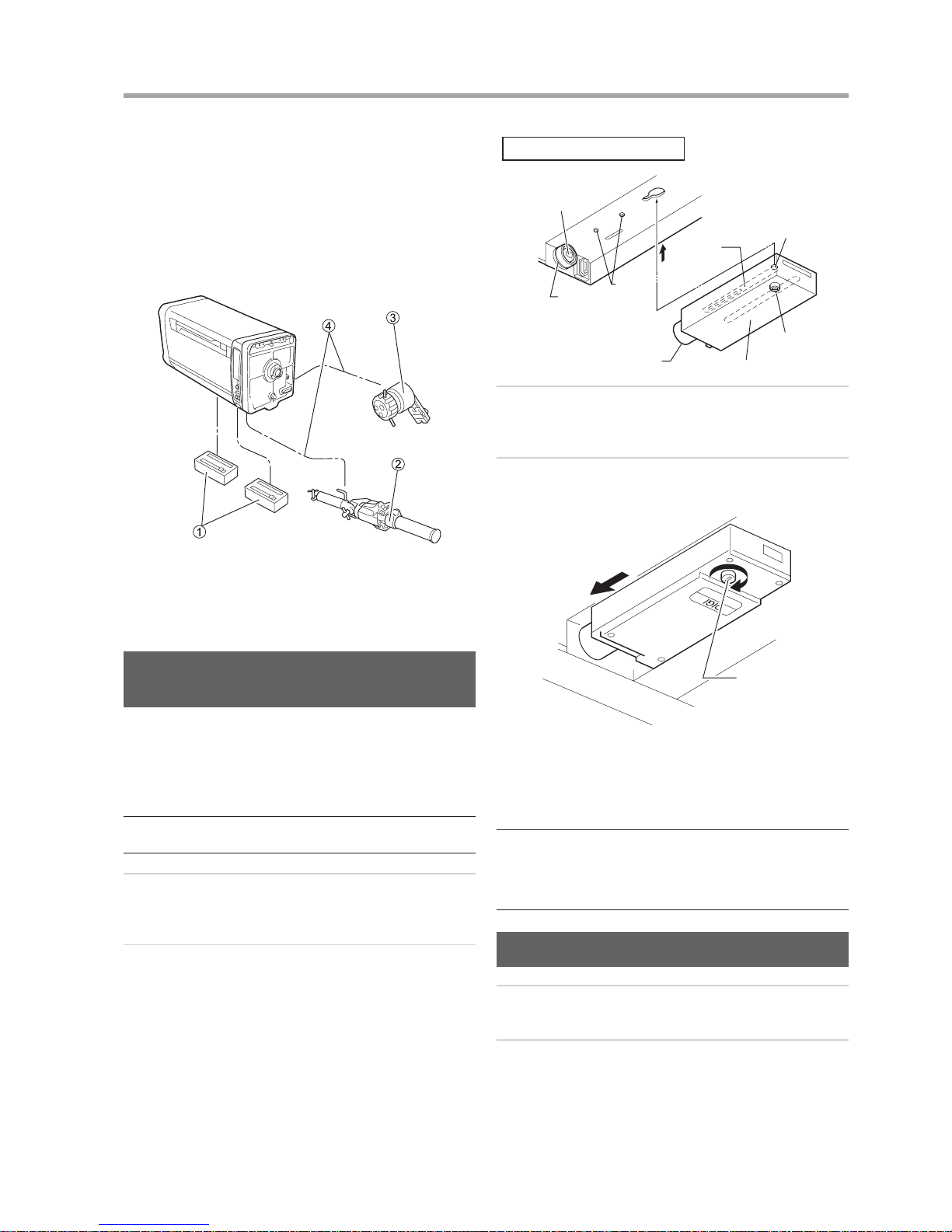
① Servo module
② Zoom servo demand
③ Focus servo demand
④ Demand cable
Mounting the Servo Module onto the
Lens
It is necessary to mount the servo module to the zoom and
focus couplings located in the bottom compartment of the
lens.
* (NOTE)
The same servo module is used for both zoom and focus couplings.
So, it can be mounted on either the zoom or focus coupling.
1
Before mounting a module to the lens, turn the lock
screw of the module counterclockwise until the lock
axis comes out to its a half way of length.
2
Press the module in the direction of arrow “A”, so
that the key pins on the lens are inserted in the key
grooves of the module.
Coupling B
Index Line
(White Line)
Arrow A
Key
Groove
Bottom compartment of the lens
Lock Axis
Lock Screw
Servo Module
Coupling A
Key Pin
3
Mate the coupling A of the module with the coupling
B of the lens. And then, fully push the module in the
direction of arrow “B” until it stops.
4
Finally, turn the lock screw of the module clockwise to
secure it. By using a coin, tighten rmly the lock knob.
Arrow B
Lock Screw
Lock
Next, as the same procedure, install the servo module on
the other joint. It does not matter which is installed rst,
either the zoom or the focus.
* (NOTE)
When mating couplings A and B, push the servo module in
completely, so that the index line (white line) on the circumference
of coupling B is entirely hidden. If index line is not completely
hidden, the servo module may fail to operate, or it may generate
abnormal acoustic noise.
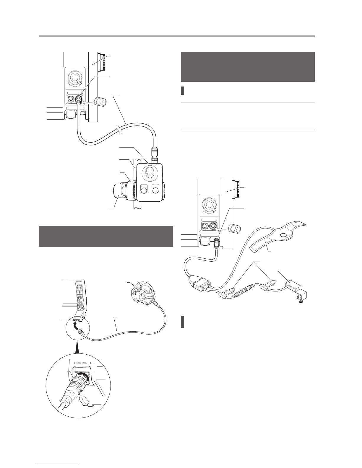
Mounting the Switch Box
1
Mount the switch box to the panhandle of the tripod,
using the attached clamp.
2
Connect the switch box to the lens, using the included
cable.
Page 12
E4
1 HOW TO MOUNT
E5
Switch Box Cable
“SW. BOX” Connector
Lens
Switch Box
Pan Handle
Clamp
Clamp fixing knob
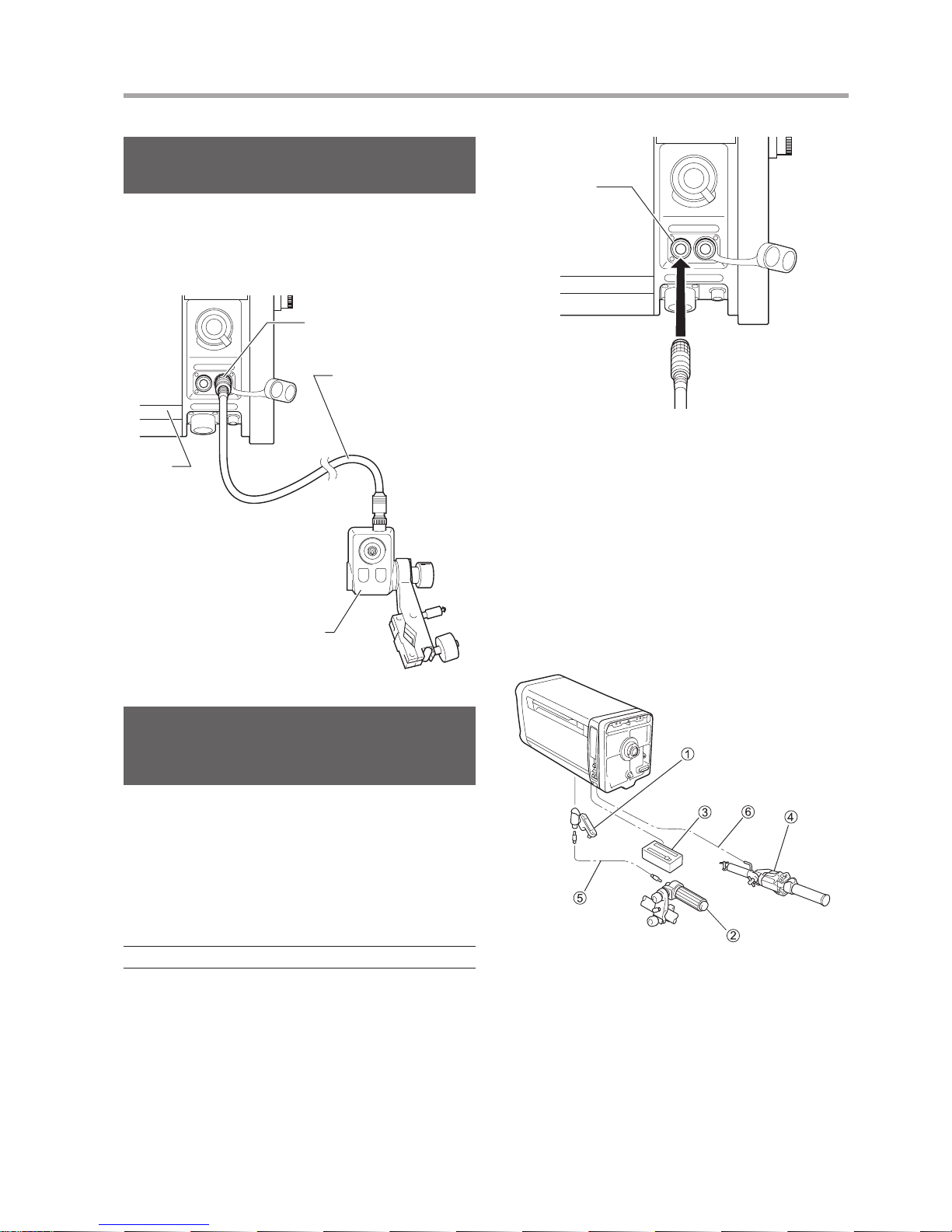
Mounting the AF (Auto Focus) Demand
(Only Models with AF Function)
The AF demand unit is mounted and connected as shown
in the gure below. Follow the procedure in the operation
manual for the demand to mount and connect the demand.
AF Demand
FDJ-P41
Demand Cable
Lens
Fixing
Ring
• This figure shows the
case with the AF demand
FDJ-P41 mounted on the
right side as viewed from
the camera.
Lock
Mounting the Accessories for IS
Operation (Only Models with IS
Function)
Mounting the IS operation unit
1
Plug the connector of the IS operation unit into the
receptacle labeled “AUX” on the left side of the lens
(as viewed from the camera).
2
The IS Indicator unit on the other branch of the cable
comes with an anchoring screw. Mount it to the
location (such as on the edge of the viewnder) where
the ON/OFF status of the LEDs can be observed.
The IS indicator unit is not necessary for the camera
equipped with display function.
Lens
IS Operation Switch
Fixing Belts
IS Indicator Unit
(or Viewnder)
“IS Controller” Connector
Seeing the IS operating statuses in the
viewnder
When using a camera provided with a function for receiving
the signals indicating that the IS function is operating or
stopped from the lens side and displaying this operating
status on its viewnder, it is possible to connect only the IS
Operation Switch and operate it to perform these functions.
Remove the IS indicator unit that is connected partway
along the cable from the IS operation unit.
Page 13
E5
1 HOW TO MOUNT
Connecting Wiper Switch Box
(Option)
When using separately purchased switch box for the
wiper equipped lens, connect it to the lens using the
dedicated cable. (Connection method varies by switch box
specications.)
Lens
“SW. BOX” Connector
Wiper Switch Box
Cable
Wiper Switch Box
(Shapes and connections
vary by specications.)
Connecting the “VIRTUAL” Cable
(Only Models with "VIRTUAL"
Connector)
The lens is equipped with the connector labeled “VIRTUAL”
on its left side (as viewed from the camera). This connector
can be used for connection with an interface to virtual
systems. Zoom, focus and iris signals can be output in three
types of communication data; analog signal, encoder pulse
train and RS-422.
* (NOTE)
Connector location may vary by models.
“VIRTUAL”
Connector
To Virtual System
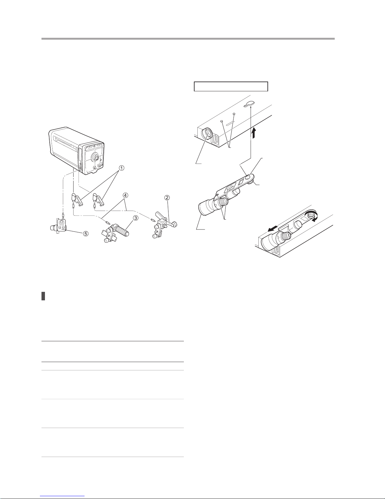
1-3 Mounting the
Accessories for Semiservo Operation
The zoom servo demand and the exible focus control unit
are mounted and connected as shown in the gure below.
When mounting the various demands, refer to the operation
manual for the respective demand.
① Flexible module
② Flexible focus control unit
③ Servo module
④ Zoom servo demand
⑤ Flexible cable
⑥ Demand cable
Page 14
E6
1 HOW TO MOUNT
1-4 Mounting the
Accessories for Manual
Control System
Mount and connect the exible zoom and focus control units
as shown in the gure.
When mounting the various demands, refer to the operation
manual for the respective demand.
① Flexible module
② Flexible zoom control unit
③ Flexible focus control unit
④ Flexible cable
⑤ Switch box unit
Mounting the exible module
It is necessary to mount the exible module to the zoom and
focus couplings located in the bottom compartment of the
lens.
* (NOTE)
The same exible module is used for both zoom and focus
couplings. So, it can be mounted on either the zoom or focus
coupling.
1
Before mounting the module to the lens, turn the lock
screw of the module counterclockwise until the lock
axis comes out to its a half way of length.
2
Press the module in the direction of arrow “A”, so
that the key pins on the lens are inserted in the key
grooves of the module.
3
Mate the coupling A of the module with the coupling
B of the lens. And then, fully push the module in the
direction of arrow “B” until it stops.
4
Finally, turn the lock screw of the module clockwise to
secure it. By using a coin, tighten rmly the lock knob.
Next, as the same procedure, install the exible module
on the other joint. It does not matter which is installed rst,
either the zoom or the focus.
Bottom compartment of the lens
Key Pin
Arrow A
Lock Axis
Lock
Coupling B
Lock Screw
Key Groove
Coupling A
Arrow B
Page 15

E7
2 PREPARATION
2-1 InitializeOperation
(OnlyModelswithaDisplay)
This lens has a built-in encoder for a position sensor of
zoom, iris and focus, and enables high-accuracy control and
advanced for virtual interface. The correct position must be
detected for these functions to operate correctly.
The Auto [ON]/Manual [OFF] setting of initialization can be
set from the information display.
Auto [ON]
The lens is automatically initialized on power-up.
(When in servo mode)
Manual [OFF]
After the power is turned on, position detection is
performed when the lens passes the specic position
(normally near the center) in the course of lens
operation.
* Default setting at factory: OFF
For the detailed setting method, refer to the “Display
OperationManual” at the end of this Operation Manual.
How to detect the position of ZOOM
Initialize
operation
Howtodetecttheposition
ON (Auto)
When the power is turned on, the lens automatically
detects the position. Then, it returns to the position
where it used to be when the power was turned on.
OFF (Manual)
Immediately after the power is turned on, the lens
operates at a temporary position, and the position is
corrected when the lens passes the specic position
and the position is detected.
How to detect the position of FOCUS
Initialize
operation
Demand Howtodetecttheposition
ON (Auto)
Connected
When the power is turned on, the lens
automatically detects the position. Then,
it returns to the position instructed by
command from the demand.
Not
connected
When the power is turned on, the lens
automatically detects the position. Then,
it returns to the position where it used to
be when the power was turned on.
OFF
(Manual)
Connected
When the power is turned on, the lens
automatically detects the position. Then,
it returns to the position instructed by
command from the demand.
Not
connected
The lens does not automatically
detect the position when the demand
is not connected. When the demand
is connected, the lens automatically
detects the position. Then, it returns to
the position instructed by command from
the demand.
Whenpositiondetectionisfailed:
• The position signal sent from the lens to the camera and
its indication on the information display will be incorrect.
Notes
• Iris is always initialized when powered on regardless of
auto mode or manual mode.
• During initialization, lens operation is disabled. After
initialization is completed, the lens returns to the position
where it used to be before initialization. However, if the
lens is operated in the position servo mode, the lens
moves to the currently controlled position.
• The initialization operation can be enabled/disabled on
the information display. When any initialization operation
is changed, turn off then on the power for the changes to
take effect.
The “Initialize Error!” message appears whentheservo
moduleisnotmountedcorrectly, the lens is forcibly
locked, or some other reason.
In such case, check the lens condition, clear the problem,
and then turn off and on the power again.
Initialize Error! message
Initialize
Error!
2-2 BackFocusAdjustment
If the relationship between the image plane of the zoom
lens and that of the television camera is incorrect, the object
goes out of focus when the lens is zoomed. Follow the steps
below to adjust the back focus of the lens.
1
Select an object at an appropriate distance (XJ27xAF/
XJ27x/XJ23x: 3 to 5 m, XJ100xAF/XJ100x/XJ95x/
XJ86xAF/XJ86x/XJ75x/XJ72x/XJ60x: 10 to 15 m
recommended). Use any object with sharp contrast to
facilitate the adjustment work.
2
Set the lens to 1x [status without using an extender].
3
Set the iris fully open.
4
Set the lens to the telephoto angle.
F.B. Adjusting Knob
F.B. Lock Knob
Page 16

E8
2 PREPARATION
E9
5
Bring the object into focus by focus operation.
6
Set the lens to the widest angle.
7
Loosen the F.B. lock knob, and then turn the F.B.
adjusting knob to bring the object into focus.
8
Repeat steps 4 to 7 several times, until the object
is brought into focus at both the widest angle and
telephoto ends.
9
After making sure that the object is in sharp focus,
tighten the F.B. lock knob.
The adjustment procedure is now completed.
2-3 Removing and
Installing the Lens
Shroud
When any electrical setting or adjustment is required,
remove and install the lens shroud following the steps
below.
Fastener type
1
Release the fasteners on both sides of the lens
shroud, then pull the shroud forward to remove from
the lens body.
2
When installing the lens shroud back in place, align
the shroud to the guide rails of the lens body, and then
push the shroud until it stops at the end of the mount.
Press the shroud fasteners near to the end of the
mount side to lock the shroud.
Fastener
Recessed Handle
(Both side of the lens)
Lens Shroud
* (NOTE)
Make sure that the fasteners of the lens shroud are always locked
when it is mounted on the lens.
Knob type
1
Turn the shroud mounting knobs on the bottom of the
lens shroud counterclockwise.
2
Hold two recessed handles on both side of the lens
shroud, and then pull and remove the shroud from the
lens body.
Shroud
mounting knobs
Recessed Handle
(Both side of the lens)
Lens Shroud
3
When putting the lens shroud back on the lens body,
align the shroud to the guide rails of the lens body, and
then push the shroud until it is stopped at the end of
the mount.
Turn the shroud mounting knobs on the bottom
clockwise.
* (NOTE)
With the lens shroud mounted on the lens, check that the shroud
mounting knobs are secured tightly at all times. If these knobs are
not perfectly tight, the lens shroud may work free from the main unit
and drop off when the camera is tilted down.
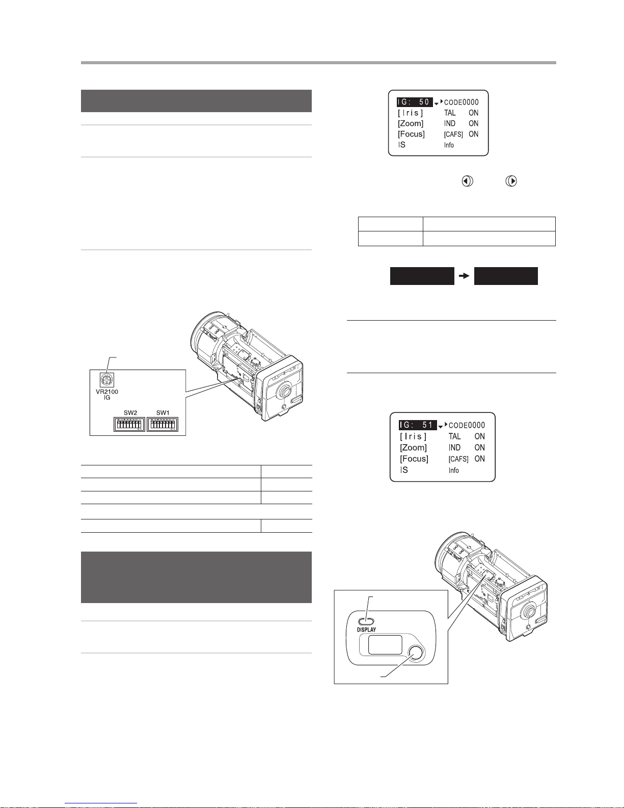
2-4 Iris Gain Adjustment
The iris gain is set to the middle of the adjusting range at
the factory. However, if the iris gain needs to be changed
for some reason, follow the steps below. These steps can
be taken by the trimmer adjustment or on the information
display. (The setting implemented last takes precedence)
* (NOTE)
For other iris adjustment such as iris ends adjustment or video level
adjustment when the extender is used, contact Canon dealer or
your Canon sales representative.
Page 17
E9
2 PREPARATION
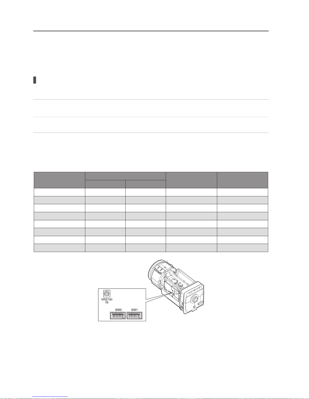
Trimmer Adjustment
1
Remove the lens shroud from the lens body.
2
Check that DIP switch (iris control select switch) is set
to the “OFF” position (refer to the table below).
Depending on the command signals from the camera,
the iris would not be set to auto iris mode although
the switch was set to the “OFF” position. For details,
refer to the “Iris mode” table in 2-5 “Iris Mode Setting
(Option)”.
3
Turn the iris gain adjusting trimmer for the gain
adjustment. To increase the gain, turn the trimmer
clockwise. To decrease the gain, turn the trimmer
counterclockwise.
Iris Gain Adjusting
Trimmer
DIP Switch
IESD/IDSD
XJ100xAF, XJ95x, XJ86xAF, XJ80x, XJ76x, XJ27xAF (SW2) No. 4
XJ100x, XJ86x, XJ75x, XJ72x (SW1) No. 4
XJ60x, XJ27x, XJ23x (SW1) No. 8
IESDA
XJ60x, XJ27x, XJ23x (SW2) No. 4
Making Adjustments on the
Information Display (Only Models
with a Display)
1
Perform “Trimmer Adjustment” steps 1 and 2.
2
Information display operation procedure:
a. Push the DISPLAY switch to bring up the display.
(a)
b. When the screen starts ushing by pushing the
cursor button, move the
(left) or (right)
cursor button until the value to be set appears on
the screen.
Selection item 01 – 99
Function Minimum gain Maximum gain
Default value: 50
I G : 50 I G : 51
(b)
* (NOTE)
• To perform the gain adjustment while checking the iris
operation, set the iris mode of the camera to the [AUTO]
position.
• To determine the maximum gain, set the trimmer at a level
where no hunting occurs.
c. Push the cursor button. This completes the
adjustment.
(c)
For the detailed setting method, refer to the “Display
Operation Manual” at the end of this Operation Manual.
DISPLAY
switch
Information Display
Cursor
button
Page 18
E10
2 PREPARATION
E11
2-5 Iris Mode Setting (Option)
DIP switch (iris control select switch) was set to the “OFF” position at the factory.
See the table below to nd the relationship between the position of the switch and signals.
Iris mode
Iris control and operation depend on the following three signals
1
Enforced auto iris command signal from the camera system (IRIS ENF)
(Some camera models are not capable to provide this signal.)
2
AUTO/REMOTE iris command signal from the camera system (IRIS A/R)
3
Setting position of DIP switch inside the lens body (Refer to the table under “Trimmer Adjustment” on the previous
page.)
(“ON” position: I.LOCAL/“OFF” position: I.CAMERA However, I.LOCAL may not be usable depending on the
specications.)
The table below lists the relationship between these three signals and iris mode.
Position of the DIP switch
Command signal from camera
Iris Control signal from Iris mode
IRIS ENF IRIS A/R
OFF ON Auto Camera Auto iris
OFF ON Remote Camera Remote iris
OFF OFF Auto Camera Auto iris
OFF OFF Remote Camera Remote iris
ON ON Auto Camera Auto iris
ON ON Remote Camera Remote iris
ON OFF Auto Switch box Remote iris
ON OFF Remote Switch box Remote iris
DIP switch
Page 19
E11
2 PREPARATION
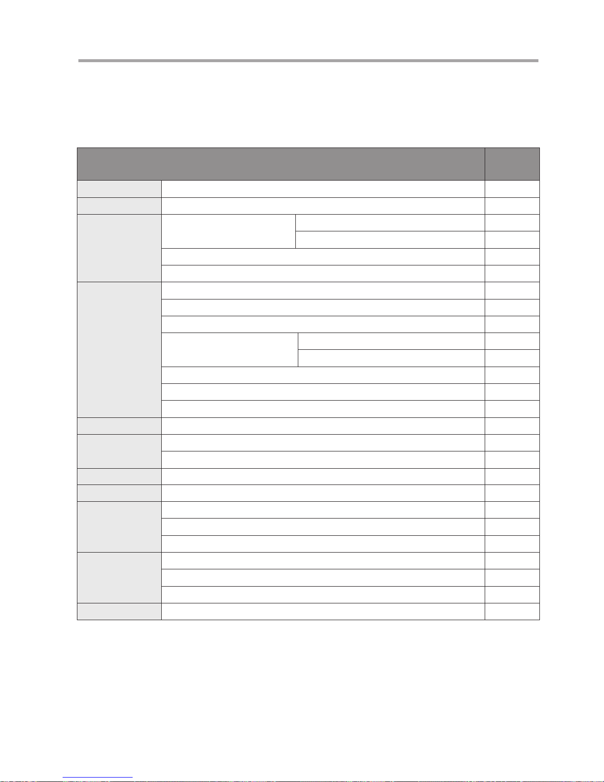
2-6 Setting on the Information Display
The table below shows the functions that can be set from the information display. For the detailed setting method, refer to
the “Display Operation Manual” at the end of this Operation Manual.
Functions that can be set from the information display
Reference
page in
appendixes
Lens name Lens code setting E4
Initialize operation Initialize operation setting E4
Iris control
Iris gain
Setting the auto iris gain E4, E5
Setting the remote iris gain E5
Setting the iris correction to ON/OFF E5
Setting the iris close detection to ON/OFF E6
Zoom control
Setting the zoom servo start characteristics E6
Setting the zoom servo stop characteristics E6
Setting the zoom mechanism end stop characteristics E6
Preset
Setting the zoom servo start characteristics E7
Setting the zoom servo stop characteristics E7
Setting the analog demand curve characteristics E7
CAM mode settings E8
Setting the servo mode type from the zoom demand E8
Focus control Focus demand curve characteristics E9
Tally
Setting the tally lamp ON/OFF E6
Tally lamp light quantity setting E11
Indicator Setting the indicator ON/OFF E8
CAFS Setting the CAFS ON/OFF E9
IS
IS mechanical lock setting E10
IS operation switch setting E10
IS mode setting E10
Other
Encoder output setting E11
Setting the camera serial communication to ON/OFF E11
Adjusting the Camera Fol Voltage E12
Reset operation Reset to default values E1
Page 20

E12
2 PREPARATION
2-7 IncorporableFocus
ServoDemand
(Option)
The optional incorporable focus servo demands are offered
for some types of camera.
1
Remove the lens shroud from the lens.
2
Set the focus demand selection switch to the “CAM”
position.
*(NOTE)
This switch is usually set to the “LENS” position by default.
Focus Damand Characteristics Curve
Selection Switch
(Only models without information display)
Information display
Focus Demand Selection Switch
3
Set the focus demand characteristics curve mode on
the informaiton display. One mode can be selected
among the following three curves. For the detailed
setting method, refer to the “DisplayOperation
Manual” at the end of this Operation Manual. Users of
models without the information display can select the
mode with the focus demand characteristics selection
switch.
STD (Standard mode): The Standard mode has the characteristics
where the relationship between the rotation
amount of the control knob and the moving
amount of the focus lens group is almost
in linear.
FAR (Far mode): The Far mode facilitates focusing on an
object in the far end, by making the far end
curve characteristics gentle to increase the
far end resolution.
This mode is useful when shooting an
object in comparatively far distance in
sports events, for example.
NEAR (Near mode): Contrary to the Far mode, the Near mode
facilitates focusing on an object in the
near end, by making the near end curve
characteristics gentle to increase the near
end resolution.
This mode is useful when shooting an
object in a limited space such as a studio.
Innity
Close
range
Focus position
Knob position
Far
mode
Standard
mode
Near mode
Page 21
E13
3 OPERATION
3-1 Zoom and Focus
Operation
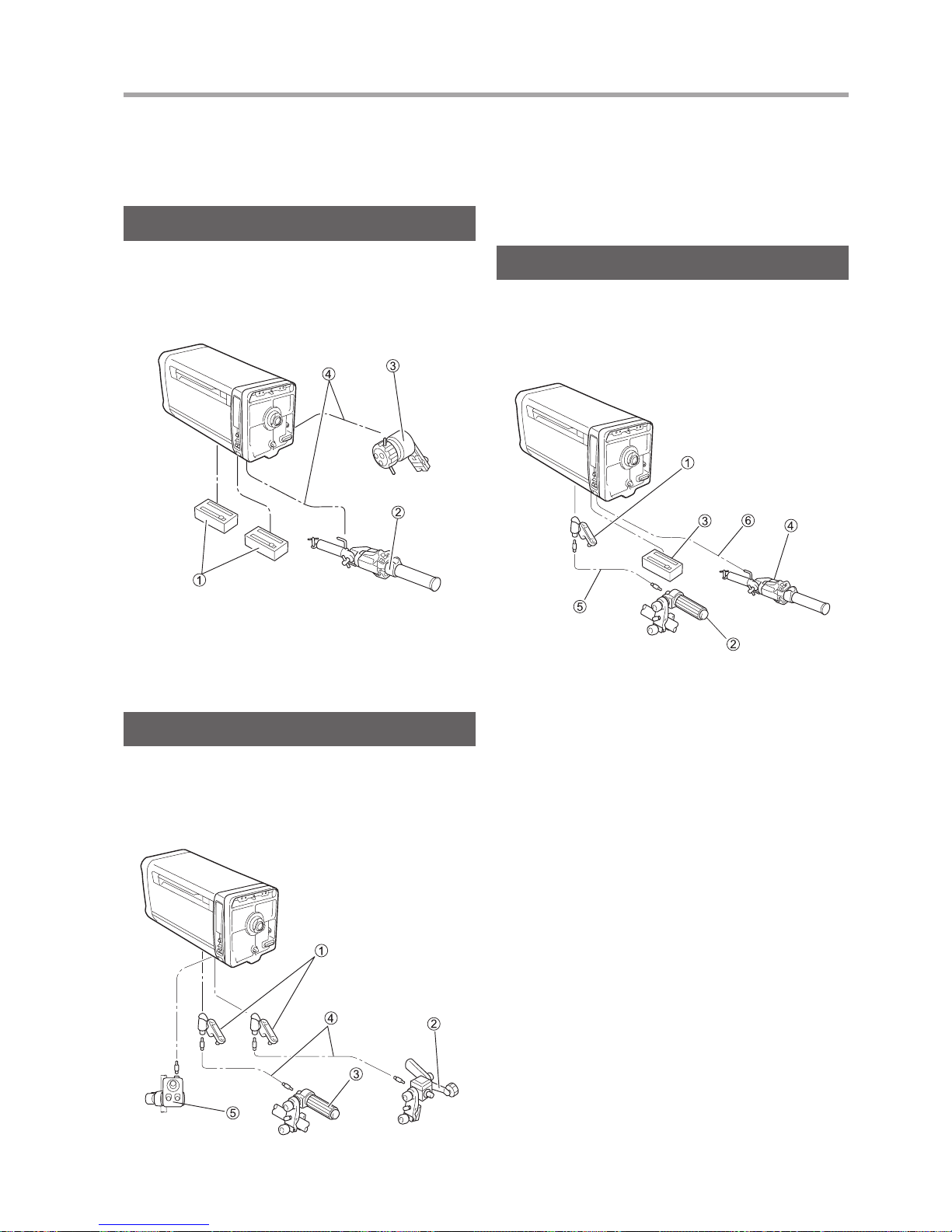
Full-servo System Operation
Zoom and Focus operations are performed based on a
conguration as shown in the gure below.
For the operating procedure, refer to the operation manual
for the respective unit.
① Servo module
② Zoom servo demand
③ Focus servo demand
④ Demand cable
Manual System Operation
Zoom and Focus operations are performed based on a
conguration like that shown in the gure below. For the
operating procedures, refer to the operation manual for the
respective unit.
① Flexible module
② Flexible zoom control unit
③ Flexible focus control unit
④ Flexible cable
⑤ Switch box unit
Semi-servo System Operation
Zoom and Focus operations are performed based on a
conguration like that shown in the gure below.
For the operating procedures, refer to the operation manual
for the respective unit.
① Flexible module
② Flexible focus control unit
③ Servo module
④ Zoom servo demand
⑤ Flexible cable
⑥ Demand cable
Page 22
E14
3 OPERATION
E15
3-2 IrisOperation
Normally, lens iris operation is performed by the position
servo control method using commands from the camera
CCU. Control can be switched between auto iris control and
remote iris control.
The camera operator can also perform remote iris
control using a switch box (special version) as a special
specication.
ControlfromtheCamera
Both automatic and remote iris control are usually operated
from the CCU. (Refer to the camera operation manual on
how to operate.)
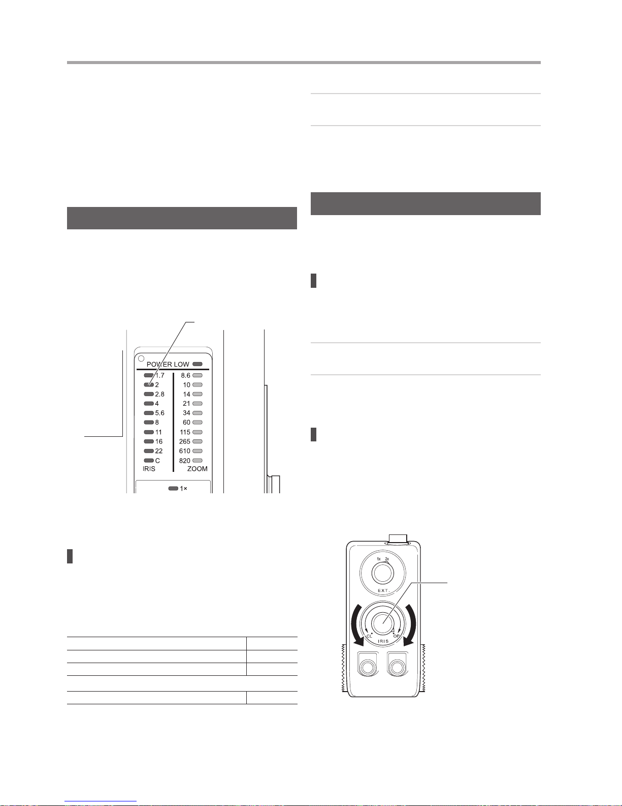
During the shooting, an approximate F number (iris value)
can be checked with the indicator panel on the left side of
the lens, as viewed from the camera.
F Number Indicator
The value indicated by the indicator varies
depending on the model.
Settingtheiriscontrolselectswitch
The DIP switch was set to the “OFF” position (I.CAMERA) at
the factory prior to shipment so that the iris can be operated
from the camera. If the iris operation is disabled, follow the
steps below to check the setting position of DIP switch (refer
to the table below).
IESD/IDSD
XJ100xAF, XJ95x, XJ86xAF, XJ80x, XJ76x, XJ27xAF (SW2) No. 4
XJ100x, XJ86x, XJ75x, XJ72x (SW1) No. 4
XJ60x, XJ27x, XJ23x (SW1) No. 8
IESDA
XJ60x, XJ27x, XJ23x (SW2) No. 4
“OFF” position: Iris operation is enabled from the camera.
“ON” position: Iris operation is enabled from such as switch
box.
1
Remove the lens shroud.
2
Check that DIP switch is set to the “OFF” position. If
the switch is set to “ON” position, change the setting to
the “OFF” position.
ControlfromtheSwitchBox
When a switch box which is capable to control the iris
function of the lens is mounted, the iris function of the lens is
controlled by it.
Settingtheiriscontrolselectswitch
Settings must be performed at the lens side in order for the
iris to be controlled from the switch box. Follow the setting
steps below.
1
Remove the lens shroud.
2
Change the DIP switch setting to the “ON” position
(I.LOCAL).
Controlling
Control the iris by turning the iris control knob as set forth
below.
Turning the knob clockwise:
The iris moves in the opening direction.
Turning the knob counterclockwise:
The iris moves in the closing direction.
Iris Control Knob
As when the iris is to be controlled from the camera, the
approximate F number can be monitored on the indicator
panel.
Page 23

E15
3 OPERATION
*(NOTE)
• See the section “Mounting the Switch Box” (p. E3) for details of
how to mount and connect the switch box.
• Refer to the table “Iris mode” in the section 2-5 “Iris Mode Setting
(Option)” to understand the relationship among the command
signals from camera, iris control device, and the position of the
iris control select switch.
3-3 ExtenderOperation
RemoteOperation
Remotecontrollingfromthezoomservo
demandandswitchbox
Remote extender control can be performed from the zoom
servo demand, switch box, and other accessories.
Remotecontrollingfromthecamera
On the camera equipped with the extender control function,
remote extender control can be performed from the extender
control device mounted on the CCU or the camera head.
Refer to the operation manual for the respective TV camera.
*(NOTE)
• When the zoom servo demand or the switch box is used together,
the extender is controlled by the command from the last operated
device.
• The extender(s) can be selected by the extender manual control
knob even during remote control.
ManualOperation
In case of emergency such as when the remote extender
control is failed, or when any of above three extender control
devices is unavailable, the extender(s) can be controlled
manually.
Controlling
Manually turn the extender manual control knob to operate
the extender(s).
The current extender position is shown by the LED on the
indicator. (All the extender LEDs on the indicator panel
remain off while operations are being performed.)
Extender Manual Control
Knob
3-4 OperatingtheAF(Auto
Focus)Function
(OnlyModelswithAFFunction)
An AF demand is necessary to operate the AF function.
For more information about AF operation and AF function
settings, please refer to the AF demand operation manual.
AFfunctionnotes
• Focusing using the AF may not be possible when shooting
the following types of subjects.
ExamplesofobjectsdifculttofocususingtheAF
• Subjects with low contrast: Blue sky or a singlecolored, at surface
• Subjects having particularly fast movement
• Subjects at night or dark locations
• The back focus of the lens may change slightly due to
variations in the ambient temperature. To obtain the best
auto focus performance, it is advisable to conrm that the
back focus is appropriate.
3-5 OperatingtheIS
Function
(OnlyModelswithISFunction)
KnowingtheBasicOperation
If the image shakes noticeably, turn on the IS function to
stabilize the image.
Some IS characteristics may cause the image to move in
an unnatural manner and not as intended when panned
or tilted quickly. This is because the panning or tilting
motion is mis-detected as a vibration, and the IS function is
activated to correct it. Select the operating characteristics
(STD) so that unnatural movements from panning and
tilting are minimized. In addition, note that image stabilizing
performance may not be fully delivered during the warming
up time.
SettingtheISPreferences
During shooting, the IS function can be turned ON/OFF
using the IS operation switch or other accessory.
UsingtheISoperationswitch
Press, release, or hold down the center button to control the
IS function.
Page 24
E16
3 OPERATION
E17
IS Operation Switch
UsingtheaccessorieswithISoperation
switchfunction
When using an accessory with IS operation function, refer to
the operating instructions of the accessory.
*(NOTE)
The IS function activated by pressing, releasing or holding down the
button varies according to the lens setting.
SettingtheISoperationswitchmode
(Formodelswithoutadisplay)
<SelectingALT/MON>
ALT
The IS function state alternates between “IS SW-ON”
and “IS SW-OFF” each time the IS operation switch
is pressed.
MON
The IS function state is momentarily set to “IS SWON” while the IS operation switch is held down.
“ALT” is set by default.
ALT/MON selection.......... ALT : Set No.7 to OFF.
MON : Set No.7 to ON.
(At the factory, No.7 was set to the OFF position.)
<SelectingSW*/OFF>
Select the IS operation mode (OFF: IS STD.) when IS
operation switch is OFF.
When SW* is selected:
When the IS operation switch is ON, the IS function operates at the
characteristics preset at the IS selector switches (it stops when OFF
is selected). When the IS operation switch is OFF, the IS function
operates at the standard characteristics (STD).
When OFF is selected:
When the IS operation switch is ON, the IS function operates at the
characteristics preset at the IS selector switches (it stops when OFF is
selected). (The function operates for both the H and V directions.)
When the IS operation switch is OFF, the IS function stops.
SW * / OFF selection....... SW * : Set No.6 to OFF.
SW OFF : Set No.6 to ON.
(At the factory, No.6 was set to the ON position.)
1234567
8
O
N
1234567
8
O
N
IRIS AUTO
GAIN
TALLY
BRIGHT SW2
ANALOG AMP
SW1
L. CODE
IE MANU.
I. LOCAL
SW
㸨
/OFF
ALT/MON
POWER OFF
/ON
/ON
ON
TALLY/IND.
ON OFF
ON/OFF
DIGITAL AMP
SW4
CAFS OFF
ON
ձ 㹼մ
յ
ն
շ
ո
ձ
ղ
մ
ճ
յ
ON
ON
IS MODEL ONLY
SW*/OFF -/ON
ALT/MON -/ON
POWER OFF ON
IS MODEL ONLY
DIP Switch 1
No.1 to No.8
*(NOTE)
DIP switch 1 No. 8 is the IS main power switch. Normally, the switch
is kept at the OFF position.
(Formodelswithadisplay)
Change the setting on the information display.
For details on the information display, refer to the “Display
OperationManual” at the end of this Operation Manual.
Information Display
SettingtheImageStabilizing
DirectionandCharacteristics
IS Horizontal
Direction Selector
Switch
IS Vertical
Direction
Selector
Switch
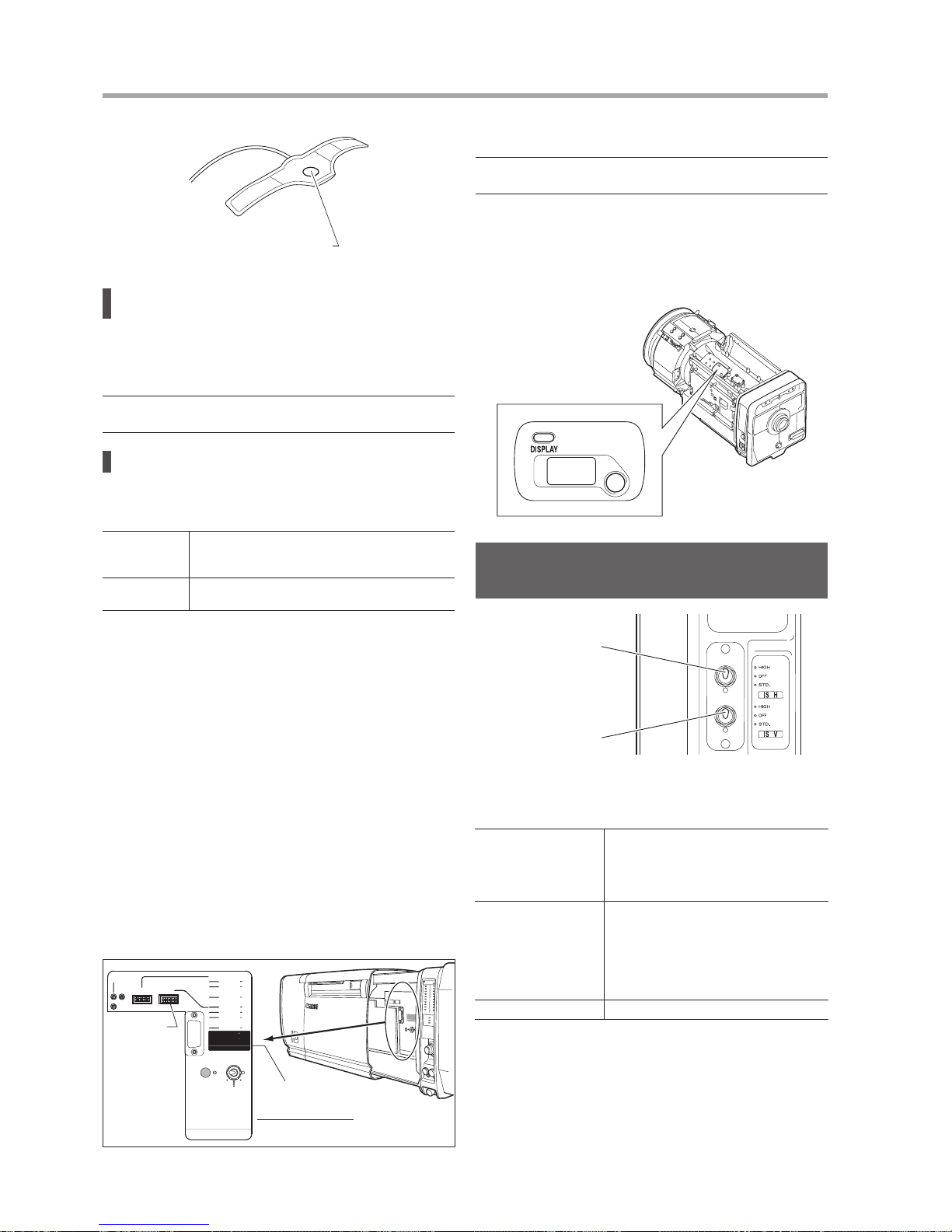
To select one of the following modes, operate the IS
horizontal (or vertical) direction selector switch.
Standard characteristics
(STD.)
This mode minimizes unnatural movements
by implementing special processing for
the low-frequency shaking caused by slow
camera work and allows smooth operation
during regular camera operation.
Maximum
characteristics (HIGH)
This item is set to ensure that the shaking
in all the frequency bands is stabilized
at the maximum characteristics. If lowfrequency shaking is a concern with
stationary shots, the anti-vibration effect
is enhanced by selecting the maximum
characteristics.
Stop (OFF) This stops the IS function.
Page 25
E17
3 OPERATION
IS Indicator Unit
LED
Checking with the viewnder
The IS function activation state can also be checked with
the viewnder, if the camera is equipped with the viewnder
capable of indicating it.
For details, refer to the operation manual for the camera.
Advanced settings of IS function
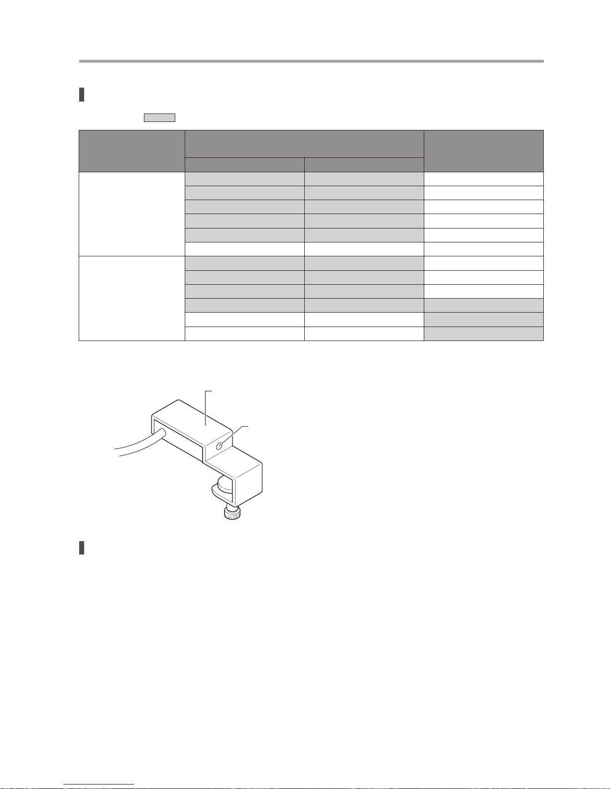
Shaded sections indicate that the IS indicator unit LED is lighted.
IS mode setting
IS SW-ON
(Switch is pressed when set to MON)
→ Selector switch status is applied
IS SW-OFF
(Switch is not pressed when
set to MON)
H V
OFF
Hi Hi OFF
STD Hi OFF
OFF Hi OFF
STD STD OFF
OFF STD OFF
OFF OFF OFF
STD
Hi Hi STD
STD Hi STD
OFF Hi STD
STD STD STD
STD OFF STD
Hi OFF STD
* When the power is turned on, the IS function is in IS SW-ON state if the IS operation switch mode is set to “ALT”, and in IS SW-OFF state if set to
“MON”.
Page 26
E18
E19
4 OtherFunctionsandOptions
4-1 Checking for Low
Power
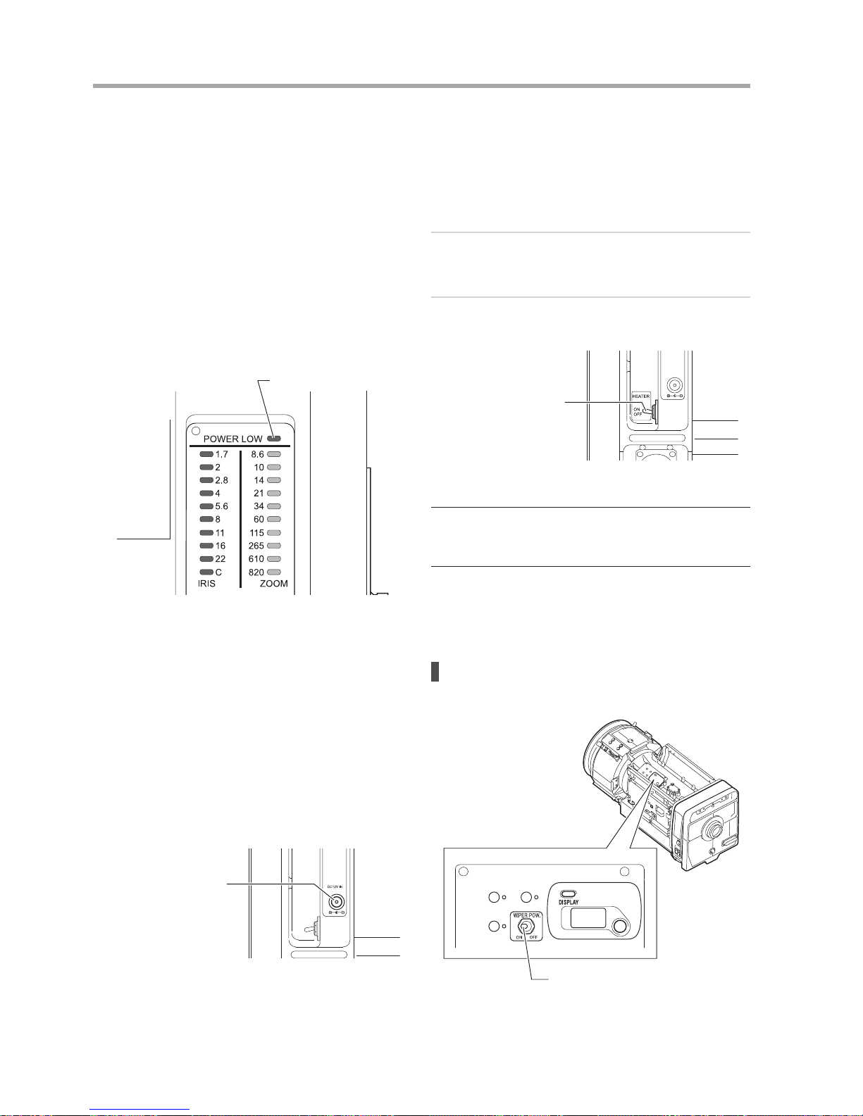
The power low LED, used to indicate low power supply
warning, is provided on the indicator panel at the left side of
the lens, as viewed from the camera.
According to the supplied voltage, LED indicates:
Lit red: 10V or less
Off: Supplies sufcient voltage
So, when the LED is lit red, countermeasures to raise the
supply voltage to 10.5V or above is necessary. Otherwise,
the lens may malfunction.
POWER LOW LED
4-2 Using an External
Power Source
An external power input jack is provided at the right
side of the lens, as viewed from the camera. In case the
combination of portable camera and the lens with semi
or full servo operation, 12V DC (11-17V DC) should be
supplied to the lens through this jack since portable camera
does not have enough power consumption to drive semi or
full servo operation.
External Power Input Jack
Use a plug complying with EIAJ RC5320A TYPE4
specications.
4-3 Heater System (Option)
The heater system for warming up the lens to prevent
clouding inside the lens can be mounted on the lens. The
heater system is operated as follows.
1
Set the heater ON/OFF switch, which is located on the
right side of the lens as seen from the camera, to the
ON position.
2
To shut down the heater, set the heater ON/OFF
switch to the OFF position.
Heater ON/OFF Switch
* (NOTE)
A great deal of power is consumed when the heater switch is ON.
For this reason, the circuitry is designed to disable servo zoom
operations and servo focus operations.
To perform servo operations, stop using the heater.
4-4 Wiper System (Option)
Checking the wiper power
Check that the power switch of the wiper is set to “ON”.
Wiper Power Switch
Page 27
E19
4 Other Functions and Options
Wiper operation varies according to the mounted
accessories. Refer to the operation manual of the accessory
to use.
* (NOTE)
• Do not operate the wiper with dust, oil, foreign obstacles stained
on the glass surface. Otherwise, the glass may be damaged.
Completely clean the glass before operation.
• If the wiper is operated in the low-temperature environment or for
wiping snow, condensation may form on the glass.
• Do not operate the wiper in a dry condition without moisture.
Otherwise, rubber blade deterioration or incomplete wiping may
result.
• Replace the rubber blade when worn, deformed, or damaged, or
when incomplete wiping occurred. Contact your Canon dealer.
• To use the wiper manually, set the power switch of the wiper to
“OFF”.
Do not manually use the wiper while it is turned “ON”.
4-5 Nitrogen Gas Filling
(Option)
To prevent fog or condensation on the internal surface of the
lens, you can ll the lens barrel with nitrogen gas.
Nitrogen gas should be relled at the periodic overhaul, and
before the critical event.
* (NOTE)
To rell nitrogen gas, gas canister and lling tool are required.
Contact your Canon dealer or your Canon sales representative.
4-6 Zoom Control Selecting
Switch
(Only XJ27x AF and XJ27x)
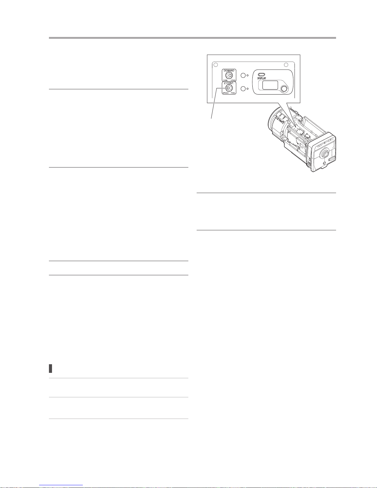
Either the speed servo or position servo can be set as the
servo system from the analog zoom demand. This setting is
performed using the zoom control selecting switch.
Setting steps
1
Remove the lens shroud from the lens body.
2
Set to the servo type using the zoom control selecting
switch.
3
Upon completion of the adjustment, mount the lens
shroud on the lens body.
Zoom Control Selecting Switch
“SPEED” position (left side):
Speed servo (default)
“POS.” position (right side):
Position servo
* (NOTE)
• Similar setting options to the zoom control selecting switch are
also equipped on the information display, however only the status
of the servo system is reected on the display. For that reason,
the setting can not be performed on the information display.
• With “POS.” selected, operation can not be performed from the
digital zoom demand.
Page 28
E20
E21
5 SPECIFICATIONS
■■IESD/IESDA
XJ100x9.3B■AF XJ100x9.3B
4:3■mode
16:9
■mode 4:3■mode
16:9
■mode
Focal Length
1.0x 9.3–930 mm
2.0x 18.6–1860 mm
Zoom Ratio 100×
Maximum Relative
Aperture
1.0x
1:1.7 (at 9.3–296 mm)
1:4.7 (at 930 mm)
2.0x
1:3.4 (at 18.6–592 mm)
1:9.4 (at 1860 mm)
Image Format
8.8 × 6.6 mm
(Diagonal 11 mm)
9.6 × 5.4 mm
(Diagonal 11 mm)
8.8 × 6.6 mm
(Diagonal 11 mm)
9.6 × 5.4 mm
(Diagonal 11 mm)
Angular
Field of
View
Wide
1.0x 50.6º × 39.1º (at 9.3 mm) 54.6º × 32.4º (at 9.3 mm) 50.6º × 39.1º (at 9.3 mm) 54.6º × 32.4º (at 9.3 mm)
2.0x 26.6º × 20.1º (at 18.6 mm) 28.9º × 16.5º (at 18.6 mm) 26.6º × 20.1º (at 18.6 mm) 28.9º × 16.5º (at 18.6 mm)
Tele
1.0x 0.54º × 0.41º (at 930 mm) 0.59º × 0.33º (at 930 mm) 0.54º × 0.41º (at 930 mm) 0.59º × 0.33º (at 930 mm)
2.0x 0.27º × 0.20º (at 1860 mm) 0.30º × 0.17º (at 1860 mm) 0.27º × 0.20º (at 1860 mm) 0.30º × 0.17º (at 1860 mm)
Minimum Object Distance
(M.O.D.)
3.0 m (from lens vertex)
Object
Dimensions
at M.O.D.
Wide
1.0x
253.9 ×
190.4 cm (at 9.3 mm)
276.4 × 155.5 cm (at 9.3 mm) 253.9 ×
190.4 cm (at 9.3 mm)
276.4 × 155.5 cm (at 9.3 mm)
2.0x
127.0 ×
95.2 cm (at 18.6 mm)
138.2 × 77.8 cm (at 18.6 mm) 127.0 ×
95.2 cm (at 18.6 mm)
138.2 × 77.8 cm (at 18.6 mm)
Tele
1.0x 2.54 ×
1.90 cm (at 930 mm)
2.76 ×
1.56 cm (at 930 mm)
2.54 × 1.90 cm
(at 930 mm)
2.76 × 1.56 cm
(at 930 mm)
2.0x
1.27 ×
0.95 cm (at 1860 mm)
1.38 × 0.78 cm (at 1860 mm) 1.27 ×
0.95 cm (at 1860 mm)
1.38 × 0.78 cm (at 1860 mm)
Zoom Speed 0.6 ± 0.1s Max.
Focus Speed 0.8 ± 0.1s Max.
Iris Speed 0.8 ± 0.15s 0.8 ± 0.1s
Mount B4
Input Voltage DC12V (DC10 to 17V)
Power Consumption 24W Max.
Operating Temperature -20°C to +45°C
Dimensions See attached drawing.
Flange back See attached drawing.
Page 29
E21
5 SPECIFICATIONS
XJ95x8.6B XJ86x13.5B
4:3■mode
16:9
■mode 4:3■mode
16:9
■mode
Focal Length
1.0x 8.6–820 mm 13.5–1161 mm
2.0x 17.2–1640 mm 27–2322 mm
Zoom Ratio 95× 86×
Maximum Relative
Aperture
1.0x
1:1.7 (at 8.6–340 mm)
1:4.1 (at 820 mm)
1:2.4 (at 13.5–480 mm)
1:5.8 (at 1161 mm)
2.0x
1:3.4 (at 17.2–680 mm)
1:8.2 (at 1640 mm)
1:4.8 (at 27–960 mm)
1:11.6 (at 2322 mm)
Image Format
8.8 × 6.6 mm
(Diagonal 11 mm)
9.6 × 5.4 mm
(Diagonal 11 mm)
8.8 × 6.6 mm
(Diagonal 11 mm)
9.6 × 5.4 mm
(Diagonal 11 mm)
Angular
Field of
View
Wide
1.0x 54.2º × 42.0º (at 8.6 mm) 58.3º × 34.9º (at 8.6 mm) 36.1º × 27.5º (at 13.5 mm) 39.1º × 22.6º (at 13.5 mm)
2.0x 28.7º × 21.7º (at 17.2 mm) 31.2º × 17.8º (at 17.2 mm) 18.5º × 13.9º (at 27 mm) 20.2º × 11.4º (at 27 mm)
Tele
1.0x 0.61º × 0.46º (at 820 mm) 0.67º × 0.38º (at 820 mm)
0.43º × 0.33º (at 1161 mm) 0.47º × 0.27º (at 1161 mm)
2.0x
0.31º × 0.23º (at 1640 mm) 0.34º × 0.19º (at 1640 mm) 0.22º × 0.16º (at 2322 mm) 0.24º × 0.13º (at 2322 mm)
Minimum Object Distance
(M.O.D.)
3.0 m (from lens vertex)
Object
Dimensions
at M.O.D.
Wide
1.0x
274.1 × 205.6 cm (at 8.6 mm) 298.1 × 167.7 cm (at 8.6 mm) 181.7 × 136.3 cm (at 13.5 mm) 198.2 × 111.5 cm (at 13.5 mm)
2.0x
137.1 × 102.8 cm (at 17.2 mm) 149.1 × 83.9 cm (at 17.2 mm)
90.9 × 68.2 cm
(at 27 mm) 99.1 × 55.7 cm (at 27 mm)
Tele
1.0x 3.0 × 2.3 cm (at 820 mm) 3.2 × 1.8 cm (at 820 mm) 2.1 × 1.6 cm (at 1161 mm) 2.3 × 1.3 cm (at 1161 mm)
2.0x 1.5 × 1.2 cm (at 1640 mm) 1.6 × 0.9 cm (at 1640 mm) 1.1 × 0.8 cm (at 2322 mm) 1.2 × 0.7 cm (at 2322 mm)
Zoom Speed 0.6 ± 0.1s Max.
Focus Speed 0.8 ± 0.1s Max.
Iris Speed 0.8 ± 0.15s 0.8 ± 0.1s
Mount B4
Input Voltage DC12V (DC10 to 17V)
Power Consumption 24W Max.
Operating Temperature -20°C to +45°C
Dimensions See attached drawing.
Flange back See attached drawing.
Page 30
E22
5 SPECIFICATIONS
E23
XJ86x9.3B■AF XJ86x9.3B
4:3■mode
16:9
■mode 4:3■mode
16:9
■mode
Focal Length
1.0x 9.3–800 mm
2.0x 18.6–1600 mm
Zoom Ratio 86×
Maximum Relative
Aperture
1.0x
1:1.7 (at 9.3–340 mm)
1:4.0 (at 800 mm)
2.0x
1:3.4 (at 18.6–680 mm)
1:8.0 (at 1600 mm)
Image Format
8.8 × 6.6 mm
(Diagonal 11 mm)
9.6 × 5.4 mm
(Diagonal 11 mm)
8.8 × 6.6 mm
(Diagonal 11 mm)
9.6 × 5.4 mm
(Diagonal 11 mm)
Angular
Field of
View
Wide
1.0x 50.6º × 39.1º (at 9.3 mm) 54.6º × 32.4º (at 9.3 mm) 50.6º × 39.1º (at 9.3 mm) 54.6º × 32.4º (at 9.3 mm)
2.0x 26.6º × 20.1º (at 18.6 mm) 28.9º × 16.5º (at 18.6 mm) 26.6º × 20.1º (at 18.6 mm) 28.9º × 16.5º (at 18.6 mm)
Tele
1.0x 0.63º × 0.47º (at 800 mm) 0.69º × 0.39º (at 800 mm) 0.63º × 0.47º (at 800 mm) 0.69º × 0.39º (at 800 mm)
2.0x 0.32º × 0.24º (at 1600 mm) 0.34º × 0.19º (at 1600 mm) 0.32º × 0.24º (at 1600 mm) 0.34º × 0.19º (at 1600 mm)
Minimum Object Distance
(M.O.D.)
3.0 m (from lens vertex)
Object
Dimensions
at M.O.D.
Wide
1.0x
253.9 × 190.4 cm (at 9.3 mm) 276.4 × 155.5 cm (at 9.3 mm) 253.9 × 190.4 cm (at 9.3 mm) 276.4 × 155.5 cm (at 9.3 mm)
2.0x
127.0 × 95.2 cm (at 18.6 mm) 138.2 × 77.8 cm (at 18.6 mm) 127.0 × 95.2 cm (at 18.6 mm) 138.2 × 77.8 cm (at 18.6 mm)
Tele
1.0x 3.0 × 2.2 cm (at 800 mm) 3.2 × 1.8 cm (at 800 mm)
3.0 × 2.2 cm
(at 800 mm)
3.2 × 1.8 cm
(at 800 mm)
2.0x 1.5 × 1.1 cm (at 1600 mm) 1.6 × 0.9 cm (at 1600 mm)
1.5 × 1.1 cm
(at 1600 mm)
1.6 × 0.9 cm
(at 1600 mm)
Zoom Speed 0.6 ± 0.1s Max.
Focus Speed 0.8 ± 0.1s Max.
Iris Speed 0.8 ± 0.15s 0.8 ± 0.1s
Mount B4
Input Voltage DC12V (DC10 to 17V)
Power Consumption 24W Max.
Operating Temperature -20°C to +45°C
Dimensions See attached drawing.
Flange back See attached drawing.
Page 31
E23
5 SPECIFICATIONS
XJ80x8.8B XJ76x9B
4:3 mode
16:9
mode 4:3 mode
16:9
mode
Focal Length
1.0x 8.8–710 mm 9–690 mm
2.0x 17.6–1420 mm 18–1380 mm
Zoom Ratio 80× 76×
Maximum Relative
Aperture
1.0x
1:1.7 (at 8.8–340 mm)
1:3.55 (at 710 mm)
1:1.7 (at 9–340 mm)
1:3.45 (at 690 mm)
2.0x
1:3.4 (at 17.6–680 mm)
1:7.1 (at 1420 mm)
1:3.4 (at 18–680 mm)
1:6.9 (at 1380 mm)
Image Format
8.8 × 6.6 mm
(Diagonal 11 mm)
9.6 × 5.4 mm
(Diagonal 11 mm)
8.8 × 6.6 mm
(Diagonal 11 mm)
9.6 × 5.4 mm
(Diagonal 11 mm)
Angular
Field of
View
Wide
1.0x 53.1º × 41.1º (at 8.8 mm) 57.2º × 34.1º (at 8.8 mm) 52.1º × 40.3º (at 9 mm) 56.1º × 33.4º (at 9 mm)
2.0x 28.1º × 21.2º (at 17.6 mm) 30.5º × 17.4º (at 17.6 mm) 27.5º × 20.8º (at 18 mm) 29.9º × 17.1º (at 18 mm)
Tele
1.0x 0.71º × 0.53º (at 710 mm) 0.77º × 0.44º (at 710 mm) 0.73º × 0.55º (at 690 mm) 0.80º × 0.45º (at 690 mm)
2.0x 0.36º × 0.27º (at 1420 mm) 0.39º × 0.22º (at 1420 mm) 0.37º × 0.27º (at 1380 mm) 0.40º × 0.22º (at 1380 mm)
Minimum Object Distance
(M.O.D.)
3 m (from lens vertex)
Object
Dimensions
at M.O.D.
Wide
1.0x
266.8 × 200.1 cm (at 8.8 mm) 290.0 × 163.1 cm (at 8.8 mm) 259.9 × 194.9 cm (at 9 mm) 282.4 × 158.9 cm (at 9 mm)
2.0x
133.4 × 100.1 cm (at 17.6 mm) 145.0 × 81.6 cm (at 17.6 mm) 130.0 × 97.5 cm (at 18 mm) 141.2 × 79.5 cm (at 18 mm)
Tele
1.0x 3.4 × 2.6 cm (at 710 mm) 3.7 × 2.1 cm (at 710 mm)
3.5 × 2.6 cm
(at 690 mm)
3.8 × 2.1 cm
(at 690 mm)
2.0x 1.7 × 1.3 cm (at 1420 mm) 1.9 × 1.1 cm (at 1420 mm)
1.8 × 1.3 cm
(at 1380 mm)
1.9 × 1.1 cm
(at 1380 mm)
Zoom Speed 0.6 ± 0.1s Max.
Focus Speed 0.8 ± 0.1s Max.
Iris Speed 0.8 ± 0.15s
Mount B4
Input Voltage DC12V (DC10 to 17V)
Power Consumption 24W Max.
Operating Temperature -20°C to +45°C
Dimensions See attached drawing.
Flange back See attached drawing.
Page 32
E24
5 SPECIFICATIONS
E25
XJ75x9.3B XJ72x9.3B
4:3■mode
16:9
■mode 4:3■mode
16:9
■mode
Focal Length
1.0x 9.3–700 mm 9.3–675 mm
2.0x 18.6–1400 mm 18.6–1350 mm
Zoom Ratio 75× 72×
Maximum Relative
Aperture
1.0x
1:1.7 (at 9.3–331 mm)
1:3.6 (at 700 mm)
1:1.7 (at 9.3–333 mm)
1:3.45 (at 675 mm)
2.0x
1:3.4 (at 18.6–662 mm)
1:7.2 (at 1400 mm)
1:3.4 (at 18.6–666 mm)
1:6.9 (at 1350 mm)
Image Format
8.8 × 6.6 mm
(Diagonal 11 mm)
9.6 × 5.4 mm
(Diagonal 11 mm)
8.8 × 6.6 mm
(Diagonal 11 mm)
9.6 × 5.4 mm
(Diagonal 11 mm)
Angular
Field of
View
Wide
1.0x 50.6º × 39.1º (at 9.3 mm) 54.6º × 32.4º (at 9.3 mm) 50.6º × 39.1º (at 9.3 mm) 54.6º × 32.4º (at 9.3 mm)
2.0x 26.6º × 20.1º (at 18.6 mm) 28.9º × 16.5º (at 18.6 mm) 26.6º × 20.1º (at 18.6 mm) 28.9º × 16.5º (at 18.6 mm)
Tele
1.0x 0.72º × 0.54º (at 700 mm) 0.79º × 0.44º (at 700 mm) 0.75º × 0.56º (at 675 mm) 0.81º × 0.46º (at 675 mm)
2.0x 0.36º × 0.27º (at 1400 mm) 0.39º × 0.22º (at 1400 mm) 0.37º × 0.28º (at 1350 mm) 0.41º × 0.23º (at 1350 mm)
Minimum Object Distance
(M.O.D.)
2.8 m (from lens vertex)
Object
Dimensions
at M.O.D.
Wide
1.0x
234.3 × 175.7 cm (at 9.3 mm) 255.6 × 143.8 cm (at 9.3 mm) 234.3 × 175.7 cm (at 9.3 mm) 255.6 × 143.8 cm (at 9.3 mm)
2.0x
117.2 × 87.9 cm (at 18.6 mm) 127.9 × 71.9 cm (at 18.6 mm) 117.2 × 87.9 cm (at 18.6 mm) 127.9 × 71.9 cm (at 18.6 mm)
Tele
1.0x 3.2 × 2.4 cm (at 700 mm) 3.4 × 1.9 cm (at 700 mm)
3.3 × 2.5 cm
(at 675 mm)
3.6 × 2.0 cm
(at 675 mm)
2.0x 1.6 × 1.2 cm (at 1400 mm) 1.8 × 1.0 cm (at 1400 mm)
1.7 × 1.3 cm
(at 1350 mm)
1.8 × 1.0 cm
(at 1350 mm)
Zoom Speed 0.6 ± 0.1s Max.
Focus Speed 0.8 ± 0.1s Max.
Iris Speed 0.8 ± 0.1s
Mount B4
Input Voltage DC12V (DC10 to 17V)
Power Consumption 24W Max.
Operating Temperature -20°C to +45°C
Dimensions See attached drawing.
Flange back See attached drawing.
Page 33
E25
5 SPECIFICATIONS
XJ60x9B XJ27x6.5B■AF
4:3■mode
16:9
■mode 4:3■mode
16:9
■mode
Focal Length
1.0x 9–540 mm 6.5–180 mm
2.0x 18–1080 mm 13–360 mm
Zoom Ratio 60× 27×
Maximum Relative
Aperture
1.0x
1:1.7 (at 9–306 mm)
1:3.0 (at 540 mm)
1:1.5 (at 6.5–123 mm)
1:2.2 (at 180 mm)
2.0x
1:3.4 (at 18–612 mm)
1:6.0 (at 1080 mm)
1:3.0 (at 13–246 mm)
1:4.4 (at 360 mm)
Image Format
8.8 × 6.6 mm
(Diagonal 11 mm)
9.6 × 5.4 mm
(Diagonal 11 mm)
8.8 × 6.6 mm
(Diagonal 11 mm)
9.6 × 5.4 mm
(Diagonal 11 mm)
Angular
Field of
View
Wide
1.0x 52.1º × 40.3º (at 9 mm) 56.1º × 33.4º (at 9 mm) 68.2º × 53.8º (at 6.5 mm) 72.9º × 45.1º (at 6.5 mm)
2.0x 27.5º × 20.8º (at 18 mm) 29.9º × 17.1º (at 18 mm) 37.4º × 28.5º (at 13 mm) 40.5º × 23.5º (at 13 mm)
Tele
1.0x 0.93º × 0.70º (at 540 mm) 1.02º × 0.57º (at 540 mm) 2.8º × 2.1º (at 180 mm) 3.1º × 1.7º (at 180 mm)
2.0x 0.47º × 0.35º (at 1080 mm) 0.51º × 0.29º (at 1080 mm) 1.4º × 1.1º (at 360 mm) 1.5º × 0.9º (at 360 mm)
Minimum Object Distance
(M.O.D.)
2.8 m (from lens vertex) 0.6 m (from lens vertex)
Object
Dimensions
at M.O.D.
Wide
1.0x
243.8 × 182.9 cm (at 9 mm) 265.1 × 149.1 cm (at 9 mm) 97.0 × 72.8 cm (at 6.5 mm) 106.1 × 59.7 cm (at 6.5 mm)
2.0x
121.9 × 91.5 cm (at 18 mm) 132.6 × 74.6 cm (at 18 mm) 48.5 × 36.4 cm (at 13 mm) 53.1 × 29.9 cm (at 13 mm)
Tele
1.0x 4.1 × 3.1 cm (at 540 mm) 4.5 × 2.5 cm (at 540 mm) 3.5 × 2.6 cm (at 180 mm) 3.8 × 2.1 cm (at 180 mm)
2.0x 2.1 × 1.6 cm (at 1080 mm) 2.3 × 1.3 cm (at 1080 mm) 1.8 × 1.3 cm (at 360 mm) 1.9 × 1.1 cm (at 360 mm)
Zoom Speed 0.6 ± 0.1s Max. 0.5 ± 0.1s Max.
Focus Speed 0.8 ± 0.1s Max.
Iris Speed 0.8 ± 0.15s
Mount B4
Input Voltage DC12V (DC10 to 17V)
Power Consumption 24W Max.
Operating Temperature -20°C to +45°C
Dimensions See attached drawing.
Flange back See attached drawing.
Page 34
E26
5 SPECIFICATIONS
E27
XJ27x6.5B XJ23x7B
4:3■mode
16:9
■mode 4:3■mode
16:9
■mode
Focal Length
1.0x 6.5–180 mm 7–161 mm
2.0x 13–360 mm 14–322 mm
Zoom Ratio 27× 23×
Maximum Relative
Aperture
1.0x
1:1.5 (at 6.5–123 mm)
1:2.2 (at 180 mm)
1:1.6 (at 7–132.1 mm)
1:1.95 (at 161 mm)
2.0x
1:3.0 (at 13–246 mm)
1:4.4 (at 360 mm)
1:3.2 (at 14–264.2 mm)
1:3.9 (at 322 mm)
Image Format
8.8 × 6.6 mm
(Diagonal 11 mm)
9.6 × 5.4 mm
(Diagonal 11 mm)
8.8 × 6.6 mm
(Diagonal 11 mm)
9.6 × 5.4 mm
(Diagonal 11 mm)
Angular
Field of
View
Wide
1.0x 68.2º × 53.8º (at 6.5 mm) 72.9º × 45.1º (at 6.5 mm) 64.3º × 50.5º (at 7 mm) 68.8º × 42.1º (at 7 mm)
2.0x 37.4º × 28.5º (at 13 mm) 40.5º × 23.5º (at 13 mm) 34.9º × 26.5º (at 14 mm) 37.8º × 21.8º (at 14 mm)
Tele
1.0x 2.8º × 2.1º (at 180 mm) 3.1º × 1.7º (at 180 mm) 3.1º × 2.3º (at 161 mm) 3.4º × 1.9º (at 161 mm)
2.0x 1.4º × 1.1º (at 360 mm) 1.5º × 0.9º (at 360 mm) 1.6º × 1.2º (at 322 mm) 1.7º × 1.0º (at 322 mm)
Minimum Object Distance
(M.O.D.)
0.6 m (from lens vertex)
Object
Dimensions
at M.O.D.
Wide
1.0x 97.0 × 72.8 cm (at 6.5 mm)
106.1 × 59.7 cm (at 6.5 mm)
90.6 × 68.0 cm
(at 7 mm)
99.0 × 55.7 cm
(at 7 mm)
2.0x 48.5 × 36.4 cm (at 13 mm) 53.1 × 29.9 cm (at 13 mm)
45.3 × 34.0 cm
(at 14 mm)
49.5 × 27.9 cm
(at 14 mm)
Tele
1.0x 3.5 × 2.6 cm (at 180 mm) 3.8 × 2.1 cm (at 180 mm)
3.8 × 2.9 cm
(at 161 mm)
4.2 × 2.4 cm
(at 161 mm)
2.0x 1.8 × 1.3 cm (at 360 mm) 1.9 × 1.1 cm (at 360 mm)
1.9 × 1.5 cm
(at 322 mm)
2.1 × 1.2 cm
(at 322 mm)
Zoom Speed 0.5 ± 0.1s Max. 0.6 ± 0.1s Max.
Focus Speed 0.8 ± 0.1s Max.
Iris Speed 0.8 ± 0.15s
Mount B4
Input Voltage DC12V (DC10 to 17V)
Power Consumption 24W Max.
Operating Temperature -20°C to +45°C
Dimensions See attached drawing.
Flange back See attached drawing.
Page 35
E27
5 SPECIFICATIONS
■■IDSD
XJ95x8.6B XJ27x6.5B
4:3■mode
16:9
■mode 4:3■mode
16:9
■mode
Focal Length
1.0x 8.6–820 mm 6.5–180 mm
2.0x 17.2–1640 mm 13–360 mm
Zoom Ratio 95× 27×
Maximum Relative
Aperture
1.0x
1:1.7 (at 8.6–340 mm)
1:4.1 (at 820 mm)
1:1.5 (at 6.5–123 mm)
1:2.2 (at 180 mm)
2.0x
1:3.4 (at 17.2–680 mm)
1:8.2 (at 1640 mm)
1:3.0 (at 13–246 mm)
1:4.4 (at 360 mm)
Image Format
8.8 × 6.6 mm
(Diagonal 11 mm)
9.6 × 5.4 mm
(Diagonal 11 mm)
8.8 × 6.6 mm
(Diagonal 11 mm)
9.6 × 5.4 mm
(Diagonal 11 mm)
Angular
Field of
View
Wide
1.0x 54.2º × 42.0º (at 8.6 mm) 58.3º × 34.9º (at 8.6 mm) 68.2º × 53.8º (at 6.5 mm) 72.9º × 45.1º (at 6.5 mm)
2.0x
28.7º × 21.7º (at 17.2 mm) 31.2º × 17.8º (at 17.2 mm)
37.4º × 28.5º (at 13 mm) 40.5º × 23.5º (at 13 mm)
Tele
1.0x
0.61º × 0.46º (at 820 mm) 0.67º × 0.38º (at 820 mm)
2.8º × 2.1º (at 180 mm) 3.1º × 1.7º (at 180 mm)
2.0x
0.31º × 0.23º (at 1640 mm) 0.34º × 0.19º (at 1640 mm)
1.4º × 1.1º (at 360 mm) 1.5º × 0.9º (at 360 mm)
Minimum Object Distance
(M.O.D.)
3.0 m (from lens vertex) 0.6 m (from lens vertex)
Object
Dimensions
at M.O.D.
Wide
1.0x
274.1 × 205.6 cm (at 8.6 mm) 298.1 × 167.7 cm (at 8.6 mm) 97.0 × 72.8 cm (at 6.5 mm) 106.1 × 59.7 cm (at 6.5 mm)
2.0x
137.1 × 102.8 cm (at 17.2 mm) 149.1 × 83.9 cm (at 17.2 mm) 48.5 × 36.4 cm (at 13 mm) 53.1 × 29.9 cm (at 13 mm)
Tele
1.0x 3.0 × 2.3 cm (at 820 mm) 3.2 × 1.8 cm (at 820 mm) 3.5 × 2.6 cm (at 180 mm) 3.8 × 2.1 cm (at 180 mm)
2.0x 1.5 × 1.2 cm (at 1640 mm) 1.6 × 0.9 cm (at 1640 mm) 1.8 × 1.3 cm (at 360 mm) 1.9 × 1.1 cm (at 360 mm)
Zoom Speed
0.35 ± 0.1s Max.
(dedicated 100V AC power supply or 19V DC input)
0.6 ± 0.1s Max. (servo control by demand operation)
0.3 ± 0.1s Max.
(press-pull operation with dedicated 100V AC power
supply or 19V DC input)
0.5 ±0.1s Max. (servo control by demand operation)
Focus Speed 0.8 ± 0.1s Max.
Iris Speed 0.8 ± 0.15s
Mount B4
Input Voltage
DC12V (DC10V to 17V) (power supply input from camera)
100V AC, 0.5A (dedicated power supply) or 19V DC (12V to 19V DC) (dedicated power supply)
Power Consumption
24W Max. (power supply input from camera)
50W Max. (dedicated power supply)
Operating Temperature -20°C to +45°C
Dimensions See attached drawing.
Flange back See attached drawing.
Page 36

Page 37

ディスプレイ操作マニュアル
DISPLAY OPERATION
MANUAL
显示屏操作手册
基本操作 .....................................................................................................1
リセット操作 .............................................................................................. 1
ディスプレイメニュー階層 ........................................................................ 2
TOP 画面及び各種画面............................................................................... 3
操作例(初期化動作設
定) .......................................................................... 4
オートアイリスゲインの設定 ..................................................................... 4
レンズコードの設定 ...................................................................................4
オートアイリスゲインの設定
Auto
...................................................... 5
リモートアイリスゲインの設定
Remote
.................................................. 5
アイリス補正 ON / OFF ........................................................................... 5
アイリスクローズ検出 ON / OFF ............................................................. 6
タリー点灯/消灯 ....................................................................................... 6
ズームサーボの立上がり特性
Start
...................................................... 6
ズームサーボの止まり際特性
Stop
..................................................... 6
メカ端部止まり特性
End
.................................................................... 6
Basic operation ......................................................................................... E1
Reset operation ........................................................................................E1
Display menu hierarchy ............................................................................ E2
TOP screen an
d various screens .............................................................E3
Operation example (initialize operation setting) .......................................E4
Setting the auto iris gain ........................................................................... E4
Lens code setting .....................................................................................E4
Setting the auto iri
s gain
Auto
............................................................E5
Setting the remote iris gain
Remote
........................................................E5
Setting the iris correction to ON/OFF .......................................................E5
Setting the iris close detection to ON/OFF ...............................................E6
Setting the tally lamp ON/OFF..................................................................E6
Setting the zoom servo start characteristics
Start
..............................E6
Setting the zoom servo stop characteristics
Stop
..............................E6
Setting the zoom mechanism end stop characteristics
End
..............E6
基本操作 ...................................................................................................C1
复位操作 ...................................................................................................C1
显示屏菜单层次结构 .................................................................................C2
TOP 画面以及各种画面................................................................
.............C3
操作举例(初始化操作设定) .....................................................................C4
自动光圈增益的设定 .................................................................................C4
镜头代码设定 ............................................................................................ C4
自动光圈增益的设定
Auto
..................................................................C5
遥控光圈增益的设定
Remote
..................................................................C5
光圈补偿的 ON/OFF 设定 .........................................................................C5
光圈关闭检测的 ON/OFF 设定 ..................................................................C6
播放指示灯的亮灯 / 熄灯设定 ....................................................................C6
变焦伺服启动特性的设定
Start
...........................................................C6
变焦伺服停止特性的设定
Stop
...........................................................C6
变焦机构端部停止特性的设定
End
....................................................C6
各プリセットのズーム立上がり特性
Start
...........................................7
各プリセットのズーム止まり際特性
Stop
...........................................7
アナログデマンドカーブ特性 ..................................................................... 7
CAM モード設定 ......................................................................................... 8
ズームデマンドからのサーボモード設定 ................................................... 8
インジケーターの点灯/消灯 ..................................................................... 8
フォーカスデマンドのカー
ブ特性 .............................................................. 9
CAFS の設定 ..............................................................................................9
IS メカロック設定 .................................................................................... 10
IS 操作スイッチ設定 ................................................................................ 10
IS モード設定 ................................
........................................................... 10
タリー光量の設定 ......................................................................................11
エンコーダー出力設定 ...............................................................................11
カメラシリアル通信の有効/無効 .............................................................11
カメラフォロー電圧調整
Iris
Zoom
Focus
.............................. 12
Setting the zoom start characteristics for preset operations
Start
...... E7
Setting the zoom stop characteristics for preset operations
Stop
...... E7
Setting the analog demand curve characteristics ..................................... E7
CAM mode settings ..................................................................................E8
Setting the servo mode type from the zoom demand ............................... E8
Setting the indicator ON/OFF ...................................................................E8
Focus demand curve
characteristics ........................................................ E9
CAFS setting ............................................................................................E9
IS mechanical lock setting ...................................................................... E10
IS operation switch setting......................................................................E10
IS mode setting...
....................................................................................E10
Tally lamp light quantity setting ...............................................................E11
Encoder output setting............................................................................ E11
Setting the camera serial communication to ON/OFF ............................ E11
Adjusting the Camera Fol Voltag
e
Iris
Zoom
Focus
.............. E12
各项预设变焦启动特性的设定
Start
....................................................C7
各项预设变焦停止特性的设定
Stop
....................................................C7
模拟电动控制器曲线特性的设定 ...............................................................C7
CAM 模式设定 ..........................................................................................C8
利用变焦电动控制器设定伺服模式类型 ....................................................C8
指示灯的亮灯 / 熄灯设定 ...........................................................................C8
聚焦电动控制器曲线特性 ..........................................................................C9
CAFS 设定 ................................................................................................C9
图像稳定(IS)机械锁定设定 .................................................................C10
图像稳定(IS)操作开关设定 .................................................................C10
图像稳定(IS)模式设定 ............................
............................................C10
播放指示灯光量设定 ...............................................................................C11
编码器输出设定 ......................................................................................C11
摄像机串行通信的无效 / 有效设定 ..........................................................C11
摄像机跟随电压调整
Iris
Zoom
Focus
................................... C12
ディスプレイ搭載機種をご使用の方は、
こちらもあわせてご覧ください。
Users of models equipped with an information
display should also refer to this manual.
使用设有显示屏的机型的用户,
还请参阅本手册。
Page 38

Page 39
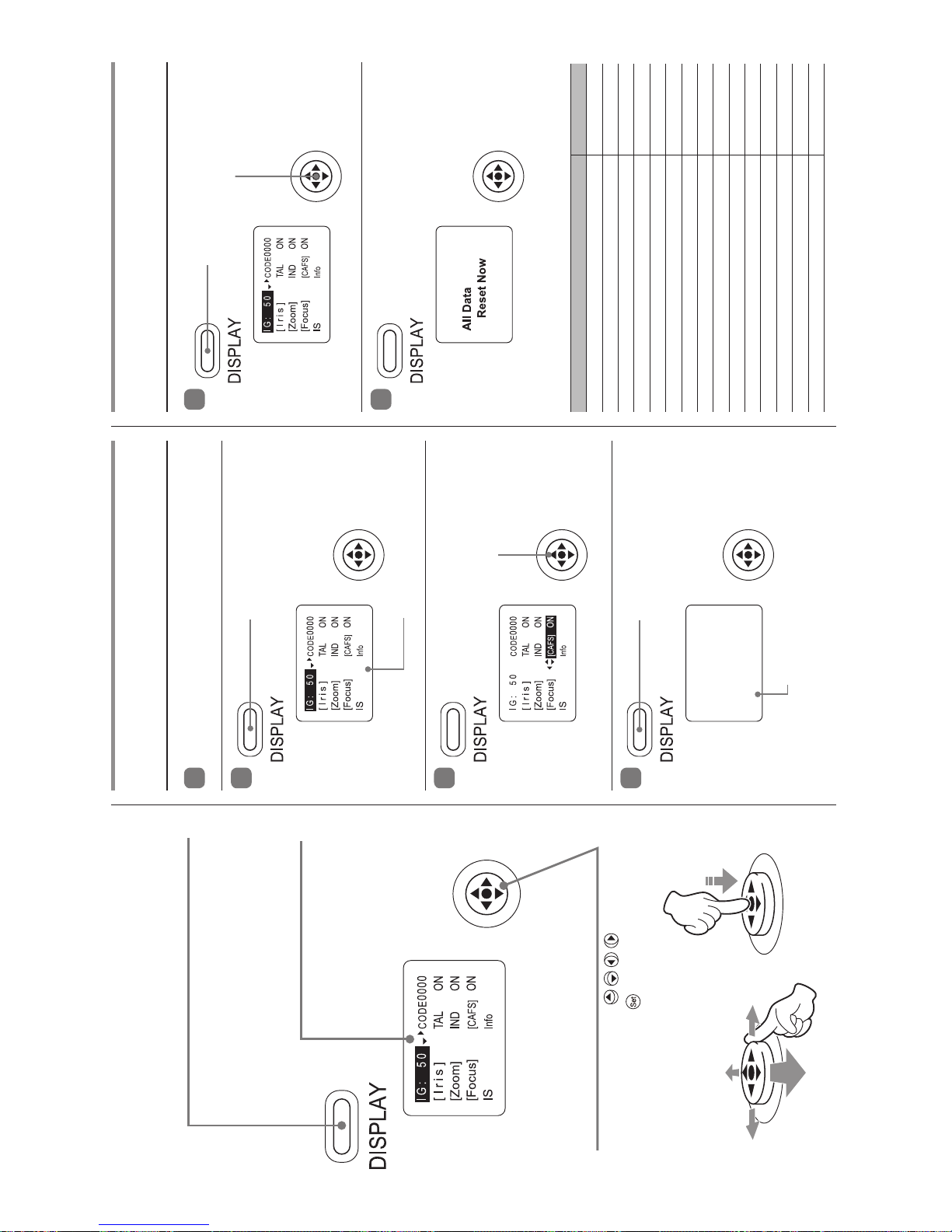
1
基本操作
1
レンズの電源を入れます。
2
3
4
リセット操作
1
2
下記表のデータがリセットされ、デフォルト値に戻ります。
DISPLAY スイッチを押します。
DISPLAY スイッチとカーソルボタン
を同時に 2 秒以上押し続けます。
DISPLAY スイッチを押します。
カー ソル ボタ ンを 使用し、
各種設定を行います。
ディスプレイが点灯します。
ディスプレイが消灯し、変更内容が保存され
ます。
項目 デフォルト値
CAFS の設定 ON
タリー点灯設定 ON
インジケーターの点灯設定 ON
アイリス補正の ON / OFF 切替え ON
アイリスクローズ検出の ON / OFF 切替え 出荷時設定値
ズームサーボの立上がり特性の設定 50
ズームサーボの止まり際特性の設定 50
ズームメカ端部止まり際特性の設定 91
各プリセットのズーム立上がり特性の設定 99
各プリセットのズーム止まり際特性の設定 91
アナログデマンドカーブ特性の設定 5
*
ズームデマンドからのサーボモード設定 Sped
CAM モード設定 0
フォーカスデマンドのカーブ特性 STD
タリー光量の設定 出荷時設定値
* XJ60x のみ "3"。
DISPLAY
スイッチ
ディスプレイの表示を ON / OFF します。
ディスプレイ
操作しない状態 が 2 分以上
続くと表示が消えます。
カーソルボタン
カーソルを上下左右( )へ倒して動
かします。中央部分(
)を押して確定します。
Page 40
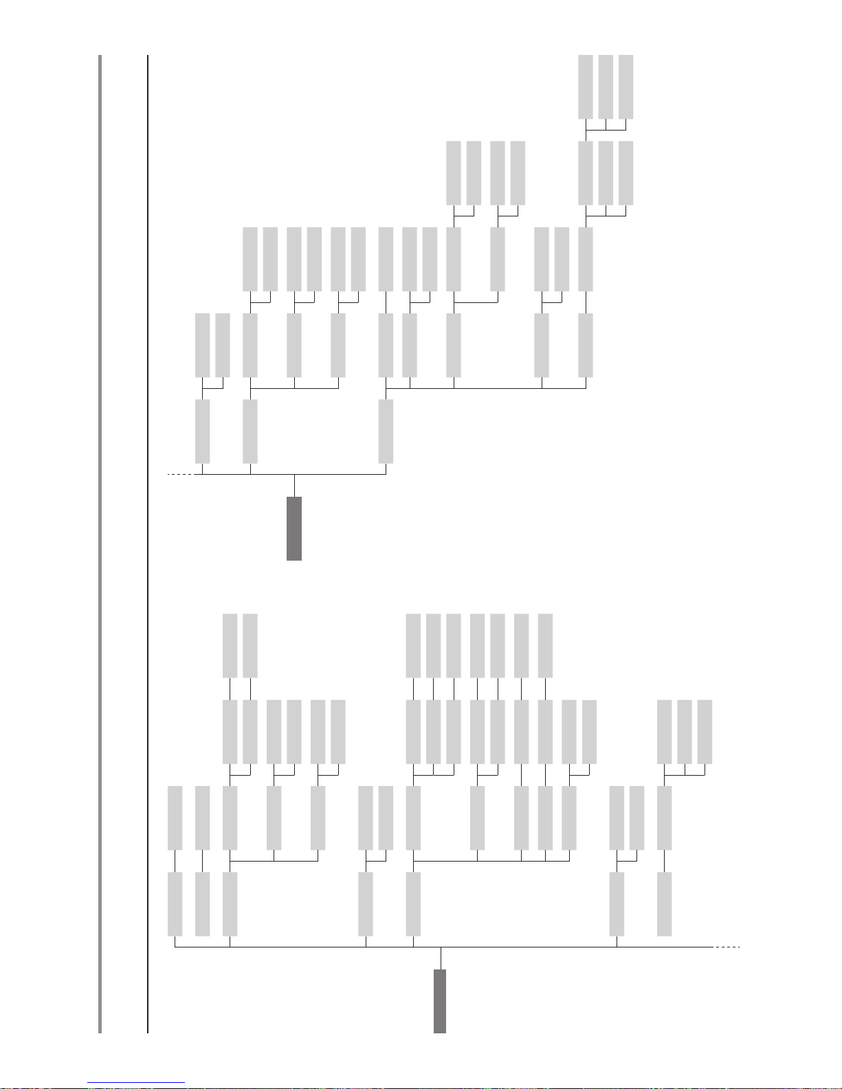
2
IG 01 - 99
CODE 0000 - 1111
[Iris] I-Gain Auto 01 - 99
Remote 01 - 99
Comp ON
OFF
Close ON
OFF
TAL ON
OFF
[Zoom] Movement Start 00 - 99
Stop 00 - 99
TOP
End 00 - 99
PreMovement
Start 00 - 99
Stop 00 - 99
CurveMode Demand 1 - 9
CamMode CamMode 0 - 5
Control Sped
Posi
IND ON
OFF
[Focus] Curve STD
FAR
Near
[CAFS] ON
OFF
IS MechLock ON
OFF
TOP
SwSetting Alt
Mon
OffState OFF
Std
Info Tally 01-99
Encoder ON
OFF
Initialize Zoom ON
OFF
Focus ON
OFF
CamSeri ON
OFF
Adjust Camera Fol Iris
-32760 ‒ 32760
Zoom
-32760 ‒ 32760
Focus
-32760 ‒ 32760
ディスプレイメニュー階層
Page 41
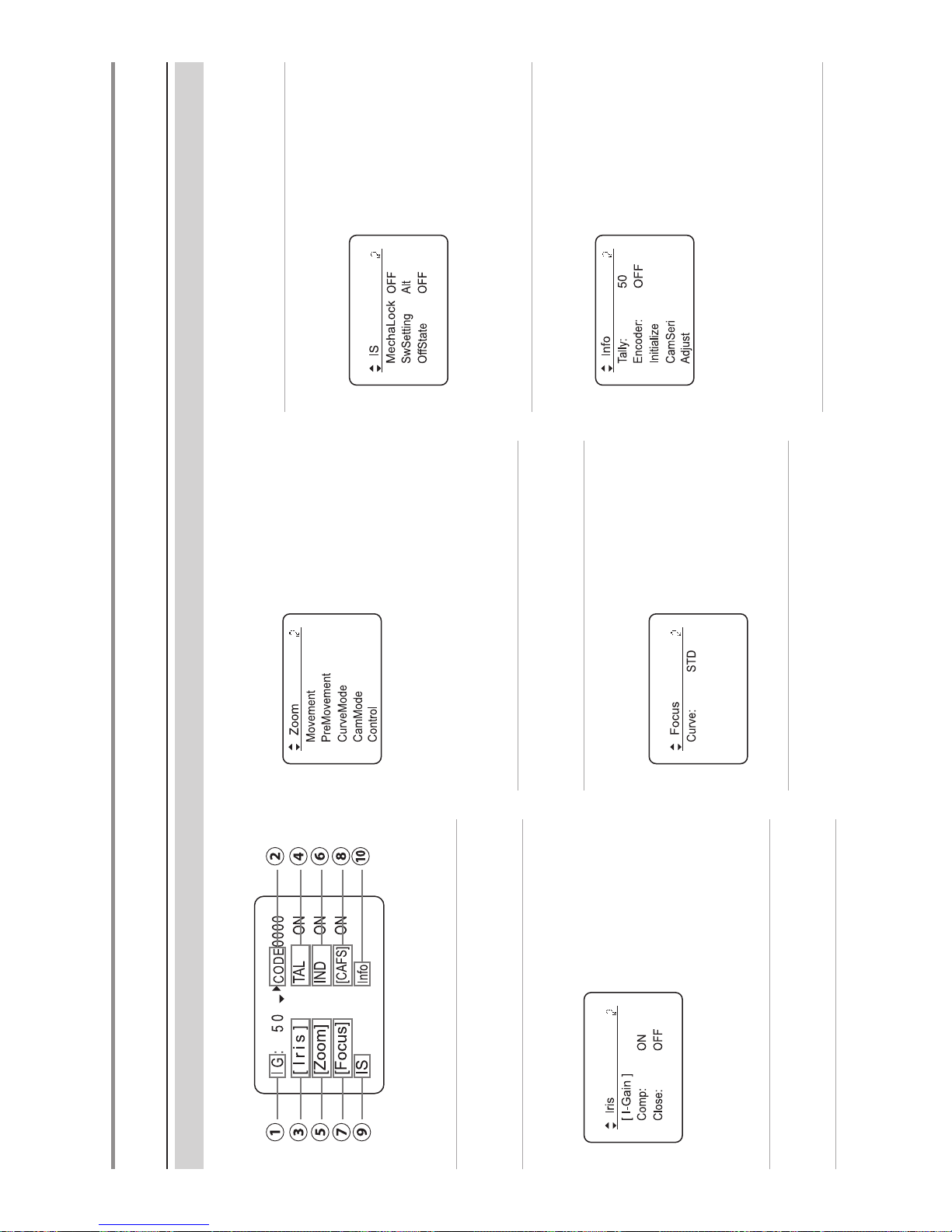
3
TOP
画面及び各種画面
DISPLAY スイッチを押したときに最初に表示される画面が TOP 画面です。各種設定や設定状況の確認を行うことができます。
①
IG
オートアイリスゲインの調整
②
CODE
レンズコードの設定
③
[Iris]
アイリス制御に関する設定
[I-Gain]
:
アイリスゲインの設定(オート/リモート)
Comp
:
アイリス補正の ON / OFF
Close
:
クローズ検出の ON / OFF
④
TAL
タリーの点灯/消灯設定
TOP
画面
⑤
[Zoom]
ズーム制御に関する設定
Movement
:
サーボの立上がり/止まり際、メカ端
部止まり際特性
PreMovement
:
各プリセットのズーム立上がり特性
CurveMode
:
アナログデマンドカーブ特性
CamMode
:
CAM モードの設定
Control
:
デマンドからのサーボモード設定
⑥
IND
インジケーターの点灯/消灯設定
⑦
[Focus]
フォーカス制御に関する設定
Curve
:
デマンドのカーブ特性
⑧
[CAFS]
CAFS 機能の ON / OFF 設定
⑨
IS
IS 機能に関する設定
MechaLock
:
メカロック設定
SwSetting
:
操作スイッチ設定
OffState
:
モード設定
⑩
Info
その他各種設定
Tally
:
タリー光量の設定
Encoder
:
エンコーダー出力設定
Initialize
:
初期化動作設定
CamSeri
:
カメラシリアル通信の有効/無効
Adjust
:
カメラフォロー電圧調整
Page 42
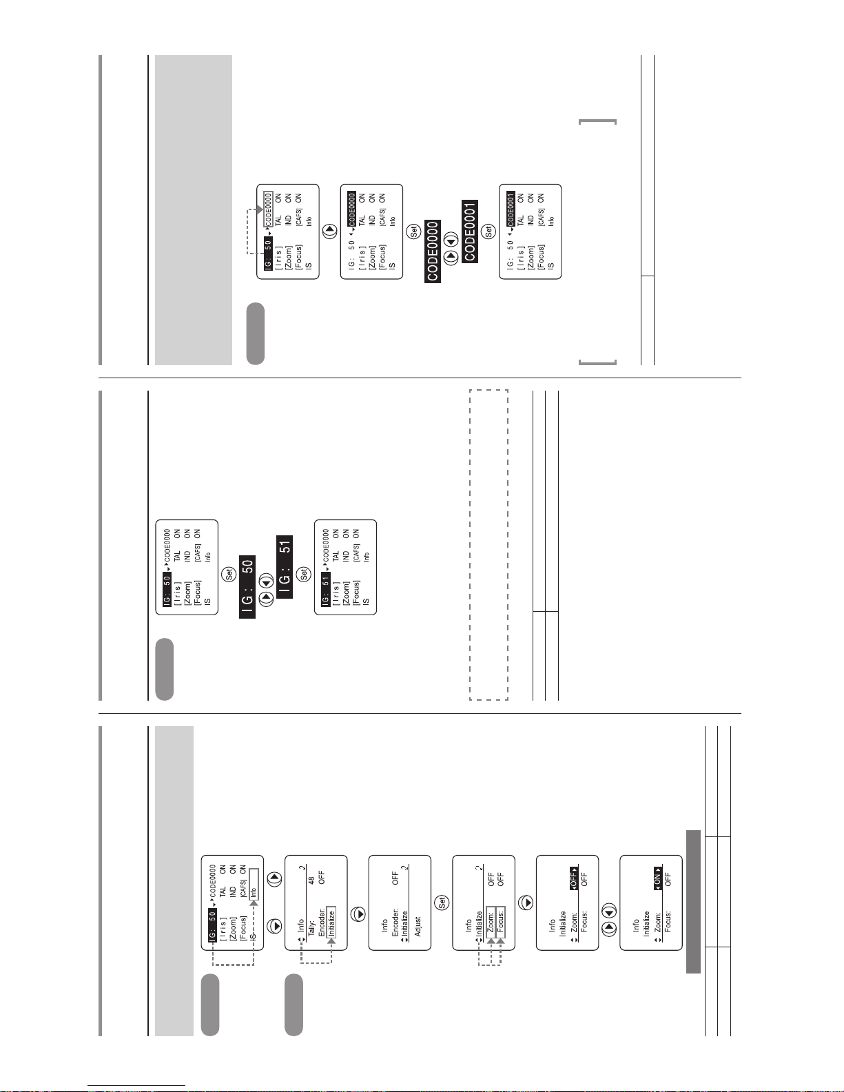
4
操作例(初期化動作設定)
ズームとフォーカスの初期化動作を電源投入時に行うか行わな
いかを設定します。
Top
画面
×
4
、
Info
画面
×
3
(ズームの場合)
で選択
電源を入れ直してください
選択項目
(D)
OFF ON
機能 初期化動作なし 初期化動作あり
(D):デフォルト値
IG
オートアイリスゲインの設定
Top
画面
※ 1
(点滅)
で調整
※ 2
(51 にする場合)
※ 3
※(注 1): アイ リスの動作を 確認しながら ゲイン調整を行う際は、カ メラのアイリ ス
モードを[AUTO]にします。
※(注 2): ハンチングがおこらない範囲でゲインが最高になるよう設定してください。
※(注 3): アイリ スゲインの設定値は、1 ページに記載し てあります「リセット 操作」
を行ってもリセットされません。
トリ マーによる設定につ いて は、取 扱説 明書 10 ペ ージ
"
2-4
アイリスゲイン調整
"
をご参照ください。
選択項目 01 〜 99
機能 ゲイン最小 ゲイン最大
デフォルト値:50
CODE
レンズコードの設定
レンズに番号を付け、カメラ側に送り返す事ができます。0000
から 1111 の 2 進数で 16 通りから選択できます。
カメラ機能によりますが、カメラ側でレンズの識別に使用する
場合があります。
カメラメーカーからの指示があった場合に設定します。
Top
画面
(点滅)
で調整
(0001 にする場合)
※(注)
• 数値は 2 進数で 16 通り変化します。
• レンズコードはリセット操作を行っても、数値は変わりません。
選択項目 0000 〜 1111
デフォルト値:工場出荷時に設定されます。
Page 43
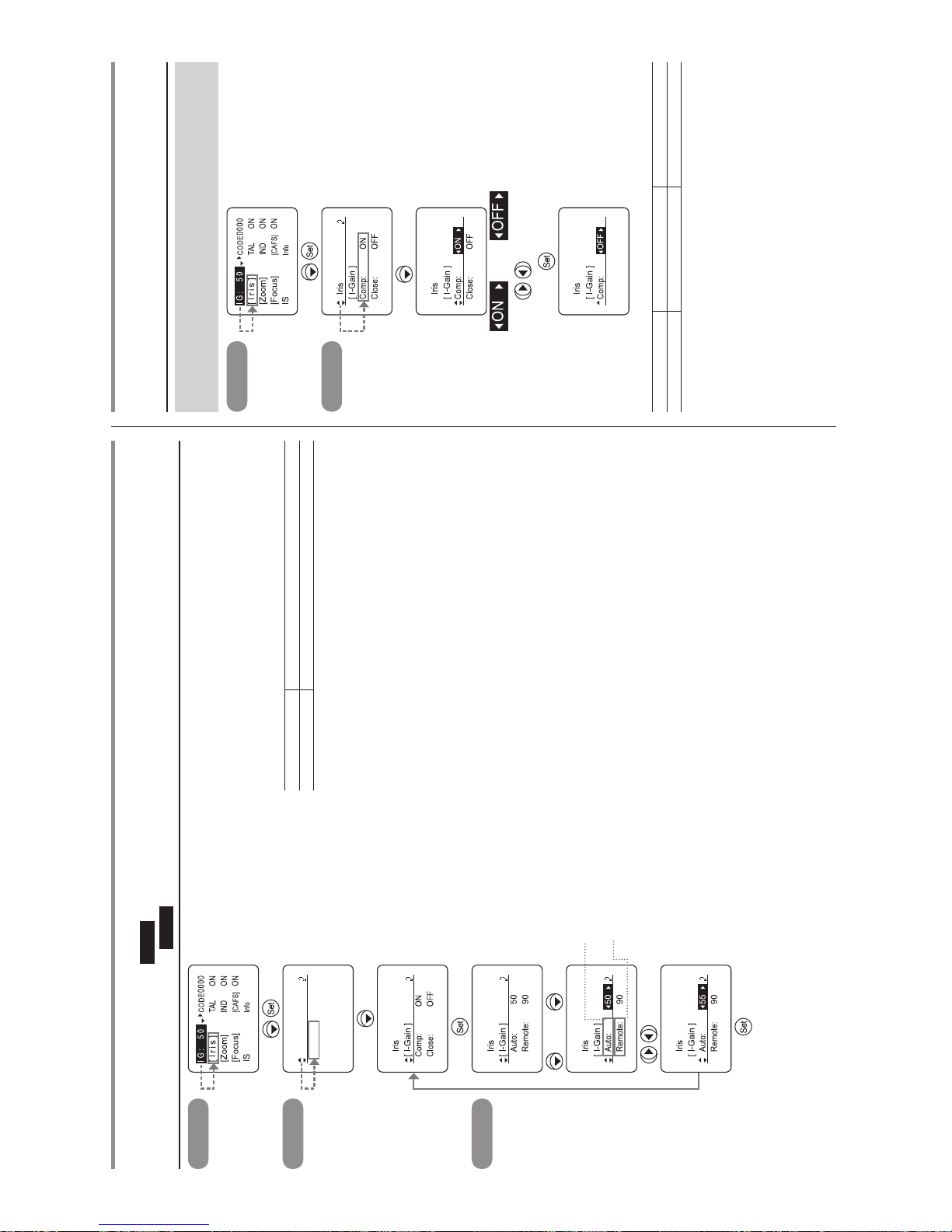
5
※(注 1): ア イリス の動作を確認しながら ゲイン 調整を 行う際 は、カメ ラのア イリ
スモ ード を[AUTO](オー トア イリ スゲイ ンを 設定 する 場合)、 また は
[REMOTE](リモートアイリスゲインを設定する場合)にします。
※(注 2): ハンチングがおこらない範囲でゲインが最高になるよう設定してください。
※(注 3): アイリスゲインの設定値は、1 ページに記載してあります。「リセット操作」
を行ってもリセットされません。
選択項目 01 〜 99
機能 ゲイン最小 ゲイン最大
オートアイリスゲインデフォルト値:50
リモートアイリスゲインデフォルト値:90
Top
画面
Iris
画面
Iris
[ I-Gain ]
Comp: ON
Close: OFF
※ 1
I-Gain
画面
または
×
2
オートアイリスゲインを
設定する場合
リモートアイリスゲイン
を設定する場合
で調整
※ 2
(55 にする場合)
※ 3
[Iris] – [I-Gain]
オートアイリスゲインの設定
Auto
リモートアイリスゲインの設定
Remote
[Iris] – Comp
アイリス補正
ON
/
OFF
エクステンダー使用時にアイリスを 2F 相当のオープン側に補
正する機能の ON / OFF 設定です。
Top
画面
Iris
画面
×
2
または
で選択
(OFF に設定する場合)
選択項目
(D)
ON OFF
機能 アイリス補正する アイリス補正しない
(D):デフォルト値
Page 44
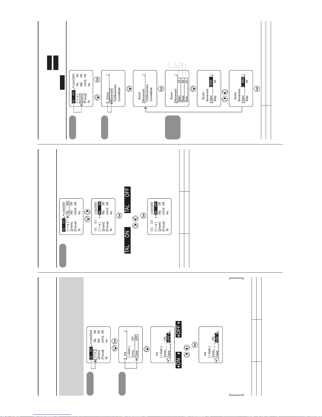
6
[Iris] – Close
アイリスクローズ検出
ON
/
OFF
アイリス補正機能が ON になっているときに、エクステンダー
(2.0x)を入れるとアイリスをクローズにできない状態になりま
す。その対策としてクローズを検出したときは、クローズさせ
る機能を設定できます。
Top
画面
Iris
画面
×
3
または
で選択
(ON に設定する場合)
* Comp(アイリス補正)が ON 設
定時に アイリス クローズ検 出が
有効になり、表示されます。
※(注): カメラにより、レンズのアイリス補正とカメラからのアイリスコントロー
ルとの相互関係でアイリスが正常に動作できない場合があります。そのと
きはアイリスクローズ検出機能を OFF にしてください。
選択項目 ON OFF
機能
アイリスクローズ検出する
クローズ検出しない
デフォルト値:工場出荷時にカメラのインターフェースによって設定されます。
TAL
タリー点灯/消灯
Top
画面
または
(点滅)
で選択
(OFF に設定する場合)
選択項目
(D)
ON OFF
機能 点灯 消灯
(D):デフォルト値
[Zoom] – Movement
ズームサーボの立上がり特性
Start
ズームサーボの止まり際特性
Stop
メカ端部止まり特性
End
Top
画面
×
2
、
Zoom
画面
Movement
画面
立上がりを設定する場合
止まり際を設定する場合
メカ端部止まり際を設定
する場合
(立上がりを設定する場合)
で調整
(48 にする場合)
選択項目 00 〜 99
機能 ゆっくり立ち上がる 急に立ち上がる
サーボの立上がり特性 デフォルト値:50
サーボの止まり際 デフォルト値:50
メカ端部止まり際 デフォルト値:91
Page 45
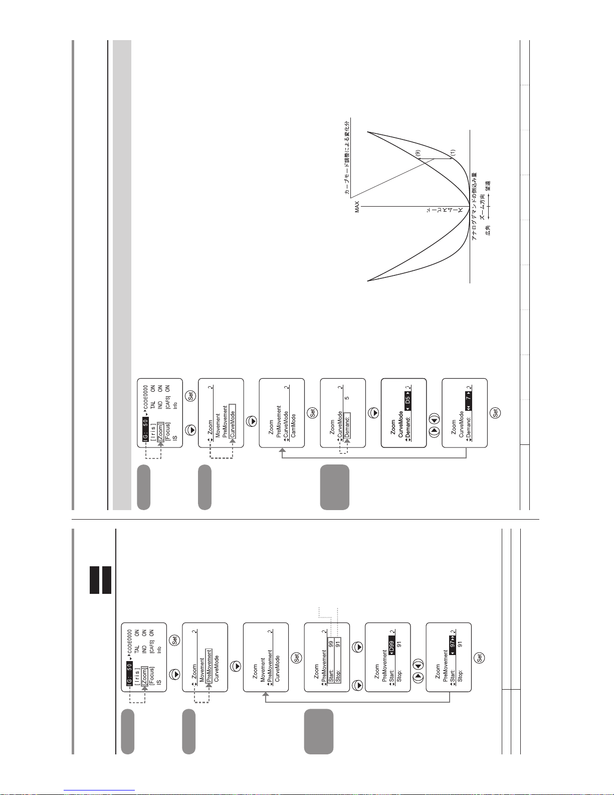
7
[Zoom] – PreMovement
各プリセットのズーム立上がり特性
Start
各プリセットのズーム止まり際特性
Stop
Top
画面
×
2
、
Zoom
画面
×
2
PreMovement
画面
立上がり特性を設定する
場合
止まり際特性を設定する
場合
または
×
2
で調整
(97 にする場合)
選択項目 00 〜 99
機能 ゆっくり立ち上がる 急に立ち上がる
立上がり特性デフォルト値:99
止まり際特性デフォルト値:91
Top
画面
×
2
、
Zoom
画面
×
3
CurveMode
画面
で調整
(7 にする場合)
[Zoom] – CurveMode
アナログデマンドカーブ特性
アナログズームデマンドの倒し込み量に対するズームスピードの特性を可変させることができます。
選択項目 1 2 3 4
(D)
5 6 7 8 9
(D):デフォルト値
Page 46
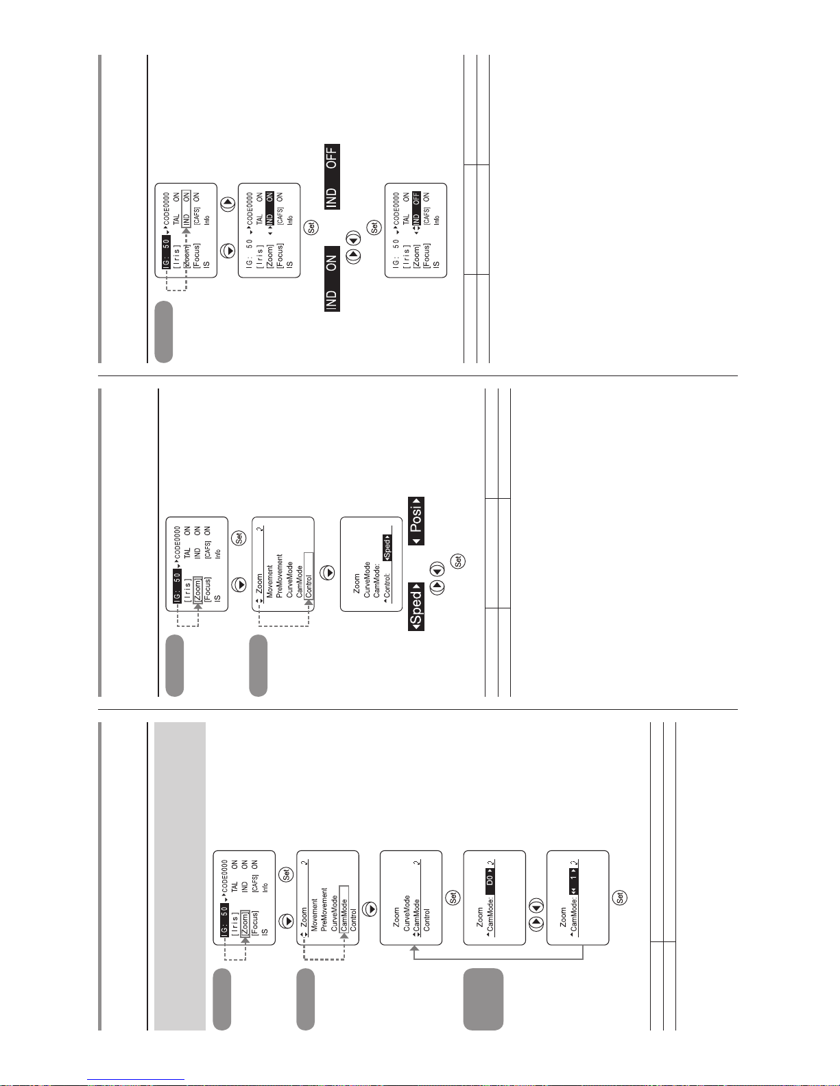
8
[Zoom] – CamMode – Demand
CAM
モード設定
ズームコントロールに対して、ズームの画角変化を補正するこ
とができます。
0 は補正なし、5 は最大に補正します。
Top
画面
×
2
、
Zoom
画面
×
4
CamMode
画面
で調整
(1 にする場合)
選択項目
(D)
0 〜 5
機能 補正なし 補正最大
(D):デフォルト値
[Zoom] – Control
ズームデマンドからのサーボモード設定
(仕様によっては状態表示の確認のみ)
Top
画面
×
2
、
Zoom
画面
×
5
または
で選択
表示項目
(D)
Sped Posi
機能 スピードサーボ ポジションサーボ
(D):デフォルト値
IND
インジケーターの点灯/消灯
Top
画面
×
2
、
または
(点滅)
で選択
(OFF に設定する場合)
選択項目
(D)
ON OFF
機能 点灯 消灯
(D):デフォルト値
Page 47
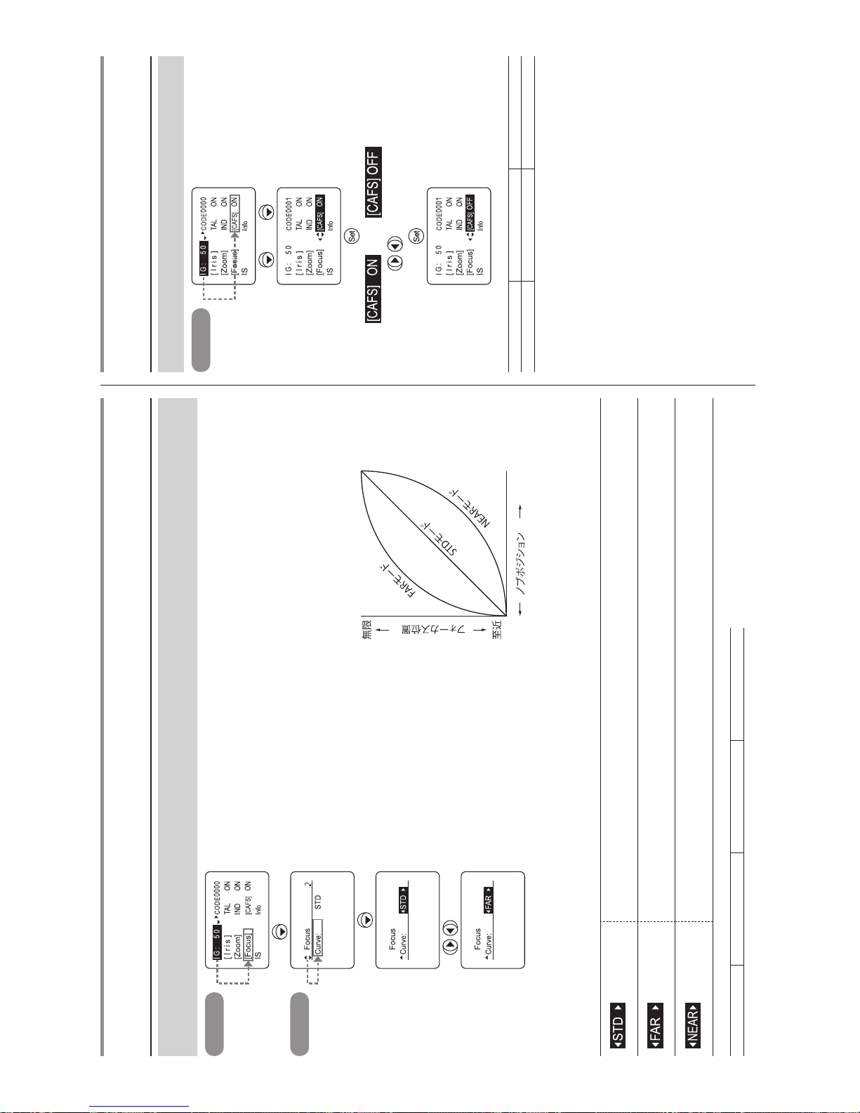
9
Top
画面
×
3
Focus
画面
で選択
(FAR モードに設定する場合)
[Focus] – Curve
フォーカスデマンドのカーブ特性
カメラ経由でフォーカスコントロールを行う場合、通常はフォーカス操作のカーブ特性を設定することができます。
( ただし、シリアルデータ制御の場合を除く。)
選択項目
(D)
STD FAR NEAR
(D):デフォルト値
(標準モード) 操作ノブの回転量に対するフォーカスレンズグループの移動量の関係が、ほぼリニアな標準的な特性モード
(Far モード)
遠距離の被写体の焦点合わせがやり易くなるように、無限遠でのカーブの特性を緩やかにして、遠距離の分
解能を上げたモード
(Near モード)
Far モードとは反対に、至近側での焦点合わせがやり易くなるように、至近側でのカーブ特性を緩やかにし
て、近距離での分解能を上げたモード
CAFS
CAFS
の設定
フォーカシングによる画角変化をゼロレベルに抑えます。
Top
画面
×
3
、
または
(点滅)
で選択
(OFF に設定する場合)
選択項目
(D)
ON OFF
機能 有効 無効
(D):デフォルト値
Page 48
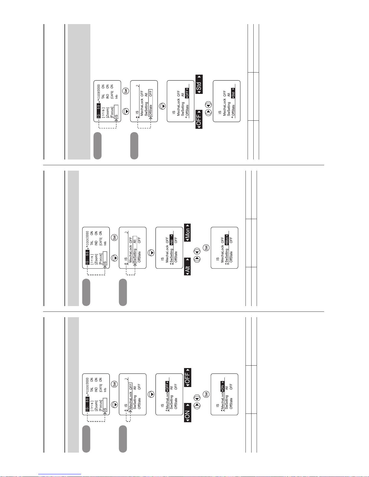
10
IS – MechaLock
IS
メカロック設定
撮影中の IS を強制的にロックします。
Top
画面
×
4
、
IS
画面
または
で選択
(ON に設定する場合)
選択項目
(D)
OFF ON
機能 IS メカロック無効 IS メカロック有効
(D):デフォルト値
IS – SWSetting
IS
操作スイッチ設定
IS 操作スイッチの状態(Alt / Mon)を選択します。
Top
画面
×
4
、
IS
画面
×
2
または
で選択
選択項目
(D)
Alt Mon
機能 オルタネイト動作 モーメンタリー動作
(D):デフォルト値
IS – OffState
IS
モード設定
IS スイッ チを OFF にしたときの IS 操作(Off / IS 標準特性)
を選択します。
(本編 p.17 参照)
Top
画面
×
4
、
IS
画面
×
3
または
Std
で選択
(Std に設定する場合)
選択項目
(D)
OFF Std
機能 IS 操作無効 IS 操作標準特性
(D):デフォルト値
Page 49
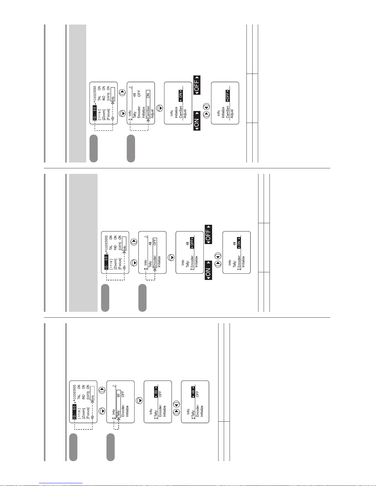
11
Info – Tally
タリー光量の設定
Top
画面
×
4
、
Info
画面
で調整
(48 にする場合)
選択項目 01 〜 99
機能 光量最小 光量最大
デフォルト値:工場出荷時にデフォルトして設定されます。
Info – Encoder
エンコーダー出力設定
Zoom および Focus エンコーダー出力機能の有効/無効を設定
します。有効の場合はバーチャルコネクターより出力されます。
詳しくは販売代理店またはキヤノン(株)にお問い合わせくだ
さい。
Top
画面
×
4
、
Info
画面
×
2
または
で選択
(ON に設定する場合)
選択項目
(D)
OFF ON
機能 出力無効 出力有効
(D):デフォルト値
Info – CamSeri
カメラシリアル通信の有効/無効
カメラとレンズ間のインターフェースの自動認識の有効/無効
(アナログ制御)を切替えます。
Top
画面
×
4
、
Info
画面
×
4
または
で選択
選択項目
(D)
ON OFF
機能 有効 無効
(D):デフォルト値
Page 50
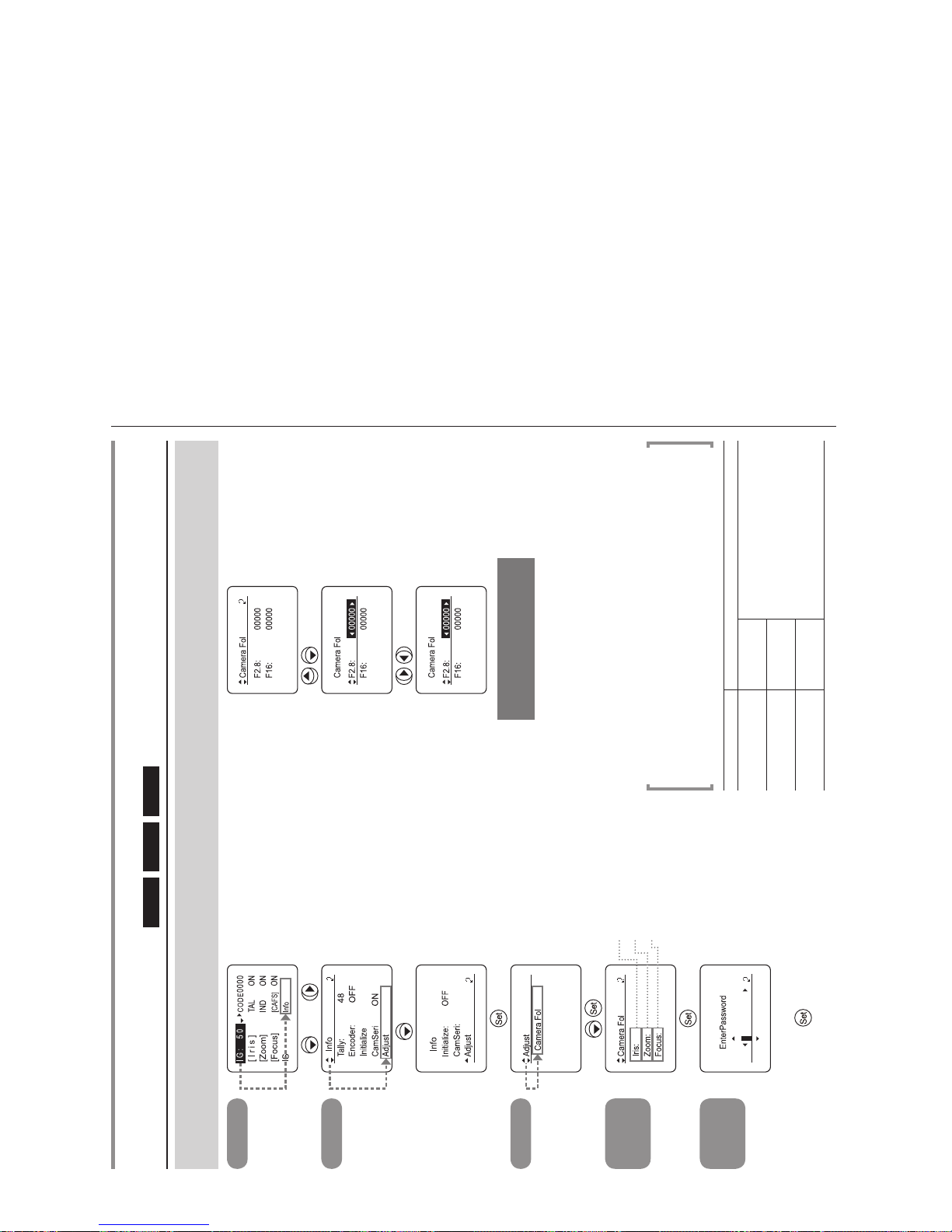
12
Top
画面
×
4
、
Info
画面
×
5
Adjust
画面
Camera Fol
画面
アイリスの設定をする場合
ズームの設定をする場合
フォーカスの設定をする
場合
EnterPassword
画面
パスワード入力
Info – Adjust – Camera Fol
カメラフォロー電圧調整
Iris
Zoom
Focus
カメラ側(インジケーターなど)の都合によりレンズ側の変更が必要なとき、カメラに送り返す電圧を変更できます。
パスワードが必要ですので、販売代理店またはキヤノン(株)にお問い合わせください。
で選択
※ 1
で調整
※ 2
DISPLAY
キーを押すと、
データが保存されます
※(注 1): 選択された項目のデータが表示されます。
初めてこの操作をした場合は工場出荷時の値が表示されます。個々のレンズ
に調整された値ですので、元に戻すことも考慮し、メモをしておいてくださ
い。
※(注 2): 数値は、相対値表示です。
-32760 から 32760 まで選択できますが、元の値より大幅な変更は、他の機
器に影響を及ぼす可能性がありますので、ご注意ください。
※(注)
• リセット操作を行っても、工場出荷時の設定に戻りません。
• パスワードは電源 OFF 時に無効になります。
• パスワード文字入力は上下ボタンで文字を探し、桁の移動および修正をするときは
左右ボタンで行ってください。
選択項目 選択範囲
Iris
F2.8
-32760 〜 ( 0 ) 〜 32760
F16
Zoom
Wide
Tele
Focus
Near
Far
参考:( )内の数値は、工場出荷時の参考値です。
Page 51
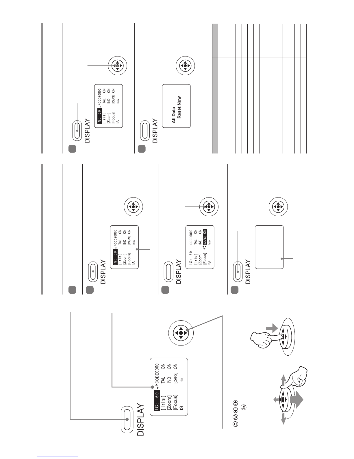
E1
Basic operation
1
Turn the lens power on.
2
3
4
Reset operation
1
2
The data in the table below are reset and return to the default
values.
Press the DISPLAY switch.
Holding down the DISPLAY switch and
cursor button together for two seconds.
Press the DISPLAY switch.
Use the cursor button to
select and set functions.
The display turns on.
The display turns off, and changes made to
the settings are stored.
Setting item Default value
CAFS setting ON
Tally lamp lighted settings ON
Indicator lighted settings ON
Setting the iris correction to ON/OFF ON
Setting the iris close detection to ON/OFF
Factory setting value
Setting the zoom servo start characteristics 50
Setting the zoom servo stop characteristics 50
Setting the zoom mechanism end stop characteristics
91
Setting the zoom start characteristics for preset operations99Setting the zoom stop characteristics for preset operations
91
Setting the analog demand curve characteristics 5*
Setting the servo mode type from the zoom demand
Sped
CAM mode settings 0
Focus demand curve characteristics STD
Tally lamp light quantity setting
Factory setting value
* “3” only for the XJ60x.
DISPLAY switch
Turn the display ON/OFF.
Display
It turns off if left for 2 minutes
without operation.
Cursor button
Press the cursor button up/down/left/right
(
) to move the cursor. Press the
center (
) to conrm.
Page 52
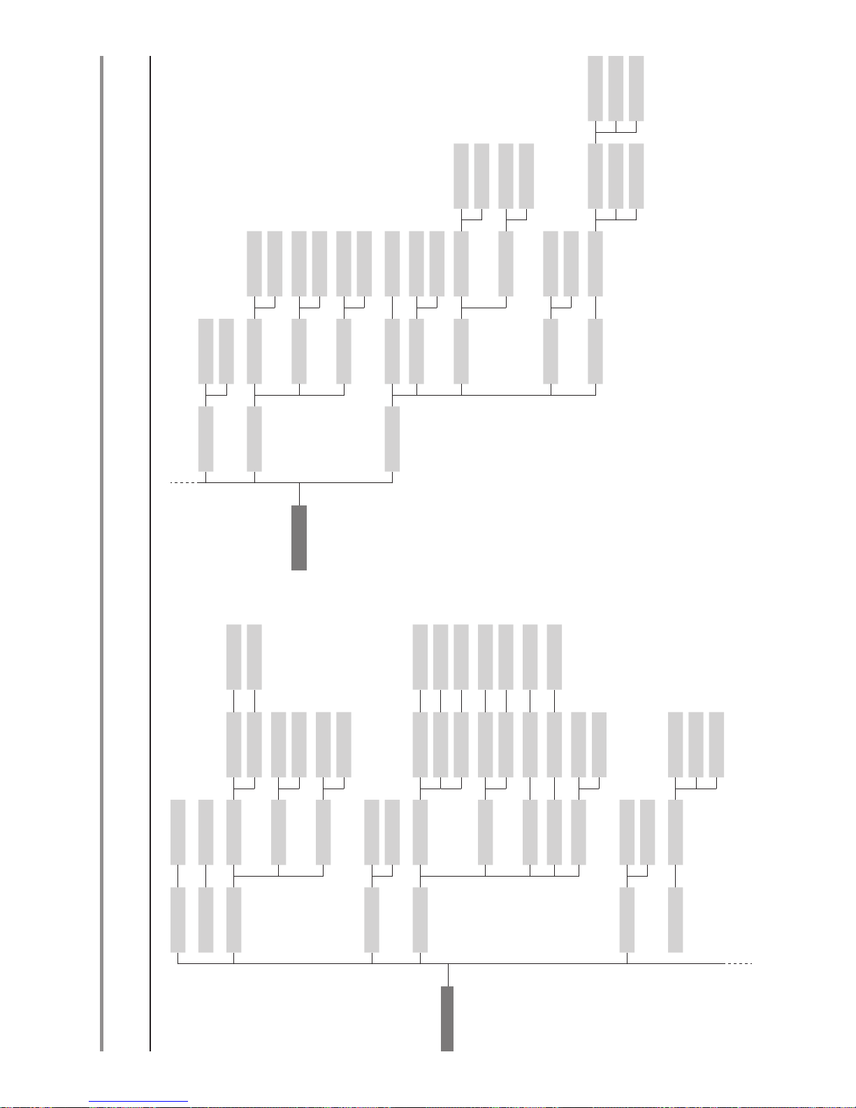
E2
IG 01 - 99
CODE 0000 - 1111
[Iris] I-Gain Auto 01 - 99
Remote 01 - 99
Comp ON
OFF
Close ON
OFF
TAL ON
OFF
[Zoom] Movement Start 00 - 99
Stop 00 - 99
TOP
End 00 - 99
PreMovement
Start 00 - 99
Stop 00 - 99
CurveMode Demand 1 - 9
CamMode CamMode 0 - 5
Control Sped
Posi
IND ON
OFF
[Focus] Curve STD
FAR
Near
[CAFS] ON
OFF
IS MechLock ON
OFF
TOP
SwSetting Alt
Mon
OffState OFF
Std
Info Tally 01-99
Encoder ON
OFF
Initialize Zoom ON
OFF
Focus ON
OFF
CamSeri ON
OFF
Adjust Camera Fol Iris
-32760 – 32760
Zoom
-32760 – 32760
Focus
-32760 – 32760
Display menu hierarchy
Page 53
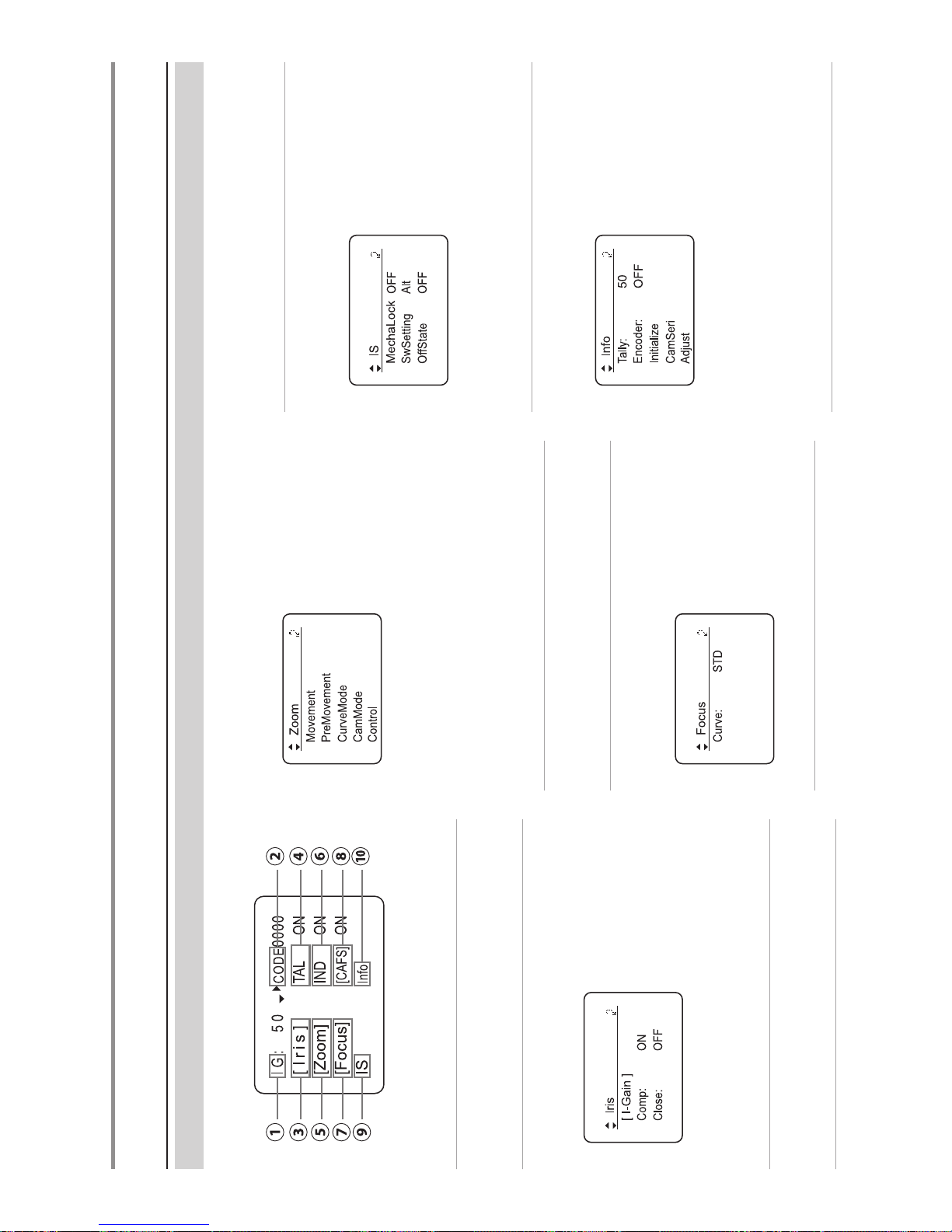
E3
TOP screen and various screens
The TOP screen is an initial screen displayed when the DISPLAY switch is pressed. Digital functions can be set and viewed from this screen.
①
IG
Adjusting the auto iris gain
②
CODE
Lens code setting
③
[Iris]
Settings related to iris control
[I-Gain]:
Setting the iris gain (Auto/Remote)
Comp:
Setting the iris correction to ON/OFF
Close:
Setting the iris close detection to ON/OFF
④
TAL
Setting the tally lamp ON/OFF
TOP screen
⑤
[Zoom]
Settings related to zoom control
Movement:
Servo start/stop characteristics,
mechanism end stop characteristics
PreMovement:
Setting the zoom start characteristics
for preset operations
CurveMode:
Setting the analog demand curve
characteristics
CamMode:
CAM mode settings
Control:
Setting the servo mode type from the
zoom demand
⑥
IND
Setting the indicator ON/OFF
⑦
[Focus]
Settings related to focus control
Curve:
Focus demand curve characteristics
⑧
[CAFS]
Setting the CAFS ON/OFF
⑨
IS
Settings related to IS function
MechaLock:
IS mechanical lock setting
SwSetting:
IS operation switch setting
OffState:
IS mode setting
⑩
Info
Other settings
Tally:
Tally lamp light quantity setting
Encoder:
Encoder output setting
Initialize:
Initialize operation setting
CamSeri:
Setting the camera serial communication to
ON/OFF
Adjust:
Adjusting the Camera Fol Voltage
Page 54
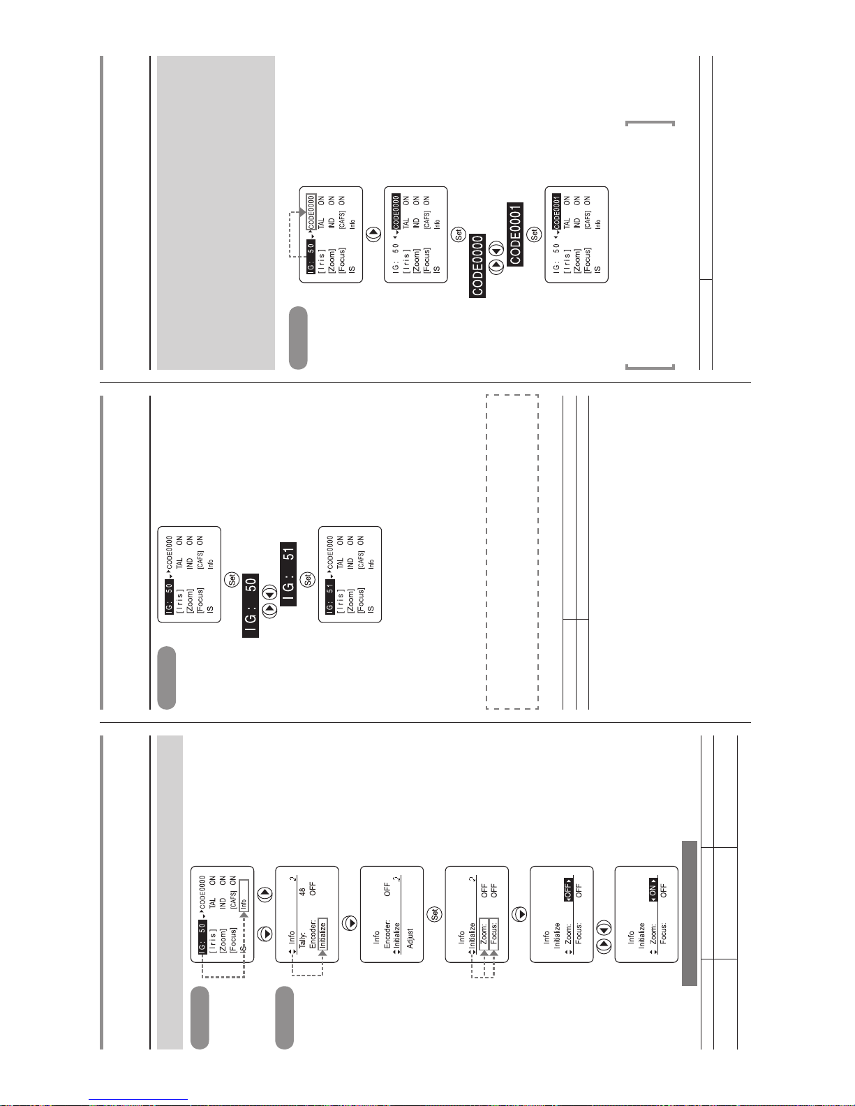
E4
Operation example (initialize operation setting)
Set whether or not to execute the zoom and focus initialization upon power on.
Top screen
× 4,
Info screen
× 3
(to set zoom)
to select
Turn the power off then on.
Selection item
(D)
OFF ON
Function
Initialization operation not
performed
Initialization operation
performed
(D): Default value
IG
Setting the auto iris gain
Top screen
*
1
(ashing)
to adjust*
2
(to set to “51”)
*
3
*(Note 1): When adjusting the gain while checking the iris op eration, set the camera’s
iris mode to [AUTO].
*(Note 2): Set in such a way that the maximum gain is obtained within the range where
hunting will not occur.
*(Note 3): The iris gain setting is not reset even when the steps descr ibed in “Reset
operation” on page E1 are taken.
For information on setting the auto iris gain using a trimmer,
refer to “2-4 Iris Gain Adjustment” on page E8 in the Operation
Manual.
Selection item 01 – 99
Function Minimum gain Maximum gain
Default value: 50
CODE
Lens code setting
Give a number (code) to the lens, and the given number (code)
can be sent to the camera side. Any of 16 different codes from
0000 to 1111 in binary format can be selected.
Although it depends on the camera’s functions, these codes
are sometimes used to differentiate between the lenses at the
camera side.
Set these co des w hen inst ructed t o do so by the camera
manufacturer.
Top screen
(ashing)
to adjust
(to set to “0001”)
*(Note)
• The code has a binary format, and it comes in 16 variations.
• Th e le ns code remai ns uncha nged even after th e r esett ing
operation has been performed.
Selection item 0000 – 1111
Default value: This is set at the factory prior to shipment.
Page 55
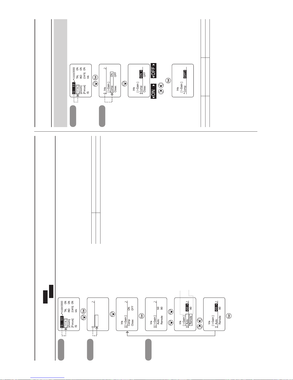
E5
*(Note 1): When adjusting the gain while checking the iris op eration, set the camera’s
iris mode to [AUTO] (to set the auto iris gain) or [REMOTE] (to set the remote
iris gain).
*(Note 2): Set in such a way that the maximum gain is obtained within the range where
hunting will not occur.
*(Note 3): The iris gain setting is not reset even when the steps descr ibed in “Reset
operation” on page E1 are taken.
Selection item 01 – 99
Function Minimum gain Maximum gain
Auto iris gain default value: 50
Remote iris gain default value: 90
Top screen
Iris screen
Iris
[ I-Gain ]
Comp: ON
Close: OFF
*
1
I-Gain screen
or × 2
to set the auto iris gain
to set the remote iris gain
to adjust*
2
(to set to “55”)
*
3
[Iris] – [I-Gain]
Setting the auto iris gain
Auto
Setting the remote iris gain
Remote
[Iris] – Comp
Setting the iris correction to ON/OFF
Set the function that corrects the iris by opening it by an amount
equivalent to 2F when using an extender to ON or OFF.
Top screen
Iris screen
× 2
or
to select
(to set to OFF)
Selection item
(D)
ON OFF
Function Iris correction No iris correction
(D): Default value
Page 56
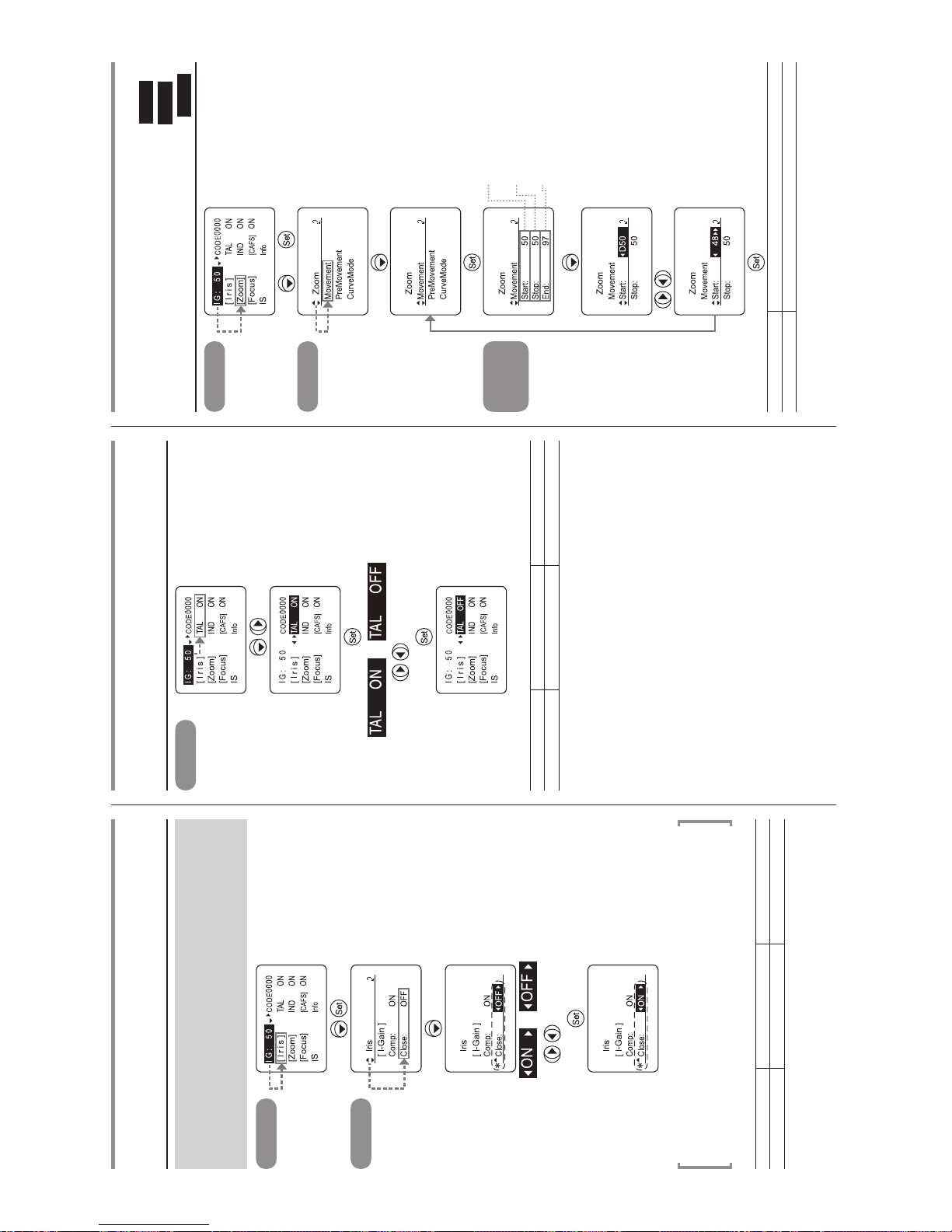
E6
[Iris] – Close
Setting the iris close detection to ON/OFF
This iris cannot be closed when the extender (2.0x) is inserted
while the iris correction function is set to ON. To compensate for
this, a function which closes the iris when iris close has been
detected can be set.
Top screen
Iris screen
× 3
or
to select
(to set to ON)
* Th is ap pea rs an d iri s clo se
detection takes effect whe n ON
is selected as the Comp setting
(iris correction).
*(Note): Dependi ng on the camera, it may not be possible f or the iris to operate
properly due to the interaction between the iris correctio n function of the
lens and the iris control exercised from the camera. At such a time, set the
iris close detection to OFF.
Selection item ON OFF
Function
Iris close detection
No iris close detection
Default value: This is set according to the camera interface at the factory prior to shipment.
TAL
Setting the tally lamp ON/OFF
Top screen
or (ashing)
to select
(to set to OFF)
Selection item
(D)
ON OFF
Function Lighted Extinguished
(D): Default value
[Zoom] – Movement
Setting the zoom servo start characteristics
Start
Setting the zoom servo stop characteristics
Stop
Setting the zoom mechanism end stop characteristics
End
Top screen
× 2,
Zoom screen
Movement
screen
to set the servo start
characteristics
to set the servo stop
characteristics
to set the mechanism end
stop characteristics
(to set the servo start
characteristics)
to adjust
(to set to “48”)
Selection item 00 – 99
Function Slow start Quick start
Servo start characteristics default value: 50
Servo stop characteristics default value: 50
Mechanism end stop characteristics default value: 91
Page 57
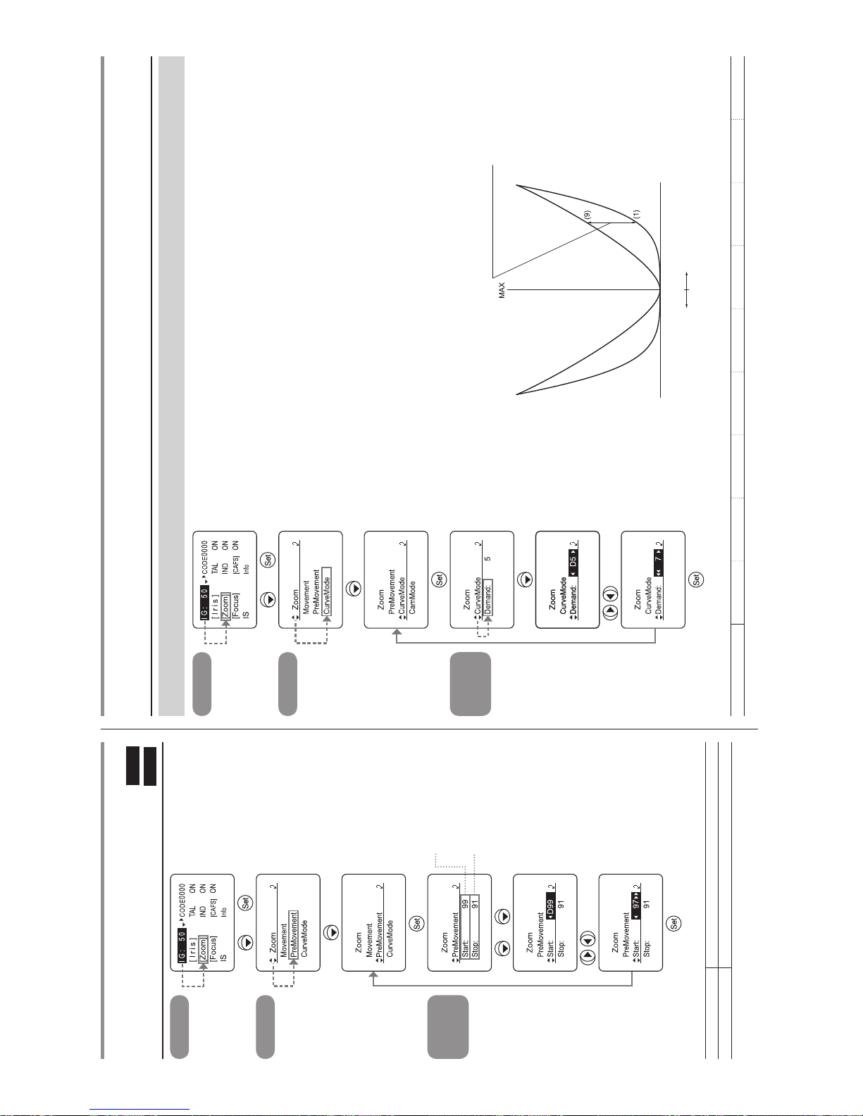
E7
[Zoom] – PreMovement
Setting the zoom start characteristics for preset operations
Start
Setting the zoom stop characteristics for preset operations
Stop
Top screen
× 2,
Zoom screen
× 2
PreMovement
screen
to set the start
characteristics
to set the stop
characteristics
or × 2
to adjust
(to set to “97”)
Selection item 00 – 99
Function Slow start Quick start
Start characteristics default value: 99
Stop characteristics default value: 91
Top screen
× 2,
Zoom screen
× 3
CurveMode
screen
to adjust
(to set to “7”)
[Zoom] – CurveMode
Setting the analog demand curve characteristics
The characteristics of the zoom speed can be varied in response to the amount by which the analog zoom demand is tilted.
Selection item 1 2 3 4
(D)
5 6 7 8 9
(D): Default value
Zoom speed
Amount of change resulting
from zoom mode adjustment
Amount by which analog demand is tilted
Zoom direction
TelephotoWide angle
Page 58
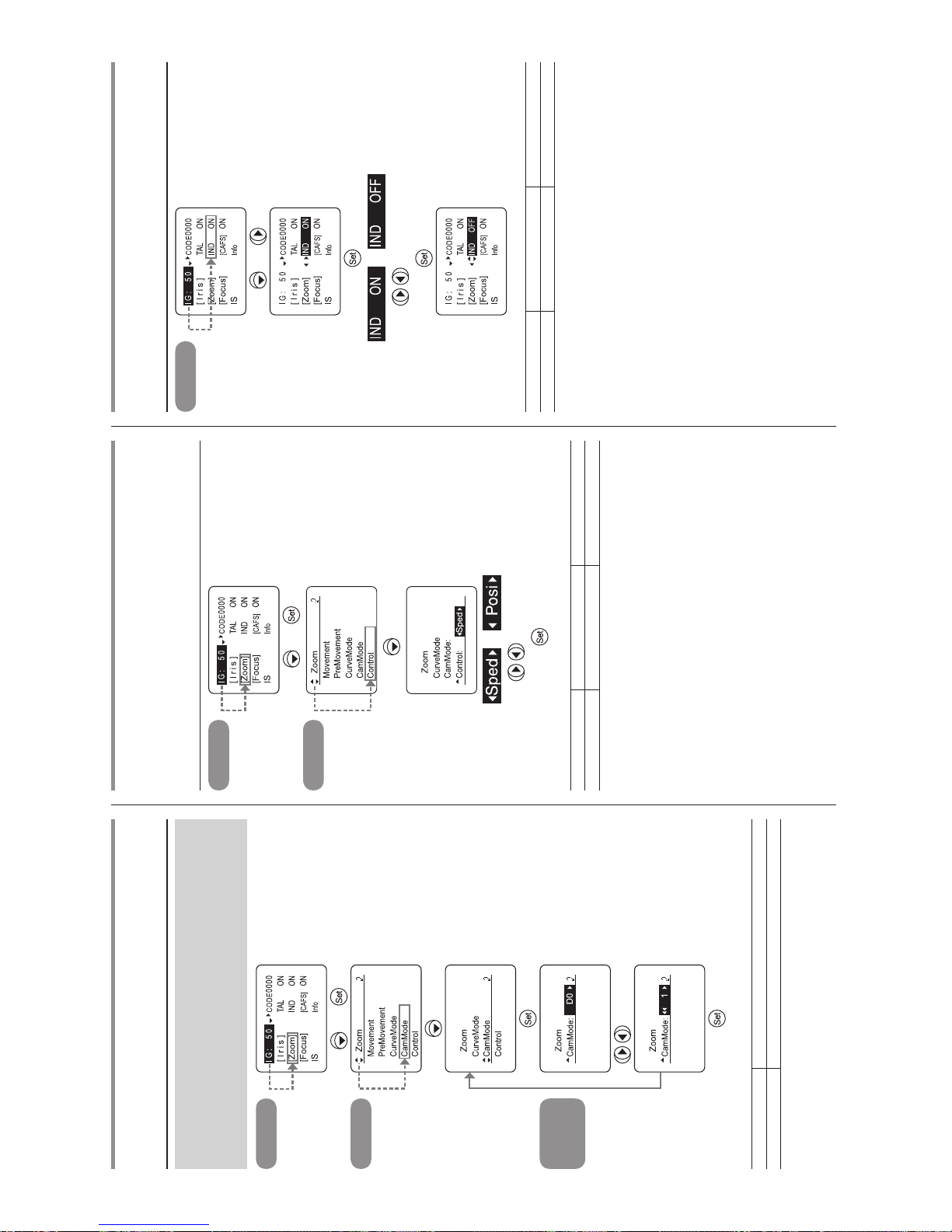
E8
[Zoom] – CamMode – Demand
CAM mode settings
The changes in the zoom view angle in relation to the zoom
control can be corrected.
No cor rection is made at the “0” se tting, and the maximum
correction is achieved at the “5” setting.
Top screen
× 2,
Zoom screen
× 4
CamMode
screen
to adjust
(to set to “1”)
Selection item
(D)
0 – 5
Function No correction Maximum correction
(D): Default value
[Zoom] – Control
Setting the servo mode type from the zoom demand
(Some models only indicate the currently set
servo mode, depending on the specications.)
Top screen
× 2,
Zoom screen
× 5
or
to select
Selection item
(D)
Sped Posi
Function Speed servo Position servo
(D): Default value
IND
Setting the indicator ON/OFF
Top screen
× 2,
or (ashing)
to select
(to set to OFF)
Selection item
(D)
ON OFF
Function Lighted Extinguished
(D): Default value
Page 59
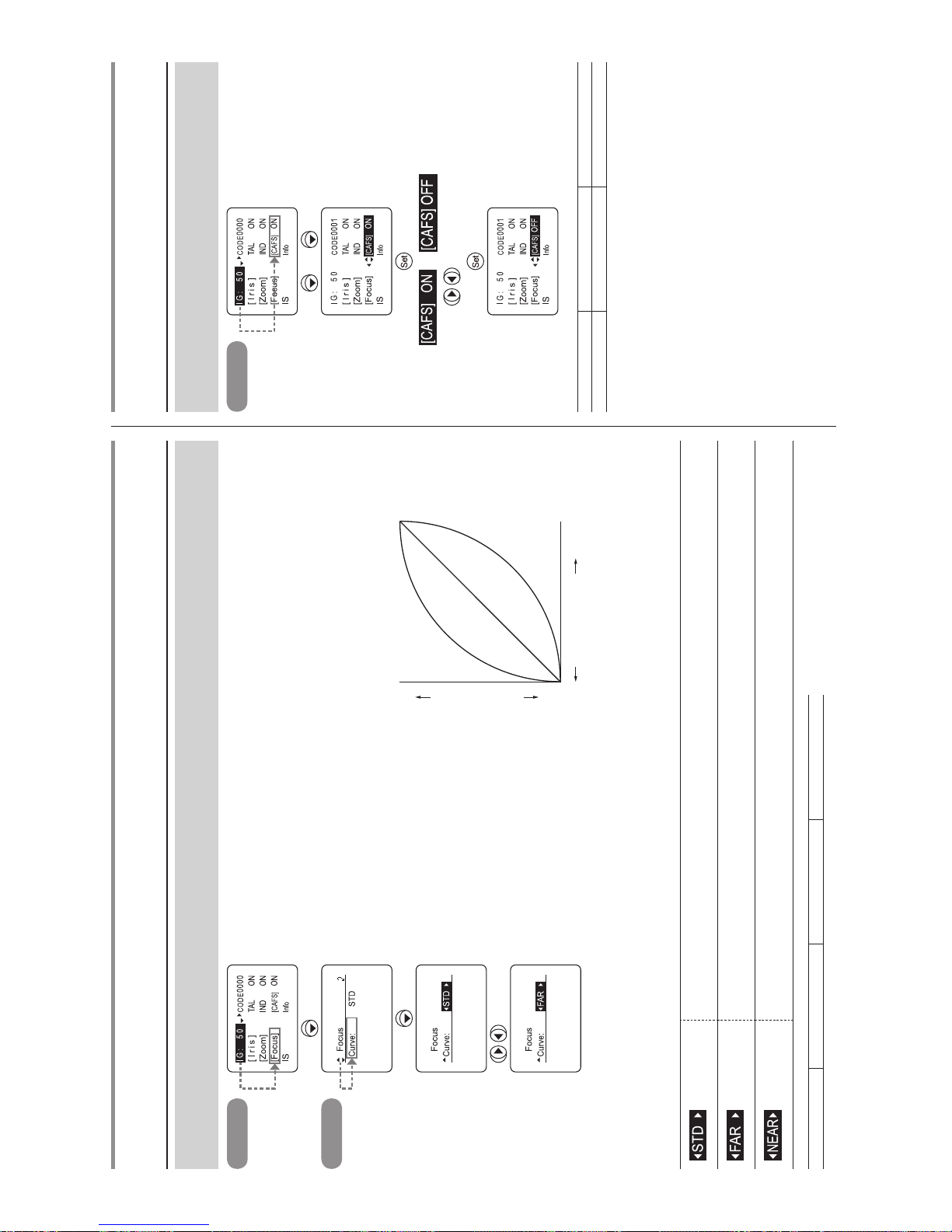
E9
Top screen
× 3
Focus screen
to select
(to set to FAR mode)
[Focus] – Curve
Focus demand curve characteristics
The focus demand curve characteristics can be set when focus control is performed from the camera. (However, this is not possible when
using serial data control.)
Selection item
(D)
STD FAR NEAR
(D): Default value
(Standard mode)
The Standard mode has the characteristics where the relationship between the rotation amount of the control
knob and the moving amount of the focus lens group is almost in linear.
(Far mode)
The Far mode facilitates focusing on an object in the far end, by making the far end curve characteristics
gentle to increase the far end resolution.
(Near mode)
Contrary to the Far mode, the Near mode facilitates focusing on an object in the near end, by making the
near end curve characteristics gentle to increase the near end resolution.
CAFS
CAFS setting
The changes in the view angle caused by focusing can reduce
to the zero level.
Top screen
× 3,
or (ashing)
to select
(to set to OFF)
Selection item
(D)
ON OFF
Function Enabled Disabled
(D): Default value
Innity
Focus position
Close range
FAR mode
STD mode
NEAR mode
Knob position
Page 60
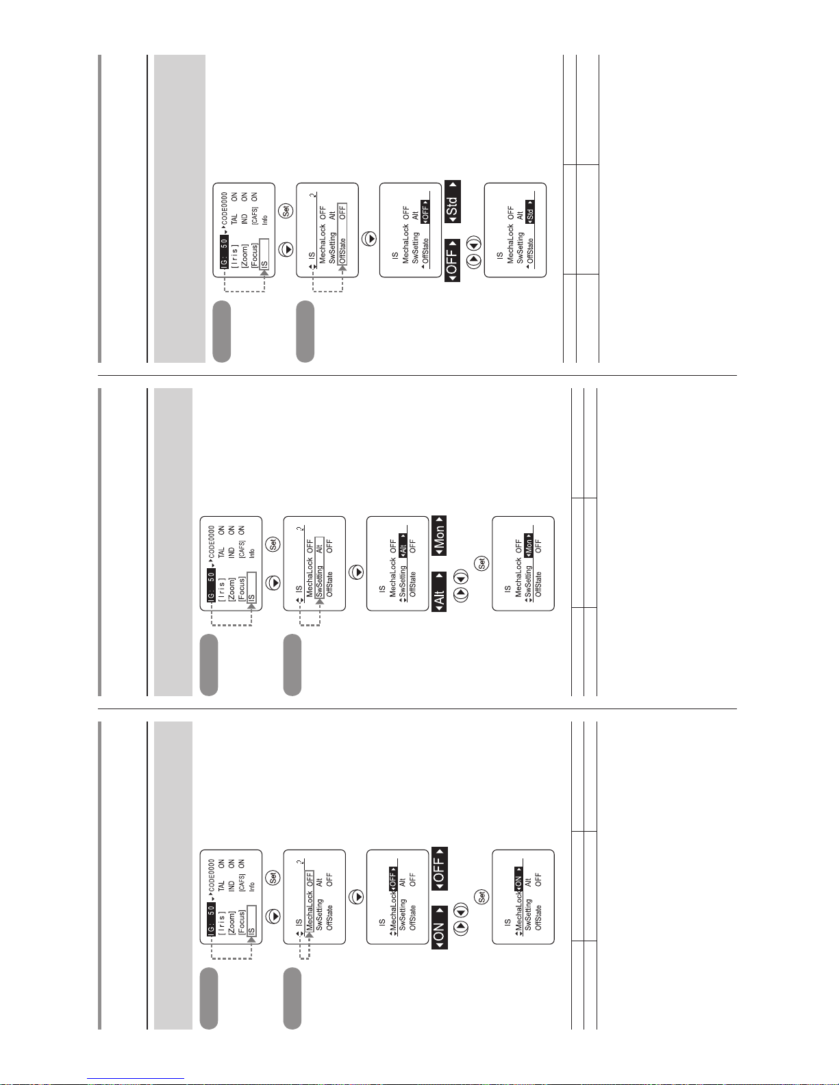
E10
IS – MechaLock
IS mechanical lock setting
The IS mechanism can be forcibly locked (mechanical lock)
even while the lens is shooting.
Top screen
× 4,
IS screen
or
to select
(to set to ON)
Selection item
(D)
OFF ON
Function IS mechanical lock off IS mechanical lock on
(D): Default value
IS – SWSetting
IS operation switch setting
The type of IS operation switch (Alt/Mon) that is used can be
selected.
Top screen
× 4,
IS screen
× 2
or
to select
Selection item
(D)
Alt Mon
Function Alternate type Momentary type
(D): Default value
IS – OffState
IS mode setting
The IS operation (Off/IS standard characteristics) when the IS
switch is set to OFF can be selected.
(Refer to page E15 of the Operation Manual.)
Top screen
× 4,
IS screen
× 3
or
Std
to select
(to set to Std)
Selection item
(D)
OFF Std
Function IS operation stop
IS operation standard
characteristics
(D): Default value
Page 61
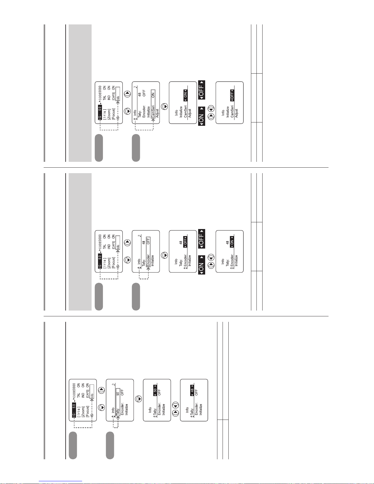
E11
Info – Tally
Tally lamp light quantity setting
Top screen
× 4,
Info screen
to adjust
(to set to “48”)
Selection item 01 – 99
Function Minimum light quantity Maximum light quantity
Default value: This is set as the default value at the factory prior to shipment.
Info – Encoder
Encoder output setting
The zoom and focus encoder output function can be enabled or
disabled. When it is enabled, signals are output from the virtual
connector. For details, contact with your dealer or Canon Inc.
Top screen
× 4,
Info screen
× 2
or
to select
(to set to ON)
Selection item
(D)
OFF ON
Function Output disabled Output enabled
(D): Default value
Info – CamSeri
Setting the camera serial communication to ON/OFF
The automatic identication setting of the interface between the
camera and the lens can be switched between ON (enabled) or
OFF (analog control).
Top screen
× 4,
Info screen
× 4
or
to select
Selection item
(D)
ON OFF
Function Enabled Disabled
(D): Default value
Page 62
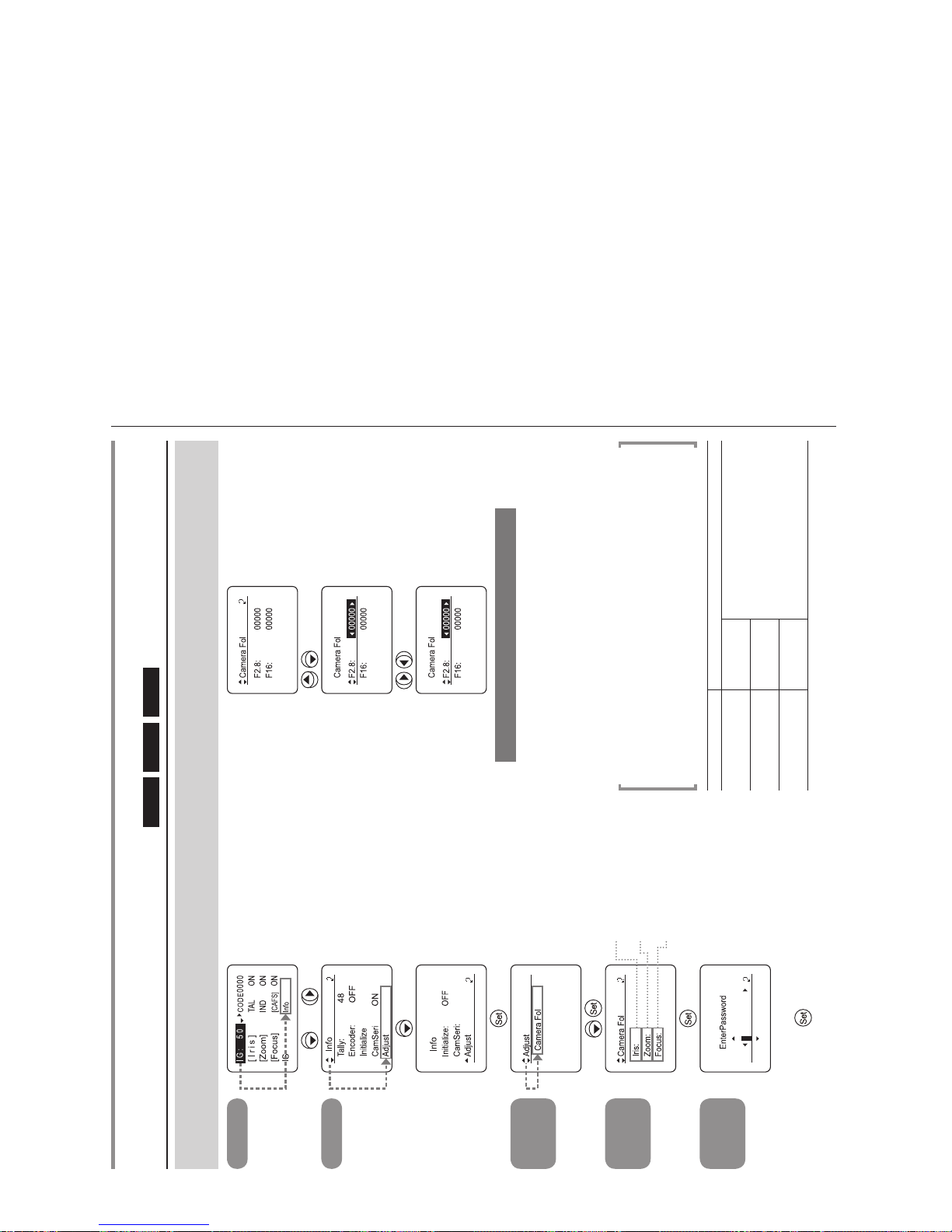
E12
Top screen
× 4,
Info screen
× 5
Adjust
screen
Camera Fol
screen
to set the iris voltage
to set the zoom voltage
to set the focus voltage
EnterPassword
screen
Enter the password
Info – Adjust – Camera Fol
Adjusting the Camera Fol Voltage
Iris
Zoom
Focus
The voltages sent back from the lens to the camera can be changed when it is necessary to change the lens side according to the
situation on the camera side (indicators, etc.). A password is required, so please contact the distributing agent or Canon Inc.
to select*
1
to adjust*
2
Press the DISPLAY switch to store the data.
*(Note 1): The data of the selected item is displayed.
When this operation is performed for the rst time, the factory default settings at the
time of shipment will be displayed. These are the values that have been adjusted
to each individual lens. Make a note of them in case they are to be restored.
*(Note 2): The numerical value is a relative value display.
Please note that making a radical change from the original value has the possibility
to inuence other equipment even though it possible to select from -32760 to 32760.
*(Note)
• The factory default settings at the time of shipment will not be restored even when
the reset operation is performed.
• The password is invalid when the power is turned off.
•
Perform password character input by locating the characters using the up and down buttons,
and moving from one character to another or making corrections using the left and right buttons.
Selection item Selection range
Iris
F2.8
-32760–( 0 )–32760
F16
Zoom
Wide
Tele
Focus
Near
Far
Reference: The numerical values in parentheses are the reference values for
the factory defaults at the time of shipment.
Page 63
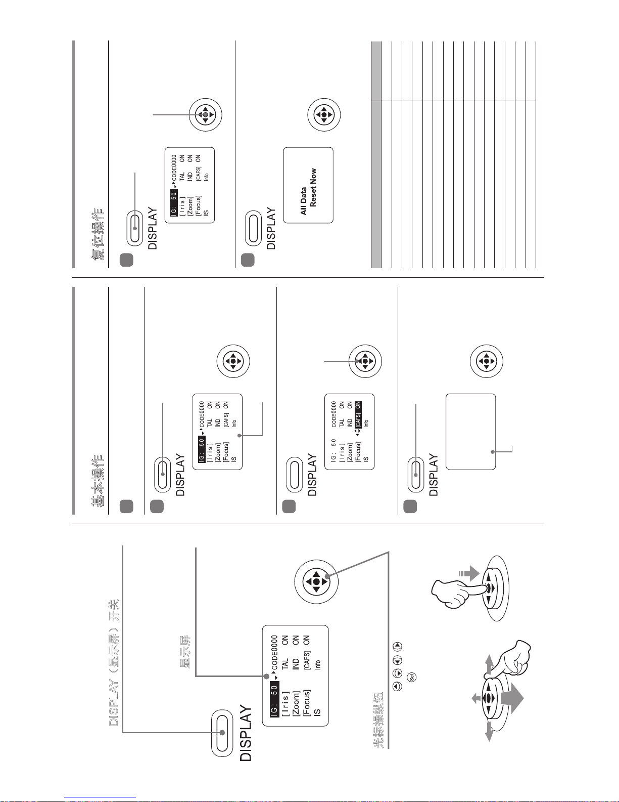
C1
基本操作
1
接通镜头电源。
2
3
4
复位操作
1
2
下表的数据被复位,返回缺省值。
按下 DISPLAY(显示屏)开关。
同时按 下 DISPLAY(显示 屏) 开关
和光标操纵钮,保持两秒钟。
按下 DISPLAY(显示屏)开关。
使用光标操纵钮,
进行各种设定。
显示屏闪亮。
显示屏熄灯,更改内容被保存。
设定项目 缺省值
CAFS 设定 ON
播放指示灯设定 ON
指示灯设定 ON
光圈补偿的 ON/OFF 切换设定 ON
光圈关闭检测的 ON/OFF 设定 工厂设定值
变焦伺服启动特性的设定 50
变焦伺服停止特性的设定 50
变焦机构端部停止特性的设定 91
各项预设变焦启动特性的设定 99
各项预设变焦停止特性的设定 91
模拟电动控制器曲线特性的设定 5
*
利用变焦电动控制器设定伺服模式类型 Sped
CAM 模式设定 0
聚焦电动控制器曲线特性 STD
播放指示灯光量设定 工厂设定值
* 只有 XJ60x 为“3”。
DISPLAY(显示屏)开关
启动 / 关闭(ON/OFF)显示屏的显示。
显示屏
停止操作状态持 续超过 2 分
钟以上时,显示消失。
光标操纵钮
向上下左右( )倾斜该钮移动光标。
按动中央部位(
),则可确定位置。
Page 64
OPERATION MANUAL
索 引
アイリス ............................................................................. 16
アイリスゲイン ..................................................................10
エクステンダー ..................................................................17
ズーム .................................................................................15
フォーカス ......................................................................
....1
5
フランジバック ....................................................................9
INDEX
BACK FOCUS ................................................................... E7
EXTENDER ..................................................................... E15
FOCUS ............................................................................ E13
IRIS.................................................................................. E14
IRIS GAIN .......................................................................... E8
ZOOM .............................................................................. E13
索 引
变焦 ....................................................................C13
光圈 ....................................................................C14
光圈增益 ...............................................................C8
后焦 ......................................................................C7
聚焦 ....................................................................C13
增距镜 .................................................................C
15
DISPLAY OPERATION MANUAL
索 引
インジケーター ....................................................................8
エンコーダー ...................................................................... 11
カメラシリアル ..................................................................11
初期化 ...................................................................................4
タリー ..........................................................................
........6
INDEX
CAMERA SERIAL .............................................................E11
ENCORDER .....................................................................E11
INDICATOR ....................................................................... E8
INITIALIZE ......................................................................... E4
TALLY ................................................................................ E6
索 引
编码器 .................................................................C11
播放 ......................................................................C6
初始化 ...................................................................C4
摄像机串行 ..........................................................C11
指示器 ...................................................................C8
Page 65

memo
Page 66

memo
Page 67

memo
Page 68

日本
キヤノンマーケティングジャパン株式会社
イメージングソリューション技術部
108-8011 東京都港区港南2-16-6
Tel:(03)3740-3305
Fax:(03)3740-3307
中国
佳能(中国)有限公司
北京市东城区金宝街89号
金宝大厦15层
邮编 100005
电话:+86(0)10-8513-9999
传真:+86(0)10-8513-9915
Singapore
Canon Singapore Pte. Ltd.
REG ICP Sales & Marketing Div.
1 HarbourFront Avenue
#04-01 Keppel Bay Tower
Singapore 098632
Tel:+65-6799-8888
Asia
Canon Inc.
ICP5 Planning & Marketing Div.
30-2, Shimomaruko 3-chome, Ohta-ku,
Tokyo, 146-8501, Japan
Tel:+81(0)3-3757-7453
Fax:+81(0)3-3757-7086
North & South America
Canon U.S.A., Inc.
Broadcast and Communications Div.
(Headquarters)
65 Challenger Road, Ridgeeld Park, NJ, 07660
Tel:+1(201)807-3300
Fax:+1(201)807-3333
Canada
Canon Canada, Inc.
Broadcast and Communications Div.
6390 Dixie Road, Mississauga, Ontario, L5T
1P7, Canada
Tel:+1(905)795-2012
Fax:+1(905)795-2087
Europe/Africa/Middle East
Canon Europe Ltd.
Broadcast Products Div.
3 The Square, Stockley Park, Uxbridge,
Middlesex, UB11 1ET, UK
Tel:+44(0)20-8588-8140
Fax:+44(0)20-8588-8929
Australia
Canon Australia Pty. Ltd.
Optical Products Division
1 Thomas Holt Drive, North Ryde, NSW
2113, Australia
Tel:+61(0)2-9805-2000
Fax:+61(0)2-9805-2444
Page 69

キヤノン株式会社
〒 146-8501 東京都大田区下丸子 3-30-2
仕様・外観・商品構成などはお断りなく変更することがあります。
CANON INC.
30-2, Shimomaruko 3-chome, Ohta-ku, Tokyo, 146-8501, Japan
Subject to change without notice.
进口商 :佳能(中国)有限公司
地址 :100005 北京市东城区金宝街 89 号 金宝大厦 15 层
规格・外观・商品构成等进行变更,恕不事先一一通知。
修订 :2012.12.1 原产地 : 日本
Pub No. B-IM-10060C 1212S ©2012.12 CANON INC. PRINTED IN JAPAN
 Loading...