

Page 1

DIGITAL VIDEO CAMCORDER
PAL
Instruction Manual
PUB. DIE-269
English
Introduction
Mini
Digital
Video
Cassette
Preparation
Recording
Customization
Playback
Editing
Using a
Memory Card
Additional
Information
Page 2
Introduction
Important Usage Instructions
WARNING:
TO REDUCE THE RISK OF ELECTRIC SHOCK, DO NOT REMOVE COVER (OR BACK). NO
USER SERVICEABLE PARTS INSIDE.
REFER SERVICING TO QUALIFIED SERVICE PERSONNEL.
WARNING:
TO REDUCE THE RISK OF FIRE OR ELECTRIC SHOCK, DO NOT EXPOSE THIS PRODUCT TO
RAIN OR MOISTURE.
CAUTION:
TO REDUCE THE RISK OF ELECTRIC SHOCK AND TO REDUCE ANNOYING INTERFERENCE,
USE THE RECOMMENDED ACCESSORIES ONLY.
CAUTION:
DISCONNECT THE MAINS PLUG FROM THE SUPPLY SOCKET WHEN NOT IN USE.
For Users in the UK
When replacing the fuse only a correctly rated approved type should be used and be sure to re-fit the fuse
cover.
The Mains plug is used as the disconnect device. The Mains plug shall remain readily operable to
disconnect the plug in case of an accident.
While using the compact power adapter, do not wrap it or cover it with a piece of cloth, and do not place it in
confined narrow spaces. Heat may build up, the plastic case may deform and it could result in electric shock
or fire.
CA-920 identification plate is located on the bottom.
• Use of CV-150F/CV-250F DV cable is necessary to comply with the technical requirement of EMC
Directive.
European Union (and EEA) only.
This symbol indicates that this product is not to be disposed of with your household waste, according
to the WEEE Directive (2002/96/EC) and your national law. This product should be handed over to a
designated collection point, e.g., on an authorized one-for-one basis when you buy a new similar
product or to an authorized collection site for recycling waste electrical and electronic equipment
(EEE). Improper handling of this type of waste could have a possible negative impact on the environment
and human health due to potentially hazardous substances that are generally associated with EEE. At the
same time, your cooperation in the correct disposal of this product will contribute to the effective usage of
natural resources. For more information about where you can drop off your waste equipment for recycling,
please contact your local city office, waste authority, approved WEEE scheme or your household waste
disposal service. For more information regarding return and recycling of WEEE products, please visit
www.canon-europe.com/environment
(EEA: Norway, Iceland and Liechtenstein)
.
2
Page 3
About this Manual
/ D
T
/ D
T
6
Thank you for purchasing the Canon XH G1/XH A1. Please read this manual carefully before you use
the camcorder and retain it for future reference. Should your camcorder fail to operate correctly, refer to
the Troubleshooting table ( 149).
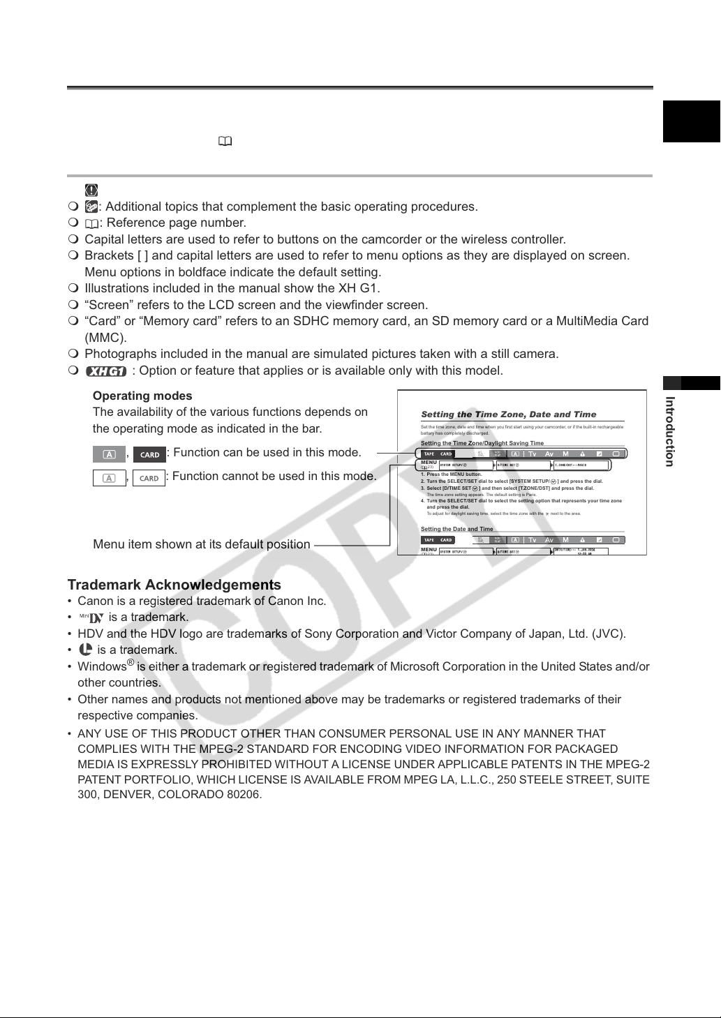
Conventions Used in this Manual
: Precautions related to the camcorder operation.
: Additional topics that complement the basic operating procedures.
: Reference page number.
Capital letters are used to refer to buttons on the camcorder or the wireless controller.
Brackets [ ] and capital letters are used to refer to menu options as they are displayed on screen.
Menu options in boldface indicate the default setting.
Illustrations included in the manual show the XH G1.
“Screen” refers to the LCD screen and the viewfinder screen.
“Card” or “Memory card” refers to an SDHC memory card, an SD memory card or a MultiMedia Card
(MMC).
Photographs included in the manual are simulated pictures taken with a still camera.
: Option or feature that applies or is available only with this model.
Operating modes
The availability of the various functions depends on
the operating mode as indicated in the bar.
, : Function can be used in this mode.
, : Function cannot be used in this mode.
Menu item shown at its default position
Setting the Time Zone, Date and Time
Set the time zone, date and time when you first start using your camcorder, or if the built-in rechargeable
battery has completely discharged.
Setting the Time Zone/Daylight Saving Time
MENU
SYSTEM
SET
UP
(23)
1. Press the MENU button.
2. Turn the SELECT/SET dial to select [SYSTEM SETUP/ ] and press the dial.
3. Select [D/TIME SET ] and then select [T.ZONE/DST] and press the dial.
The time zone setting appears. The default setting is Paris.
4. Turn the SELECT/SET dial to select the setting option that represents your time zone
and press the dial.
To adjust for daylight saving time, select the time zone with the next to the area.
Setting the Date and Time
MENU
SYSTEM
SET
UP
/TIME SE
/TIME SE
T.Z
ONE/DST•••PAR
DAT
E/T
IME••• 1.JAN.
IS
200
E
Introduction
Trademark Acknowledgements
• Canon is a registered trademark of Canon Inc.
• is a trademark.
• HDV and the HDV logo are trademarks of Sony Corporation and Victor Company of Japan, Ltd. (JVC).
• is a trademark.
•Windows
other countries.
• Other names and products not mentioned above may be trademarks or registered trademarks of their
respective companies.
• ANY USE OF THIS PRODUCT OTHER THAN CONSUMER PERSONAL USE IN ANY MANNER THAT
COMPLIES WITH THE MPEG-2 STANDARD FOR ENCODING VIDEO INFORMATION FOR PACKAGED
MEDIA IS EXPRESSLY PROHIBITED WITHOUT A LICENSE UNDER APPLICABLE PATENTS IN THE MPEG-2
PATENT PORTFOLIO, WHICH LICENSE IS AVAILABLE FROM MPEG LA, L.L.C., 250 STEELE STREET, SUITE
300, DENVER, COLORADO 80206.
®
is either a trademark or registered trademark of Microsoft Corporation in the United States and/or
3
Page 4

About the HD/HDV and SD/DV Specifications
V
Throughout the manual we will distinguish between the video signal standards used by the camera
section, and the recording standards used by the recorder section. The video signal can be set to HD
(high definition) or SD (standard definition) specifications. The recording standard on the tape will be
HDV or DV, respectively.
Camera Section HD/SD
HD/SD SDI Terminal HD/SD
Recorder Section HDV/DV
Playback Signal HDV/DV
HDV/DV Terminal HDV/D
4
Page 5
Contents
Introduction
Important Usage Instructions............................................................................................................................. 2
About this Manual.............................................................................................................................................. 3
Checking the Supplied Accessories .................................................................................................................. 7
Components Guide............................................................................................................................................ 8
Preparations
Preparing the Power Supply............................................................................................................................ 13
Preparing the Camcorder ................................................................................................................................ 16
Using the Wireless Controller .......................................................................................................................... 20
Loading/Removing a Cassette ........................................................................................................................ 21
Inserting/Removing a Memory Card................................................................................................................ 22
Changing Settings with the MENU Button....................................................................................................... 23
Setting the Time Zone, Date and Time............................................................................................................ 24
Recording
Recording ........................................................................................................................................................ 25
Selecting the Signal Standard and Aspect Ratio............................................................................................. 29
Locating the End of the Last Scene ................................................................................................................ 30
Zooming .......................................................................................................................................................... 31
Adjusting the Focus ......................................................................................................................................... 33
Using the ND Filter .......................................................................................................................................... 37
Selecting the Frame Rate................................................................................................................................ 38
Setting the Time Code..................................................................................................................................... 39
Synchronizing the Camcorder’s Time Code ..................................................................................... 40
Setting the User Bit.......................................................................................................................................... 42
Audio Recording .............................................................................................................................................. 43
Image Stabilizer............................................................................................................................................... 47
Using the Programmed AE Modes .................................................................................................................. 48
Recording in the Shutter-Priority (Tv) Mode .................................................................................................... 51
Recording in the Aperture-Priority (Av) Mode.................................................................................................. 52
Recording in the Manual Mode........................................................................................................................ 53
Adjusting the Exposure.................................................................................................................................... 54
Using AE Shift ................................................................................................................................................. 55
Adjusting the Gain ........................................................................................................................................... 56
Setting the White Balance ............................................................................................................................... 58
Using the Zebra Pattern .................................................................................................................................. 60
Using the Color Correction .............................................................................................................................. 61
Using the Skin Detail Function ........................................................................................................................ 63
Using the Sky Detail ........................................................................................................................................ 64
Using the Clear Scan Function........................................................................................................................ 65
Using the Custom Keys ................................................................................................................................... 66
Recording Color Bars/Audio Reference Signal ............................................................................................... 69
Using the Digital Video Control........................................................................................................................ 70
Other Camcorder Functions/Settings .............................................................................................................. 71
Customization
Using the Custom Preset................................................................................................................................. 72
Using the Customized Functions..................................................................................................................... 79
Customizing the On-Screen Displays.............................................................................................................. 86
Playback
Playing Back a Tape ........................................................................................................................................ 91
E
Introduction
5
Page 6
Connecting to a Monitor/TV............................................................................................................................. 93
SD
Audio Output ............................................................................................................................................ 97
Returning to a Pre-marked Position ................................................................................................................ 98
Index Search ................................................................................................................................................... 99
Date Search .................................................................................................................................................. 100
Displaying the Data Code.............................................................................................................................. 101
Changing the Remote Sensor Mode ............................................................................................................. 102
Editing
Recording an External Video Signal (Analog Line-In, HDV/DV In)................................................................ 103
Converting Analog Signals into Digital Signals (Analog-Digital Converter) ................................................... 105
Connecting to a Computer (IEEE1394) ......................................................................................................... 106
Using a Memory Card
Selecting the Image Quality/Size................................................................................................................... 107
File Numbers ................................................................................................................................................. 108
Recording Still Images on a Memory Card .................................................................................................... 109
Selecting the Drive Mode .............................................................................................................................. 112
Selecting the Metering Method...................................................................................................................... 114
Using an Optional Flash ................................................................................................................................ 115
Reviewing a Still Image Right after Recording .............................................................................................. 116
Playing Back Still Images from a Memory Card ............................................................................................ 117
Erasing Images.............................................................................................................................................. 119
Protecting Images.......................................................................................................................................... 120
Initializing a Memory Card ............................................................................................................................. 121
Print Order Settings ....................................................................................................................................... 122
Additional Information
Settings Retained at Power Off or STANDBY Mode ..................................................................................... 123
Menu Options and Default Settings............................................................................................................... 124
Screen Displays............................................................................................................................................. 139
List of Messages............................................................................................................................................ 142
Maintenance/Others ...................................................................................................................................... 143
Troubleshooting............................................................................................................................................. 149
System Diagram............................................................................................................................................ 151
Optional Accessories..................................................................................................................................... 152
Specifications ................................................................................................................................................ 154
Index.............................................................................................................................................................. 156
6
Page 7
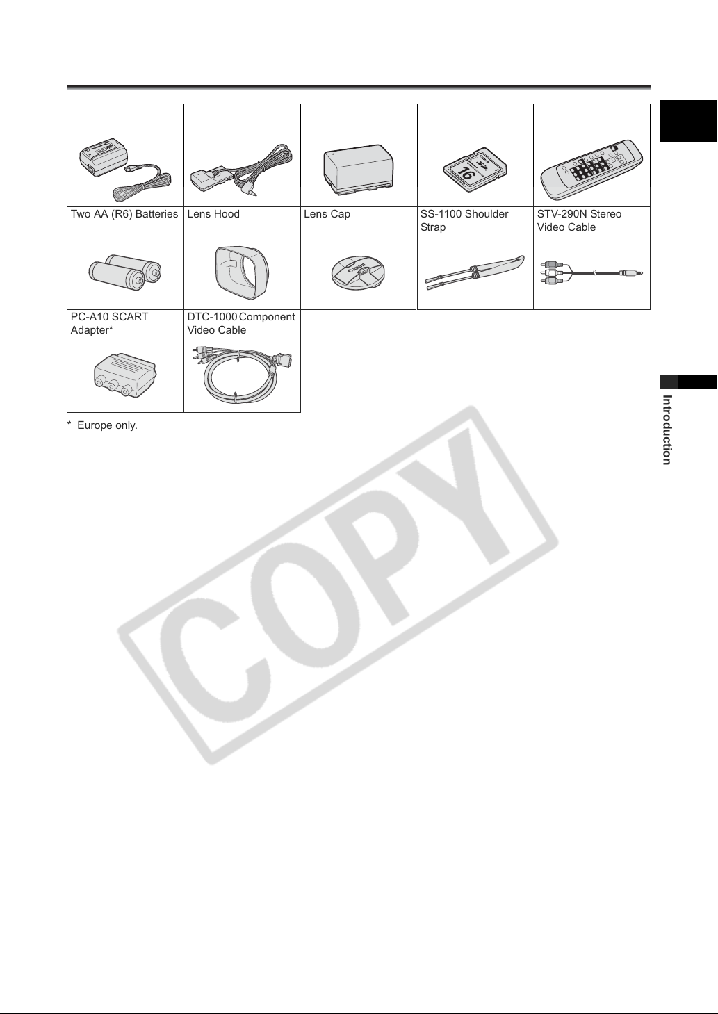
Checking the Supplied Accessories
CA-920 Compact
Power Adapter
Two AA (R6) Batteries Lens Hood Lens Cap SS-1100 Shoulder
PC-A10 SCART
Adapter*
* Europe only.
DC-920 DC Coupler BP-950G Battery Pack SDC-16M SD Memory
Card
Strap
DTC-1000 Component
Video Cable
WL-D5000 Wireless
Controller
STV-290N Stereo
Video Cable
E
Introduction
7
Page 8
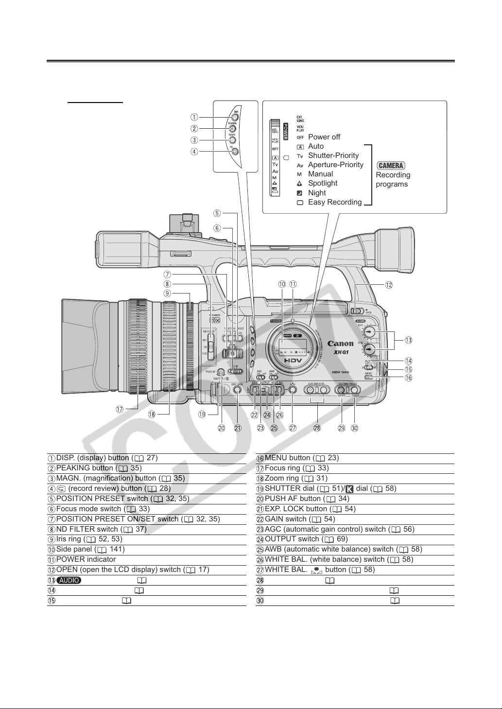
Components Guide
XH G1/XH A1
Left side view
POWER dial
External control mode
VCR/PLAY mode
Power off
Auto
Shutter-Priority
Aperture-Priority
Manual
Spotlight
Night
Easy Recording
Recording
programs
DISP. (display) button ( 27)
PEAKING button ( 35)
MAGN. (magnification) button ( 35)
(record review) button ( 28)
POSITION PRESET switch ( 32, 35)
Focus mode switch ( 33)
POSITION PRESET ON/SET switch ( 32, 35)
ND FILTER switch ( 37)
Iris ring ( 52, 53)
Side panel ( 141)
POWER indicator
OPEN (open the LCD display) switch ( 17)
CH1/CH2 dials ( 45)
AUDIO LEVEL switch ( 45)
SELECT/SET dial ( 23)
8
MENU button ( 23)
Focus ring ( 33)
Zoom ring ( 31)
SHUTTER dial ( 51)/ dial ( 58)
PUSH AF button ( 34)
EXP. LOCK button ( 54)
GAIN switch ( 54)
AGC (automatic gain control) switch ( 56)
OUTPUT switch ( 69)
AWB (automatic white balance) switch ( 58)
WHITE BAL. (white balance) switch ( 58)
WHITE BAL. button ( 58)
CUSTOM KEYS ( 66)
CUSTOM PRESET ON/OFF button ( 77)
CUSTOM PRESET SELECT button ( 77)
Page 9

Right side view
E
Introduction
Grip zoom lever ( 31)
PHOTO button ( 109)
Zoom speed adjustment dial ( 31)
ZOOM SPEED switch ( 31)
/ (card/tape) switch ( 109)
VIDEO2 terminal ( 95)
TIME CODE switch* ( 40)
LOCK switch ( 26)
MIC (external microphone) terminal ( 43)
*only.
XLR MIC ATT. switches ( 44)
LINE/MIC switch ( 44)
Input channel selection switch ( 44)
Lens hood ( 19)
Lens hood locking screw ( 19)
switches ( 44)
CH1 input terminal ( 44)
CH2 input terminal ( 44)
Cassette compartment ( 21)
9
Page 10
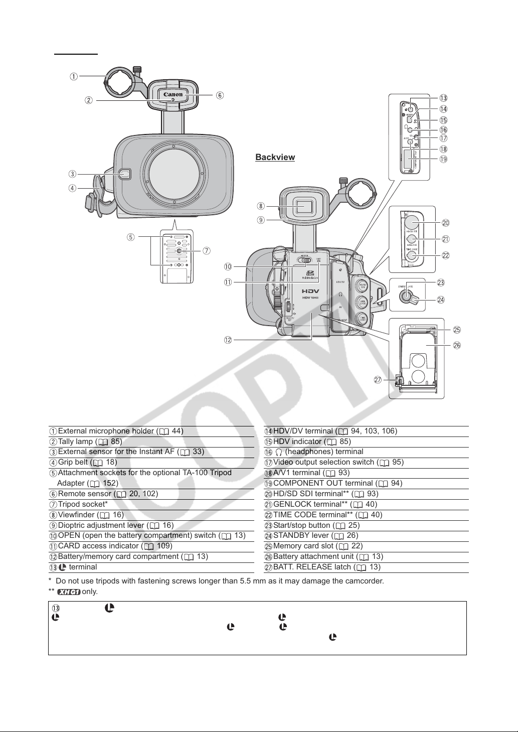
Front view
Backview
External microphone holder ( 44)
Tally lamp ( 85)
External sensor for the Instant AF ( 33)
Grip belt ( 18)
Attachment sockets for the optional TA-100 Tripod
Adapter ( 152)
Remote sensor ( 20, 102)
Tripod socket*
Viewfinder ( 16)
Dioptric adjustment lever ( 16)
OPEN (open the battery compartment) switch ( 13)
CARD access indicator ( 109)
Battery/memory card compartment ( 13)
terminal
* Do not use tripods with fastening screws longer than 5.5 mm as it may damage the camcorder.
** only.
HDV/DV terminal ( 94, 103, 106)
HDV indicator ( 85)
(headphones) terminal
Video output selection switch ( 95)
A/V1 terminal ( 93)
COMPONENT OUT terminal ( 94)
HD/SD SDI terminal** ( 93)
GENLOCK terminal** ( 40)
TIME CODE terminal** ( 40)
Start/stop button ( 25)
STANDBY lever ( 26)
Memory card slot ( 22)
Battery attachment unit ( 13)
BATT. RELEASE latch ( 13)
About the Terminal
(LANC) stands for Local Application Control Bus System. The terminal allows you to connect and control
connected devices. Connect only devices with the mark to the terminal.
Operation cannot be guaranteed for connections with devices not bearing the mark.
Some buttons of connected devices may not operate or may operate differently than the buttons on the camcorder.
10
Page 11
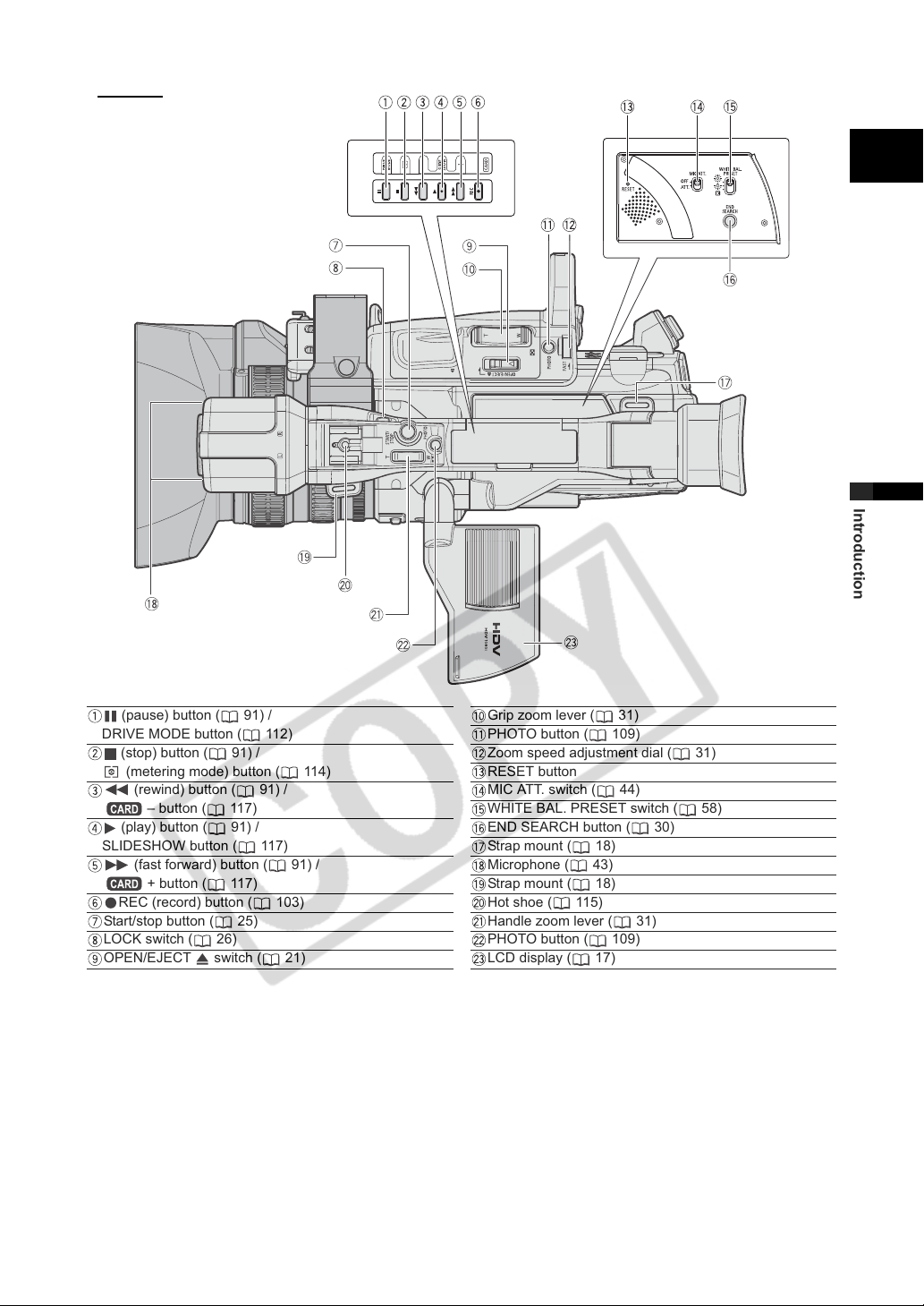
Top view
E
Introduction
(pause) button ( 91) /
DRIVE MODE button ( 112)
(stop) button ( 91) /
(metering mode) button ( 114)
(rewind) button ( 91) /
– button ( 117)
(play) button ( 91) /
SLIDESHOW button ( 117)
(fast forward) button ( 91) /
+ button ( 117)
REC (record) button ( 103)
Start/stop button ( 25)
LOCK switch ( 26)
OPEN/EJECT switch ( 21)
Grip zoom lever ( 31)
PHOTO button ( 109)
Zoom speed adjustment dial ( 31)
RESET button
MIC ATT. switch ( 44)
WHITE BAL. PRESET switch ( 58)
END SEARCH button ( 30)
Strap mount ( 18)
Microphone ( 43)
Strap mount ( 18)
Hot shoe ( 115)
Handle zoom lever ( 31)
PHOTO button ( 109)
LCD display ( 17)
11
Page 12
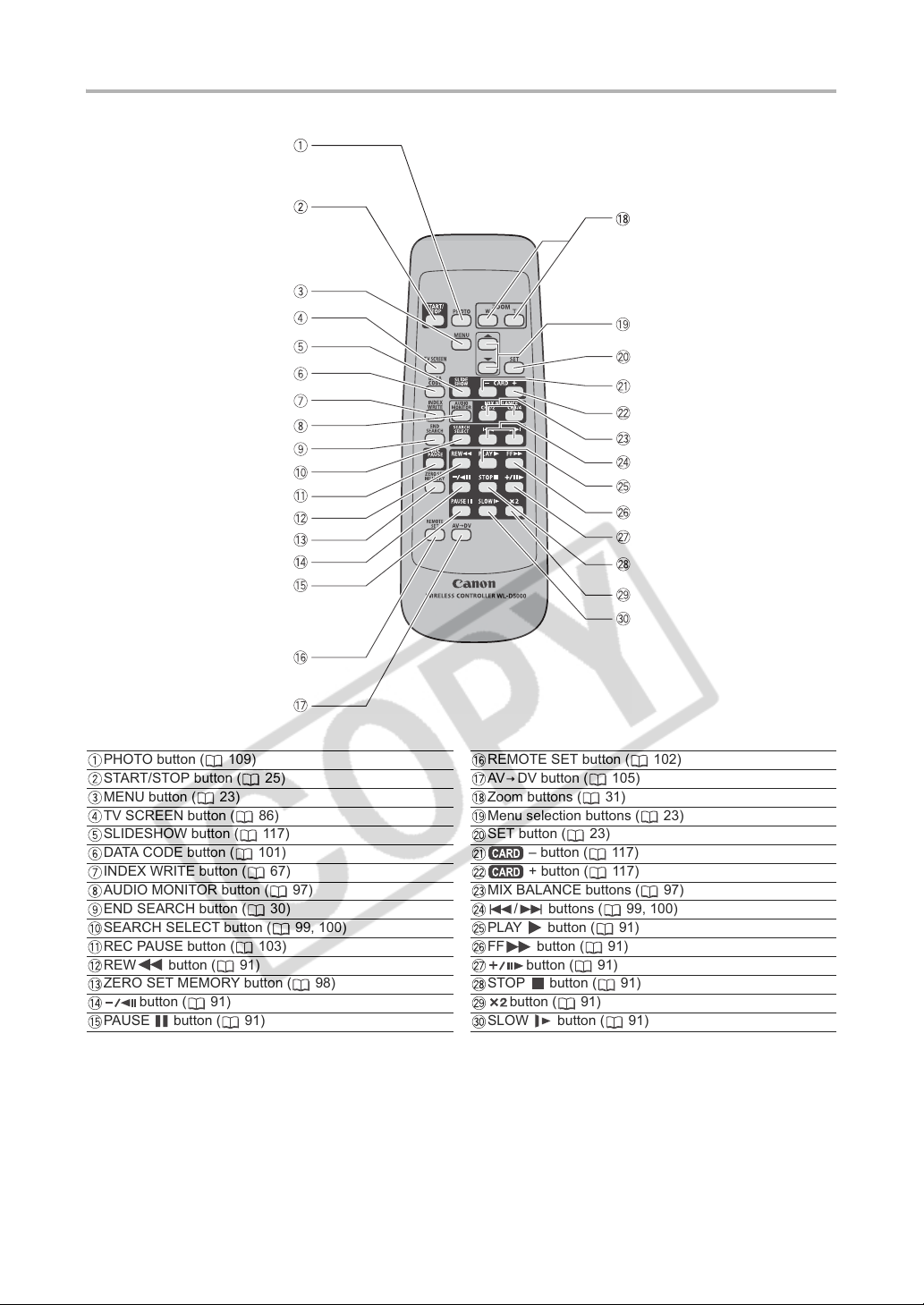
WL-D5000 Wireless Controller
PHOTO button ( 109)
START/STOP button ( 25)
MENU button ( 23)
TV SCREEN button ( 86)
SLIDESHOW button ( 117)
DATA CODE button ( 101)
INDEX WRITE button ( 67)
AUDIO MONITOR button ( 97)
END SEARCH button ( 30)
SEARCH SELECT button ( 99, 100)
REC PAUSE button ( 103)
REW button ( 91)
ZERO SET MEMORY button ( 98)
button ( 91)
PAUSE button ( 91)
12
REMOTE SET button ( 102)
AV DV button ( 105)
Zoom buttons ( 31)
Menu selection buttons ( 23)
SET button ( 23)
– button ( 117)
+ button ( 117)
MIX BALANCE buttons ( 97)
/ buttons ( 99, 100)
PLAY button ( 91)
FF button ( 91)
button ( 91)
STOP button ( 91)
button ( 91)
SLOW button ( 91)
Page 13
Preparations
Preparing the Power Supply
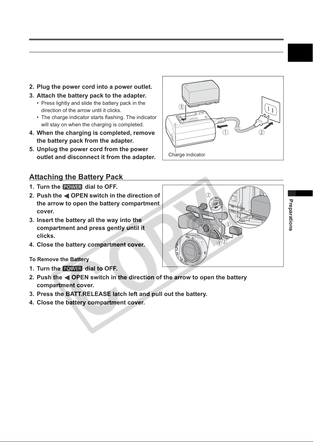
Charging the Battery Pack
Disconnect the DC coupler from the power adapter before charging. Remove the terminal cover of the
battery pack.
1. Connect the power cord to the adapter.
2. Plug the power cord into a power outlet.
3. Attach the battery pack to the adapter.
• Press lightly and slide the battery pack in the
direction of the arrow until it clicks.
• The charge indicator starts flashing. The indicator
will stay on when the charging is completed.
4. When the charging is completed, remove
the battery pack from the adapter.
5. Unplug the power cord from the power
outlet and disconnect it from the adapter.
Charge indicator
Attaching the Battery Pack
1. Turn the dial to OFF.
2. Push the OPEN switch in the direction of
the arrow to open the battery compartment
cover.
3. Insert the battery all the way into the
compartment and press gently until it
clicks.
4. Close the battery compartment cover.
E
Preparations
To Remove the Battery
1. Turn the dial to OFF.
2. Push the OPEN switch in the direction of the arrow to open the battery
compartment cover.
3. Press the BATT.RELEASE latch left and pull out the battery.
4. Close the battery compartment cover.
13
Page 14
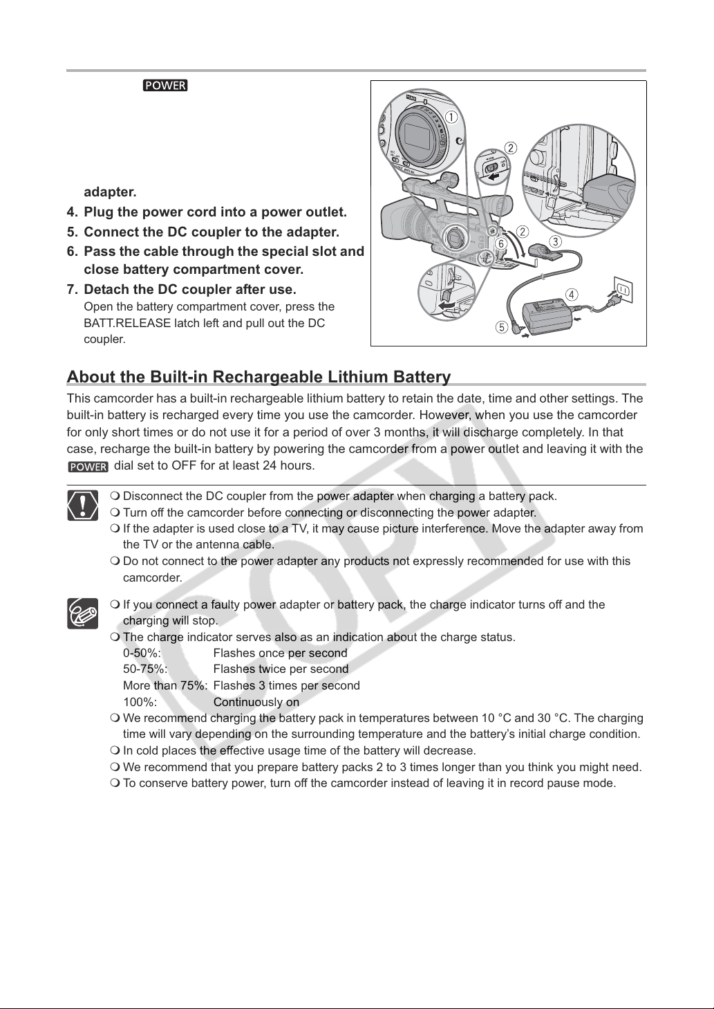
Using a Household Power Outlet
1. Turn the dial to OFF.
2. Attach the DC coupler to the camcorder.
Open the battery compartment cover and slide the
DC coupler all the way into the compartment and
press gently until it clicks.
3. Connect the power cord to the power
adapter.
4. Plug the power cord into a power outlet.
5. Connect the DC coupler to the adapter.
6. Pass the cable through the special slot and
close battery compartment cover.
7. Detach the DC coupler after use.
Open the battery compartment cover, press the
BATT.RELEASE latch left and pull out the DC
coupler.
About the Built-in Rechargeable Lithium Battery
This camcorder has a built-in rechargeable lithium battery to retain the date, time and other settings. The
built-in battery is recharged every time you use the camcorder. However, when you use the camcorder
for only short times or do not use it for a period of over 3 months, it will discharge completely. In that
case, recharge the built-in battery by powering the camcorder from a power outlet and leaving it with the
dial set to OFF for at least 24 hours.
Disconnect the DC coupler from the power adapter when charging a battery pack.
Turn off the camcorder before connecting or disconnecting the power adapter.
If the adapter is used close to a TV, it may cause picture interference. Move the adapter away from
the TV or the antenna cable.
Do not connect to the power adapter any products not expressly recommended for use with this
camcorder.
If you connect a faulty power adapter or battery pack, the charge indicator turns off and the
charging will stop.
The charge indicator serves also as an indication about the charge status.
0-50%: Flashes once per second
50-75%: Flashes twice per second
More than 75%: Flashes 3 times per second
100%: Continuously on
We recommend charging the battery pack in temperatures between 10 °C and 30 °C. The charging
time will vary depending on the surrounding temperature and the battery’s initial charge condition.
In cold places the effective usage time of the battery will decrease.
We recommend that you prepare battery packs 2 to 3 times longer than you think you might need.
To conserve battery power, turn off the camcorder instead of leaving it in record pause mode.
14
Page 15
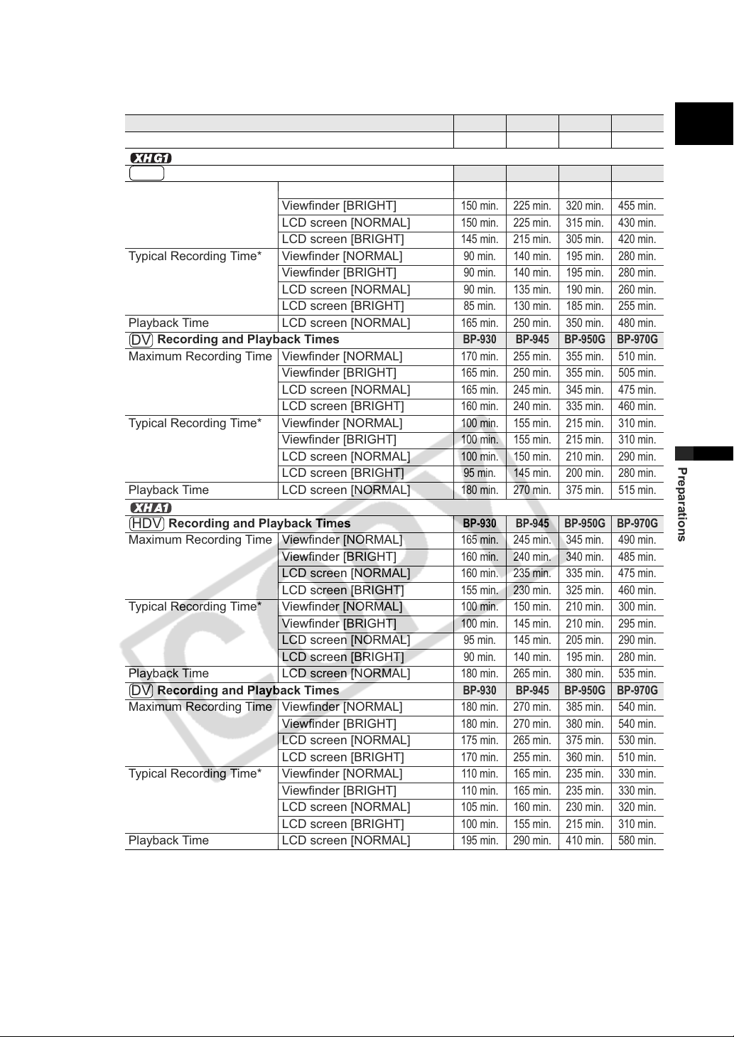
Charging, Recording and Playback Times
The following times are approximate and vary according to the charging, recording and playback
conditions.
Battery Pack
Charging Time with the CA-920 Compact Power Adapter
BP-930 BP-945 BP-950G BP-970G
145 min. 220 min. 235 min. 320 min.
E
Recording and Playback Times
HDV
Maximum Recording Time Viewfinder [NORMAL]
Viewfinder [BRIGHT]
LCD screen [NORMAL]
LCD screen [BRIGHT]
Typical Recording Time* Viewfinder [NORMAL]
Viewfinder [BRIGHT]
LCD screen [NORMAL]
LCD screen [BRIGHT]
Playback Time LCD screen [NORMAL]
Recording and Playback Times
DV
Maximum Recording Time Viewfinder [NORMAL]
Viewfinder [BRIGHT]
LCD screen [NORMAL]
LCD screen [BRIGHT]
Typical Recording Time* Viewfinder [NORMAL]
Viewfinder [BRIGHT]
LCD screen [NORMAL]
LCD screen [BRIGHT]
Playback Time LCD screen [NORMAL]
Recording and Playback Times
HDV
Maximum Recording Time Viewfinder [NORMAL]
Viewfinder [BRIGHT]
LCD screen [NORMAL]
LCD screen [BRIGHT]
Typical Recording Time* Viewfinder [NORMAL]
Viewfinder [BRIGHT]
LCD screen [NORMAL]
LCD screen [BRIGHT]
Playback Time LCD screen [NORMAL]
Recording and Playback Times
DV
Maximum Recording Time Viewfinder [NORMAL]
Viewfinder [BRIGHT]
LCD screen [NORMAL]
LCD screen [BRIGHT]
Typical Recording Time* Viewfinder [NORMAL]
Viewfinder [BRIGHT]
LCD screen [NORMAL]
LCD screen [BRIGHT]
Playback Time LCD screen [NORMAL]
* Approximate times for recording with repeated operations such as start/stop, zooming, power on/off. Actual
time may be shorter.
BP-930 BP-945 BP-950G BP-970G
150 min. 230 min. 320 min. 460 min.
150 min. 225 min. 320 min. 455 min.
150 min. 225 min. 315 min. 430 min.
145 min. 215 min. 305 min. 420 min.
90 min. 140 min. 195 min. 280 min.
90 min. 140 min. 195 min. 280 min.
90 min. 135 min. 190 min. 260 min.
85 min. 130 min. 185 min. 255 min.
165 min. 250 min. 350 min. 480 min.
BP-930 BP-945 BP-950G BP-970G
170 min. 255 min. 355 min. 510 min.
165 min. 250 min. 355 min. 505 min.
165 min. 245 min. 345 min. 475 min.
160 min. 240 min. 335 min. 460 min.
100 min. 155 min. 215 min. 310 min.
100 min. 155 min. 215 min. 310 min.
100 min. 150 min. 210 min. 290 min.
95 min. 145 min. 200 min. 280 min.
180 min. 270 min. 375 min. 515 min.
BP-930 BP-945 BP-950G BP-970G
165 min. 245 min. 345 min. 490 min.
160 min. 240 min. 340 min. 485 min.
160 min. 235 min. 335 min. 475 min.
155 min. 230 min. 325 min. 460 min.
100 min. 150 min. 210 min. 300 min.
100 min. 145 min. 210 min. 295 min.
95 min. 145 min. 205 min. 290 min.
90 min. 140 min. 195 min. 280 min.
180 min. 265 min. 380 min. 535 min.
BP-930 BP-945 BP-950G BP-970G
180 min. 270 min. 385 min. 540 min.
180 min. 270 min. 380 min. 540 min.
175 min. 265 min. 375 min. 530 min.
170 min. 255 min. 360 min. 510 min.
110 min. 165 min. 235 min. 330 min.
110 min. 165 min. 235 min. 330 min.
105 min. 160 min. 230 min. 320 min.
100 min. 155 min. 215 min. 310 min.
195 min. 290 min. 410 min. 580 min.
Preparations
15
Page 16
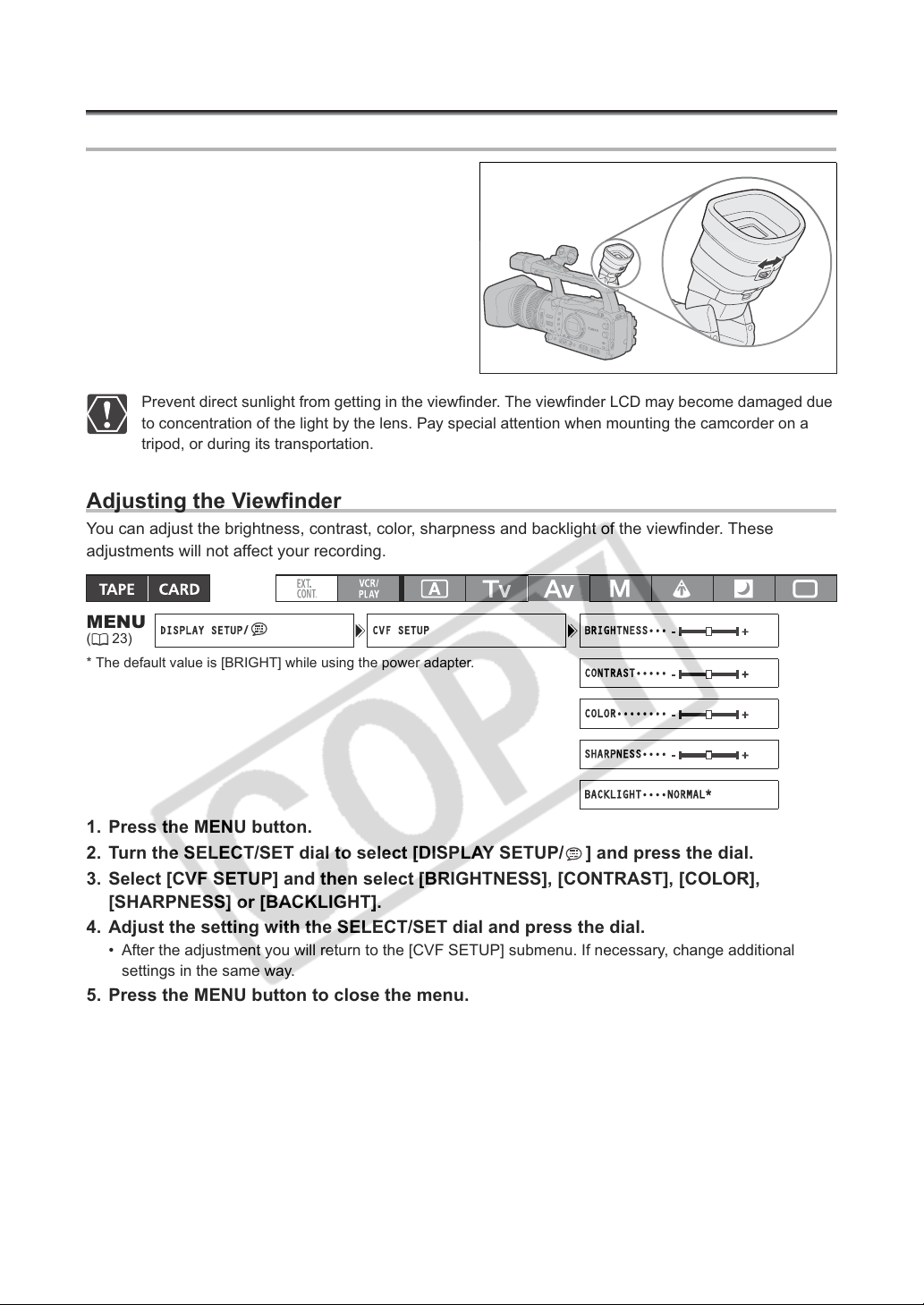
Preparing the Camcorder
DISPLAY SETUP/ CVF SETUP BRIGHTNESS•••
CONTRAST•••••
COLOR••••••••
SHARPNESS••••
BACKLIGHT••••NORMAL*
Dioptric Adjustment
Turn on the camcorder and adjust the dioptric
adjustment lever.
Prevent direct sunlight from getting in the viewfinder. The viewfinder LCD may become damaged due
to concentration of the light by the lens. Pay special attention when mounting the camcorder on a
tripod, or during its transportation.
Adjusting the Viewfinder
You can adjust the brightness, contrast, color, sharpness and backlight of the viewfinder. These
adjustments will not affect your recording.
MENU
(23)
* The default value is [BRIGHT] while using the power adapter.
1. Press the MENU button.
2. Turn the SELECT/SET dial to select [DISPLAY SETUP/ ] and press the dial.
3. Select [CVF SETUP] and then select [BRIGHTNESS], [CONTRAST], [COLOR],
[SHARPNESS] or [BACKLIGHT].
4. Adjust the setting with the SELECT/SET dial and press the dial.
• After the adjustment you will return to the [CVF SETUP] submenu. If necessary, change additional
settings in the same way.
5. Press the MENU button to close the menu.
16
Page 17

Using the LCD Display
DISPLAY SETUP/ LCD SETUP BRIGHTNESS•••
CONTRAST•••••
COLOR••••••••
SHARPNESS••••
BACKLIGHT••••NORMAL*
1. Slide the OPEN switch in the direction of the arrow to unlock the LCD panel.
2. Pull out the LCD panel.
3. Rotate the LCD panel and adjust it to the desired position.
You can change the LCD panel to black & white display ( 18).
By default, the viewfinder display is turned off while you use the LCD panel. However, you can
change the settings to be able to use both displays simultaneously ( 18).
E
Adjusting the LCD Panel
You can adjust the brightness, contrast, color, sharpness and backlight of the LCD Panel. These
adjustments will not affect your recording.
MENU
(23)
* The default value is [BRIGHT] while using the power adapter.
1. Press the MENU button.
2. Turn the SELECT/SET dial to select [DISPLAY SETUP/ ] and press the dial.
3. Select [LCD SETUP] and then select [BRIGHTNESS], [CONTRAST], [COLOR],
4. Adjust the setting with the SELECT/SET dial and press the dial.
5. Press the MENU button to close the menu.
[SHARPNESS] or [BACKLIGHT].
• After the adjustment you will return to the [LCD SETUP] submenu. Change additional settings in the
same way as necessary.
Preparations
17
Page 18
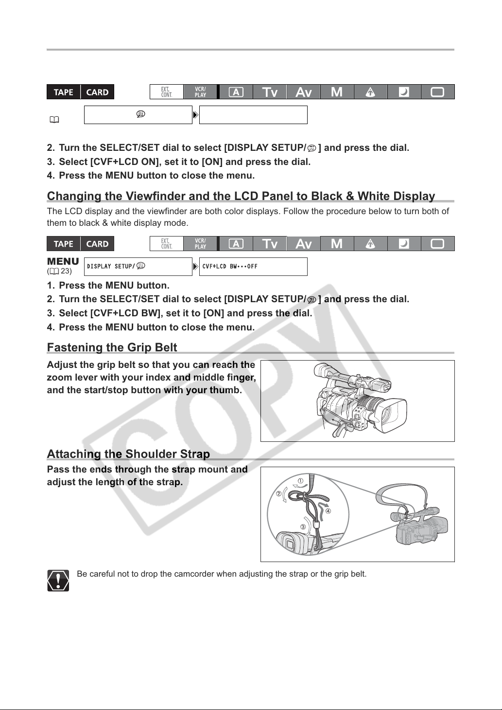
Using the Viewfinder and the LCD Panel Simultaneously
DISPLAY SETUP/ CVF+LCD ON•••OFF
DISPLAY SETUP/ CVF+LCD BW•••OFF
By default, the viewfinder display is turned off while you use the LCD panel. Follow the procedure below
to use both of them simultaneously.
MENU
(23)
1. Press the MENU button.
2. Turn the SELECT/SET dial to select [DISPLAY SETUP/ ] and press the dial.
3. Select [CVF+LCD ON], set it to [ON] and press the dial.
4. Press the MENU button to close the menu.
Changing the Viewfinder and the LCD Panel to Black & White Display
The LCD display and the viewfinder are both color displays. Follow the procedure below to turn both of
them to black & white display mode.
MENU
(23)
1. Press the MENU button.
2. Turn the SELECT/SET dial to select [DISPLAY SETUP/ ] and press the dial.
3. Select [CVF+LCD BW], set it to [ON] and press the dial.
4. Press the MENU button to close the menu.
Fastening the Grip Belt
Adjust the grip belt so that you can reach the
zoom lever with your index and middle finger,
and the start/stop button with your thumb.
Attaching the Shoulder Strap
Pass the ends through the strap mount and
adjust the length of the strap.
Be careful not to drop the camcorder when adjusting the strap or the grip belt.
18
Page 19

Attaching the Lens Hood
Attach the lens hood to protect the lens and shade it from stray light.
1. Place the lens hood on the front of the lens
so that the window for the external Instant
AF sensor faces down and turn it 90
degrees clockwise.
• Be careful not to deform the lens hood.
• Make sure that the lens hood is aligned with the
thread.
2. Tighten the locking screw.
E
Window for Instant AF
sensor
Preparations
19
Page 20
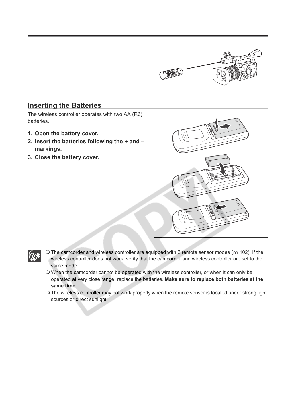
Using the Wireless Controller
When you press the buttons on the wireless
controller, point it at the camcorder’s remote
sensor.
Inserting the Batteries
The wireless controller operates with two AA (R6)
batteries.
1. Open the battery cover.
2. Insert the batteries following the + and –
markings.
3. Close the battery cover.
20
The camcorder and wireless controller are equipped with 2 remote sensor modes ( 102). If the
wireless controller does not work, verify that the camcorder and wireless controller are set to the
same mode.
When the camcorder cannot be operated with the wireless controller, or when it can only be
operated at very close range, replace the batteries. Make sure to replace both batteries at the
same time.
The wireless controller may not work properly when the remote sensor is located under strong light
sources or direct sunlight.
Page 21

Loading/Removing a Cassette
Use only videocassettes marked with the logo. For recording in HDV we recommend you use
videocassettes compatible with the HDV standard.
1. Slide the OPEN/EJECT switch to open
the cassette compartment cover.
The cassette compartment opens automatically.
2. Load/remove the cassette.
• Insert the cassette straight, fully into the
compartment with the window facing out.
• Remove the cassette by pulling it straight out.
E
Preparations
3. Close the cassette compartment by
pressing on the mark on the cover.
The cassette compartment will retract automatically.
4. Close the cassette compartment cover.
Do not interfere with the cassette compartment while it is opening or closing automatically.
Be careful not to get your fingers caught in the cassette compartment.
If the camcorder is connected to a power source, cassettes can be loaded/removed even if the
dial is set to OFF.
21
Page 22
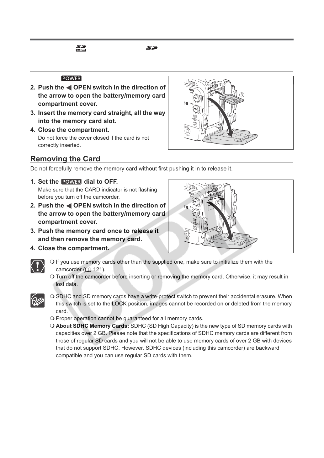
Inserting/Removing a Memory Card
You can use only SDHC memory cards, SD memory cards or MultiMedia Cards (MMC) with
this camcorder.
Inserting the Card
1. Set the dial to OFF.
2. Push the OPEN switch in the direction of
the arrow to open the battery/memory card
compartment cover.
3. Insert the memory card straight, all the way
into the memory card slot.
4. Close the compartment.
Do not force the cover closed if the card is not
correctly inserted.
Removing the Card
Do not forcefully remove the memory card without first pushing it in to release it.
1. Set the dial to OFF.
Make sure that the CARD indicator is not flashing
before you turn off the camcorder.
2. Push the OPEN switch in the direction of
the arrow to open the battery/memory card
compartment cover.
3. Push the memory card once to release it
and then remove the memory card.
4. Close the compartment.
22
If you use memory cards other than the supplied one, make sure to initialize them with the
camcorder ( 121).
Turn off the camcorder before inserting or removing the memory card. Otherwise, it may result in
lost data.
SDHC and SD memory cards have a write-protect switch to prevent their accidental erasure. When
this switch is set to the LOCK position, images cannot be recorded on or deleted from the memory
card.
Proper operation cannot be guaranteed for all memory cards.
About SDHC Memory Cards: SDHC (SD High Capacity) is the new type of SD memory cards with
capacities over 2 GB. Please note that the specifications of SDHC memory cards are different from
those of regular SD cards and you will not be able to use memory cards of over 2 GB with devices
that do not support SDHC. However, SDHC devices (including this camcorder) are backward
compatible and you can use regular SD cards with them.
Page 23

Changing Settings with the MENU Button
Many of the camcorder’s functions can be changed from the on-screen menu.
SELECT/SET dial
MENU button
Selecting Menus and Settings
1. Press the MENU button to open the menu.
2. Turn the SELECT/SET dial to select a submenu and press the dial.
3. Turn the SELECT/SET dial to select a menu item and press the dial.
4. Turn the SELECT/SET dial to select a setting option and press the dial.
5. Press the MENU button to close the menu.
E
Preparations
The , and displays at the bottom of the screen will give you additional indications
about what buttons to operate during each menu setting.
You may find it more convenient to use the wireless controller to operate the menu. Press the
MENU button on the wireless controller to open or close the menu. Use the menu selection buttons
of the wireless controller instead of the SELECT/SET dial, and press the SET button on the
wireless controller to save the settings or make a selection.
Unavailable items will appear grayed out.
Pressing the MENU button at any time closes the menu.
23
Page 24
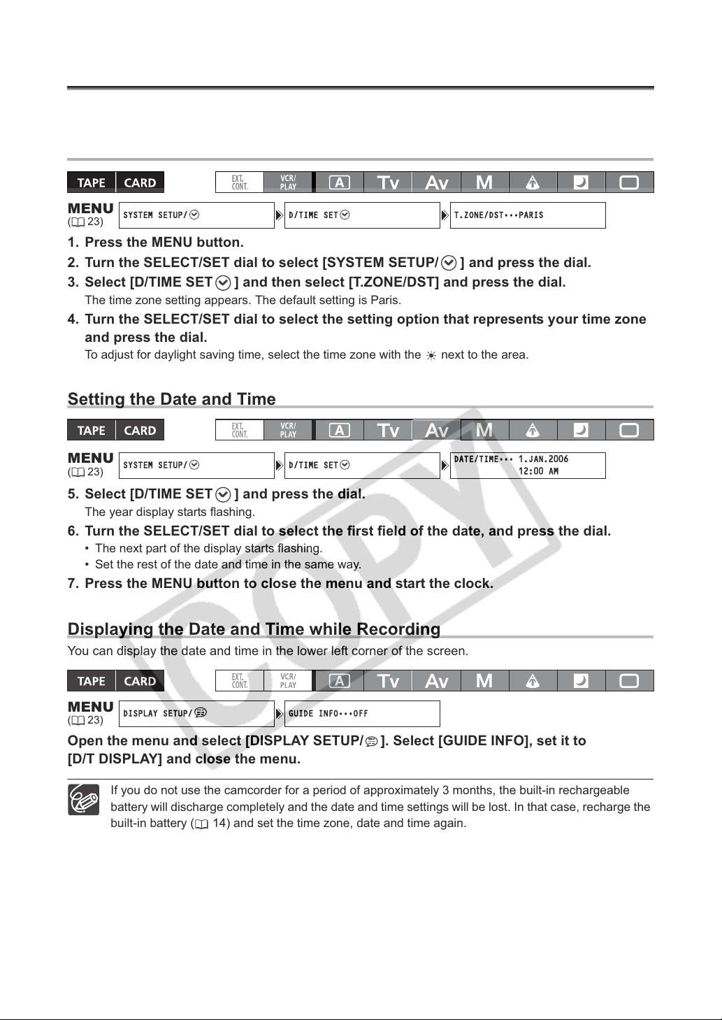
Setting the Time Zone, Date and Time
SYSTEM SETUP/ D/TIME SET T.ZONE/DST•••PARIS
SYSTEM SETUP/ D/TIME SET
DATE/TIME••• 1.JAN.2006
12:00 AM
DISPLAY SETUP/ GUIDE INFO•••OFF
Set the time zone, date and time when you first start using your camcorder, or if the built-in rechargeable
battery has completely discharged.
Setting the Time Zone/Daylight Saving Time
MENU
(23)
1. Press the MENU button.
2. Turn the SELECT/SET dial to select [SYSTEM SETUP/ ] and press the dial.
3. Select [D/TIME SET ] and then select [T.ZONE/DST] and press the dial.
The time zone setting appears. The default setting is Paris.
4. Turn the SELECT/SET dial to select the setting option that represents your time zone
and press the dial.
To adjust for daylight saving time, select the time zone with the next to the area.
Setting the Date and Time
MENU
(23)
5. Select [D/TIME SET ] and press the dial.
The year display starts flashing.
6. Turn the SELECT/SET dial to select the first field of the date, and press the dial.
• The next part of the display starts flashing.
• Set the rest of the date and time in the same way.
7. Press the MENU button to close the menu and start the clock.
Displaying the Date and Time while Recording
You can display the date and time in the lower left corner of the screen.
MENU
(23)
Open the menu and select [DISPLAY SETUP/ ]. Select [GUIDE INFO], set it to
[D/T DISPLAY] and close the menu.
24
If you do not use the camcorder for a period of approximately 3 months, the built-in rechargeable
battery will discharge completely and the date and time settings will be lost. In that case, recharge the
built-in battery ( 14) and set the time zone, date and time again.
Page 25
Recording
Recording
Before You Begin Recording
Make a test recording first to check if the camcorder operates correctly. If necessary, clean the video heads
(144).
The default recording standard is HDV. About the audio recording, refer to the relevant chapter ( 43).
Recording
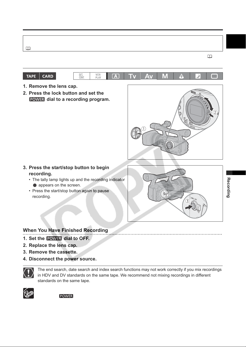
1. Remove the lens cap.
2. Press the lock button and set the
dial to a recording program.
3. Press the start/stop button to begin
recording.
• The tally lamp lights up and the recording indicator
appears on the screen.
• Press the start/stop button again to pause
recording.
E
Recording
When You Have Finished Recording
1. Set the dial to OFF.
2. Replace the lens cap.
3. Remove the cassette.
4. Disconnect the power source.
The end search, date search and index search functions may not work correctly if you mix recordings
in HDV and DV standards on the same tape. We recommend not mixing recordings in different
standards on the same tape.
After inserting a cassette, wait until the tape counter stops completely before you start recording.
Turn the dial to OFF if you do not intend to use the camcorder for a long time.
If you do not remove the cassette, you can record the next scene without any noise or blank
sections between the recordings even if you turn the camcorder off.
25
Page 26

Low-angle Recording
The carrying handle is equipped with a duplicate set
of recording and zoom controls, ideal for low-angle
recording. Slide the LOCK switch in the direction of
the arrow to prevent the accidental operation of
these controls.
Zoom lever
LOCK
switch
Start/stop
button
Power Saving Mechanisms
STANDBY Lever
Switch the STANDBY lever to the LOCK position to temporarily pause the recording and turn off all displays.
In contrast to turning the dial to OFF, in the standby mode the camcorder retains the exposure lock
settings.
Power Save Function
In order to protect the tape and video heads, the camcorder will enter the power save mode (VCR STOP) after
4 minutes 30 seconds in record pause mode. If left 30 more seconds without any operation, the camcorder
will automatically shut off. With the customized functions ( 79) you can also deactivate the power save
function if you wish to make adjustments without worrying about losing your settings as a result of the
automatic shut-off.
Once the camcorder entered the power save mode, press the start/stop button to start recording or press one
of the custom keys ( 66) to which the [VCR STOP] function was assigned to return to record pause mode.
If the camcorder automatically shut off (after 5 minutes), turn the to OFF and then back to one of the
recording programs.
VCR Stop Function
You can assign the [VCR STOP] function to either one of the two custom keys ( 66). In VCR stop mode the
camcorder is only partially turned off: The camera section is powered normally while the recorder section is
shut off. When you press the assigned custom key, you can make adjustments to the camera section as long
as necessary without worrying about the power save function’s 5-minute timer. To return to record pause
mode, press the custom key to which the [VCR STOP] function was assigned.
26
Page 27
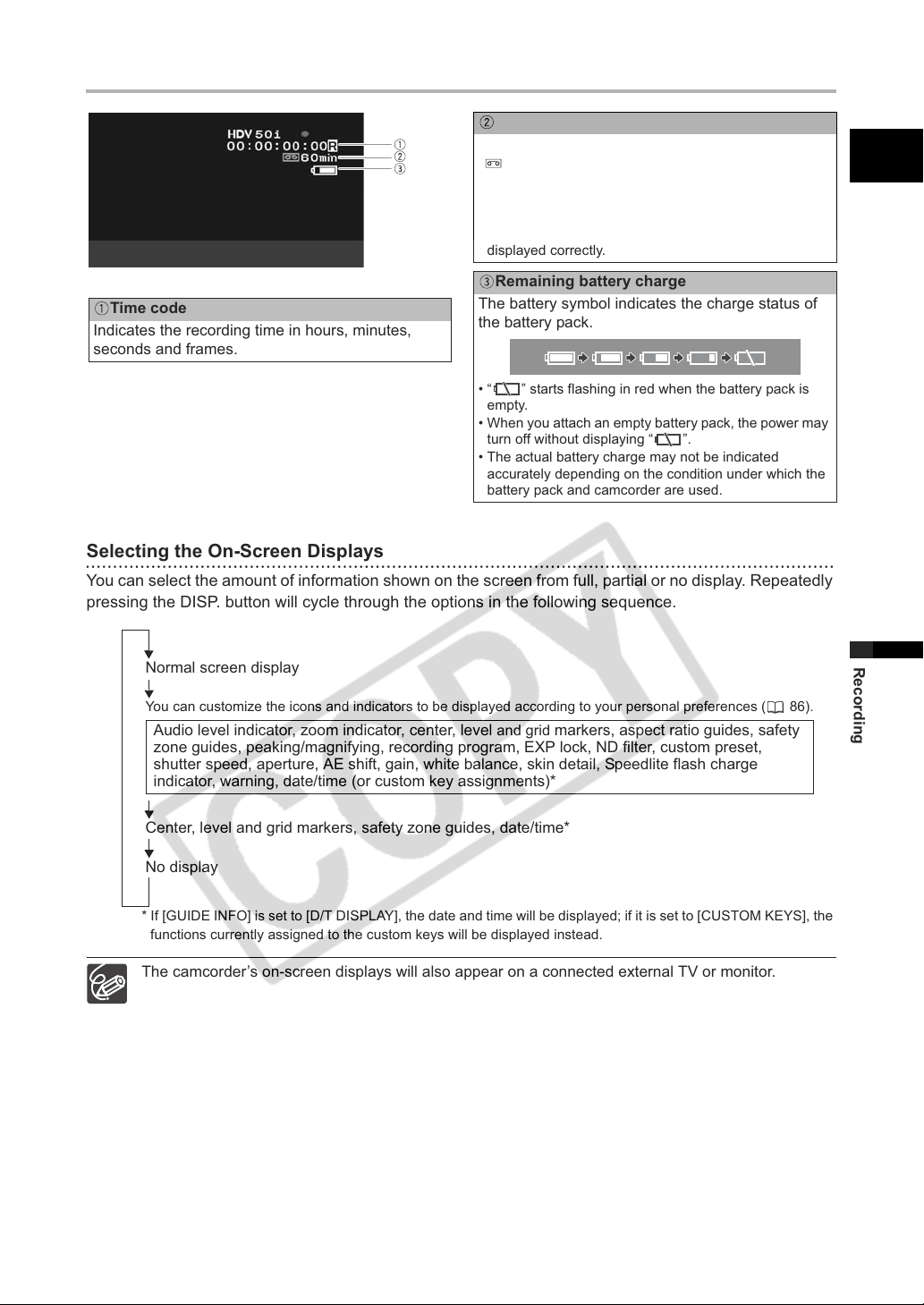
Screen Displays while Recording
Remaining tape
Indicates the remaining time of the tape in minutes.
“ END” will appear when the tape reaches the
end.
• When the time left is less than 15 seconds, the
remaining tape time may not appear.
• Depending on the tape, the indication may not be
displayed correctly.
Remaining battery charge
Time code
Indicates the recording time in hours, minutes,
seconds and frames.
Selecting the On-Screen Displays
You can select the amount of information shown on the screen from full, partial or no display. Repeatedly
pressing the DISP. button will cycle through the options in the following sequence.
The battery symbol indicates the charge status of
the battery pack.
• “ ” starts flashing in red when the battery pack is
empty.
• When you attach an empty battery pack, the power may
turn off without displaying “ ”.
• The actual battery charge may not be indicated
accurately depending on the condition under which the
battery pack and camcorder are used.
E
Normal screen display
You can customize the icons and indicators to be displayed according to your personal preferences ( 86).
Audio level indicator, zoom indicator, center, level and grid markers, aspect ratio guides, safety
zone guides, peaking/magnifying, recording program, EXP lock, ND filter, custom preset,
shutter speed, aperture, AE shift, gain, white balance, skin detail, Speedlite flash charge
indicator, warning, date/time (or custom key assignments)*
Center, level and grid markers, safety zone guides, date/time*
No display
* If [GUIDE INFO] is set to [D/T DISPLAY], the date and time will be displayed; if it is set to [CUSTOM KEYS], the
functions currently assigned to the custom keys will be displayed instead.
The camcorder’s on-screen displays will also appear on a connected external TV or monitor.
Recording
27
Page 28
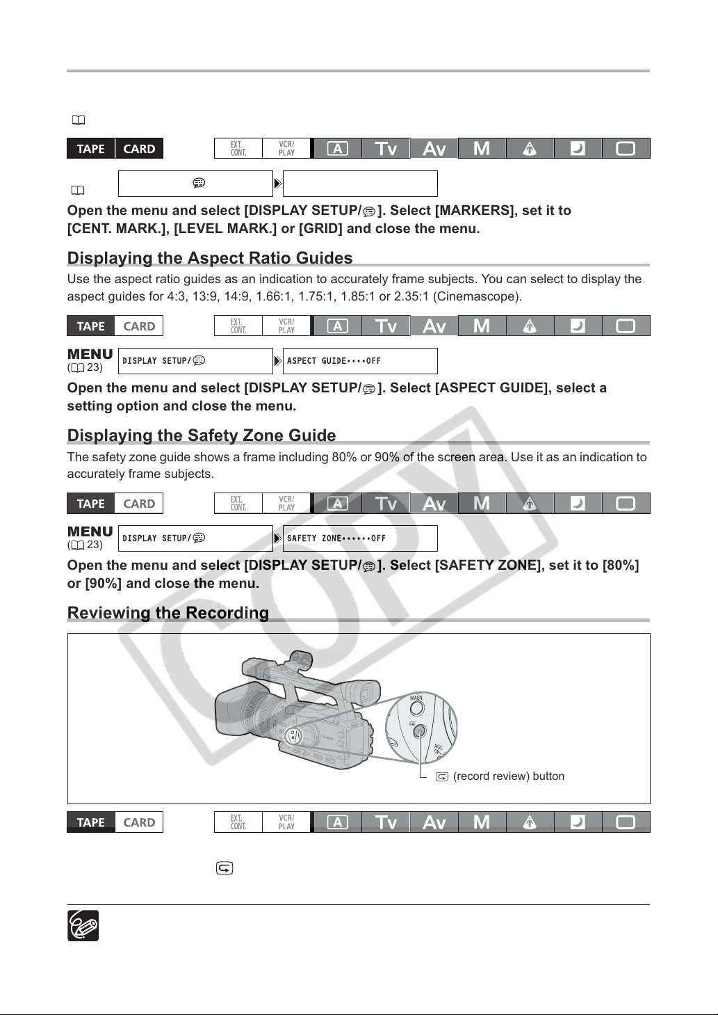
Displaying the Markers
DISPLAY SETUP/ MARKERS•••OFF
DISPLAY SETUP/ ASPECT GUIDE••••OFF
DISPLAY SETUP/ SAFETY ZONE••••••OFF
You can display the on-screen markers to help you accurately frame your subject. Select from a center
marker, a horizontal level marker or a grid. You can also adjust the intensity of the markers display
(
84).
MENU
(23)
Open the menu and select [DISPLAY SETUP/ ]. Select [MARKERS], set it to
[CENT. MARK.], [LEVEL MARK.] or [GRID] and close the menu.
Displaying the Aspect Ratio Guides
Use the aspect ratio guides as an indication to accurately frame subjects. You can select to display the
aspect guides for 4:3, 13:9, 14:9, 1.66:1, 1.75:1, 1.85:1 or 2.35:1 (Cinemascope).
MENU
(23)
Open the menu and select [DISPLAY SETUP/ ]. Select [ASPECT GUIDE], select a
setting option and close the menu.
Displaying the Safety Zone Guide
The safety zone guide shows a frame including 80% or 90% of the screen area. Use it as an indication to
accurately frame subjects.
MENU
(23)
Open the menu and select [DISPLAY SETUP/ ]. Select [SAFETY ZONE], set it to [80%]
or [90%] and close the menu.
Reviewing the Recording
(record review) button
In record pause mode, this function allows you to review the last few seconds of your recording.
Press and release the (record review) button.
The camcorder rewinds the tape, plays back the last few seconds, and returns to record pause mode.
If the current video signal standard is different from the signal standard in which the tape was
recorded, the recording will not be played back correctly.
28
Page 29

Selecting the Signal Standard and Aspect
Ratio
You can select the signal standard of your recording (high definition or standard definition) and, for
standard definition recordings, also the aspect ratio of the recording. Since the displays on the
camcorder have an aspect ratio of 16:9, when you select [SD4:3] the picture will appear in the center of
the screen with black sidebars.
Open the menu and select [SIGNAL SETUP]. Select [SIGNAL STD], select a setting
option and select [YES] to confirm the selection and close the menu.
• [HD]: To record on the tape in HDV standard or to use the camcorder as a high-definition (HD) camera.
• [SD16:9], [SD4:3]: To record on the tape in DV standard or to use the camcorder as a standard-definition
(SD) camera. Select the aspect ratio as desired.
To play back recordings made with a 16:9 aspect ratio change the settings of the TV as necessary
(refer to the instruction manual of the connected TV). To play back widescreen recordings on a TV set
with 4:3 aspect ratio, change the [LETTERBOX] setting accordingly ( 95).
E
Recording
29
Page 30
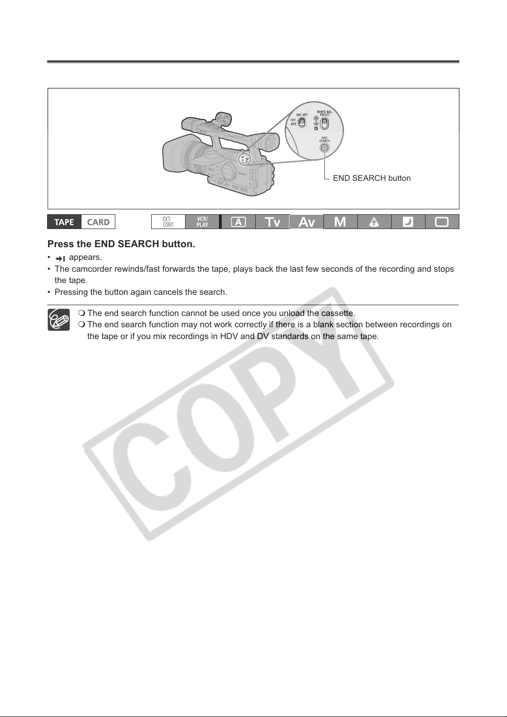
Locating the End of the Last Scene
You can use this function to locate the end of the last recorded scene.
END SEARCH button
Press the END SEARCH button.
• appears.
• The camcorder rewinds/fast forwards the tape, plays back the last few seconds of the recording and stops
the tape.
• Pressing the button again cancels the search.
The end search function cannot be used once you unload the cassette.
The end search function may not work correctly if there is a blank section between recordings on
the tape or if you mix recordings in HDV and DV standards on the same tape.
30
Page 31
Zooming
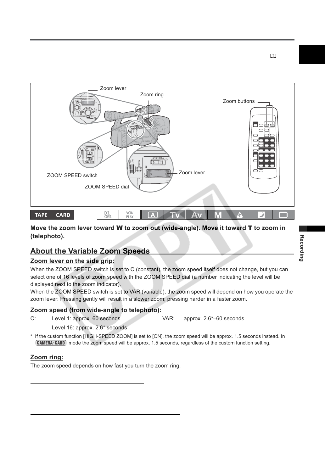
You can operate the zoom from either the side grip or the carrying handle. You can also use the zoom
ring on the lens or the zoom buttons on the wireless controller. With the customized functions ( 79)
you can change the direction of the adjustment when you turn the zoom ring, turn the high-speed zoom
on/off or change the zoom indicator to a graphic bar or a numeric value display.
E
Zoom lever
ZOOM SPEED switch
ZOOM SPEED dial
Zoom ring
Zoom buttons
Zoom lever
Move the zoom lever toward W to zoom out (wide-angle). Move it toward T to zoom in
(telephoto).
About the Variable Zoom Speeds
Zoom lever on the side grip:
When the ZOOM SPEED switch is set to C (constant), the zoom speed itself does not change, but you can
select one of 16 levels of zoom speed with the ZOOM SPEED dial (a number indicating the level will be
displayed next to the zoom indicator).
When the ZOOM SPEED switch is set to VAR (variable), the zoom speed will depend on how you operate the
zoom lever: Pressing gently will result in a slower zoom; pressing harder in a faster zoom.
Recording
Zoom speed (from wide-angle to telephoto):
C: Level 1: approx. 60 seconds VAR: approx. 2.6*–60 seconds
Level 16: approx. 2.6* seconds
* If the custom function [HIGH-SPEED ZOOM] is set to [ON], the zoom speed will be approx. 1.5 seconds instead. In
mode the zoom speed will be approx. 1.5 seconds, regardless of the custom function setting.
Zoom ring:
The zoom speed depends on how fast you turn the zoom ring.
Zoom buttons on the carrying handle:
The zoom speed itself does not change, but it can be set to one of 16 levels with the ZOOM SPEED dial.
This is the same zoom speed setting as when the ZOOM SPEED switch is set to C.
Zoom buttons on the supplied wireless controller:
The zoom speed is constant and cannot be adjusted.
31
Page 32
Zoom Preset
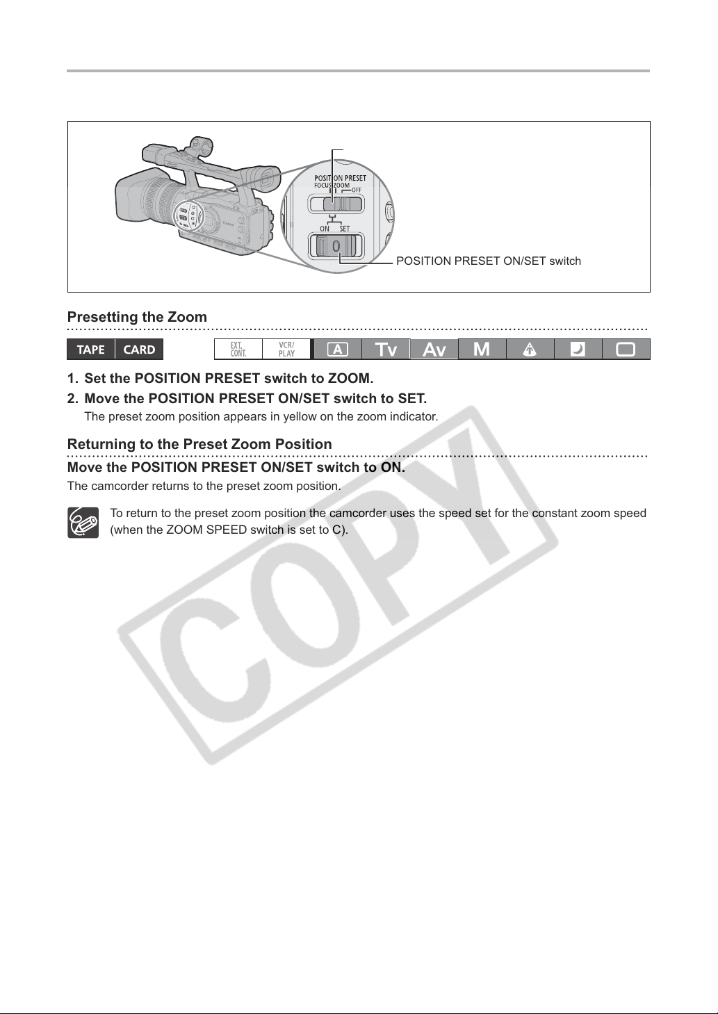
This function enables any given zoom setting to be memorized and to return to that zoom setting
instantly.
POSITION PRESET switch
POSITION PRESET ON/SET switch
Presetting the Zoom
1. Set the POSITION PRESET switch to ZOOM.
2. Move the POSITION PRESET ON/SET switch to SET.
The preset zoom position appears in yellow on the zoom indicator.
Returning to the Preset Zoom Position
Move the POSITION PRESET ON/SET switch to ON.
The camcorder returns to the preset zoom position.
To return to the preset zoom position the camcorder uses the speed set for the constant zoom speed
(when the ZOOM SPEED switch is set to C).
32
Page 33
Adjusting the Focus
CAMERA SETUP AF MODE ••• INSTANT AF
The camcorder can be set to Autofocus or Manual Focus.
Autofocus
The autofocus can be set to Normal AF or Instant AF*. The camcorder has also a Push-AF function to
allow for a temporary autofocus while focusing manually. When you operate the PUSH AF button, the
Instant AF is activated, regardless of the current setting of the AF mode.
Manual Focus
With the customized functions (
focus ring and its response sensitivity ([NORMAL] or [SLOW]). To make it easier to focus manually, you can
also make use of the Peaking and Magnifying display functions ( 35).
* The Instant AF function can also be used combined with the Push-AF function so you can obtain a very fast
initial automatic focus even while focusing manually.
79) you can change the direction of the adjustment when you turn the
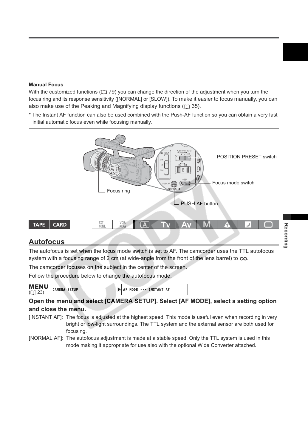
POSITION PRESET switch
Focus mode switch
Focus ring
PUSH AF button
E
Autofocus
The autofocus is set when the focus mode switch is set to AF. The camcorder uses the TTL autofocus
system with a focusing range of 2 cm (at wide-angle from the front of the lens barrel) to .
The camcorder focuses on the subject in the center of the screen.
Follow the procedure below to change the autofocus mode.
MENU
(23)
Open the menu and select [CAMERA SETUP]. Select [AF MODE], select a setting option
and close the menu.
[INSTANT AF]: The focus is adjusted at the highest speed. This mode is useful even when recording in very
[NORMAL AF]: The autofocus adjustment is made at a stable speed. Only the TTL system is used in this
bright or low-light surroundings. The TTL system and the external sensor are both used for
focusing.
mode making it appropriate for use also with the optional Wide Converter attached.
Recording
33
Page 34
Temporary Focus Override
Even while in autofocus mode, turn the focus ring to temporarily focus manually.
The camcorder will return to autofocus as soon as you release the focus ring.
Temporary Instant AF
During manual focus or Normal AF, press the PUSH AF button and hold it pressed down.
The autofocus (Instant AF) is activated as long as you hold the PUSH AF button pressed down.
When recording under bright conditions, the camcorder sets a small aperture value, and the picture
may appear blurred. Turn the built-in ND filter on/off according to the screen display ( 37).
When you attach the optional Wide Converter to the camcorder, set the camcorder to a recording
mode other than Easy Recording and set the autofocus mode to Normal AF. Also, avoid using
the Push AF function.
In 25F mode, autofocus takes longer than in the 50i mode.
When recording under dark conditions, the focusing range narrows and the picture may appear
blurred.
Autofocus may not work well on the following subjects. In that case, focus manually.
- Reflective surfaces
- Subjects with low contrast or without vertical lines
- Fast moving subjects
- Through dirty or wet windows
- Night scenes
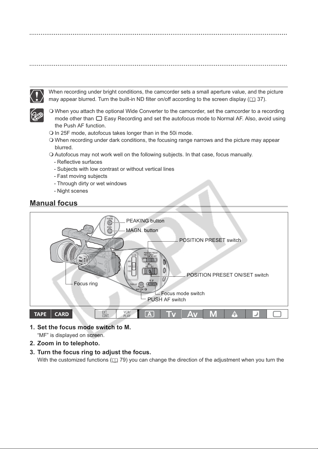
Manual focus
PEAKING button
MAGN. button
POSITION PRESET switch
POSITION PRESET ON/SET switch
Focus ring
Focus mode switch
PUSH AF switch
1. Set the focus mode switch to M.
“MF” is displayed on screen.
2. Zoom in to telephoto.
3. Turn the focus ring to adjust the focus.
With the customized functions ( 79) you can change the direction of the adjustment when you turn the
focus ring and its response sensitivity ([NORMAL] or [SLOW]).
4. Operate the zoom to reframe the subject.
If you focus manually and then leave the camcorder with the power turned on, you may lose the focus on
your subject. This possible slight shift in focus is a result of the internal temperature rising in the camcorder
and lens. Check the focus before resuming shooting.
34
Page 35
The manual focus cannot be selected in the Easy Recording mode. Even if you set the focus
mode switch to M, the autofocus (Instant AF) will still be activated.
The focal distance to the subject will be displayed for approx. 3 seconds when you switch from
autofocus to manual focus or when you operate the focus ring in the manual focus mode. It will also
be displayed with the focus preset. With the customized functions ( 79) you can change the units
for the distance display (meter or feet) and with the custom display ( 86) you can select when to
display this information (always, never, or only upon the operation of the focus ring).
Use the distance display as an estimate.
: Infinity focus -: Over infinity focus
Using the Focus Assist Functions (Peaking and Magnifying)
In order to make manual focusing easier, you can use two assist functions: Peaking emphasizes the
outlines of the subject creating a clearer contrast, and Magnifying enlarges the image on the screen. You
can also combine both for a greater effect. With the customized functions ( 79) you can set the display
to change automatically to black & white while using the focus assist functions.
Peaking
While recording or in record pause, press the PEAKING button.
• The outlines of the subject will be emphasized.
• Press the button again to cancel the function.
Magnifying
In record pause, press the MAGN. button.
• The central part of the screen will be magnified approximately 2x.
• Press the button again to cancel the function.
The Peaking and Magnifying functions will not affect your recordings. However, the magnified
picture will be output as is to the HD/SD SDI terminal ( only) and the HDV/DV terminal.
The Magnifying function will be canceled as you start recording.
You can use the custom keys ( 66) to prevent the accidental operation of the MAGN. button.
With the customized functions ( 79) you can also change the operation of the MAGN. button
(normal or long press).
E
Recording
Focus Preset
This function enables a focus setting to be memorized and to return to that focus setting instantly. You
can also select the speed at which the camcorder returns to the preset focus setting.
Presetting the Focus
1. Set the focus mode switch to M.
“MF” appears.
2. Set the POSITION PRESET switch to FOCUS.
The focus preset speed currently selected appears.
3. Adjust the focus with the focus ring.
4. Move the POSITION PRESET ON/SET switch to SET.
“MF” and the focus preset speed display turn yellow.
35
Page 36
Setting the Focus Preset Speed
CAMERA SETUP F SPEED PSET•HIGH
MENU
(23)
Open the menu and select [CAMERA SETUP]. Select [F SPEED PSET], select a setting
option and close the menu.
The selected speed appears next to “MF”.
Returning to the Preset Focus Setting
Move the POSITION PRESET ON/SET switch to ON.
The camcorder returns to the preset focus setting.
36
Page 37
Using the ND Filter
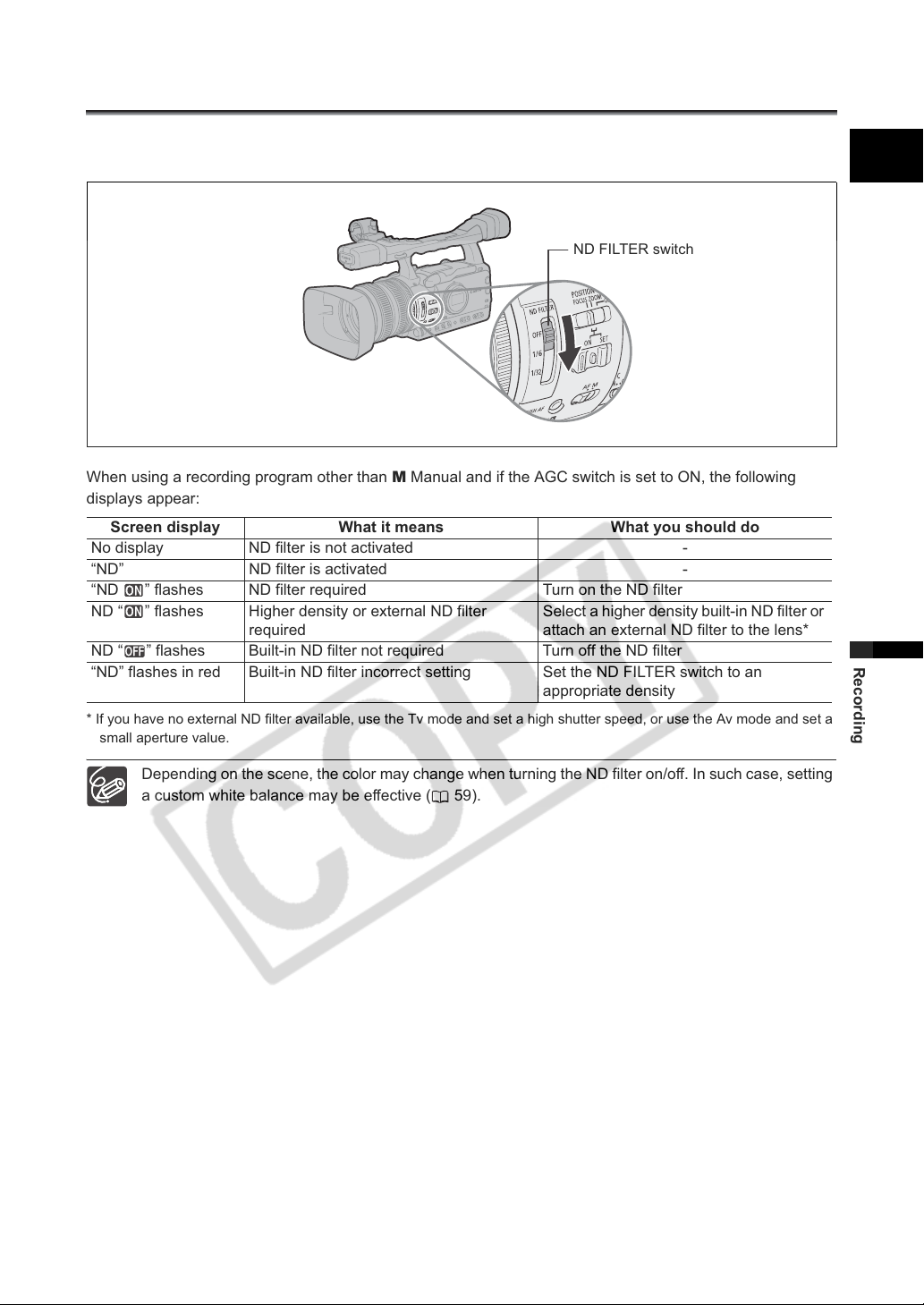
When recording in bright surroundings, the camcorder will set a small aperture value and the picture
may appear blurred. Turn the ND filter on/off according to the screen display.
ND FILTER switch
When using a recording program other than M Manual and if the AGC switch is set to ON, the following
displays appear:
Screen display What it means What you should do
No display ND filter is not activated -
“ND” ND filter is activated -
“ND ” flashes ND filter required Turn on the ND filter
ND “ ” flashes Higher density or external ND filter
required
ND “ ” flashes Built-in ND filter not required Turn off the ND filter
“ND” flashes in red Built-in ND filter incorrect setting Set the ND FILTER switch to an
* If you have no external ND filter available, use the Tv mode and set a high shutter speed, or use the Av mode and set a
small aperture value.
Select a higher density built-in ND filter or
attach an external ND filter to the lens*
appropriate density
E
Recording
Depending on the scene, the color may change when turning the ND filter on/off. In such case, setting
a custom white balance may be effective ( 59).
37
Page 38
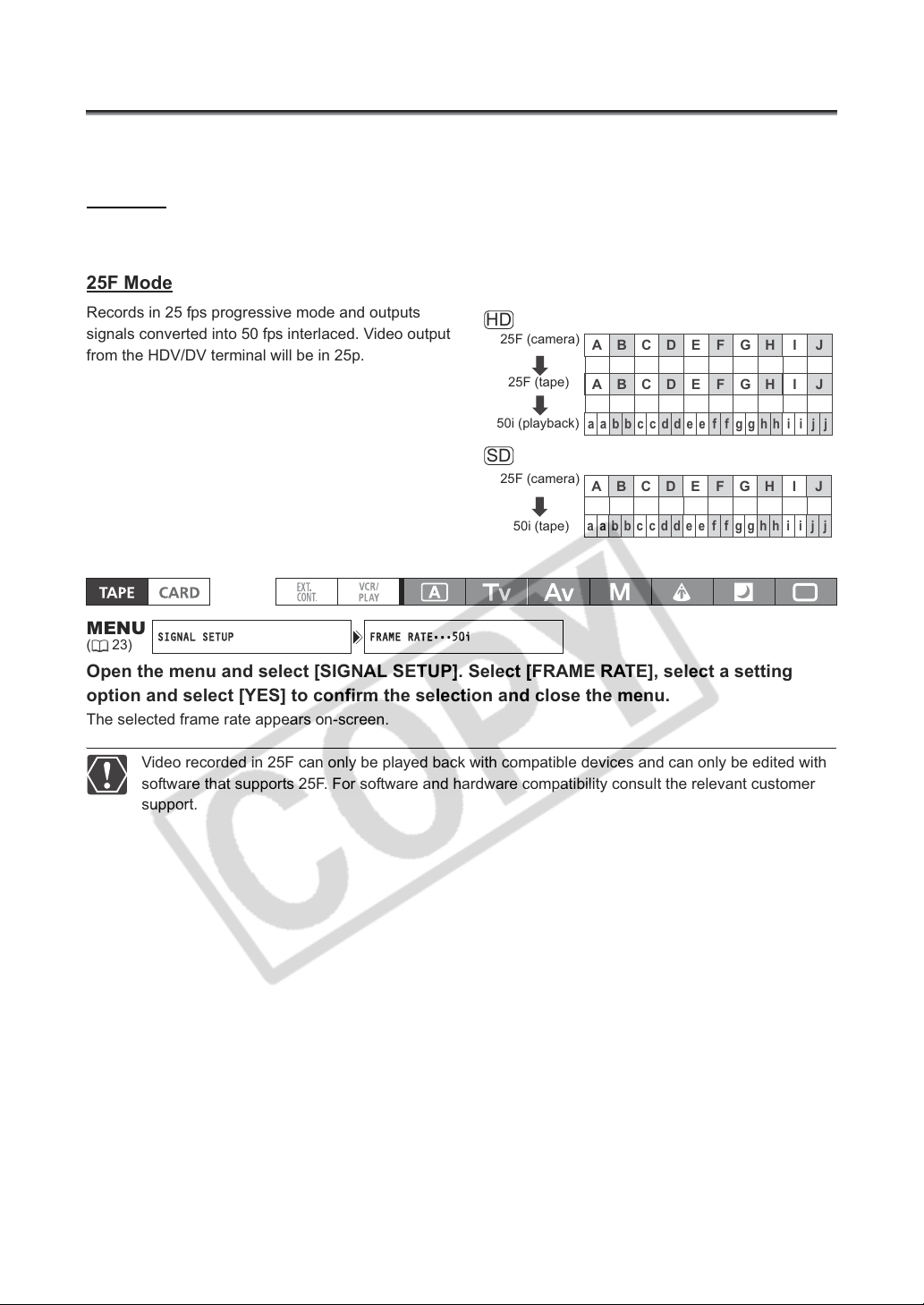
Selecting the Frame Rate
SIGNAL SETUP FRAME RATE•••50i
You can select from the standard 50i and 25F frame rates regardless of the recording mode.
50i Mode
Records in 50 fps interlaced mode, the same as standard-definition TV signals.
25F Mode
Records in 25 fps progressive mode and outputs
signals converted into 50 fps interlaced. Video output
from the HDV/DV terminal will be in 25p.
HD
25F (camera)
25F (tape)
A B C D E F G H IJ
A B C D E F G H IJ
50i (playback)
aabbccddeeffgghh iijj
SD
MENU
(23)
25F (camera)
50i (tape)
A B C D E F G H IJ
aabbccddeeffgghh iijj
Open the menu and select [SIGNAL SETUP]. Select [FRAME RATE], select a setting
option and select [YES] to confirm the selection and close the menu.
The selected frame rate appears on-screen.
Video recorded in 25F can only be played back with compatible devices and can only be edited with
software that supports 25F. For software and hardware compatibility consult the relevant customer
support.
38
Page 39
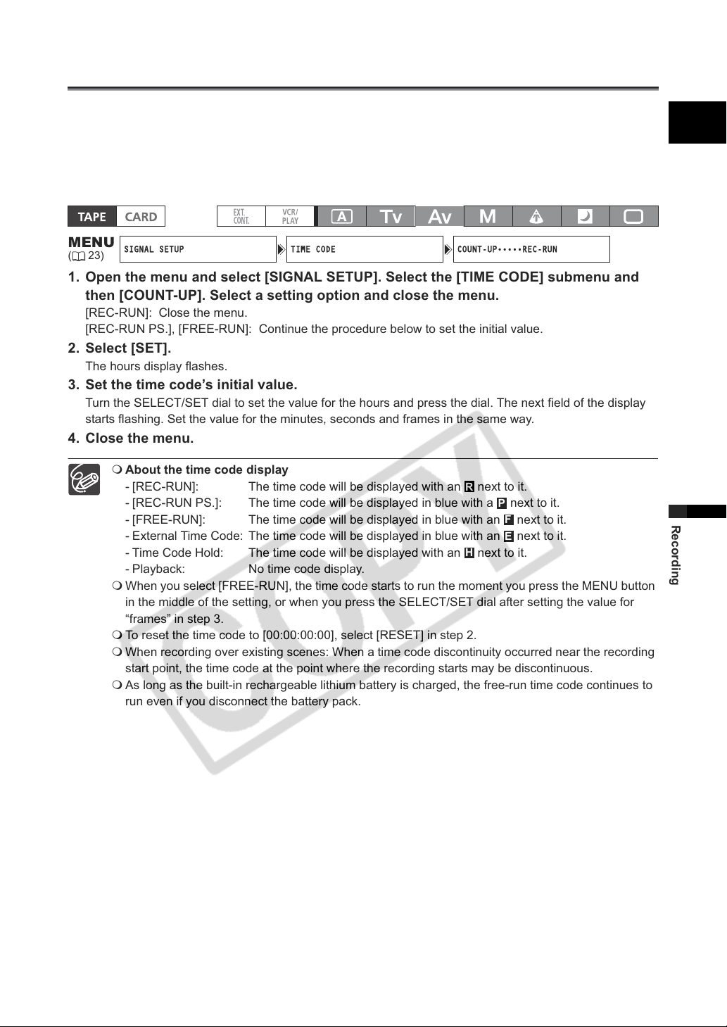
Setting the Time Code
SIGNAL SETUP TIME CODE COUNT-UP•••••REC-RUN
You can select the running mode of the camcorder’s time code. You can enter the initial value for the
[FREE-RUN] and the [REC-RUN PS.] settings.
[REC-RUN]: The time code runs only when recording.
[REC-RUN PS.]: The time code runs only when recording starting from a preset value.
[FREE-RUN]: The time code runs regardless of the operation of the camcorder.
E
MENU
(23)
1. Open the menu and select [SIGNAL SETUP]. Select the [TIME CODE] submenu and
then [COUNT-UP]. Select a setting option and close the menu.
[REC-RUN]: Close the menu.
[REC-RUN PS.], [FREE-RUN]: Continue the procedure below to set the initial value.
2. Select [SET].
The hours display flashes.
3. Set the time code’s initial value.
Turn the SELECT/SET dial to set the value for the hours and press the dial. The next field of the display
starts flashing. Set the value for the minutes, seconds and frames in the same way.
4. Close the menu.
About the time code display
- [REC-RUN]: The time code will be displayed with an next to it.
- [REC-RUN PS.]: The time code will be displayed in blue with a next to it.
- [FREE-RUN]: The time code will be displayed in blue with an next to it.
- External Time Code: The time code will be displayed in blue with an next to it.
- Time Code Hold: The time code will be displayed with an next to it.
- Playback: No time code display.
When you select [FREE-RUN], the time code starts to run the moment you press the MENU button
in the middle of the setting, or when you press the SELECT/SET dial after setting the value for
“frames” in step 3.
To reset the time code to [00:00:00:00], select [RESET] in step 2.
When recording over existing scenes: When a time code discontinuity occurred near the recording
start point, the time code at the point where the recording starts may be discontinuous.
As long as the built-in rechargeable lithium battery is charged, the free-run time code continues to
run even if you disconnect the battery pack.
R
P
F
E
H
Recording
39
Page 40
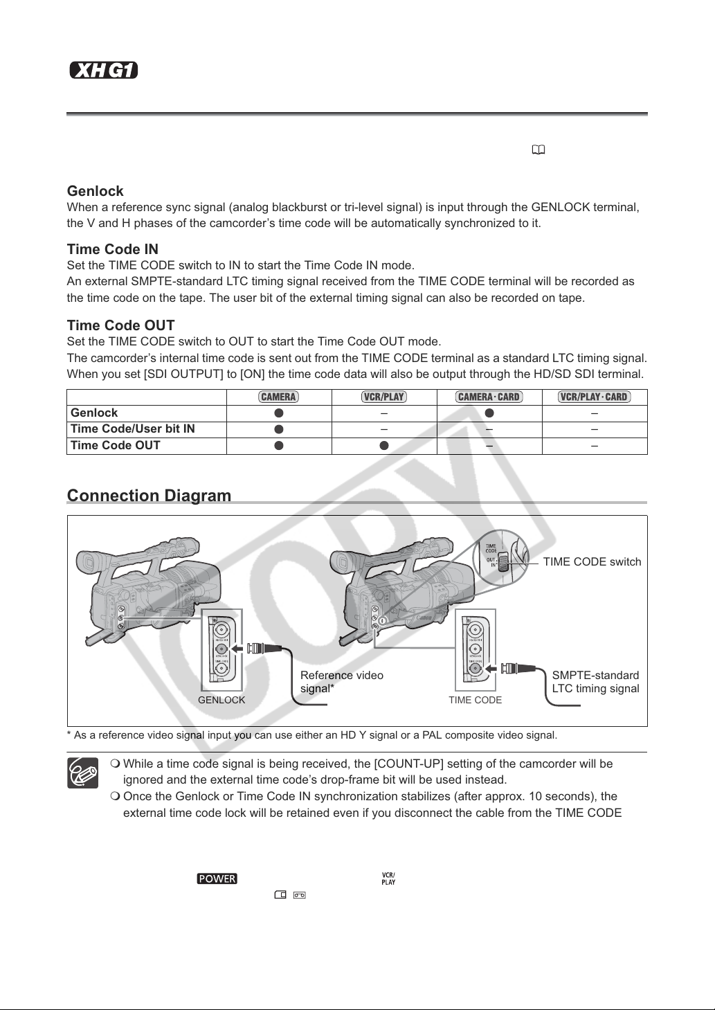
Synchronizing the Camcorder’s Time Code
You can synchronize this camcorder’s time code to an external time code generator. Also you can
include in the recording the user bit signal received from the TIME CODE terminal ( 42). The
camcorder offers the following synchronization options.
Genlock
When a reference sync signal (analog blackburst or tri-level signal) is input through the GENLOCK terminal,
the V and H phases of the camcorder’s time code will be automatically synchronized to it.
Time Code IN
Set the TIME CODE switch to IN to start the Time Code IN mode.
An external SMPTE-standard LTC timing signal received from the TIME CODE terminal will be recorded as
the time code on the tape. The user bit of the external timing signal can also be recorded on tape.
Time Code OUT
Set the TIME CODE switch to OUT to start the Time Code OUT mode.
The camcorder’s internal time code is sent out from the TIME CODE terminal as a standard LTC timing signal.
When you set [SDI OUTPUT] to [ON] the time code data will also be output through the HD/SD SDI terminal.
Genlock ––
Time Code/User bit IN –––
Time Code OUT ––
Connection Diagram
TIME CODE switch
Reference video
GENLOCK
* As a reference video signal input you can use either an HD Y signal or a PAL composite video signal.
While a time code signal is being received, the [COUNT-UP] setting of the camcorder will be
ignored and the external time code’s drop-frame bit will be used instead.
Once the Genlock or Time Code IN synchronization stabilizes (after approx. 10 seconds), the
external time code lock will be retained even if you disconnect the cable from the TIME CODE
terminal. However, if you perform one of the following while the cable is disconnected, the time
code will lag slightly; the correct time code will be restored once you reconnect the cable.
- Turn the camcorder off/on.
- Change the dial to a mode other than .
- Change the position of the / (card/tape) switch.
- Change the [SIGNAL STD] or [FRAME RATE] setting.
signal*
TIME CODE
40
SMPTE-standard
LTC timing signal
Page 41
If the external time code signal is incorrect or there is no input signal, the internal time code
(according to the [TIME CODE]/[COUNT-UP] settings) will be recorded on the tape instead.
If the external Genlock signal is incorrect or there is no input signal, the external time code being
recorded on tape may be incorrect.
When the camcorder is set to HD standard, Genlock synchronization is possible even if the
external Genlock signal is in SD standard. However, the Genlock synchronization will not be
possible if the external Genlock signal is in HD standard but the camcorder is set to SD standard.
The phase difference between the external Genlock signal and the camcorder is initially set to 0; it
can be adjusted within the range of approx. ±0.4 H (-1023 to +1023)
setting (
Genlock synchronization is not possible when the camcorder is set to HD standard and [SDI
SPEC.] is set to [SD LOCKED].
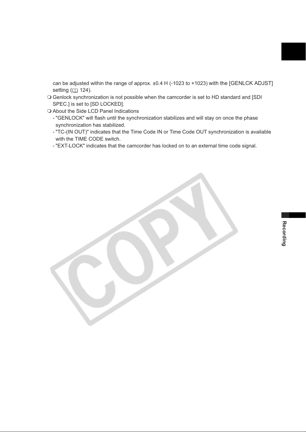
About the Side LCD Panel Indications
- "GENLOCK" will flash until the synchronization stabilizes and will stay on once the phase
synchronization has stabilized.
- "TC-(IN OUT)" indicates that the Time Code IN or Time Code OUT synchronization is available
with the TIME CODE switch.
- "EXT-LOCK" indicates that the camcorder has locked on to an external time code signal.
124).
with the [GENLCK ADJST]
E
Recording
41
Page 42
Setting the User Bit
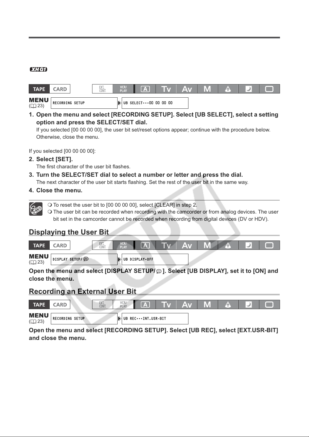
RECORDING SETUP UB SELECT•••00 00 00 00
DISPLAY SETUP/ UB DISPLAY•OFF
RECORDING SETUP UB REC•••INT.USR-BIT
The user bit display can be selected from the date or the time of recording, or an identification code
consisting of 8 characters in the hexadecimal system that is useful for labeling tapes. There are sixteen
possible characters: the numbers 0 to 9 and the letters A to F.
If a user bit is being received along with an external time code, you can also choose to record
the external user bit on tape.
MENU
(23)
1. Open the menu and select [RECORDING SETUP]. Select [UB SELECT], select a setting
option and press the SELECT/SET dial.
If you selected [00 00 00 00], the user bit set/reset options appear; continue with the procedure below.
Otherwise, close the menu.
If you selected [00 00 00 00]:
2. Select [SET].
The first character of the user bit flashes.
3. Turn the SELECT/SET dial to select a number or letter and press the dial.
The next character of the user bit starts flashing. Set the rest of the user bit in the same way.
4. Close the menu.
To reset the user bit to [00 00 00 00], select [CLEAR] in step 2.
The user bit can be recorded when recording with the camcorder or from analog devices. The user
bit set in the camcorder cannot be recorded when recording from digital devices (DV or HDV).
Displaying the User Bit
MENU
(23)
Open the menu and select [DISPLAY SETUP/ ]. Select [UB DISPLAY], set it to [ON] and
close the menu.
Recording an External User Bit
MENU
(23)
Open the menu and select [RECORDING SETUP]. Select [UB REC], select [EXT.USR-BIT]
and close the menu.
42
Page 43
Audio Recording
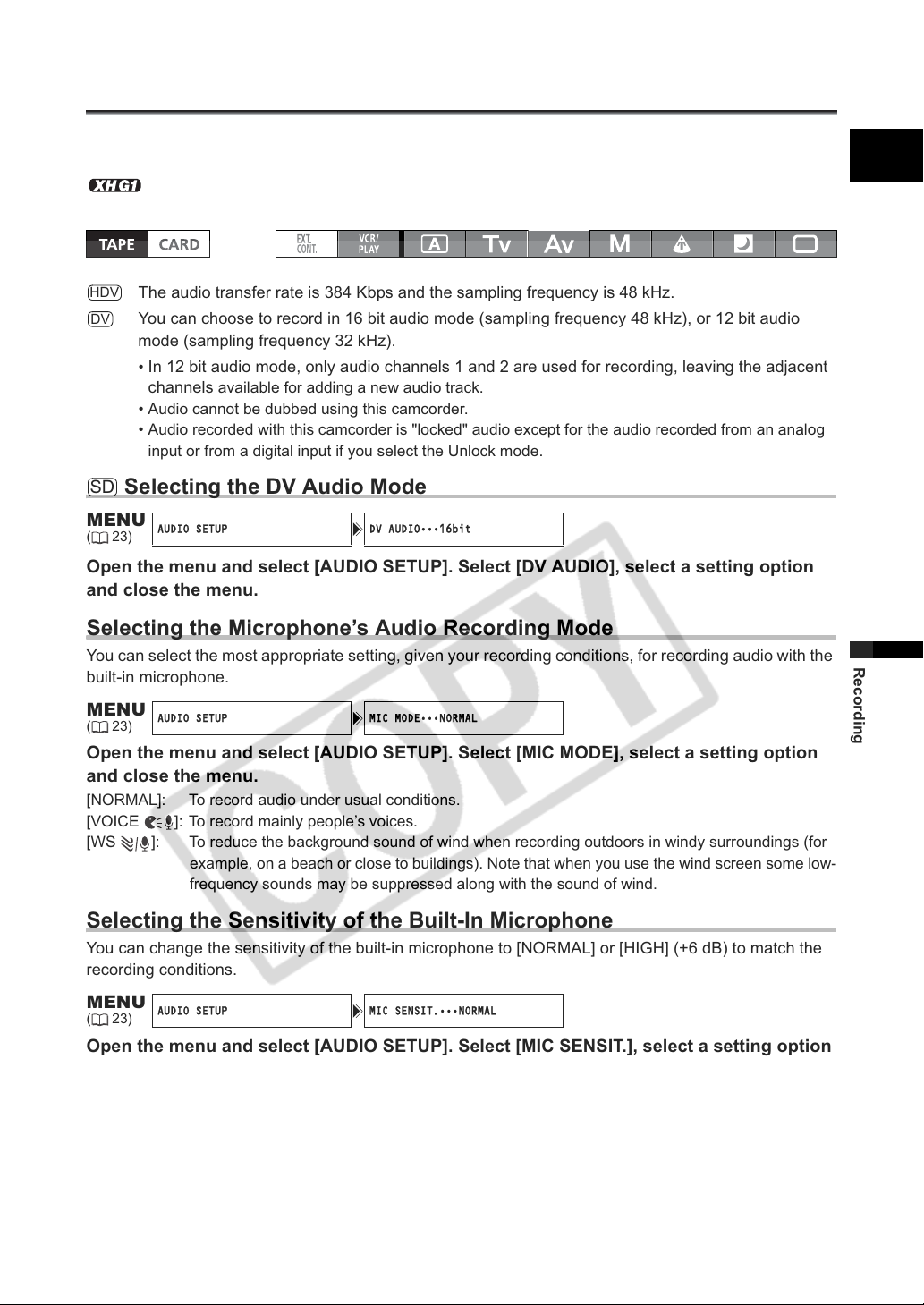
AUDIO SETUP DV AUDIO•••16bit
AUDIO SETUP MIC MODE•••NORMAL
AUDIO SETUP MIC SENSIT.•••NORMAL
You can select to record audio from the built-in microphone or from an external microphone connected
either to the MIC terminal or to the XLR terminal.
While recording, the sampling frequency of the output signal from the HD/SD SDI terminal will
be 48 kHz regardless of the audio input.
HDV
The audio transfer rate is 384 Kbps and the sampling frequency is 48 kHz.
DV
You can choose to record in 16 bit audio mode (sampling frequency 48 kHz), or 12 bit audio
mode (sampling frequency 32 kHz).
• In 12 bit audio mode, only audio channels 1 and 2 are used for recording, leaving the adjacent
channels
• Audio cannot be dubbed using this camcorder.
• Audio recorded with this camcorder is "locked" audio except for the audio recorded from an analog
input or from a digital input if you select the Unlock mode.
SD
Selecting the DV Audio Mode
available for adding a new audio track.
E
MENU
(23)
Open the menu and select [AUDIO SETUP]. Select [DV AUDIO], select a setting option
and close the menu.
Selecting the Microphone’s Audio Recording Mode
You can select the most appropriate setting, given your recording conditions, for recording audio with the
built-in microphone.
MENU
(23)
Open the menu and select [AUDIO SETUP]. Select [MIC MODE], select a setting option
and close the menu.
[NORMAL]: To record audio under usual conditions.
[VOICE ]: To record mainly people’s voices.
[WS ]: To reduce the background sound of wind when recording outdoors in windy surroundings (for
example, on a beach or close to buildings). Note that when you use the wind screen some low-
frequency sounds may be suppressed along with the sound of wind.
Selecting the Sensitivity of the Built-In Microphone
You can change the sensitivity of the built-in microphone to [NORMAL] or [HIGH] (+6 dB) to match the
recording conditions.
MENU
(23)
Open the menu and select [AUDIO SETUP]. Select [MIC SENSIT.], select a setting option
and close the menu.
[NORMAL]: To record audio under usual conditions.
[HIGH]: To record audio at a higher volume.
Recording
43
Page 44
Using an External Microphone
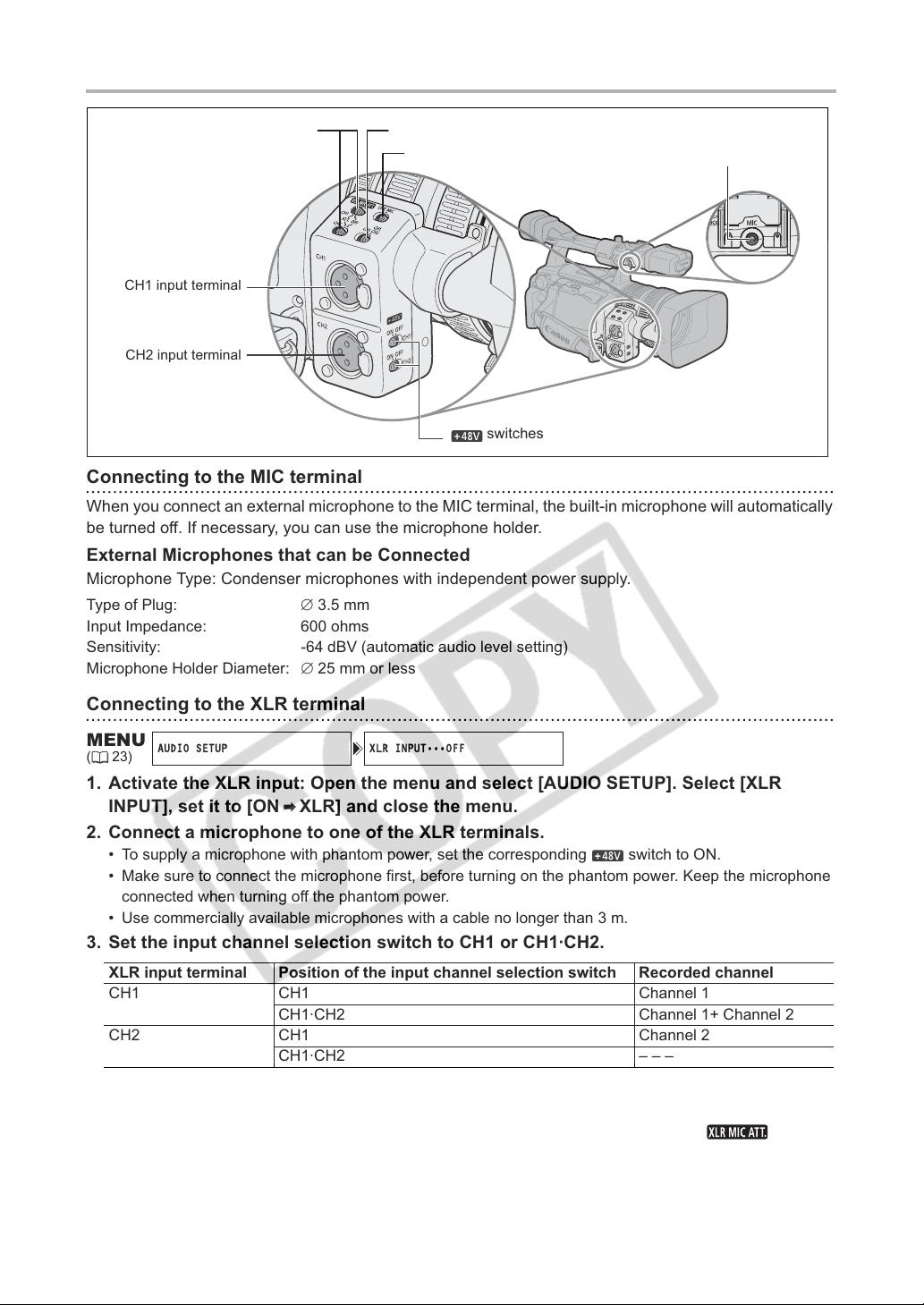
AUDIO SETUP XLR INPUT•••OFF
XLR MIC ATT. switches
CH1 input terminal
CH2 input terminal
Input channel selection switch
LINE/MIC switch
switches
MIC (external microphone)
terminal
Connecting to the MIC terminal
When you connect an external microphone to the MIC terminal, the built-in microphone will automatically
be turned off. If necessary, you can use the microphone holder.
External Microphones that can be Connected
Microphone Type: Condenser microphones with independent power supply.
Type of Plug: 3.5 mm
Input Impedance: 600 ohms
Sensitivity: -64 dBV (automatic audio level setting)
Microphone Holder Diameter: 25 mm or less
Connecting to the XLR terminal
MENU
(23)
1. Activate the XLR input: Open the menu and select [AUDIO SETUP]. Select [XLR
INPUT], set it to [ON XLR] and close the menu.
2. Connect a microphone to one of the XLR terminals.
• To supply a microphone with phantom power, set the corresponding switch to ON.
• Make sure to connect the microphone first, before turning on the phantom power. Keep the microphone
connected when turning off the phantom power.
• Use commercially available microphones with a cable no longer than 3 m.
3. Set the input channel selection switch to CH1 or CH1·CH2.
XLR input terminal Position of the input channel selection switch Recorded channel
CH1 CH1 Channel 1
CH1·CH2 Channel 1+ Channel 2
CH2 CH1 Channel 2
CH1·CH2 – – –
4. Set the LINE/MIC switch to the appropriate position depending on the input signal.
The setting of the LINE/MIC switch applies simultaneously to channels 1 and 2.
5. If necessary, turn on the microphone attenuator (20 dB) by setting the switch
to ATT.
Only effective when the LINE/MIC switch is set to MIC.
44
Page 45
6. If necessary, turn on the gain up (12 dB): Open the menu and select [AUDIO SETUP].
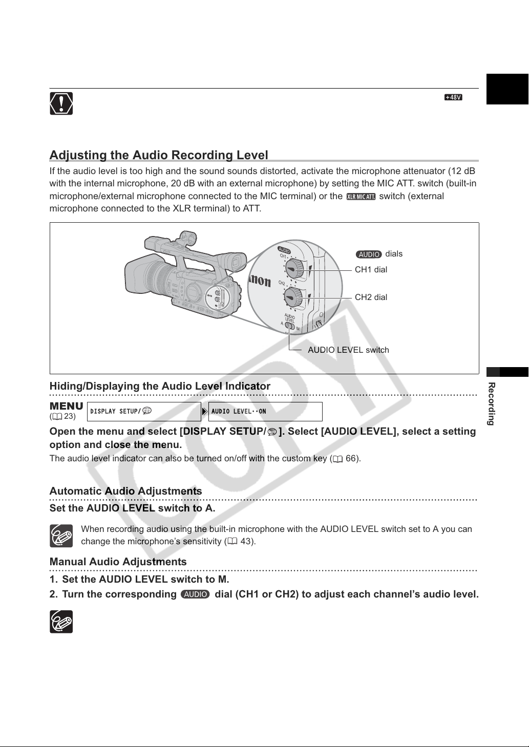
DISPLAY SETUP/ AUDIO LEVEL••ON
Select [XLR GAIN UP], set it to [12dB] and close the menu.
Only effective when the LINE/MIC switch is set to MIC.
When connecting a microphone that does not support phantom power, make sure to set the
switch to OFF. Otherwise the microphone may be damaged.
Adjusting the Audio Recording Level
If the audio level is too high and the sound sounds distorted, activate the microphone attenuator (12 dB
with the internal microphone, 20 dB with an external microphone) by setting the MIC ATT. switch (built-in
microphone/external microphone connected to the MIC terminal) or the switch (external
microphone connected to the XLR terminal) to ATT.
dials
CH1 dial
CH2 dial
E
AUDIO LEVEL switch
Hiding/Displaying the Audio Level Indicator
MENU
(23)
Open the menu and select [DISPLAY SETUP/ ]. Select [AUDIO LEVEL], select a setting
option and close the menu.
The audio level indicator can also be turned on/off with the custom key ( 66).
Automatic Audio Adjustments
Set the AUDIO LEVEL switch to A.
When recording audio using the built-in microphone with the AUDIO LEVEL switch set to A you can
change the microphone’s sensitivity ( 43).
Manual Audio Adjustments
1. Set the AUDIO LEVEL switch to M.
2. Turn the corresponding dial (CH1 or CH2) to adjust each channel’s audio level.
We recommend using headphones when adjusting the audio level. If the input level is too high,
audio may become distorted even if the audio level indicator shows an appropriate level. Use
commercially available headphones with a cable no longer than 3 m.
You can select to synchronize the audio signal with the video signal by adding an equal amount of
delay to the audio. Open the menu and select [AUDIO SETUP]. Select [AUD.M.SET], set it to [LINE
OUT] and close the menu. If you wish to monitor audio in real time, select [NORMAL] instead. In
either setting, the audio and video signals recorded on the tape will be synchronized.
Recording
45
Page 46
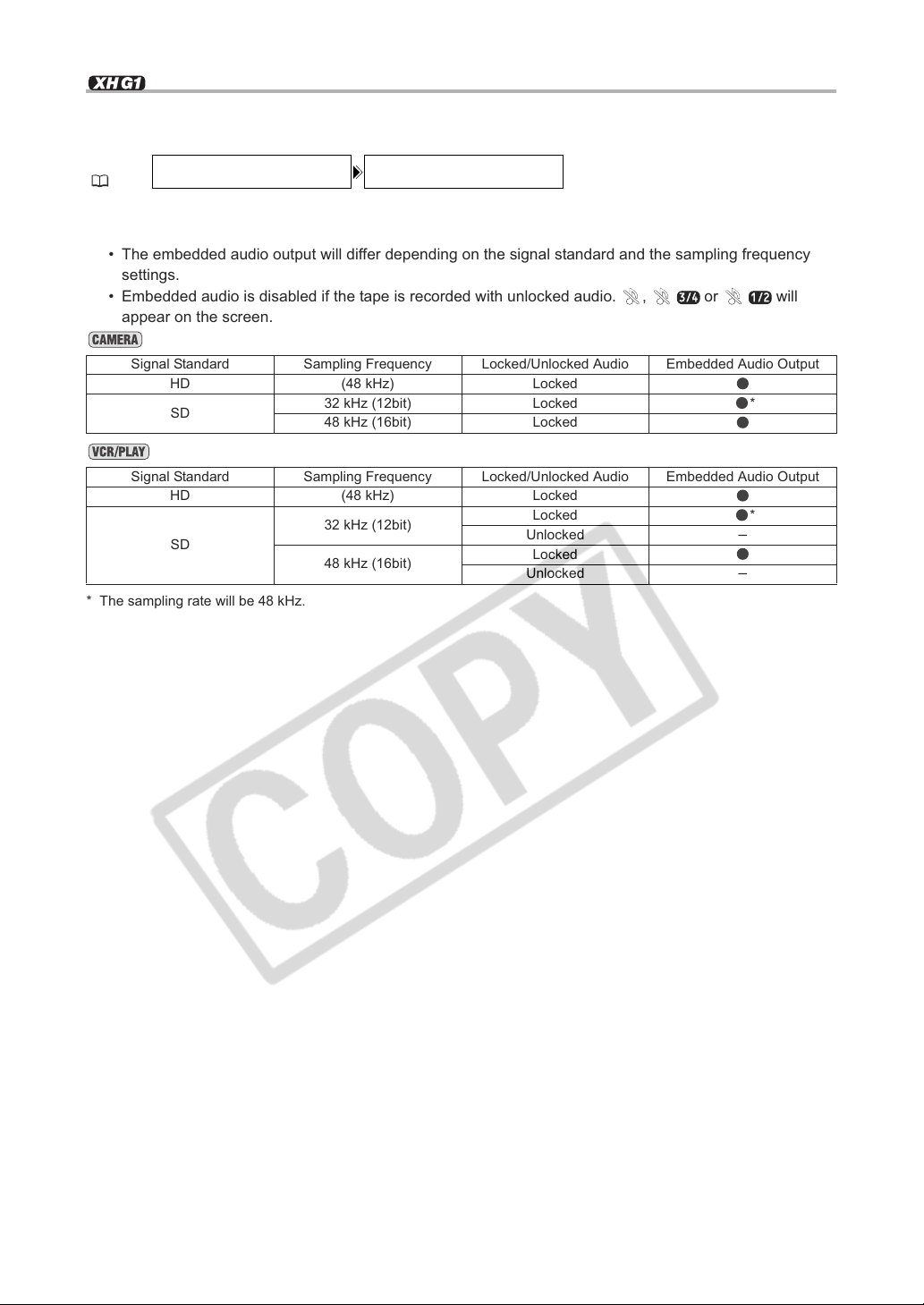
Embedded Audio
SIGNAL SETUP SDI OUTPUT••OFF
3/4 1/2
Embedded audio refers to the superimposing of the audio signal along with the video signal being output
from the HD/SD SDI terminal.
MENU
(23)
Open the menu and select [SIGNAL SETUP]. Select [SDI OUTPUT], set it to [ON] and
close the menu.
• The embedded audio output will differ depending on the signal standard and the sampling frequency
settings.
• Embedded audio is disabled if the tape is recorded with unlocked audio. , or will
appear on the screen.
Signal Standard Sampling Frequency Locked/Unlocked Audio Embedded Audio Output
HD (48 kHz) Locked
SD
Signal Standard Sampling Frequency Locked/Unlocked Audio Embedded Audio Output
HD (48 kHz) Locked
SD
* The sampling rate will be 48 kHz.
32 kHz (12bit) Locked *
48 kHz (16bit) Locked
32 kHz (12bit)
48 kHz (16bit)
Locked *
Unlocked
Locked
Unlocked
–
–
46
Page 47
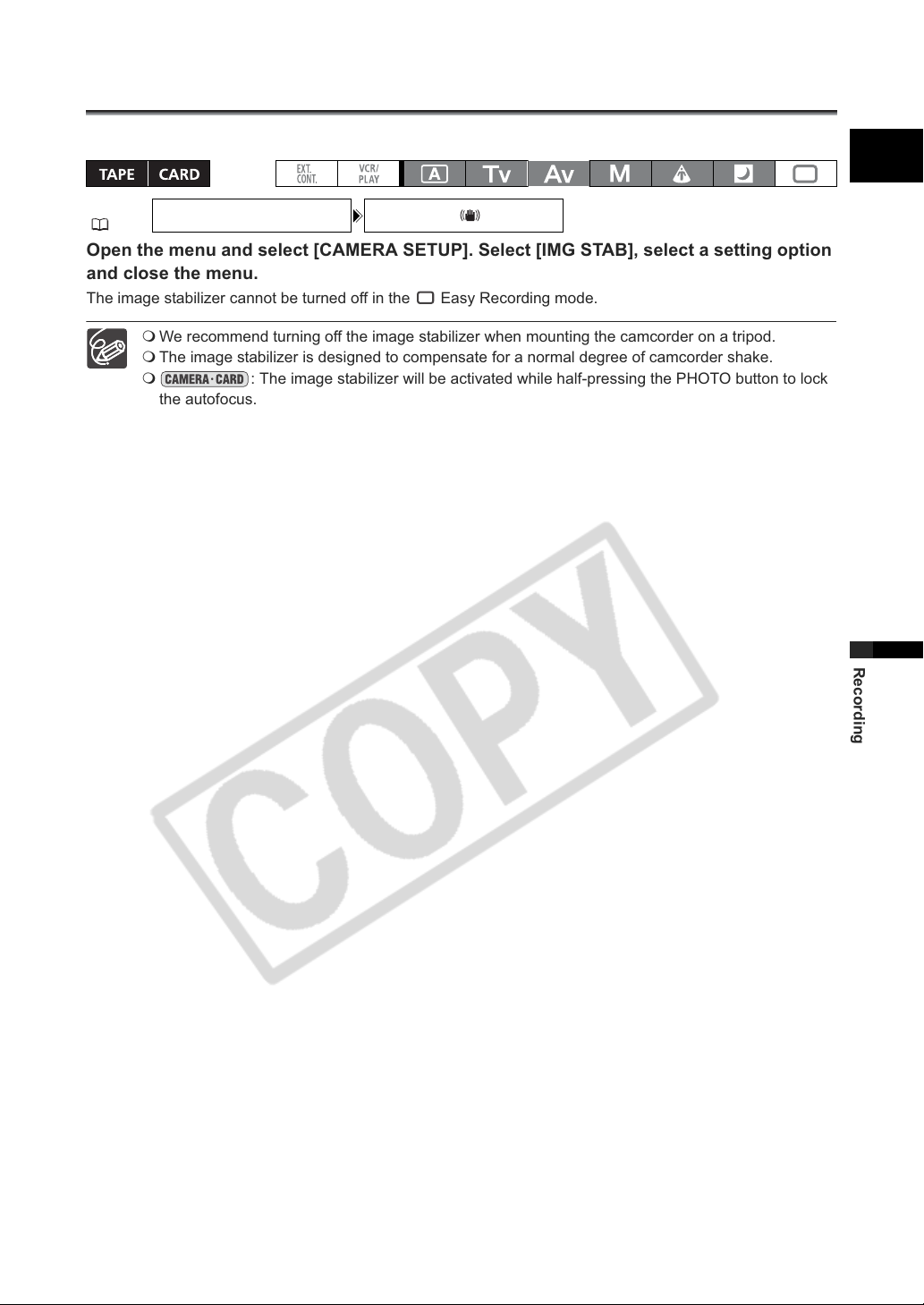
Image Stabilizer
CAMERA SETUP IMG STAB
ON
You can select to activate or turn off the image stabilizer depending on the recording conditions.
E
MENU
(23)
•••
Open the menu and select [CAMERA SETUP]. Select [IMG STAB], select a setting option
and close the menu.
The image stabilizer cannot be turned off in the Easy Recording mode.
We recommend turning off the image stabilizer when mounting the camcorder on a tripod.
The image stabilizer is designed to compensate for a normal degree of camcorder shake.
: The image stabilizer will be activated while half-pressing the PHOTO button to lock
the autofocus.
Recording
47
Page 48
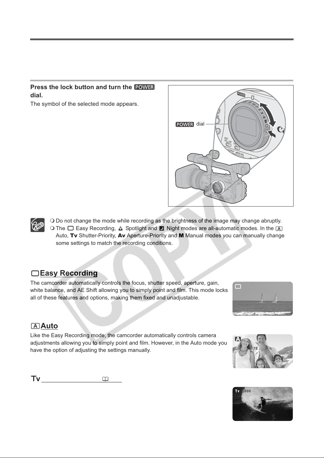
Using the Programmed AE Modes
Programmed auto exposure modes provide advanced automated recording techniques ensuring
professional results in various shooting conditions.
Selecting the Programmed AE Modes
Press the lock button and turn the
dial.
The symbol of the selected mode appears.
dial
Do not change the mode while recording as the brightness of the image may change abruptly.
The Easy Recording, Spotlight and Night modes are all-automatic modes. In the
Auto, Tv Shutter-Priority, Av Aperture-Priority and M Manual modes you can manually change
some settings to match the recording conditions.
Easy Recording
The camcorder automatically controls the focus, shutter speed, aperture, gain,
white balance, and AE Shift allowing you to simply point and film. This mode locks
all of these features and options, making them fixed and unadjustable.
Auto
Like the Easy Recording mode, the camcorder automatically controls camera
adjustments allowing you to simply point and film. However, in the Auto mode you
have the option of adjusting the settings manually.
Shutter-Priority ( 51)
Use this mode to select the shutter speed. The camcorder automatically sets a
matching aperture setting.
48
Page 49
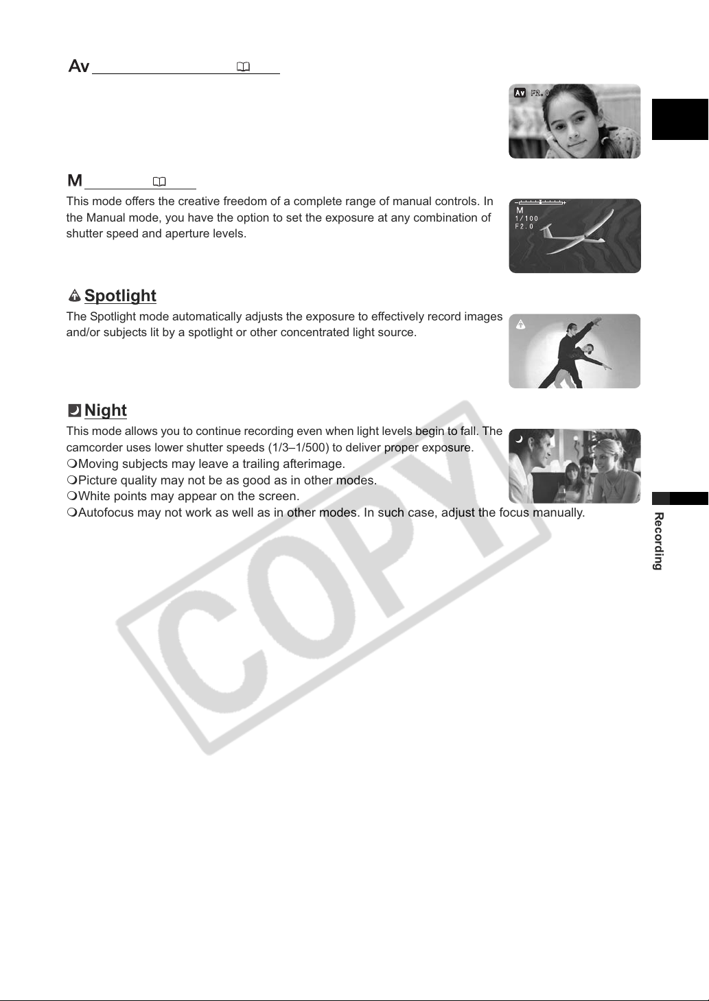
Aperture-Priority ( 52)
Use this mode to select between 7 aperture settings –from f/1.6 to f/9.5 (or to full iris
close)– and the camcorder automatically sets a matching shutter speed. This mode
allows for the best control of depth of field.
Manual ( 53)
This mode offers the creative freedom of a complete range of manual controls. In
the Manual mode, you have the option to set the exposure at any combination of
shutter speed and aperture levels.
Spotlight
The Spotlight mode automatically adjusts the exposure to effectively record images
and/or subjects lit by a spotlight or other concentrated light source.
Night
This mode allows you to continue recording even when light levels begin to fall. The
camcorder uses lower shutter speeds (1/3–1/500) to deliver proper exposure.
Moving subjects may leave a trailing afterimage.
Picture quality may not be as good as in other modes.
White points may appear on the screen.
Autofocus may not work as well as in other modes. In such case, adjust the focus manually.
E
Recording
49
Page 50
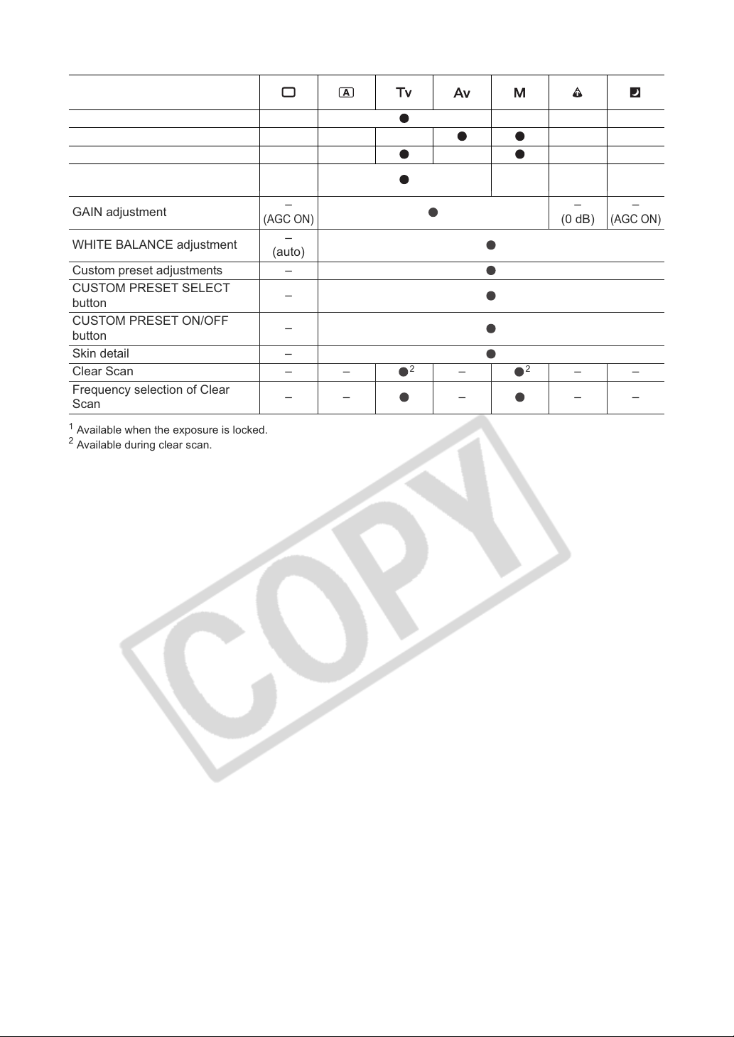
Availability of functions in each recording program
Recording programs
EXP. LOCK button – – – –
Iris ring – –
SHUTTER dial – –
AE shift adjustment
GAIN adjustment
WHITE BALANCE adjustment
–
(0)
–
(AGC ON)
–
(auto)
1
1
1
–
1
–
–
––
––
–
(0)
–
(0 dB)
(AGC ON)
Custom preset adjustments –
CUSTOM PRESET SELECT
button
CUSTOM PRESET ON/OFF
button
–
–
Skin detail –
Clear Scan – –
Frequency selection of Clear
Scan
1
Available when the exposure is locked.
2
Available during clear scan.
–––––
2
–
2
––
–
(0)
–
50
Page 51
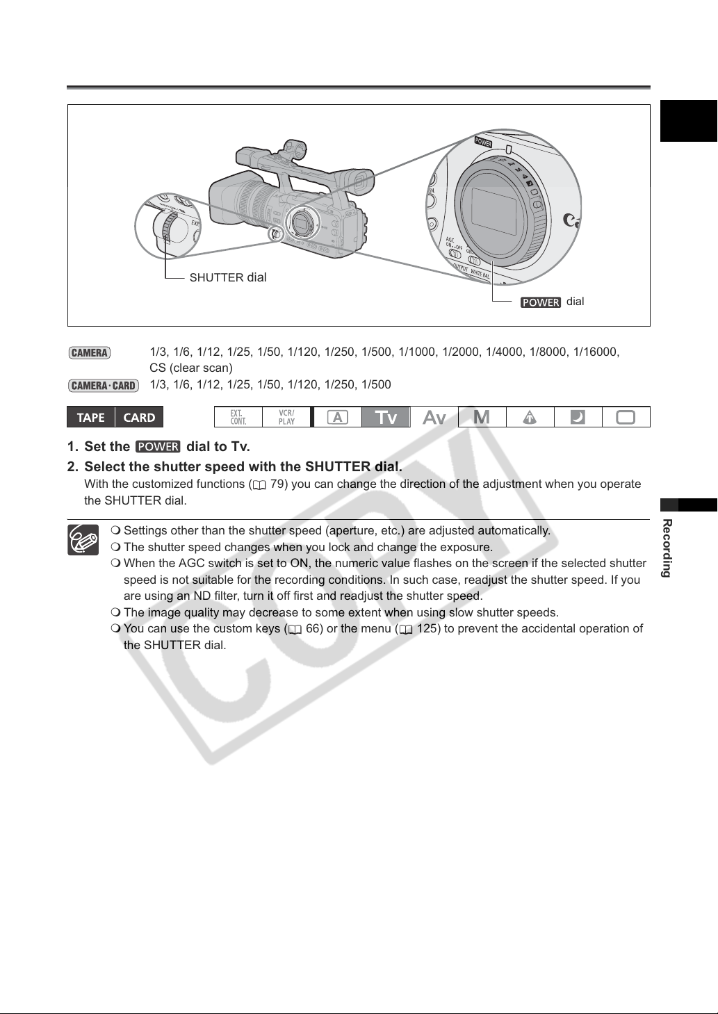
Recording in the Shutter-Priority (Tv) Mode
SHUTTER dial
dial
1/3, 1/6, 1/12, 1/25, 1/50, 1/120, 1/250, 1/500, 1/1000, 1/2000, 1/4000, 1/8000, 1/16000,
CS (clear scan)
1/3, 1/6, 1/12, 1/25, 1/50, 1/120, 1/250, 1/500
1. Set the dial to Tv.
2. Select the shutter speed with the SHUTTER dial.
With the customized functions ( 79) you can change the direction of the adjustment when you operate
the SHUTTER dial.
Settings other than the shutter speed (aperture, etc.) are adjusted automatically.
The shutter speed changes when you lock and change the exposure.
When the AGC switch is set to ON, the numeric value flashes on the screen if the selected shutter
speed is not suitable for the recording conditions. In such case, readjust the shutter speed. If you
are using an ND filter, turn it off first and readjust the shutter speed.
The image quality may decrease to some extent when using slow shutter speeds.
You can use the custom keys ( 66) or the menu ( 125) to prevent the accidental operation of
the SHUTTER dial.
E
Recording
51
Page 52
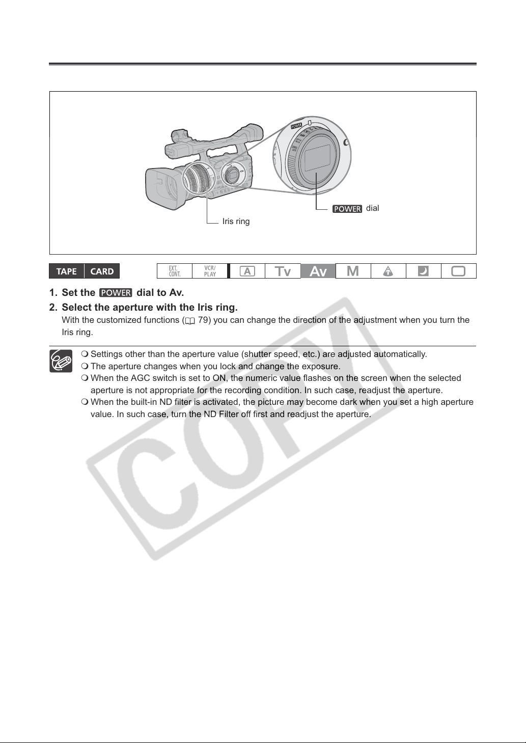
Recording in the Aperture-Priority (Av) Mode
You can select an aperture value in the range F1.6 to F9.5 or CLOSE.
dial
Iris ring
1. Set the dial to Av.
2. Select the aperture with the Iris ring.
With the customized functions ( 79) you can change the direction of the adjustment when you turn the
Iris ring.
Settings other than the aperture value (shutter speed, etc.) are adjusted automatically.
The aperture changes when you lock and change the exposure.
When the AGC switch is set to ON, the numeric value flashes on the screen when the selected
aperture is not appropriate for the recording condition. In such case, readjust the aperture.
When the built-in ND filter is activated, the picture may become dark when you set a high aperture
value. In such case, turn the ND Filter off first and readjust the aperture.
52
Page 53
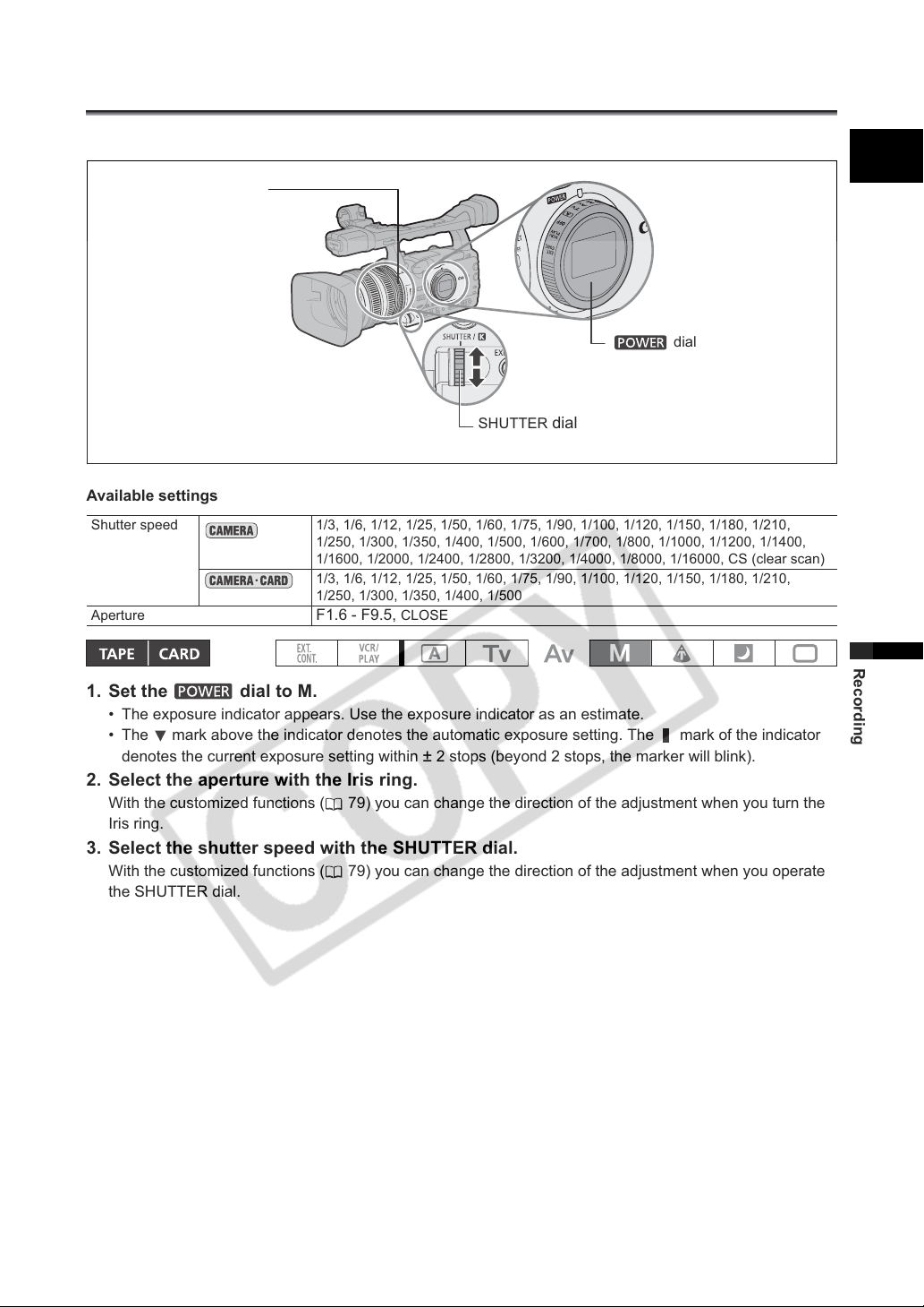
Recording in the Manual Mode
You can set the exposure at any combination of shutter speed and aperture.
Iris ring
E
dial
SHUTTER
Available settings
Shutter speed 1/3, 1/6, 1/12, 1/25, 1/50, 1/60, 1/75, 1/90, 1/100, 1/120, 1/150, 1/180, 1/210,
Aperture
1/250, 1/300, 1/350, 1/400, 1/500, 1/600, 1/700, 1/800, 1/1000, 1/1200, 1/1400,
1/1600, 1/2000, 1/2400, 1/2800, 1/3200, 1/4000, 1/8000, 1/16000, CS (clear scan)
1/3, 1/6, 1/12, 1/25, 1/50, 1/60, 1/75, 1/90, 1/100, 1/120, 1/150, 1/180, 1/210,
1/250, 1/300, 1/350, 1/400, 1/500
F1.6 - F9.5, CLOSE
dial
1. Set the dial to M.
• The exposure indicator appears. Use the exposure indicator as an estimate.
• The mark above the indicator denotes the automatic exposure setting. The mark of the indicator
denotes the current exposure setting within
± 2 stops (beyond 2 stops, the marker will blink).
2. Select the aperture with the Iris ring.
With the customized functions ( 79) you can change the direction of the adjustment when you turn the
Iris ring.
3. Select the shutter speed with the SHUTTER dial.
With the customized functions ( 79) you can change the direction of the adjustment when you operate
the SHUTTER dial.
Recording
53
Page 54
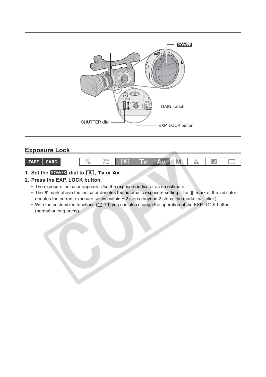
Adjusting the Exposure
Iris ring
dial
GAIN switch
SHUTTER
dial
EXP. LOCK button
Exposure Lock
1. Set the dial to , Tv or Av.
2. Press the EXP. LOCK button.
• The exposure indicator appears. Use the exposure indicator as an estimate.
• The mark above the indicator denotes the automatic exposure setting. The mark of the indicator
denotes the current exposure setting within
• With the customized functions ( 79) you can also change the operation of the EXP.LOCK button
(normal or long press).
± 2 stops (beyond 2 stops, the marker will blink).
54
Page 55
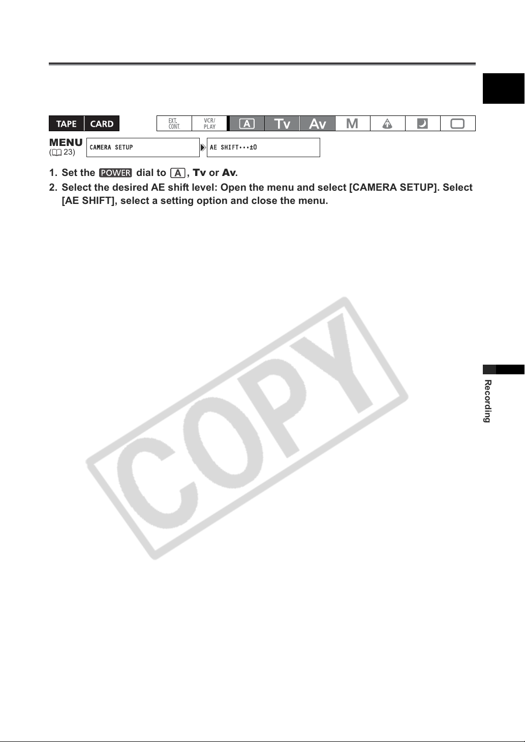
Using AE Shift
CAMERA SETUP AE SHIFT•••±0
You can use the AE Shift control to manually override the automatic exposure system in order to darken
or lighten the image. Select from 15 AE levels (+2.0, +1.5, +1.25, +1.0, +0.75, +0.5, +0.25, ±0, -0.25,
-0.5, -0.75, -1.0, -1.25, -1.5, -2.0).
E
MENU
(23)
1. Set the dial to , Tv or Av.
2. Select the desired AE shift level: Open the menu and select [CAMERA SETUP]. Select
[AE SHIFT], select a setting option and close the menu.
Recording
55
Page 56
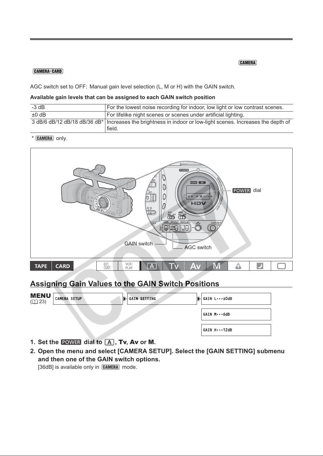
Adjusting the Gain
CAMERA SETUP GAIN SETTING GAIN L•••±0dB
GAIN M•••6dB
GAIN H•••12dB
The gain control adjusts the level of the video signal generated depending on the lighting and shooting
conditions. You can select from automatic gain control or of 3 preset gain levels (L: low, M: middle,
H: high) to which you can independently assign gain values from -3 dB to +36 dB ( ) or +18 dB
().
AGC switch set to ON: Automatic gain control.
AGC switch set to OFF: Manual gain level selection (L, M or H) with the GAIN switch.
Available gain levels that can be assigned to each GAIN switch position
-3 dB For the lowest noise recording for indoor, low light or low contrast scenes.
±0 dB For lifelike night scenes or scenes under artificial lighting.
3 dB/6 dB/12 dB/18 dB/36 dB*
* only.
Increases the brightness in indoor or low-light scenes. Increases the depth of
field.
dial
GAIN switch
AGC switch
Assigning Gain Values to the GAIN Switch Positions
MENU
(23)
1. Set the dial to , Tv, Av or M.
2. Open the menu and select [CAMERA SETUP]. Select the [GAIN SETTING] submenu
3. Select a setting option and press the SELECT/SET dial.
4. Close the menu.
and then one of the GAIN switch options.
[36dB] is available only in mode.
After the adjustment you will return to the [GAIN SETTING] submenu. Assign the gain values to the other
GAIN switch options in the same way.
56
Page 57
Selecting the Gain Level
1. Set the dial to , Tv, Av or M.
2. Set the AGC switch to OFF.
3. Set the GAIN switch to the desired gain position.
When you select high gain values, the picture may flicker slightly. The [36dB] setting in particular
allows you to film with a higher sensitivity but is more prone to the appearance of video noise and
artifacts (white dots, vertical streaks or blocking).
E
Recording
57
Page 58
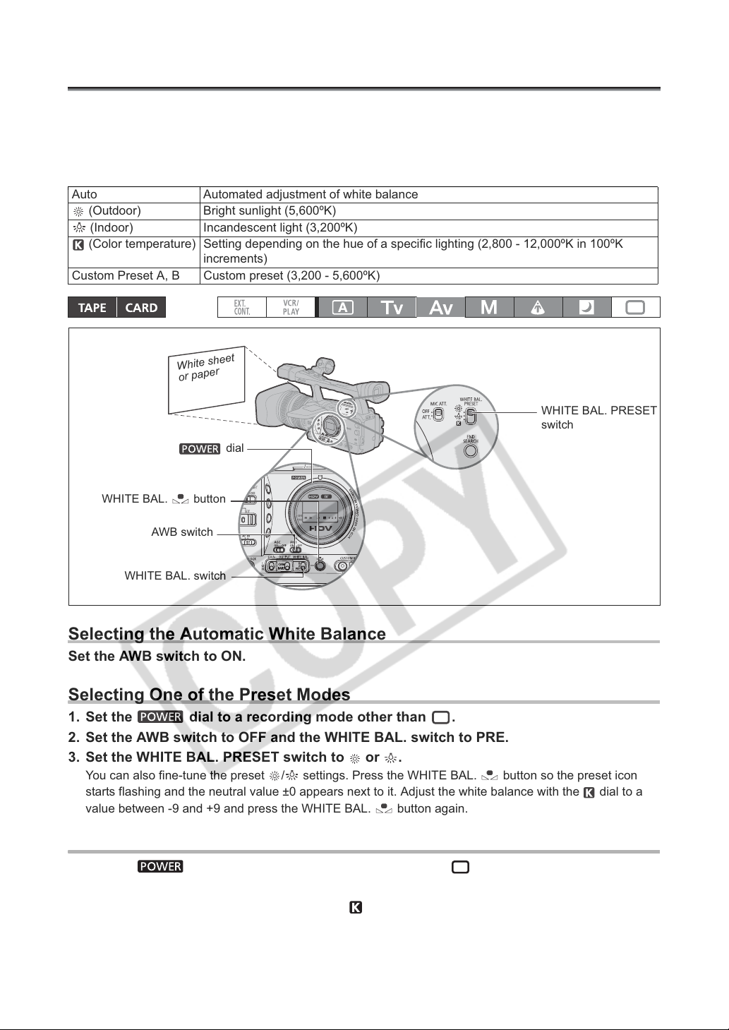
Setting the White Balance
The camcorder uses an electronic white balance process to calibrate the picture for accurate color
display under different lighting conditions.
In addition to the fully automated mode, white balance modes include an indoor mode, an outdoor mode,
a color temperature setting and two user-defined custom preset values.
Auto Automated adjustment of white balance
(Outdoor) Bright sunlight (5,600ºK)
(Indoor) Incandescent light (3,200ºK)
(Color temperature) Setting depending on the hue of a specific lighting (2,800 - 12,000ºK in 100ºK
increments)
Custom Preset A, B Custom preset (3,200 - 5,600ºK)
t
e
e
h
e s
t
i
h
W
r
e
p
a
p
r
o
WHITE BAL. PRESET
switch
dial
WHITE BAL. button
AWB switch
WHITE BAL. switch
Selecting the Automatic White Balance
Set the AWB switch to ON.
Selecting One of the Preset Modes
1. Set the dial to a recording mode other than .
2. Set the AWB switch to OFF and the WHITE BAL. switch to PRE.
3. Set the WHITE BAL. PRESET switch to or .
You can also fine-tune the preset / settings. Press the WHITE BAL. button so the preset icon
starts flashing and the neutral value ±0 appears next to it. Adjust the white balance with the dial to a
value between -9 and +9 and press the WHITE BAL. button again.
Setting the Color Temperature
1. Set the dial to a recording program other than .
2. Set the AWB switch to OFF and the WHITE BAL. switch to PRE.
3. Set the WHITE BAL. PRESET switch to .
The color temperature currently set will be displayed.
58
Page 59
4. Press the WHITE BAL. button.
The color temperature display will start flashing.
5. Turn the dial to set the desired color temperature.
6. Press the WHITE BAL. button again.
The color temperature display stops flashing and stays on.
Setting a Custom White Balance
1. Set the dial to a recording program other than .
2. Set the AWB switch to OFF and the WHITE BAL. switch to one of the custom presets,
A or B.
and the corresponding letter will flash on the screen.
3. Point the camcorder at a white object and zoom in until it fills the whole screen.
Keep the camcorder zoomed at the white object until step 4 is completed.
4. Press the WHITE BAL. button.
and the corresponding letter will stop flashing and stay on when the setting is completed.
When you set the custom white balance: Very rarely and depending on the light source, may
keep flashing. The result will still be better than with the auto setting.
As long as the built-in rechargeable lithium battery is charged, the camcorder retains the custom
white balance setting even if you turn it off.
The following custom preset settings take precedence, and will override the white balance set with
the procedure above: The Color Matrix [CMX] setting, the 3 R/G/B Gain settings, and the 6 R/G/B
Matrix settings ( 73).
The custom white balance may provide better results in the following cases:
- Changing lighting conditions
-Close-ups
- Subjects in a single color (sky, sea or forest)
- Under mercury lamps or certain types of fluorescent lights
Perform the custom white balance setting procedure in a sufficiently well lit place.
Readjust the custom white balance if you turn the built-in ND filter on/off or when the light source
has changed.
E
Recording
Recording with Preset Custom White Balance
1. Set the dial to a recording program other than .
2. Set the AWB switch to OFF and the WHITE BAL. switch to the desired custom preset,
A or B.
The custom white balance is activated.
59
Page 60
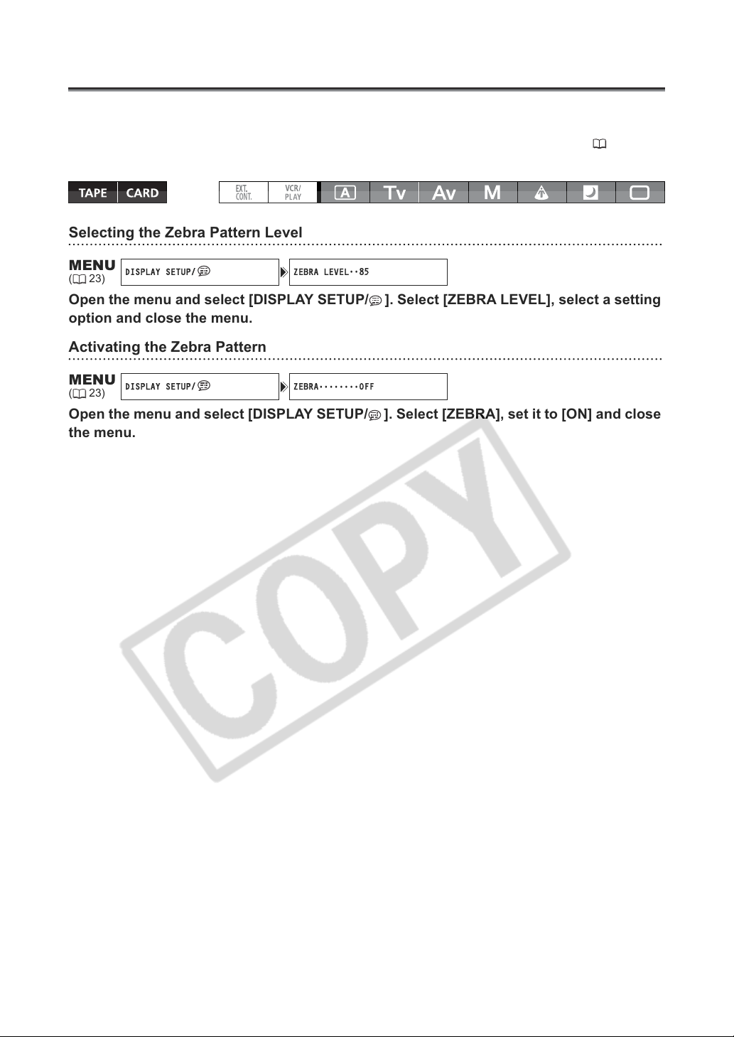
Using the Zebra Pattern
DISPLAY SETUP/ ZEBRA LEVEL••85
DISPLAY SETUP/ ZEBRA
OFF
This camcorder has a zebra pattern feature that shows black and white diagonal stripes over the area
that is overexposed. The zebra pattern is only displayed on the screen and will not affect your
recordings. The zebra pattern will not be displayed while using the Peaking assist function ( 35).
Available zebra pattern settings: 70 IRE, 75 IRE, 80 IRE, 85 IRE, 90 IRE, 95 IRE, and 100 IRE.
Selecting the Zebra Pattern Level
MENU
(23)
Open the menu and select [DISPLAY SETUP/ ]. Select [ZEBRA LEVEL], select a setting
option and close the menu.
Activating the Zebra Pattern
MENU
(23)
••••••••
Open the menu and select [DISPLAY SETUP/ ]. Select [ZEBRA], set it to [ON] and close
the menu.
60
Page 61
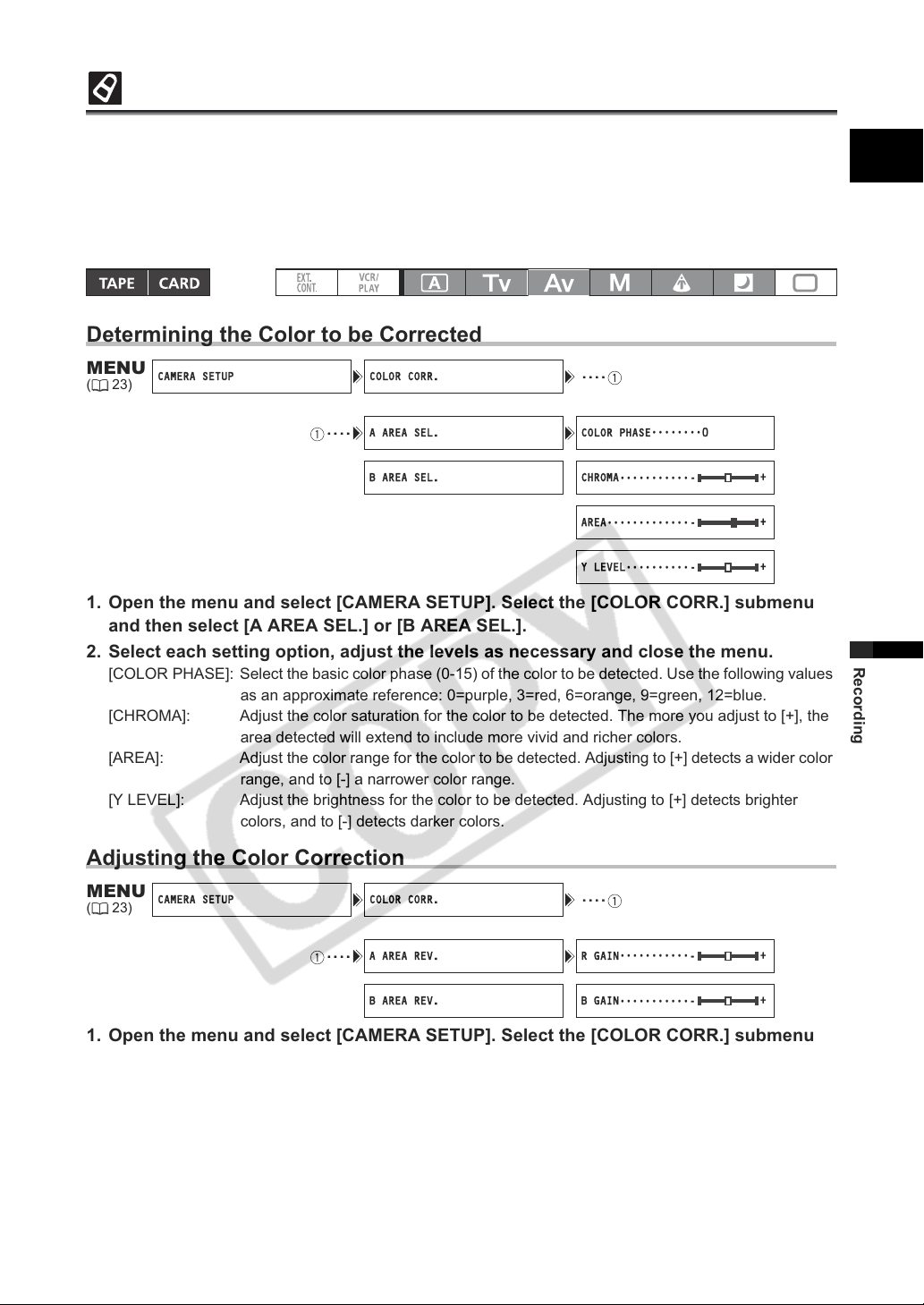
Using the Color Correction
CAMERA SETUP COLOR CORR. ····
····
A AREA SEL. COLOR PHASE
0
B AREA SEL. CHROMA
- +
AREA
- +
Y LEVEL
- +
CAMERA SETUP COLOR CORR. ····
····
A AREA REV. R GAIN
- +
B AREA REV. B GAIN
- +
With the color correction function you can set the camcorder to detect the characteristics of a certain
color or pattern (color phase, chroma, area and Y level) and correct them automatically when recording.
You can set the color correction for up to two different colors (A and B).
When determining the color to be corrected, the areas that will be corrected appear on the screen as a
zebra pattern alternating with the normal picture. On a connected monitor or computer, those areas will
appear instead as white areas alternating with the normal picture.
Determining the Color to be Corrected
E
MENU
(23)
••••••••
•••••••••••
•••••••••••••
••••••••••
1. Open the menu and select [CAMERA SETUP]. Select the [COLOR CORR.] submenu
and then select [A AREA SEL.] or [B AREA SEL.].
2. Select each setting option, adjust the levels as necessary and close the menu.
[COLOR PHASE]: Select the basic color phase (0-15) of the color to be detected. Use the following values
as an approximate reference: 0=purple, 3=red, 6=orange, 9=green, 12=blue.
[CHROMA]: Adjust the color saturation for the color to be detected. The more you adjust to [+], the
area detected will extend to include more vivid and richer colors.
[AREA]: Adjust the color range for the color to be detected. Adjusting to [+] detects a wider color
range, and to [-] a narrower color range.
[Y LEVEL]: Adjust the brightness for the color to be detected. Adjusting to [+] detects brighter
colors, and to [-] detects darker colors.
Adjusting the Color Correction
Recording
MENU
(23)
•••••••••••
•••••••••••
1. Open the menu and select [CAMERA SETUP]. Select the [COLOR CORR.] submenu
and then select [A AREA REV.] or [B AREA REV.].
2. Select the color gain options, adjust the levels as necessary and close the menu.
[R GAIN]: Adjust the red gain of the detected area. Adjusting to [+] results in stronger red tones, and to [-]
in stronger cyan tones.
[B GAIN]: Adjust the blue gain of the detected area. Adjusting to [+] results in stronger blue tones, and to
[-] in stronger yellow tones.
61
Page 62

Activating the Color Correction
CAMERA SETUP COLOR CORR. CORRECT
OFF
MENU
(23)
•••••••
1. Open the menu and select [CAMERA SETUP] and select the [COLOR CORR.]
submenu.
2. Select [CORRECT], select a correction mode other than [OFF] to correct only area A,
only area B or both and then close the menu.
62
Page 63
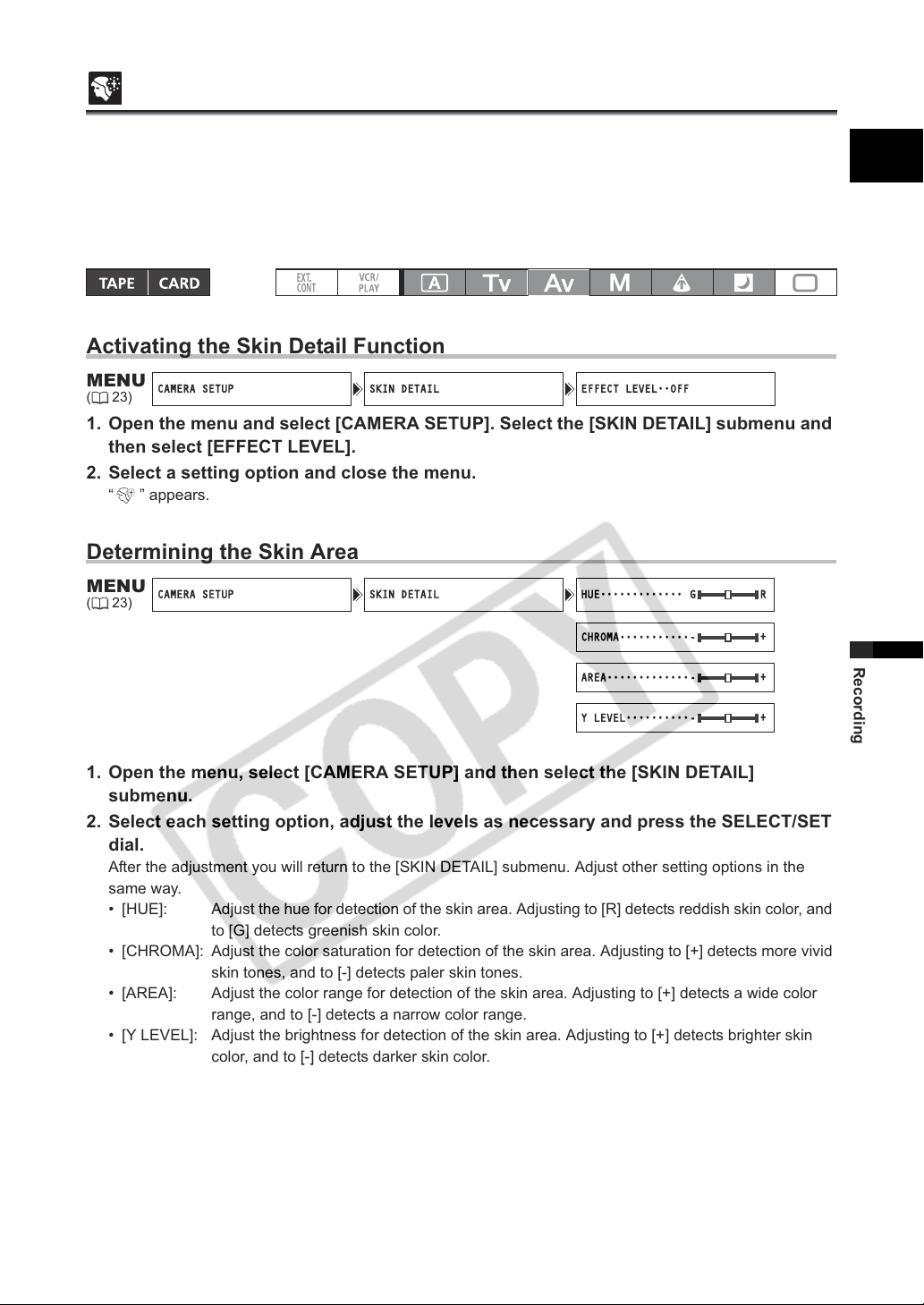
Using the Skin Detail Function
CAMERA SETUP SKIN DETAIL EFFECT LEVEL••OFF
CAMERA SETUP SKIN DETAIL HUE
G R
CHROMA
- +
AREA
- +
Y LEVEL
- +
With the skin detail function, areas in the picture that have skin-tone characteristics will be detected, and
the details in these areas will be softened in order to conceal skin imperfections. On the screen, those
skin areas will be identified by a zebra pattern alternating with the normal picture (on a connected TV or
computer screen they will appear in white instead).
You can adjust the hue, chroma, area and Y level as required, to determine the areas that will be
detected as skin areas.
Activating the Skin Detail Function
E
MENU
(23)
1. Open the menu and select [CAMERA SETUP]. Select the [SKIN DETAIL] submenu and
then select [EFFECT LEVEL].
2. Select a setting option and close the menu.
“ ” appears.
Determining the Skin Area
MENU
(23)
1. Open the menu, select [CAMERA SETUP] and then select the [SKIN DETAIL]
submenu.
2. Select each setting option, adjust the levels as necessary and press the SELECT/SET
dial.
After the adjustment you will return to the [SKIN DETAIL] submenu. Adjust other setting options in the
same way.
• [HUE]: Adjust the hue for detection of the skin area. Adjusting to [R] detects reddish skin color, and
to [G] detects greenish skin color.
• [CHROMA]: Adjust the color saturation for detection of the skin area. Adjusting to [+] detects more vivid
skin tones, and to [-] detects paler skin tones.
• [AREA]: Adjust the color range for detection of the skin area. Adjusting to [+] detects a wide color
range, and to [-] detects a narrow color range.
• [Y LEVEL]: Adjust the brightness for detection of the skin area. Adjusting to [+] detects brighter skin
color, and to [-] detects darker skin color.
3. Close the menu.
•••••••••••••
•••••••••••
•••••••••••••
••••••••••
Recording
63
Page 64
Using the Sky Detail
CAMERA SETUP SKY DETAIL
OFF
With the sky detail function, blue sky areas in the picture will be detected and the detail level in these
areas will be decreased to obtain a softer picture.
MENU
(23)
To activate the sky detail effect:
••••
Open the menu and select [CAMERA SETUP]. Select [SKY DETAIL], set it to [SOFT ]
and close the menu.
64
Page 65
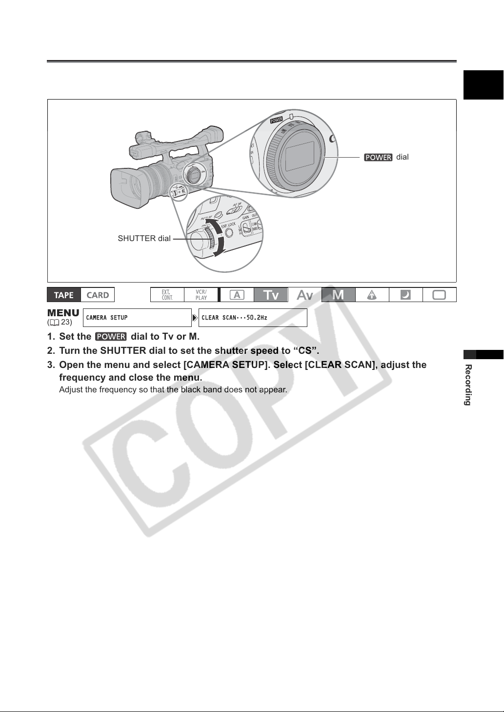
Using the Clear Scan Function
CAMERA SETUP CLEAR SCAN
50.2Hz
This feature allows you to record a computer’s CRT screen or other equipment without displaying black
band or flicker on the screen. You can adjust the frequency from 50.2 Hz to 200.3 Hz.
dial
SHUTTER dial
E
MENU
(23)
•••
1. Set the dial to Tv or M.
2. Turn the SHUTTER dial to set the shutter speed to “CS”.
3. Open the menu and select [CAMERA SETUP]. Select [CLEAR SCAN], adjust the
frequency and close the menu.
Adjust the frequency so that the black band does not appear.
Recording
65
Page 66
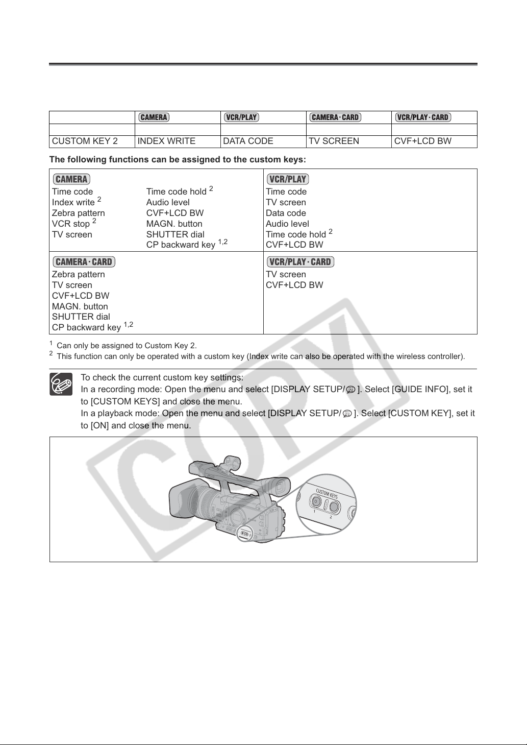
Using the Custom Keys
You can assign frequently used functions to the custom keys. The custom keys can have different
functions assigned to them in each of the operation modes.
Default settings:
CUSTOM KEY 1 TIME CODE TV SCREEN ZEBRA TV SCREEN
CUSTOM KEY 2 INDEX WRITE DATA CODE TV SCREEN CVF+LCD BW
The following functions can be assigned to the custom keys:
Time code
Index write
Zebra pattern
VCR stop
2
TV screen
Zebra pattern
TV screen
2
Time code hold
Audio level
CVF+LCD BW
MAGN. button
SHUTTER dial
CP backward key
2
Time code
TV screen
Data code
1,2
Audio level
Time code hold
CVF+LCD BW
2
TV screen
CVF+LCD BW
CVF+LCD BW
MAGN. button
SHUTTER dial
CP backward key
1
Can only be assigned to Custom Key 2.
2
This function can only be operated with a custom key (Index write can also be operated with the wireless controller).
1,2
To check the current custom key settings:
In a recording mode: Open the menu and select [DISPLAY SETUP/ ]. Select [GUIDE INFO], set it
to [CUSTOM KEYS] and close the menu.
In a playback mode: Open the menu and select [DISPLAY SETUP/ ]. Select [CUSTOM KEY], set it
to [ON] and close the menu.
66
Page 67
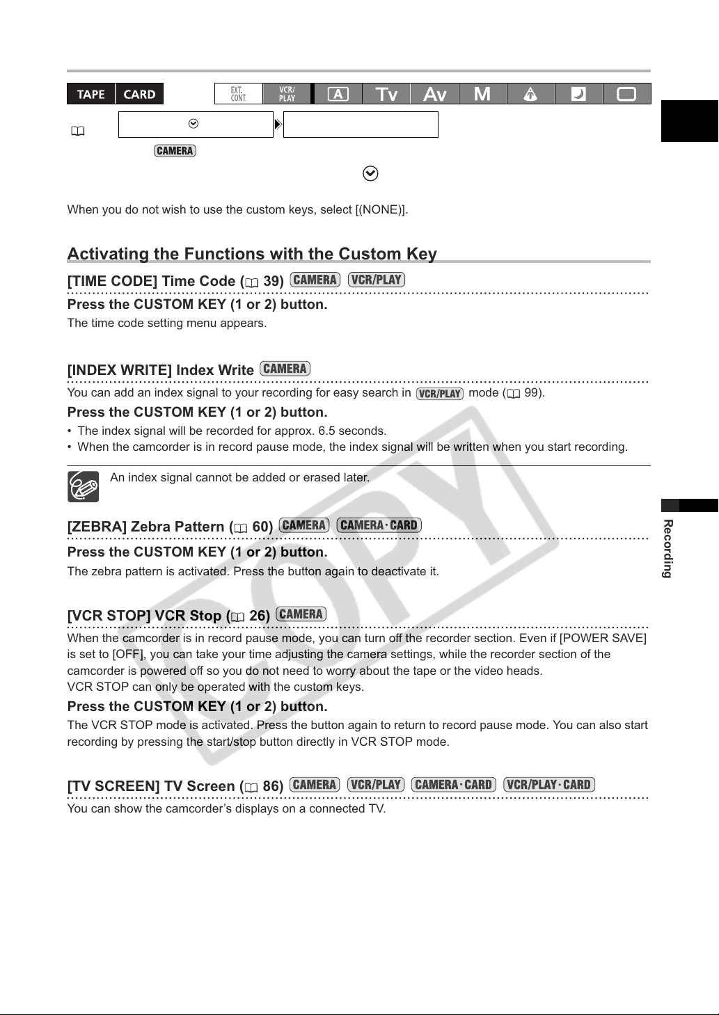
Changing the Custom Keys Setting
SYSTEM SETUP/ CUSTOM KEY 1•INDEX WRITE*
MENU
(23)
* Default value in mode.
Open the menu and select [SYSTEM SETUP/ ]. Select [CUSTOM KEY 1] or [CUSTOM
KEY 2], select the function you wish to assign to the custom key and close the menu.
When you do not wish to use the custom keys, select [(NONE)].
Activating the Functions with the Custom Key
[TIME CODE] Time Code ( 39)
Press the CUSTOM KEY (1 or 2) button.
The time code setting menu appears.
[INDEX WRITE] Index Write
You can add an index signal to your recording for easy search in mode ( 99).
Press the CUSTOM KEY (1 or 2) button.
• The index signal will be recorded for approx. 6.5 seconds.
• When the camcorder is in record pause mode, the index signal will be written when you start recording.
An index signal cannot be added or erased later.
[ZEBRA] Zebra Pattern ( 60)
E
Recording
Press the CUSTOM KEY (1 or 2) button.
The zebra pattern is activated. Press the button again to deactivate it.
[VCR STOP] VCR Stop ( 26)
When the camcorder is in record pause mode, you can turn off the recorder section. Even if [POWER SAVE]
is set to [OFF], you can take your time adjusting the camera settings, while the recorder section of the
camcorder is powered off so you do not need to worry about the tape or the video heads.
VCR STOP can only be operated with the custom keys.
Press the CUSTOM KEY (1 or 2) button.
The VCR STOP mode is activated. Press the button again to return to record pause mode. You can also start
recording by pressing the start/stop button directly in VCR STOP mode.
[TV SCREEN] TV Screen ( 86)
You can show the camcorder’s displays on a connected TV.
Press the CUSTOM KEY (1 or 2) button.
67
Page 68
[TC HOLD] Time Code Hold
You can press the custom key button to freeze the display of the time code. The time code will continue
running normally even while the time code display is on hold.
Time Code Hold can only be operated with the custom keys.
Press the CUSTOM KEY (1 or 2) button.
• Pressing the custom key button again will reactivate the normal display of the time code.
• While on hold, the time code will be displayed with an next to it and “HOLD” will appear on the side panel
display.
• The time code being output from the TIME CODE ( only), HD/SD SDI ( only), LANC and
HDV/DV terminals will not be put on hold. The time code superimposed on the video signal output from the
COMPONENT OUT terminal or the Video terminals will be put on hold.
• The time code hold will be canceled when you turn the camcorder on/off, change the operation mode
between recording and playback or change the position of the / (card/tape) switch.
H
[AUDIO LEVEL] Audio Level Indicator ( 45)
Press the CUSTOM KEY (1 or 2) button.
The audio level indicator appears. Press the button again to hide the audio level indicator.
[CVF+LCD BW] Viewfinder and LCD Screen’s Black & White Display
Press the CUSTOM KEY (1 or 2) button.
The image on both, the viewfinder and the LCD screen, will be shown in black & white (on-screen displays
and indicators will still be displayed in color). Press the button again to return to color display.
[MAGN.B.LOCK] MAGN. Button Lock
Press the CUSTOM KEY (1 or 2) button.
Pressing the button will lock the MAGN. buton to prevent its accidental operation. Press the custom key
button again to reactivate the MAGN. button.
[SHTR D.LOCK] SHUTTER Dial Lock
Press the CUSTOM KEY (1 or 2) button.
Pressing the button will lock the SHUTTER dial to prevent its accidental operation. Press the button again to
reactivate the SHUTTER dial.
[CP BKWD KEY] Custom Preset Backward Key
Press the CUSTOM KEY 2 button.
Usually, pressing the CUSTOM PRESET SELECT button will cycle forwards to the following custom preset
file. Pressing the custom key button will instead cycle backwards to the preceding custom preset file.
Custom Preset Backward Key can only be operated with the custom keys.
[DATA CODE] Data Code ( 101)
Press the CUSTOM KEY (1 or 2) button.
The data code appears. Press the button again to hide the data code.
68
Page 69
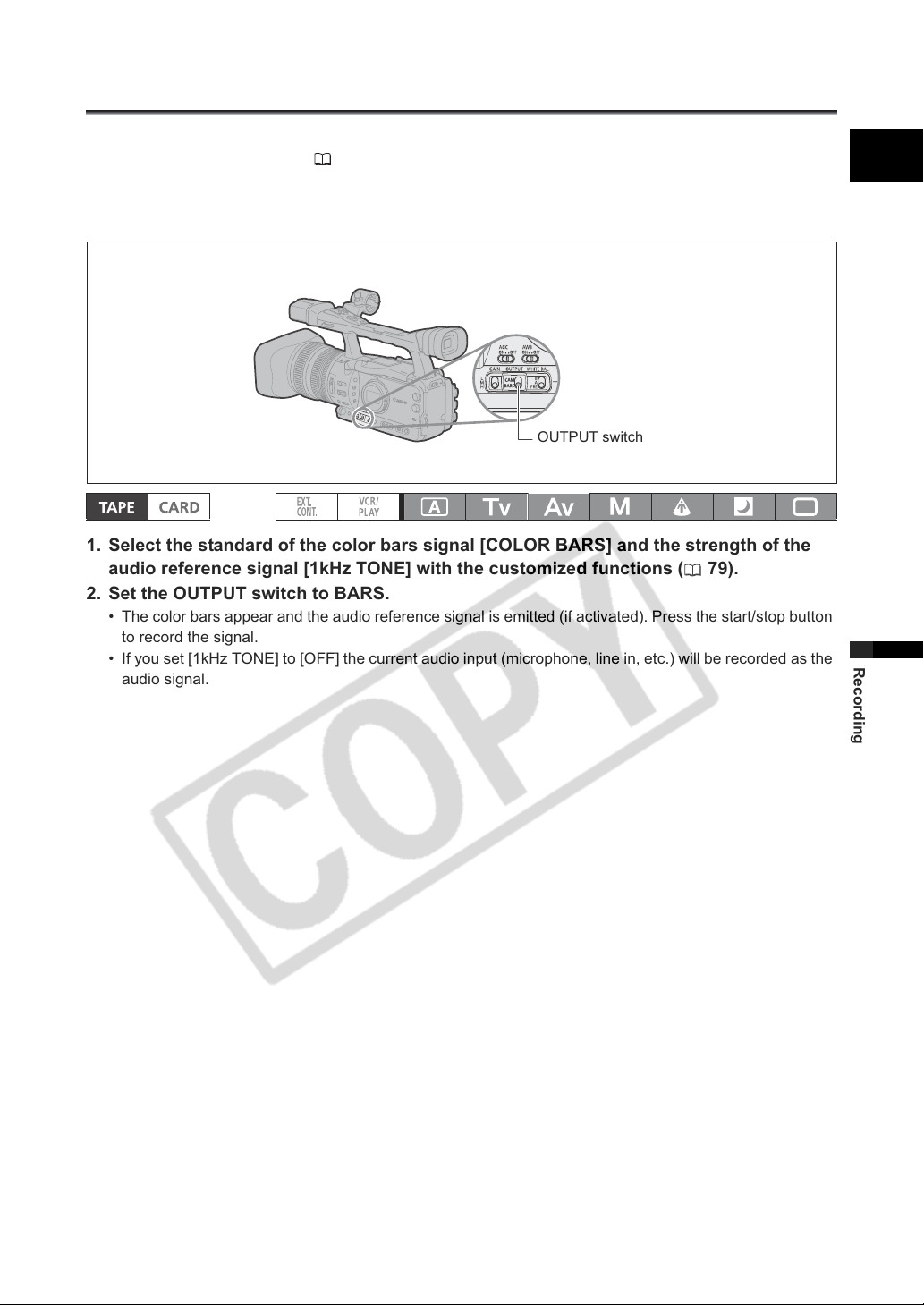
Recording Color Bars/Audio Reference Signal
You can generate and record color bars signals and a 1 kHz audio reference signal.
With the customized functions ( 79) you can choose between EBU* ([TYPE 1]) and SMPTE** color
bars ([TYPE 2]) and you can also select the strength of the audio signal (-12 dB or -20 dB).
* European Broadcast Union.
** Society of Motion Picture and Television Engineers.
OUTPUT switch
1. Select the standard of the color bars signal [COLOR BARS] and the strength of the
audio reference signal [1kHz TONE] with the customized functions ( 79).
2. Set the OUTPUT switch to BARS.
• The color bars appear and the audio reference signal is emitted (if activated). Press the start/stop button
to record the signal.
• If you set [1kHz TONE] to [OFF] the current audio input (microphone, line in, etc.) will be recorded as the
audio signal.
E
Recording
69
Page 70
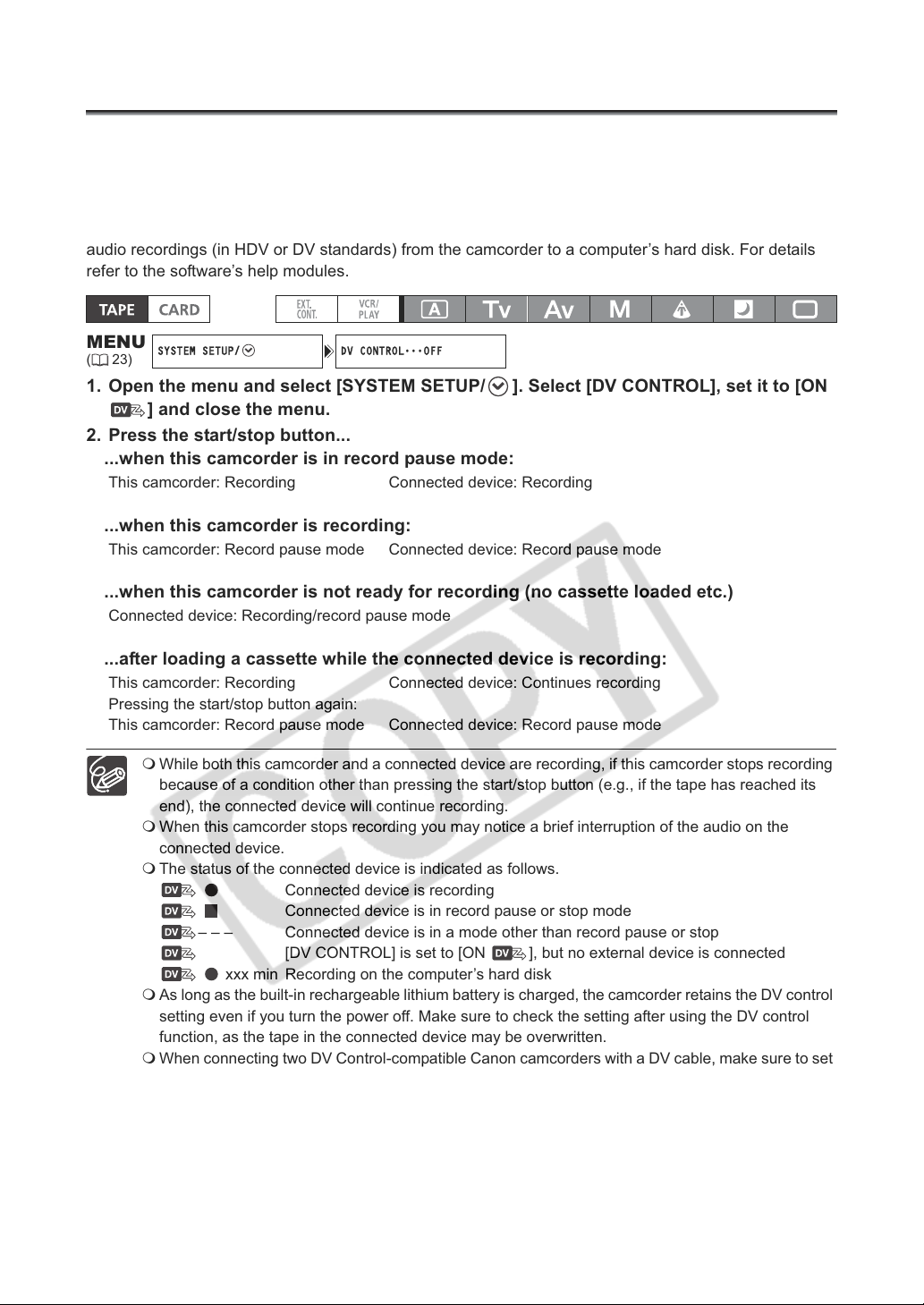
Using the Digital Video Control
SYSTEM SETUP/ DV CONTROL
OFF
This feature enables the camcorder to control the record and stop functions of an external digital device
connected to the camcorder through the HDV/DV terminal. The device must comply with the IEEE1394
AV/C protocol. Use the optional CV-150F (4 pin-4 pin) or CV-250F (4 pin-6 pin) DV cable to connect the
external device.
Windows XP (SP2) users can use the CONSOLE software (sold separately) to download video and
audio recordings (in HDV or DV standards) from the camcorder to a computer’s hard disk. For details
refer to the software’s help modules.
MENU
(23)
•••
1. Open the menu and select [SYSTEM SETUP/ ]. Select [DV CONTROL], set it to [ON
] and close the menu.
2. Press the start/stop button...
...when this camcorder is in record pause mode:
This camcorder: Recording Connected device: Recording
...when this camcorder is recording:
This camcorder: Record pause mode Connected device: Record pause mode
...when this camcorder is not ready for recording (no cassette loaded etc.)
Connected device: Recording/record pause mode
...after loading a cassette while the connected device is recording:
This camcorder: Recording Connected device: Continues recording
Pressing the start/stop button again:
This camcorder: Record pause mode Connected device: Record pause mode
While both this camcorder and a connected device are recording, if this camcorder stops recording
because of a condition other than pressing the start/stop button (e.g., if the tape has reached its
end), the connected device will continue recording.
When this camcorder stops recording you may notice a brief interruption of the audio on the
connected device.
The status of the connected device is indicated as follows.
Connected device is recording
Connected device is in record pause or stop mode
– – – Connected device is in a mode other than record pause or stop
[DV CONTROL] is set to [ON ], but no external device is connected
xxx min Recording on the computer’s hard disk
As long as the built-in rechargeable lithium battery is charged, the camcorder retains the DV control
setting even if you turn the power off. Make sure to check the setting after using the DV control
function, as the tape in the connected device may be overwritten.
When connecting two DV Control-compatible Canon camcorders with a DV cable, make sure to set
[DV CONTROL] on the other connected camcorder to [OFF].
Up to 2 other devices can be connected to the XH G1/XH A1 for DV control.
With some non-Canon devices: The DV control may not work properly depending on the connected
device.
70
Page 71
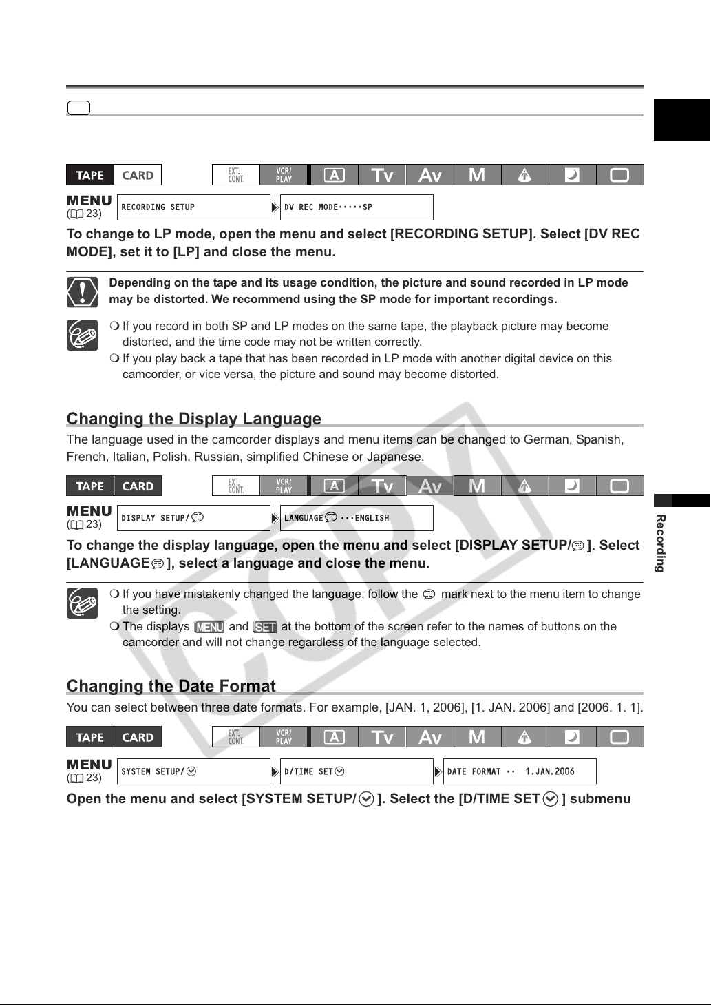
Other Camcorder Functions/Settings
RECORDING SETUP DV REC MODE
SP
DISPLAY SETUP/ LANGUAGE
ENGLISH
SYSTEM SETUP/ D/TIME SET DATE FORMAT
1.JAN.2006
SD
Changing the Recording Mode (SP/LP)
When recording in Standard Definition (SD mode) only, you can choose between SP (standard play)
and LP (long play). LP extends the tape usage by 1.5 times.
E
MENU
(23)
•••••
To change to LP mode, open the menu and select [RECORDING SETUP]. Select [DV REC
MODE], set it to [LP] and close the menu.
Depending on the tape and its usage condition, the picture and sound recorded in LP mode
may be distorted. We recommend using the SP mode for important recordings.
If you record in both SP and LP modes on the same tape, the playback picture may become
distorted, and the time code may not be written correctly.
If you play back a tape that has been recorded in LP mode with another digital device on this
camcorder, or vice versa, the picture and sound may become distorted.
Changing the Display Language
The language used in the camcorder displays and menu items can be changed to German, Spanish,
French, Italian, Polish, Russian, simplified Chinese or Japanese.
MENU
(23)
To change the display language, open the menu and select [DISPLAY SETUP/ ]. Select
[LANGUAGE ], select a language and close the menu.
If you have mistakenly changed the language, follow the mark next to the menu item to change
the setting.
The displays and at the bottom of the screen refer to the names of buttons on the
camcorder and will not change regardless of the language selected.
•••
Recording
Changing the Date Format
You can select between three date formats. For example, [JAN. 1, 2006], [1. JAN. 2006] and [2006. 1. 1].
MENU
(23)
Open the menu and select [SYSTEM SETUP/ ]. Select the [D/TIME SET ] submenu
and then select [DATE FORMAT]. Select a date format and close the menu.
••
71
Page 72
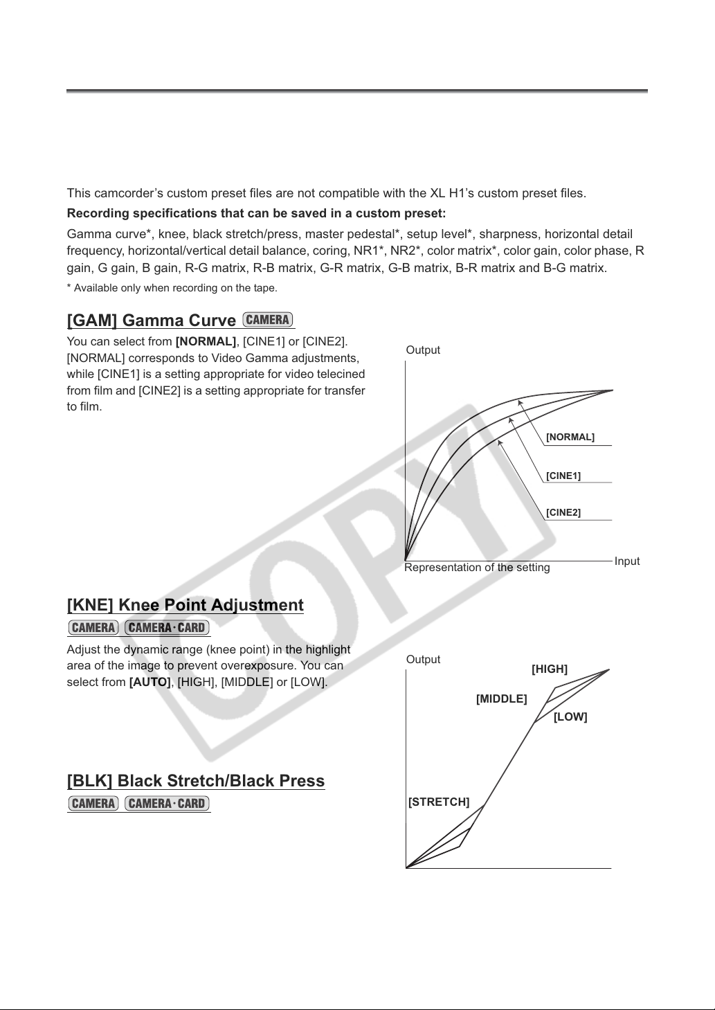
Customization
Using the Custom Preset
You can define preset levels for 23 recording specifications used when recording on tape (17 when
recording still images on the memory card). Up to 9 custom preset files can be saved on the camcorder
(custom preset files 7 - 9 are predefined files) and up to 20 on a memory card. Custom preset files can
be copied from the camcorder to the memory card and vice versa. Also, the custom preset settings
currently in effect can be embedded within a still image of the scene recorded on the memory card.
This camcorder’s custom preset files are not compatible with the XL H1’s custom preset files.
Recording specifications that can be saved in a custom preset:
Gamma curve*, knee, black stretch/press, master pedestal*, setup level*, sharpness, horizontal detail
frequency, horizontal/vertical detail balance, coring, NR1*, NR2*, color matrix*, color gain, color phase, R
gain, G gain, B gain, R-G matrix, R-B matrix, G-R matrix, G-B matrix, B-R matrix and B-G matrix.
* Available only when recording on the tape.
[GAM] Gamma Curve
You can select from [NORMAL], [CINE1] or [CINE2].
[NORMAL] corresponds to Video Gamma adjustments,
while [CINE1] is a setting appropriate for video telecined
from film and [CINE2] is a setting appropriate for transfer
to film.
Output
[NORMAL]
[KNE] Knee Point Adjustment
Adjust the dynamic range (knee point) in the highlight
area of the image to prevent overexposure. You can
select from [AUTO], [HIGH], [MIDDLE] or [LOW].
[BLK] Black Stretch/Black Press
Adjust the dynamic range in the black area of the image.
You can select from [STRETCH], [MIDDLE] or [PRESS].
[STRETCH] emphasizes contrast in the dark area, while
[PRESS] enhances or deepens darkness.
Representation of the setting
Output
[MIDDLE]
[STRETCH]
[MIDDLE]
[PRESS]
Representation of the setting
[HIGH]
[CINE1]
[CINE2]
Input
[LOW]
Input
72
Page 73
[PED] Master Pedestal
Adjust the master pedestal level in the range -9 to +9.
[SET] Setup Level
Adjust the setup level in the range -9 to +9.
• Depending on the value set for the master pedestal [PED], the setup level may not be able to take a
negative value. In that case, adjusting the setup value within a certain value range will have no effect.
[SHP] Sharpness
Adjust the sharpness level in the range -9 to +9.
[HDF] Horizontal Detail Frequency
You can select from [HIGH], [MIDDLE] or [LOW].
[DHV] Horizontal/Vertical Detail Balance
Adjust the horizontal/vertical detail balance in the range -9 (only horizontal) to +9 (only vertical).
[COR] Coring
Adjust the detail noise level in the range -9 to +9.
E
[NR1] Noise Reduction 1
You can select from [OFF], [HIGH], [MIDDLE] or [LOW].
• [HIGH], [MIDDLE] or [LOW]: Moving subjects may leave a trailing afterimage.
• When picture noise is already low due to the gain settings, the noise reduction function may not be
noticeable.
[NR2] Noise Reduction 2
Results in an effect similar to applying the skin detail function over the whole picture. You can select from
[OFF], [HIGH], [MIDDLE] or [LOW].
• Unlike with the NR1 setting, a trailing afterimage will not appear.
[CMX] Color Matrix
You can select from [NORMAL], [CINE1] or [CINE2].
[CGN] Color Gain
Adjust the color saturation level in the range -50 to +50.
Customization
73
Page 74
[CPH] Color Phase
Adjust the color phase in the range -9 to +9.
[RGN] R Gain
Adjust the red level in the range -50 to +50.
[GGN] G Gain
Adjust the green level in the range -50 to +50.
[BGN] B Gain
Adjust the blue level in the range -50 to +50.
[RGM] R-G Matrix
Adjust the level in the range -50 to +50.
[RBM] R-B Matrix
Adjust the level in the range -50 to +50.
[GRM] G-R Matrix
Adjust the level in the range -50 to +50.
[GBM] G-B Matrix
Adjust the level in the range -50 to +50.
[BRM] B-R Matrix
Adjust the level in the range -50 to +50.
[BGM] B-G Matrix
Adjust the level in the range -50 to +50.
74
Page 75
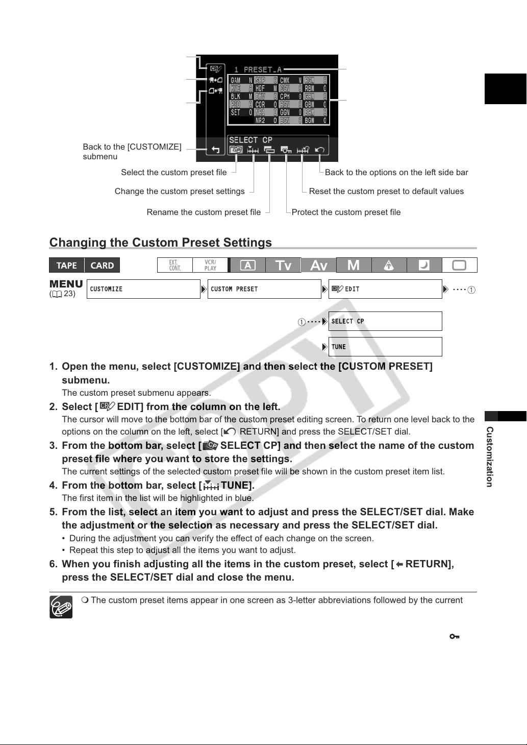
CUSTOMIZE CUSTOM PRESET EDIT ····
····
SELECT CP
TUNE
Enter the custom preset
editing screen
Save the custom preset file to
the memory card
Load a custom preset file
from the memory card
Back to the [CUSTOMIZE]
submenu
Select the custom preset file
File name of the currently
selected custom preset file
Overview of the contents of the
custom preset file
Back to the options on the left side bar
E
Change the custom preset settings
Rename the custom preset file
Reset the custom preset to default values
Protect the custom preset file
Changing the Custom Preset Settings
MENU
(23)
1. Open the menu, select [CUSTOMIZE] and then select the [CUSTOM PRESET]
2. Select [ EDIT] from the column on the left.
3. From the bottom bar, select [ SELECT CP] and then select the name of the custom
4. From the bottom bar, select [ TUNE].
5. From the list, select an item you want to adjust and press the SELECT/SET dial. Make
6. When you finish adjusting all the items in the custom preset, select [ RETURN],
submenu.
The custom preset submenu appears.
The cursor will move to the bottom bar of the custom preset editing screen. To return one level back to the
options on the column on the left, select [ RETURN] and press the SELECT/SET dial.
preset file where you want to store the settings.
The current settings of the selected custom preset file will be shown in the custom preset item list.
The first item in the list will be highlighted in blue.
the adjustment or the selection as necessary and press the SELECT/SET dial.
• During the adjustment you can verify the effect of each change on the screen.
• Repeat this step to adjust all the items you want to adjust.
press the SELECT/SET dial and close the menu.
Customization
The custom preset items appear in one screen as 3-letter abbreviations followed by the current
setting value. As you move between the items with the SELECT/SET dial, the full name of the
currently selected item and its current value will be displayed at the bottom of the screen.
A protected custom preset file cannot be changed. If you attempt to change a protected file, will
start flashing.
75
Page 76
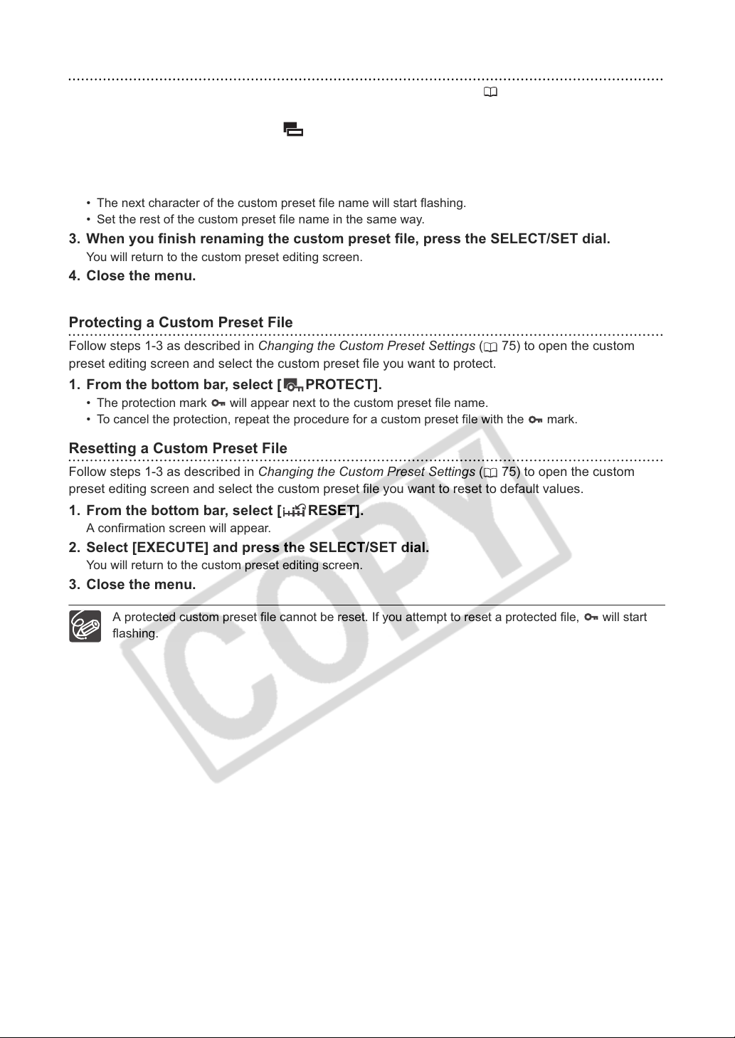
Renaming a Custom Preset File
Follow steps 1-3 as described in Changing the Custom Preset Settings ( 75) to open the custom
preset editing screen and select the custom preset file you want to rename.
1. From the bottom bar, select [ RENAME].
The first character of the custom preset file name will start flashing.
2. Turn the SELECT/SET dial to select a number, letter or punctuation mark and press
the dial.
• The next character of the custom preset file name will start flashing.
• Set the rest of the custom preset file name in the same way.
3. When you finish renaming the custom preset file, press the SELECT/SET dial.
You will return to the custom preset editing screen.
4. Close the menu.
Protecting a Custom Preset File
Follow steps 1-3 as described in Changing the Custom Preset Settings ( 75) to open the custom
preset editing screen and select the custom preset file you want to protect.
1. From the bottom bar, select [ PROTECT].
• The protection mark will appear next to the custom preset file name.
• To cancel the protection, repeat the procedure for a custom preset file with the mark.
Resetting a Custom Preset File
Follow steps 1-3 as described in Changing the Custom Preset Settings ( 75) to open the custom
preset editing screen and select the custom preset file you want to reset to default values.
1. From the bottom bar, select [ RESET].
A confirmation screen will appear.
2. Select [EXECUTE] and press the SELECT/SET dial.
You will return to the custom preset editing screen.
3. Close the menu.
76
A protected custom preset file cannot be reset. If you attempt to reset a protected file, will start
flashing.
Page 77
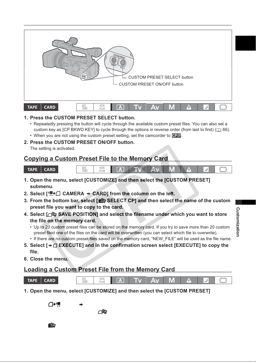
Activating the Custom Preset Settings
CUSTOM PRESET SELECT button
CUSTOM PRESET ON/OFF button
1. Press the CUSTOM PRESET SELECT button.
• Repeatedly pressing the button will cycle through the available custom preset files. You can also set a
custom key as [CP BKWD KEY] to cycle through the options in reverse order (from last to first) ( 66).
• When you are not using the custom preset setting, set the camcorder to .
2. Press the CUSTOM PRESET ON/OFF button.
The setting is activated.
Copying a Custom Preset File to the Memory Card
E
1. Open the menu, select [CUSTOMIZE] and then select the [CUSTOM PRESET]
submenu.
2. Select [ CAMERA CARD] from the column on the left.
3. From the bottom bar, select [ SELECT CP] and then select the name of the custom
preset file you want to copy to the card.
4. Select [ SAVE POSITION] and select the filename under which you want to store
the file on the memory card.
• Up to 20 custom preset files can be stored on the memory card. If you try to save more than 20 custom
preset filed one of the files on the card will be overwritten (you can select which file to overwrite).
• If there are no custom preset files saved on the memory card, “NEW_FILE” will be used as the file name.
5. Select [ EXECUTE] and in the confirmation screen select [EXECUTE] to copy the
file.
6. Close the menu.
Loading a Custom Preset File from the Memory Card
1. Open the menu, select [CUSTOMIZE] and then select the [CUSTOM PRESET]
submenu.
2. Select [ CARD CAMERA] from the column on the left.
3. From the bottom bar, select [ IMPORT] and then select the name of the custom
preset file you want to load to the camcorder.
4. Select [ SELECT POSITION] and select the preset number under which you want to
store the file in the camcorder.
Customization
77
Page 78
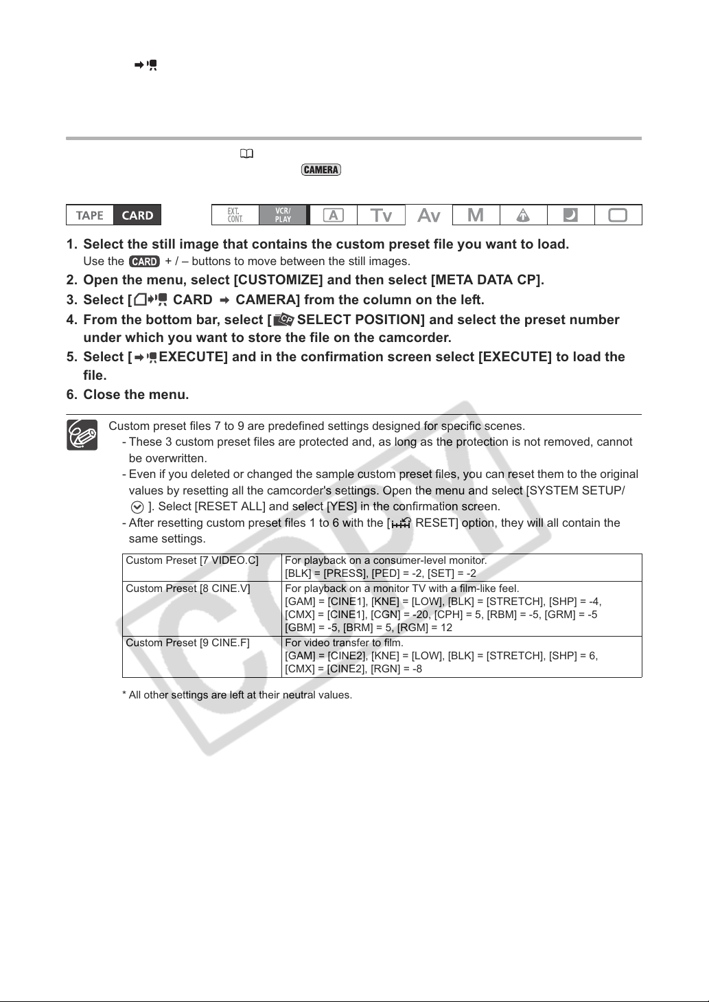
5. Select [ EXECUTE] and in the confirmation screen select [EXECUTE] to load the
file.
6. Close the menu.
Loading a Custom Preset File from a Still Image to the Camcorder
With the customized functions ( 79) you can select to save the custom preset settings currently in use
along with a still image of the recording in mode. This is very useful when you want to load the
custom preset file later by selecting the still image captured from a specific scene.
1. Select the still image that contains the custom preset file you want to load.
Use the + / – buttons to move between the still images.
2. Open the menu, select [CUSTOMIZE] and then select [META DATA CP].
3. Select [ CARD CAMERA] from the column on the left.
4. From the bottom bar, select [ SELECT POSITION] and select the preset number
under which you want to store the file on the camcorder.
5. Select [ EXECUTE] and in the confirmation screen select [EXECUTE] to load the
file.
6. Close the menu.
Custom preset files 7 to 9 are predefined settings designed for specific scenes.
- These 3 custom preset files are protected and, as long as the protection is not removed, cannot
be overwritten.
- Even if you deleted or changed the sample custom preset files, you can reset them to the original
values by resetting all the camcorder's settings. Open the menu and select [SYSTEM SETUP/
]. Select [RESET ALL] and select [YES] in the confirmation screen.
- After resetting custom preset files 1 to 6 with the [ RESET] option, they will all contain the
same settings.
Custom Preset [7 VIDEO.C] For playback on a consumer-level monitor.
Custom Preset [8 CINE.V] For playback on a monitor TV with a film-like feel.
Custom Preset [9 CINE.F] For video transfer to film.
[BLK] = [PRESS], [PED] = -2, [SET] = -2
[GAM] = [CINE1], [KNE] = [LOW], [BLK] = [STRETCH], [SHP] = -4,
[CMX] = [CINE1], [CGN] = -20, [CPH] = 5, [RBM] = -5, [GRM] = -5
[GBM] = -5, [BRM] = 5, [RGM] = 12
[GAM] = [CINE2], [KNE] = [LOW], [BLK] = [STRETCH], [SHP] = 6,
[CMX] = [CINE2], [RGN] = -8
78
* All other settings are left at their neutral values.
Page 79
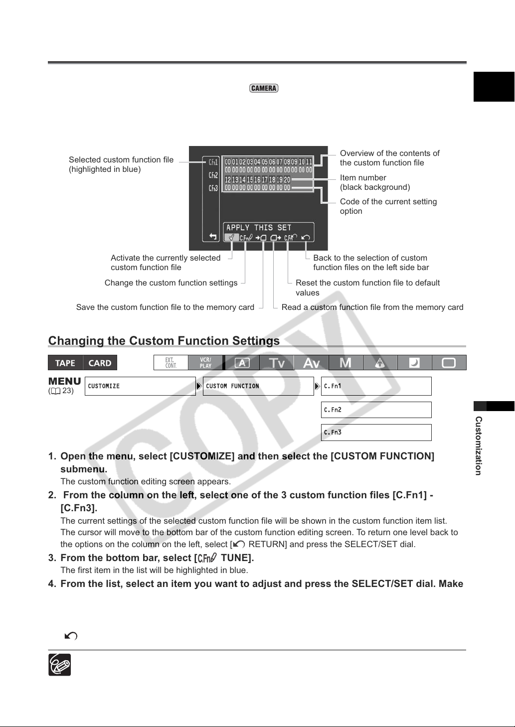
Using the Customized Functions
CUSTOMIZE CUSTOM FUNCTION C.Fn1
C.Fn2
C.Fn3
You can customize to your personal preferences many aspects of the operation of the camcorder, most
of them governing how the camcorder operates in mode. You can adjust up to 3 different custom
function files and save them on the camcorder or to a memory card. By just reading the custom function
file saved on the memory card with another XH G1/XH A1, you will instantly get a camcorder configured
to operate in the same familiar manner you prefer.
E
Selected custom function file
(highlighted in blue)
Activate the currently selected
custom function file
Change the custom function settings
Save the custom function file to the memory card Read a custom function file from the memory card
Reset the custom function file to default
values
Overview of the contents of
the custom function file
Item number
(black background)
Code of the current setting
option
Back to the selection of custom
function files on the left side bar
Changing the Custom Function Settings
MENU
(23)
Customization
1. Open the menu, select [CUSTOMIZE] and then select the [CUSTOM FUNCTION]
submenu.
The custom function editing screen appears.
2. From the column on the left, select one of the 3 custom function files [C.Fn1] -
[C.Fn3].
The current settings of the selected custom function file will be shown in the custom function item list.
The cursor will move to the bottom bar of the custom function editing screen. To return one level back to
the options on the column on the left, select [ RETURN] and press the SELECT/SET dial.
3. From the bottom bar, select [ TUNE].
The first item in the list will be highlighted in blue.
4. From the list, select an item you want to adjust and press the SELECT/SET dial. Make
the selection as necessary and press the SELECT/SET dial.
Repeat this step to adjust all the items you want to adjust.
5. When you finish adjusting all the items in the custom function file, select
[ RETURN], press the SELECT/SET dial and close the menu.
The custom function items appear in one screen represented only by the item number on the top
(numbers 00 - 20 with a black background), and the code of the current setting immediately under it.
79
Page 80
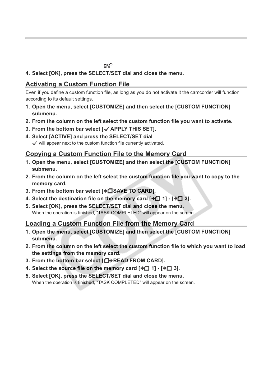
Resetting a Custom Function File
1. Open the menu, select [CUSTOMIZE] and then select the [CUSTOM FUNCTION]
submenu.
2. From the column on the left select the custom function file you want to reset.
3. From the bottom bar select [ RESET].
4. Select [OK], press the SELECT/SET dial and close the menu.
Activating a Custom Function File
Even if you define a custom function file, as long as you do not activate it the camcorder will function
according to its default settings.
1. Open the menu, select [CUSTOMIZE] and then select the [CUSTOM FUNCTION]
submenu.
2. From the column on the left select the custom function file you want to activate.
3. From the bottom bar select [ APPLY THIS SET].
4. Select [ACTIVE] and press the SELECT/SET dial
will appear next to the custom function file currently activated.
Copying a Custom Function File to the Memory Card
1. Open the menu, select [CUSTOMIZE] and then select the [CUSTOM FUNCTION]
submenu.
2. From the column on the left select the custom function file you want to copy to the
memory card.
3. From the bottom bar select [ SAVE TO CARD].
4. Select the destination file on the memory card [ 1] - [ 3].
5. Select [OK], press the SELECT/SET dial and close the menu.
When the operation is finished, "TASK COMPLETED" will appear on the screen.
Loading a Custom Function File from the Memory Card
1. Open the menu, select [CUSTOMIZE] and then select the [CUSTOM FUNCTION]
submenu.
2. From the column on the left select the custom function file to which you want to load
the settings from the memory card.
3. From the bottom bar select [ READ FROM CARD].
4. Select the source file on the memory card [ 1] - [ 3].
5. Select [OK], press the SELECT/SET dial and close the menu.
When the operation is finished, "TASK COMPLETED" will appear on the screen.
80
Page 81
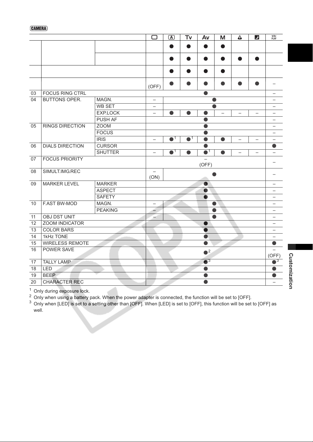
Availability of custom functions in each recording program/playback mode
Custom Function
00 SHCKLSS WB/GN WHITE BALANCE –
GAIN –
01 AE RESPONSE –
02 HIGH-SPEED ZOOM –
03 FOCUS RING CTRL –
04 BUTTONS OPER. MAGN. – –
WB SET – –
EXP.LOCK – – – – –
PUSH AF –
05 RINGS DIRECTION ZOOM –
FOCUS –
IRIS –
06 DIALS DIRECTION CURSOR
SHUTTER –
07 FOCUS PRIORITY –
08 SIMULT.IMG.REC –
09 MARKER LEVEL MARKER –
ASPECT –
SAFETY –
10 F.AST BW-MOD MAGN. – –
PEAKING – –
11 OBJ DST UNIT – –
12 ZOOM INDICATOR –
13 COLOR BARS –
14 1kHz TONE –
15 WIRELESS REMOTE
16 POWER SAVE
17 TALLY LAMP
18 LED
19 BEEP
20 CHARACTER REC –
1
Only during exposure lock.
2
Only when using a battery pack. When the power adapter is connected, the function will be set to [OFF].
3
Only when [LED] is set to a setting other than [OFF]. When [LED] is set to [OFF], this function will be set to [OFF] as
well.
(OFF)
(OFF)
(MID)
(OFF)
11
11
(OFF)
(ON)
2
33
–
(OFF)–(OFF)
–
(MID)–(MID)
–––
–––
–
–
–
–
–
–
–
(OFF)
E
Customization
81
Page 82
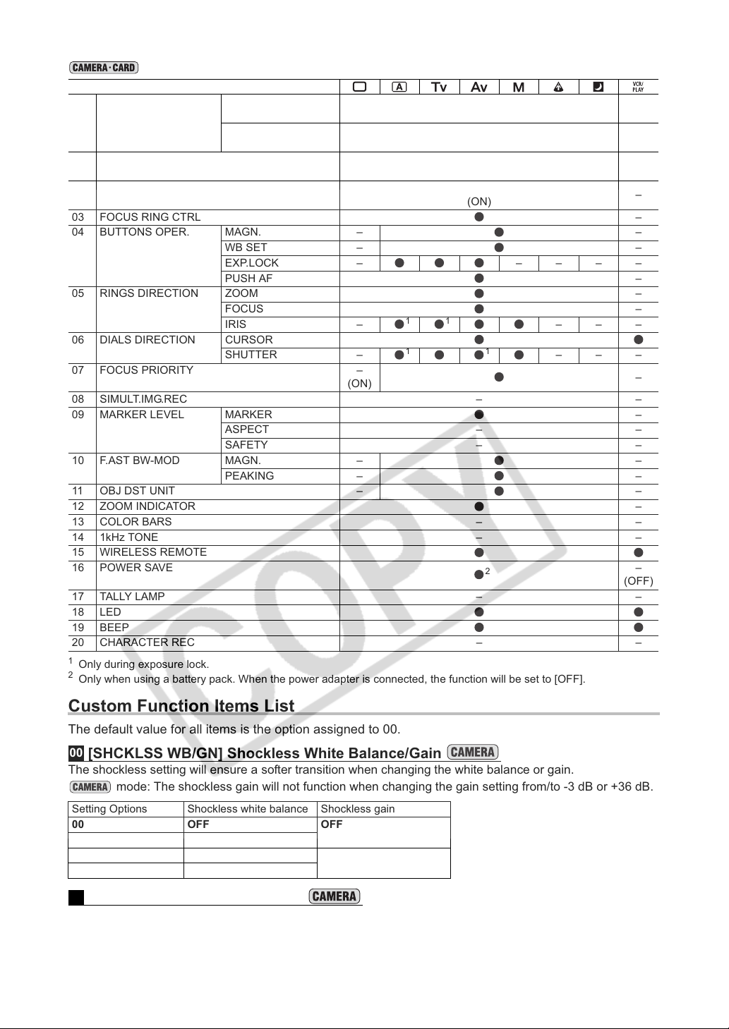
Availability of custom functions in each recording program/playback mode
Custom Function
00 SHCKLSS WB/GN WHITE BALANCE –
GAIN –
01 AE RESPONSE –
02 HIGH-SPEED ZOOM –
03 FOCUS RING CTRL –
04 BUTTONS OPER. MAGN. – –
WB SET – –
EXP.LOCK – – – – –
PUSH AF –
05 RINGS DIRECTION ZOOM –
FOCUS –
IRIS –
06 DIALS DIRECTION CURSOR
SHUTTER –
07 FOCUS PRIORITY –
08 SIMULT.IMG.REC – –
09 MARKER LEVEL MARKER –
ASPECT – –
SAFETY – –
10 F.AST BW-MOD MAGN. – –
PEAKING – –
11 OBJ DST UNIT – –
12 ZOOM INDICATOR –
13 COLOR BARS – –
14 1kHz TONE – –
15 WIRELESS REMOTE
16 POWER SAVE
17 TALLY LAMP – –
18 LED
19 BEEP
20 CHARACTER REC – –
1
Only during exposure lock.
2
Only when using a battery pack. When the power adapter is connected, the function will be set to [OFF].
(ON)
11
11
(OFF)
(OFF)
(MID)
(ON)
–––
–––
2
–
–
–
–
–
–
(OFF)
Custom Function Items List
The default value for all items is the option assigned to 00.
00
[SHCKLSS WB/GN] Shockless White Balance/Gain
The shockless setting will ensure a softer transition when changing the white balance or gain.
mode: The shockless gain will not function when changing the gain setting from/to -3 dB or +36 dB.
Setting Options Shockless white balance Shockless gain
00 OFF OFF
01 ON
02 OFF ON
03 ON
01
AE Response [AE RESPONSE]
Selects the camcorder’s response when you change the automatic exposure setting.
Setting Options: 00 – MIDDLE, 01 – HIGH, 02 – LOW.
82
Page 83
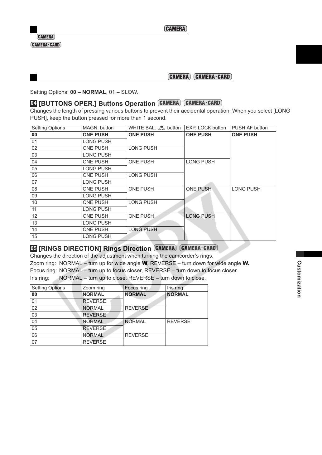
02
[HIGH-SPEED ZOOM] High-speed Zoom
In mode, makes the zoom operation at the constant zoom speeds 14 - 16 even faster (in
mode the default is [ON] and cannot be changed).
• When set to [ON], if you operate the zoom ring very quickly the zoom response may lag slightly.
• At the fastest zoom speed settings the autofocus may not work correctly.
Setting Options: 00 – OFF, 01 – ON.
03
[FOCUS RING CTRL] Focus Ring Control
Selects the sensitivity of the response when operating the FOCUS ring.
Setting Options: 00 – NORMAL, 01 – SLOW.
04
[BUTTONS OPER.] Buttons Operation
Changes the length of pressing various buttons to prevent their accidental operation. When you select [LONG
PUSH], keep the button pressed for more than 1 second.
Setting Options MAGN. button WHITE BAL. button EXP. LOCK button PUSH AF button
00 ONE PUSH ONE PUSH ONE PUSH ONE PUSH
01 LONG PUSH
02 ONE PUSH LONG PUSH
03 LONG PUSH
04 ONE PUSH ONE PUSH LONG PUSH
05 LONG PUSH
06 ONE PUSH LONG PUSH
07 LONG PUSH
08 ONE PUSH ONE PUSH ONE PUSH LONG PUSH
09 LONG PUSH
10 ONE PUSH LONG PUSH
11 LO NG PU SH
12 ONE PUSH ONE PUSH LONG PUSH
13 LONG PUSH
14 ONE PUSH LONG PUSH
15 LONG PUSH
E
05
[RINGS DIRECTION] Rings Direction
Changes the direction of the adjustment when turning the camcorder’s rings.
Zoom ring: NORMAL – turn up for wide angle W, REVERSE – turn down for wide angle W.
Focus ring: NORMAL – turn up to focus closer, REVERSE – turn down to focus closer.
Iris ring: NORMAL – turn up to close, REVERSE – turn down to close.
Setting Options Zoom ring Focus ring Iris ring
00 NORMAL NORMAL NORMAL
01 REVERSE
02 NORMAL REVERSE
03 REVERSE
04 NORMAL NORMAL REVERSE
05 REVERSE
06 NORMAL REVERSE
07 REVERSE
Customization
83
Page 84
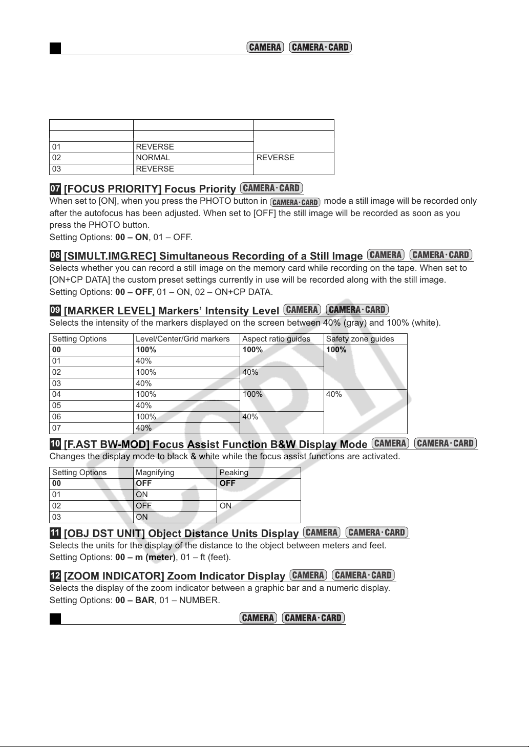
06
[DIALS DIRECTION] Dials Direction
Changes the direction of the adjustment when operating the shutter dial and the SELECT/SET dial when it
serves as a cursor (for example, while selecting setting options in the menu screens or in the index screen).
SELECT/SET dial ([CURSOR]): NORMAL – turn up to move left, REVERSE – turn down to move left.
SHUTTER dial: NORMAL – turn up for a faster shutter speed, REVERSE – turn down for a
faster shutter speed.
Setting Options SELECT/SET dial ([CURSOR]) SHUTTER dial
00 NORMAL NORMAL
01 REVERSE
02 NORMAL REVERSE
03 REVERSE
07
[FOCUS PRIORITY] Focus Priority
When set to [ON], when you press the PHOTO button in mode a still image will be recorded only
after the autofocus has been adjusted. When set to [OFF] the still image will be recorded as soon as you
press the PHOTO button.
Setting Options: 00 – ON, 01 – OFF.
08
[SIMULT.IMG.REC] Simultaneous Recording of a Still Image
Selects whether you can record a still image on the memory card while recording on the tape. When set to
[ON+CP DATA] the custom preset settings currently in use will be recorded along with the still image.
Setting Options: 00 – OFF, 01 – ON, 02 – ON+CP DATA.
09
[MARKER LEVEL] Markers’ Intensity Level
Selects the intensity of the markers displayed on the screen between 40% (gray) and 100% (white).
Setting Options Level/Center/Grid markers Aspect ratio guides Safety zone guides
00 100% 100% 100%
01 40%
02 100% 40%
03 40%
04 100% 100% 40%
05 40%
06 100% 40%
07 40%
10
[F.AST BW-MOD] Focus Assist Function B&W Display Mode
Changes the display mode to black & white while the focus assist functions are activated.
Setting Options Magnifying Peaking
00 OFF OFF
01 ON
02 OFF ON
03 ON
11
[OBJ DST UNIT] Object Distance Units Display
Selects the units for the display of the distance to the object between meters and feet.
Setting Options: 00 – m (meter), 01 – ft (feet).
12
[ZOOM INDICATOR] Zoom Indicator Display
Selects the display of the zoom indicator between a graphic bar and a numeric display.
Setting Options: 00 – BAR, 01 – NUMBER.
13
[COLOR BARS] Color Bars Signal
Selects the type of signal to use to produce the color bars: EBU color bars (type 1) or SMPTE color bars
(type 2).
Setting Options: 00 – TYPE 1, 01 – TYPE 2.
84
Page 85
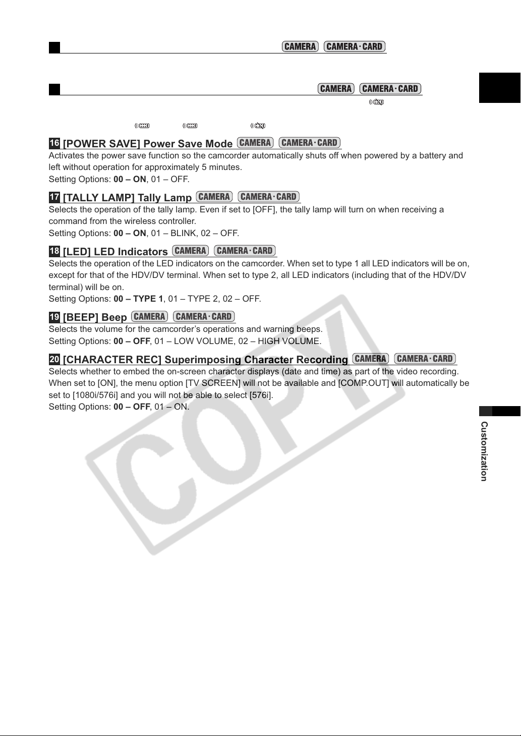
14
[1kHz TONE] 1 kHz Reference Audio Signal
Selects the strength of the audio signal.
Setting Options: 00 – OFF, 01 – -12dB, 02 – -20dB.
15
[WIRELESS REMOTE] Wireless Remote Controller
Selects the remote sensor mode that the camcorder will accept. When set to [OFF ] the camcorder will
not accept commands from wireless controllers.
Setting Options: 00 – 1, 01 – 2, 02 – OFF .
16
[POWER SAVE] Power Save Mode
Activates the power save function so the camcorder automatically shuts off when powered by a battery and
left without operation for approximately 5 minutes.
Setting Options: 00 – ON, 01 – OFF.
17
[TALLY LAMP] Ta l l y L a m p
Selects the operation of the tally lamp. Even if set to [OFF], the tally lamp will turn on when receiving a
command from the wireless controller.
Setting Options: 00 – ON, 01 – BLINK, 02 – OFF.
18
[LED] LED Indicators
Selects the operation of the LED indicators on the camcorder. When set to type 1 all LED indicators will be on,
except for that of the HDV/DV terminal. When set to type 2, all LED indicators (including that of the HDV/DV
terminal) will be on.
Setting Options: 00 – TYPE 1, 01 – TYPE 2, 02 – OFF.
19
[BEEP] Beep
Selects the volume for the camcorder’s operations and warning beeps.
Setting Options: 00 – OFF, 01 – LOW VOLUME, 02 – HIGH VOLUME.
20
[CHARACTER REC] Superimposing Character Recording
Selects whether to embed the on-screen character displays (date and time) as part of the video recording.
When set to [ON], the menu option [TV SCREEN] will not be available and [COMP.OUT] will automatically be
set to [1080i/576i] and you will not be able to select [576i].
Setting Options: 00 – OFF, 01 – ON.
E
Customization
85
Page 86
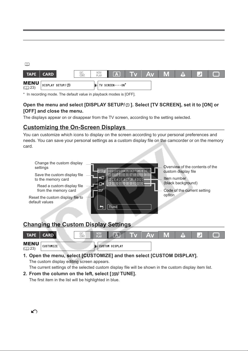
Customizing the On-Screen Displays
DISPLAY SETUP/ TV SCREEN
ON
*
CUSTOMIZE CUSTOM DISPLAY
Hiding/Showing the Displays on the TV Screen
When you connect a TV for recording, you can select to hide the camcorder displays on the TV screen.
For playback, you can show the camcorder displays on the TV screen.
To activate the on-screen displays at the level that you customized, repeatedly press the DISP. button
( 27).
MENU
(23)
* In recording mode. The default value in playback modes is [OFF].
••••
Open the menu and select [DISPLAY SETUP/ ]. Select [TV SCREEN], set it to [ON] or
[OFF] and close the menu.
The displays appear on or disappear from the TV screen, according to the setting selected.
Customizing the On-Screen Displays
You can customize which icons to display on the screen according to your personal preferences and
needs. You can save your personal settings as a custom display file on the camcorder or on the memory
card.
Change the custom display
settings
Save the custom display file
to the memory card
Read a custom display file
from the memory card
Reset the custom display file to
default values
Overview of the contents of the
custom display file
Item number
(black background)
Code of the current setting
option
Changing the Custom Display Settings
MENU
(23)
1. Open the menu, select [CUSTOMIZE] and then select [CUSTOM DISPLAY].
2. From the column on the left, select [ TUNE].
3. From the list, select an item you want to adjust and press the SELECT/SET dial. Make
4. When you finish adjusting all the items in the custom display file, select
5. Repeatedly press the DISP. button to select the display level you customized.
86
The custom display editing screen appears.
The current settings of the selected custom display file will be shown in the custom display item list.
The first item in the list will be highlighted in blue.
the selection as necessary and press the SELECT/SET dial.
Repeat this step to adjust all the items you want to adjust.
[ RETURN], press the SELECT/SET dial and close the menu.
Page 87
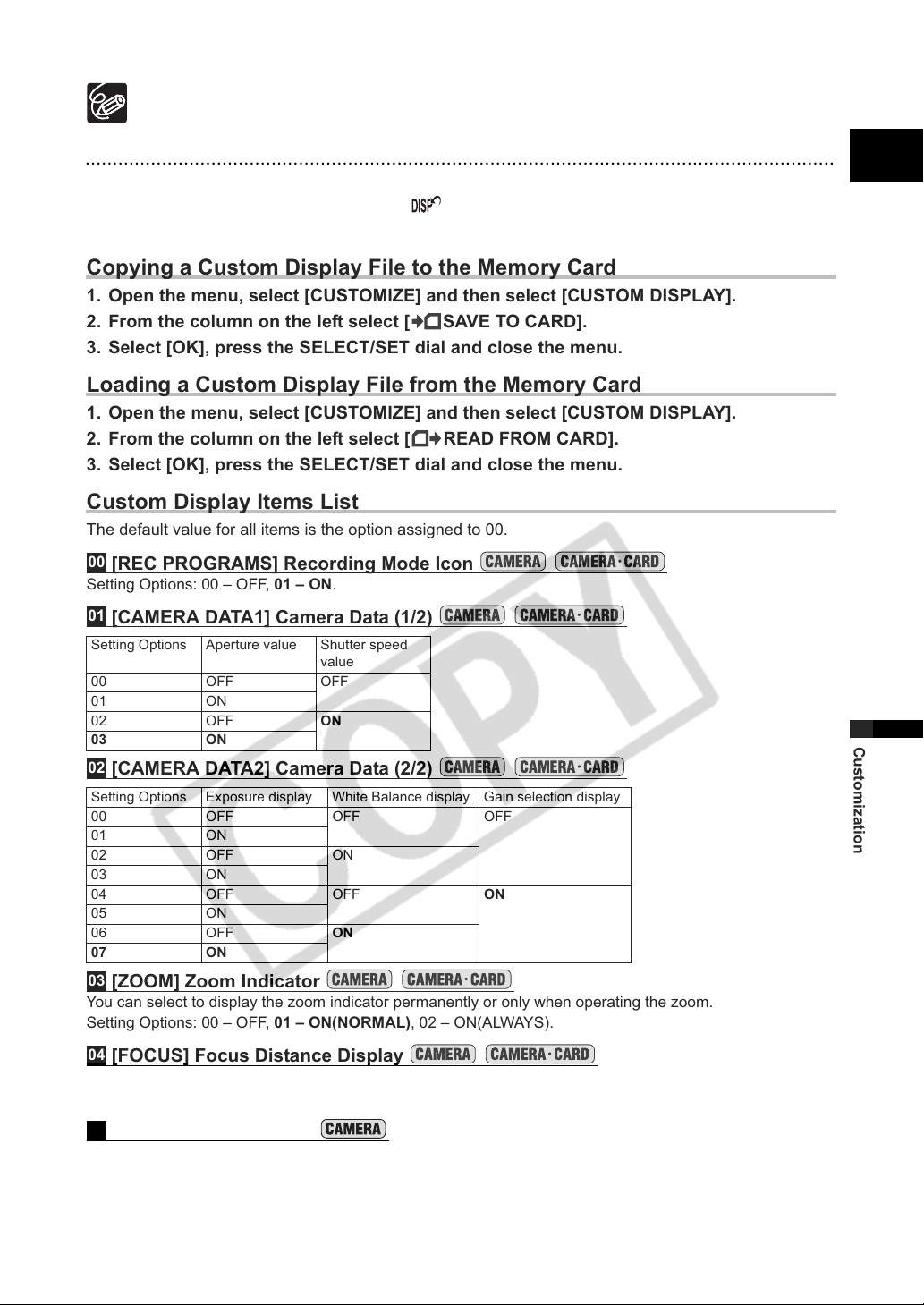
The custom display items appear in one screen represented only by the item number on the top
(numbers 00 – 21 with a black background), and the code of the current setting immediately under it.
Resetting a Custom Display File
1. Open the menu, select [CUSTOMIZE] and then select [CUSTOM DISPLAY].
2. From the column on the left select [ RESET].
3. Select [OK], press the SELECT/SET dial and close the menu.
Copying a Custom Display File to the Memory Card
1. Open the menu, select [CUSTOMIZE] and then select [CUSTOM DISPLAY].
2. From the column on the left select [ SAVE TO CARD].
3. Select [OK], press the SELECT/SET dial and close the menu.
Loading a Custom Display File from the Memory Card
1. Open the menu, select [CUSTOMIZE] and then select [CUSTOM DISPLAY].
2. From the column on the left select [ READ FROM CARD].
3. Select [OK], press the SELECT/SET dial and close the menu.
Custom Display Items List
The default value for all items is the option assigned to 00.
00
[REC PROGRAMS] Recording Mode Icon
Setting Options: 00 – OFF, 01 – ON.
01
[CAMERA DATA1] Camera Data (1/2)
Setting Options Aperture value Shutter speed
00 OFF OFF
01 ON
02 OFF ON
03 ON
02
[CAMERA DATA2] Camera Data (2/2)
Setting Options Exposure display White Balance display Gain selection display
00 OFF OFF OFF
01 ON
02 OFF ON
03 ON
04 OFF OFF ON
05 ON
06 OFF ON
07 ON
03
[ZOOM] Zoom Indicator
You can select to display the zoom indicator permanently or only when operating the zoom.
Setting Options: 00 – OFF, 01 – ON(NORMAL), 02 – ON(ALWAYS).
value
E
Customization
04
[FOCUS] Focus Distance Display
You can select to display the focus distance indication permanently or only when operating the focus.
Setting Options: 00 – OFF, 01 – ON(NORMAL), 02 – ON(ALWAYS)
05
[ND] ND Filter displays
Setting Options: 00 – OFF, 01 – ON.
87
Page 88
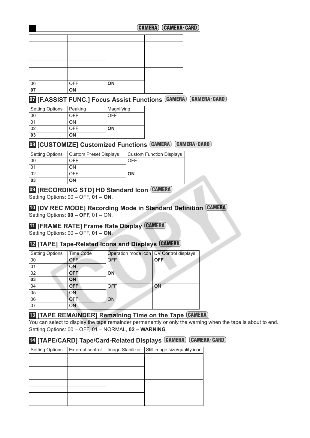
06
[IMAGE EFFECTS] Image Effects
Setting Options Skin detail Sky detail Color correction
00 OFF OFF OFF
01 ON
02 OFF ON
03 ON
04 OFF OFF ON
05 ON
06 OFF ON
07 ON
07
[F.ASSIST FUNC.] Focus Assist Functions
Setting Options Peaking Magnifying
00 OFF OFF
01 ON
02 OFF ON
03 ON
08
[CUSTOMIZE] Customized Functions
Setting Options Custom Preset Displays Custom Function Displays
00 OFF OFF
01 ON
02 OFF ON
03 ON
09
[RECORDING STD] HD Standard Icon
Setting Options: 00 – OFF, 01 – ON.
10
[DV REC MODE] Recording Mode in Standard Definition
Setting Options: 00 – OFF, 01 – ON.
11
[FRAME RATE] Frame Rate Display
Setting Options: 00 – OFF, 01 – ON.
12
[TAPE] Tape-Related Icons and Displays
Setting Options Time Code Operation mode icon DV Control displays
00 OFF OFF OFF
01 ON
02 OFF ON
03 ON
04 OFF OFF ON
05 ON
06 OFF ON
07 ON
13
[TAPE REMAINDER] Remaining Time on the Tape
You can select to display the tape remainder permanently or only the warning when the tape is about to end.
Setting Options: 00 – OFF, 01 – NORMAL, 02 – WARNING.
14
[TAPE/CARD] Tape/Card-Related Displays
Setting Options External control Image Stabilizer Still image size/quality icon
00 OFF OFF OFF
01 ON
02 OFF ON
03 ON
04 OFF OFF ON
05 ON
06 OFF ON
07 ON
88
Page 89
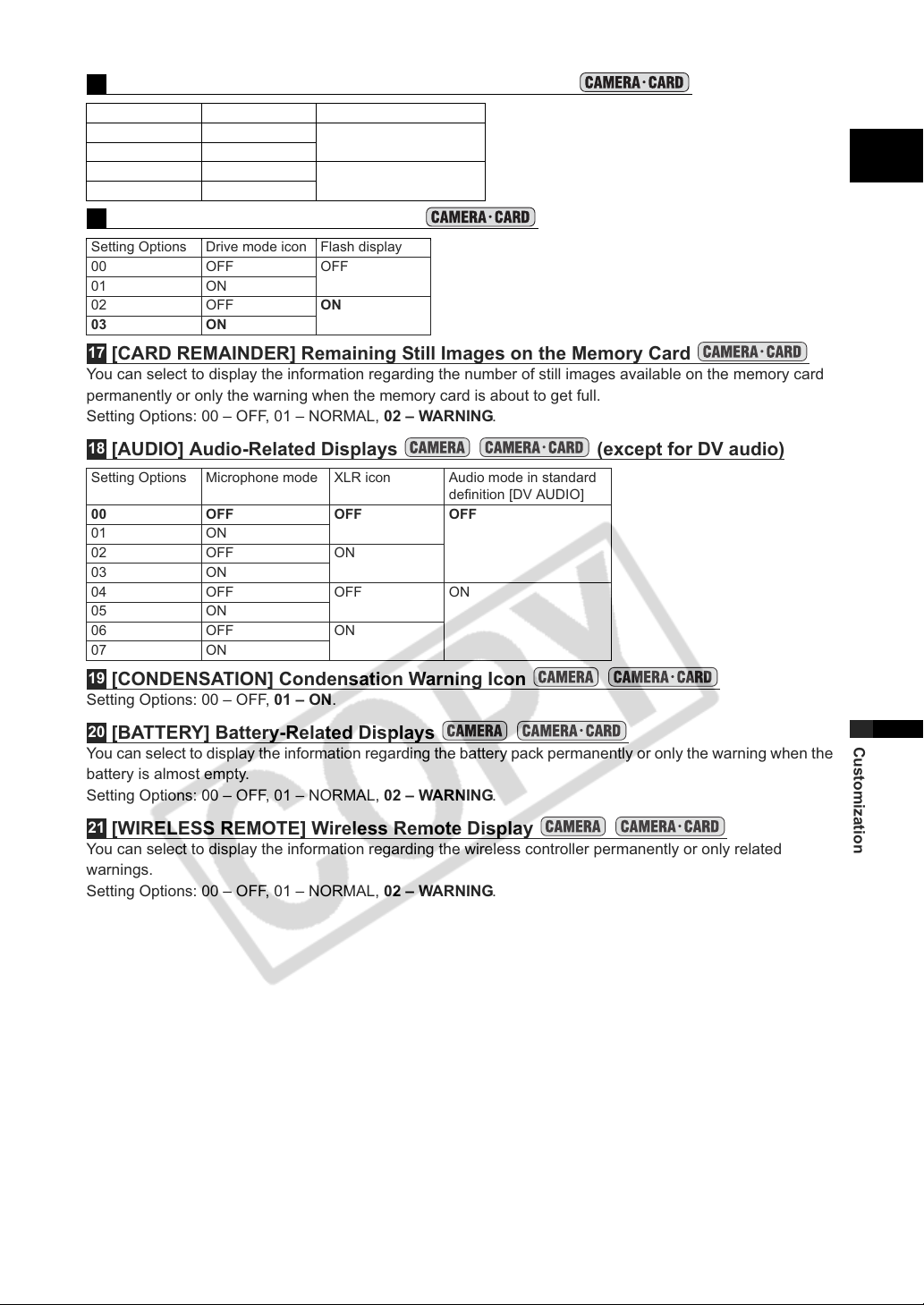
15
[LIGHT METERING] Light Metering-Related Displays
Setting Options SPOT AE point Light metering mode icon
00 OFF OFF
01 ON
02 OFF ON
03 ON
16
[CARD] Still Images-Related Icons
Setting Options Drive mode icon Flash display
00 OFF OFF
01 ON
02 OFF ON
03 ON
17
[CARD REMAINDER] Remaining Still Images on the Memory Card
You can select to display the information regarding the number of still images available on the memory card
permanently or only the warning when the memory card is about to get full.
Setting Options: 00 – OFF, 01 – NORMAL, 02 – WARNING.
18
[AUDIO] Audio-Related Displays (except for DV audio)
Setting Options Microphone mode XLR icon Audio mode in standard
00 OFF OFF OFF
01 ON
02 OFF ON
03 ON
04 OFF OFF ON
05 ON
06 OFF ON
07 ON
19
[CONDENSATION] Condensation Warning Icon
Setting Options: 00 – OFF, 01 – ON.
definition [DV AUDIO]
E
20
[BATTERY] Battery-Related Displays
You can select to display the information regarding the battery pack permanently or only the warning when the
battery is almost empty.
Setting Options: 00 – OFF, 01 – NORMAL, 02 – WARNING.
21
[WIRELESS REMOTE] Wireless Remote Display
You can select to display the information regarding the wireless controller permanently or only related
warnings.
Setting Options: 00 – OFF, 01 – NORMAL, 02 – WARNING.
89
Customization
Page 90
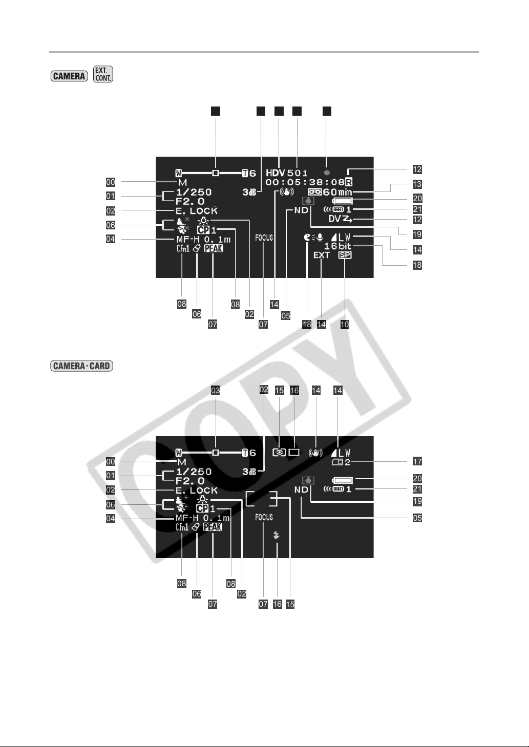
Location of the Custom Displays
/
00
01
02
06
04
08
03 02 09 11
06
08
02
03 1615
07
02
12
12
13
20
21
12
19
14
18
14
05
10141807
14 14
90
00
01
02
06
04
08
06
07
08
02
07
16
17
20
21
19
05
15
Page 91
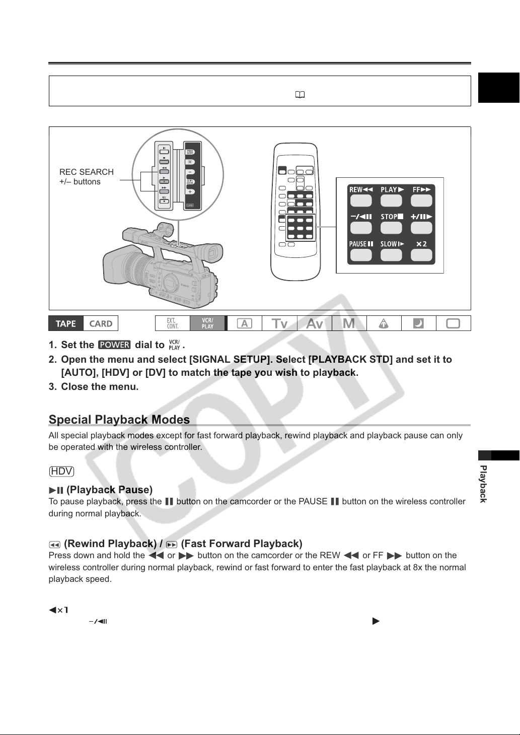
Playback
Playing Back a Tape
If the playback picture is distorted, clean the video heads using a Canon Video Head Cleaning Cassette or
a commercially available digital video head-cleaning cassette ( 144).
Select a playback standard according to the tape you wish to play back.
REC SEARCH
+/– buttons
1. Set the dial to .
2. Open the menu and select [SIGNAL SETUP]. Select [PLAYBACK STD] and set it to
[AUTO], [HDV] or [DV] to match the tape you wish to playback.
3. Close the menu.
E
Special Playback Modes
All special playback modes except for fast forward playback, rewind playback and playback pause can only
be operated with the wireless controller.
HDV
(Playback Pause)
To pause playback, press the button on the camcorder or the PAUSE button on the wireless controller
during normal playback.
(Rewind Playback) / (Fast Forward Playback)
Press down and hold the or button on the camcorder or the REW or FF button on the
wireless controller during normal playback, rewind or fast forward to enter the fast playback at 8x the normal
playback speed.
(Reverse Playback)
Press the button on the wireless controller during normal playback. Press the (play) button to return
to normal playback.
91
Playback
Page 92
(Frame Advance)
Plays back frame-by-frame. Repeatedly press the button on the wireless controller during playback
pause. Hold the button pressed down to enter the continuous frame advance playback.
(Slow Forward)
Plays back at about 1/3 normal speed. Press the SLOW button on the wireless controller during normal or
reverse playback. Press the (play) button to return to normal playback.
DV
(Playback Pause)
To pause playback, press the button on the camcorder or the PAUSE button on the wireless controller
during normal playback.
(Rewind Playback) / (Fast Forward Playback)
Plays back the tape at 11.5 times normal speed (forward or reverse). Press down and hold the or
button on the camcorder or the REW or FF button on the wireless controller during normal
playback, rewind or fast forward to enter the fast playback.
(Frame Reverse) / (Frame Advance)
Plays back frame-by-frame. Press the or button on the wireless controller repeatedly during
playback pause. Hold the button pressed down to enter the continuous frame advance/reverse playback.
(Slow Reverse) / (Slow Forward)
Plays back at about 1/3 normal speed. Press the SLOW button on the wireless controller during normal or
reverse playback. Press the (play) button to return to normal playback.
(Reverse Playback)
Press the button on the wireless controller during normal playback. Press the (play) button to return
to normal playback.
x2 (Reverse x2 Playback) / x2 (Forward x2 Playback)
Plays back at 2 times normal speed. Press the button on the wireless controller during normal or reverse
playback. Press the (play) button to return to normal playback.
The sound will be muted during special playback.
The picture may become distorted during some special playback modes.
The camcorder stops the tape automatically after 4 minutes 30 seconds in playback pause mode to
protect the tape and video heads.
In fast forward playback, rewind playback and reverse playback of a tape recorded in HDV mode,
the picture may be distorted.
The picture may be slightly distorted at the switch point between recordings in HDV and DV
standards on the tape.
92
Page 93
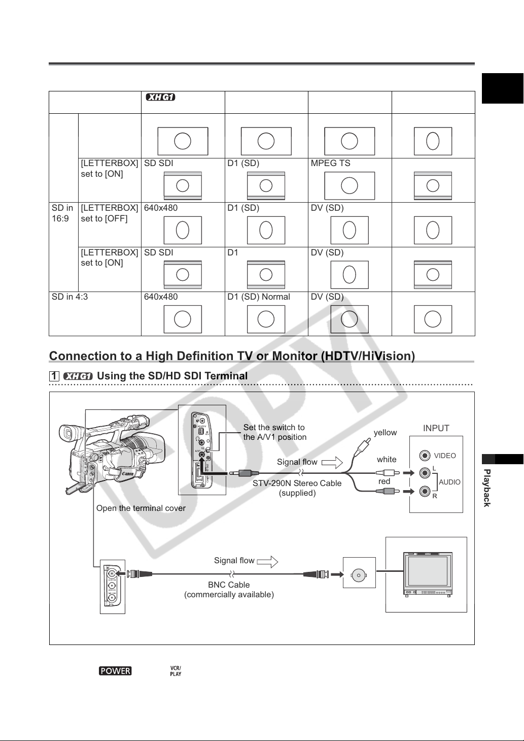
Connecting to a Monitor/TV
R
L
The different recording modes and the corresponding output terminals are given in the table below:
HD [LETTERBOX]
set to [OFF]
HD/SD SDI
Te rm i na l
1920x1080 D3 (1440x1080) MPEG TS
COMPONENT
OUT Terminal
HDV/DV
Te rm i na l
Video
Te rm in al s
E
[LETTERBOX]
set to [ON]
SD in
[LETTERBOX]
16:9
set to [OFF]
[LETTERBOX]
set to [ON]
SD in 4:3 640x480 D1 (SD) Normal DV (SD)
SD SDI D1 (SD) MPEG TS
640x480 D1 (SD) DV (SD)
SD SDI D1 DV (SD)
Connection to a High Definition TV or Monitor (HDTV/HiVision)
1
Using the SD/HD SDI Terminal
Open the terminal cover
Set the switch to
the A/V1 position
Signal flow
STV-290N Stereo Cable
(supplied)
yellow
white
red
INPUT
VIDEO
AUDIO
Playback
Signal flow
BNC Cable
(commercially available)
The audio and time code are embedded along
with the video signal output.
Activate the HD/SD SDI output and select the appropriate video output option (HD or SD).
1. Set the dial to .
93
Page 94
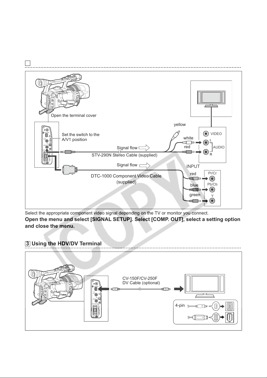
2. Open the menu and select [SIGNAL SETUP]. Select [SDI OUTPUT] and set it to [ON].
R
L
3. From the same [SIGNAL SETUP] submenu select [SDI SPEC.]. Select [AUTO] or
[SD LOCKED] to match the video output you wish to use.
4. Close the menu.
Using the COMPONENT OUT Terminal
2
Open the terminal cover
yellow
Set the switch to the
A/V1 position
STV-290N Stereo Cable (supplied)
DTC-1000 Component Video Cable
Signal flow
Signal flow
(supplied)
white
red
INPUT
red
blue
green
VIDEO
AUDIO
Pr/Cr
Pb/Cb
Y
Select the appropriate component video signal depending on the TV or monitor you connect.
Open the menu and select [SIGNAL SETUP]. Select [COMP. OUT], select a setting option
and close the menu.
Using the HDV/DV Terminal
3
CV-150F/CV-250F
DV Cable (optional)
4-pin
Open the terminal cover
6-pin
• When connecting the camcorder to a monitor TV that supports DV, you may need to carry out a procedure
on the TV to recognize the camera. Refer to the instruction manual of the TV or monitor.
94
Page 95
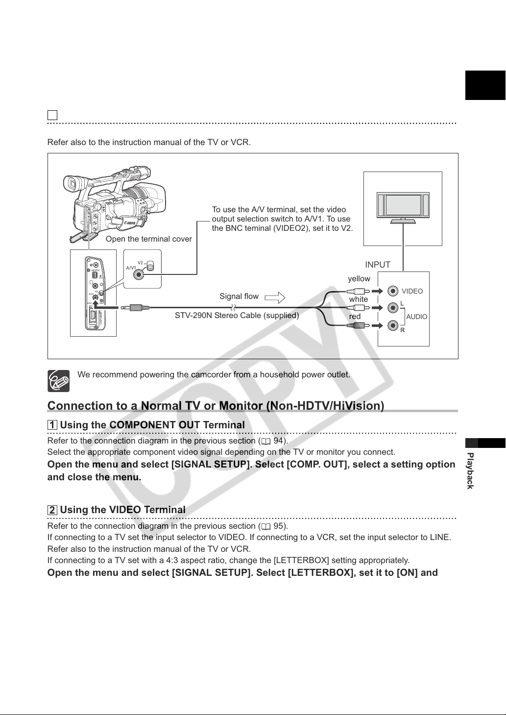
• If necessary, turn on the DV conversion and select whether to convert a tape recorded in HD to SD with the
R
L
following procedure.
Open the menu and select [SIGNAL SETUP]. Select [HD DOWN-CONV], select a setting
option and close the menu.
Using the VIDEO Terminal
4
If connecting to a TV, set the input selector to VIDEO. If connecting to a VCR, set the input selector to LINE.
Refer also to the instruction manual of the TV or VCR.
To use the A/V terminal, set the video
output selection switch to A/V1. To use
the BNC teminal (VIDEO2), set it to V2.
Open the terminal cover
INPUT
yellow
Signal flow
STV-290N Stereo Cable (supplied)
white
red
VIDEO
AUDIO
E
We recommend powering the camcorder from a household power outlet.
Connection to a Normal TV or Monitor (Non-HDTV/HiVision)
Using the COMPONENT OUT Terminal
1
Refer to the connection diagram in the previous section ( 94).
Select the appropriate component video signal depending on the TV or monitor you connect.
Open the menu and select [SIGNAL SETUP]. Select [COMP. OUT], select a setting option
and close the menu.
Using the VIDEO Terminal
2
Refer to the connection diagram in the previous section ( 95).
If connecting to a TV set the input selector to VIDEO. If connecting to a VCR, set the input selector to LINE.
Refer also to the instruction manual of the TV or VCR.
If connecting to a TV set with a 4:3 aspect ratio, change the [LETTERBOX] setting appropriately.
Open the menu and select [SIGNAL SETUP]. Select [LETTERBOX], set it to [ON] and
close the menu.
Playback
95
Page 96
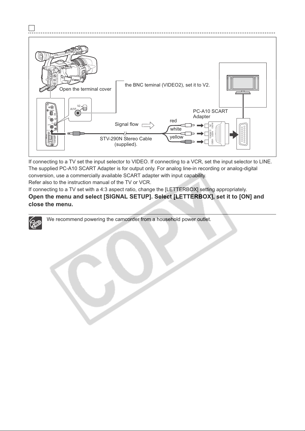
Using the SCART Adapter
3
To use the A/V terminal, set the video
output selection switch to A/V1. To use
Open the terminal cover
the BNC teminal (VIDEO2), set it to V2.
PC-A10 SCART
Adapter
(R)
(L/MONO)
AUDIO
AUDIO
VIDEO
Signal flow
STV-290N Stereo Cable
red
white
yellow
(supplied).
If connecting to a TV set the input selector to VIDEO. If connecting to a VCR, set the input selector to LINE.
The supplied PC-A10 SCART Adapter is for output only. For analog line-in recording or analog-digital
conversion, use a commercially available SCART adapter with input capability.
Refer also to the instruction manual of the TV or VCR.
If connecting to a TV set with a 4:3 aspect ratio, change the [LETTERBOX] setting appropriately.
Open the menu and select [SIGNAL SETUP]. Select [LETTERBOX], set it to [ON] and
close the menu.
We recommend powering the camcorder from a household power outlet.
96
Page 97
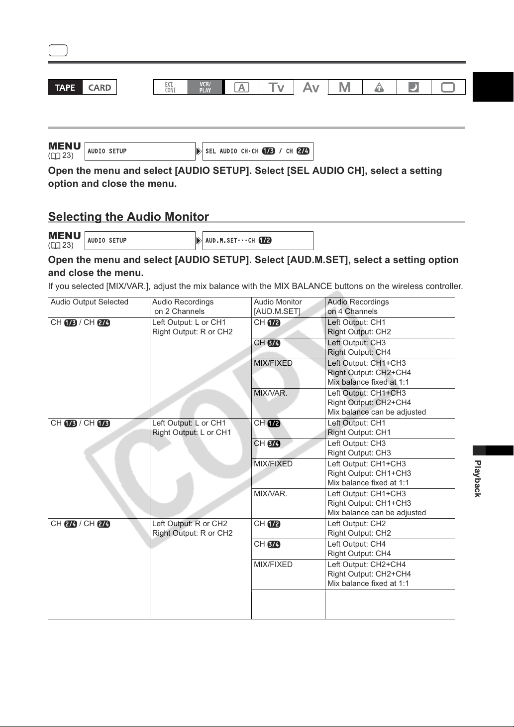
AUDIO SETUP SEL AUDIO CH•CH / CH
AUDIO SETUP AUD.M.SET
CH
SD
1/3 2/4
1/2
1/3 2/4 1/2
3/4
1/3 1/3 1/2
3/4
2/4 2/4 1/2
3/4
Audio Output
Selecting the Audio
E
MENU
(23)
Open the menu and select [AUDIO SETUP]. Select [SEL AUDIO CH], select a setting
option and close the menu.
Selecting the Audio Monitor
MENU
(23)
Open the menu and select [AUDIO SETUP]. Select [AUD.M.SET], select a setting option
and close the menu.
If you selected [MIX/VAR.], adjust the mix balance with the MIX BALANCE buttons on the wireless controller.
Audio Output Selected Audio Recordings
CH / CH Left Output: L or CH1
CH / CH Left Output: L or CH1
CH / CH Left Output: R or CH2
on 2 Channels
Right Output: R or CH2
Right Output: L or CH1
Right Output: R or CH2
•••
Audio Monitor
[AUD.M.SET]
CH Left Output: CH1
CH Left Output: CH3
MIX/FIXED Left Output: CH1+CH3
MIX/VAR. Left Output: CH1+CH3
CH Left Output: CH1
CH Left Output: CH3
MIX/FIXED Left Output: CH1+CH3
MIX/VAR. Left Output: CH1+CH3
CH Left Output: CH2
CH Left Output: CH4
MIX/FIXED Left Output: CH2+CH4
MIX/VAR. Left Output: CH2+CH4
Audio Recordings
on 4 Channels
Right Output: CH2
Right Output: CH4
Right Output: CH2+CH4
Mix balance fixed at 1:1
Right Output: CH2+CH4
Mix balance can be adjusted
Right Output: CH1
Right Output: CH3
Right Output: CH1+CH3
Mix balance fixed at 1:1
Right Output: CH1+CH3
Mix balance can be adjusted
Right Output: CH2
Right Output: CH4
Right Output: CH2+CH4
Mix balance fixed at 1:1
Right Output: CH2+CH4
Mix balance can be adjusted
Playback
97
Page 98
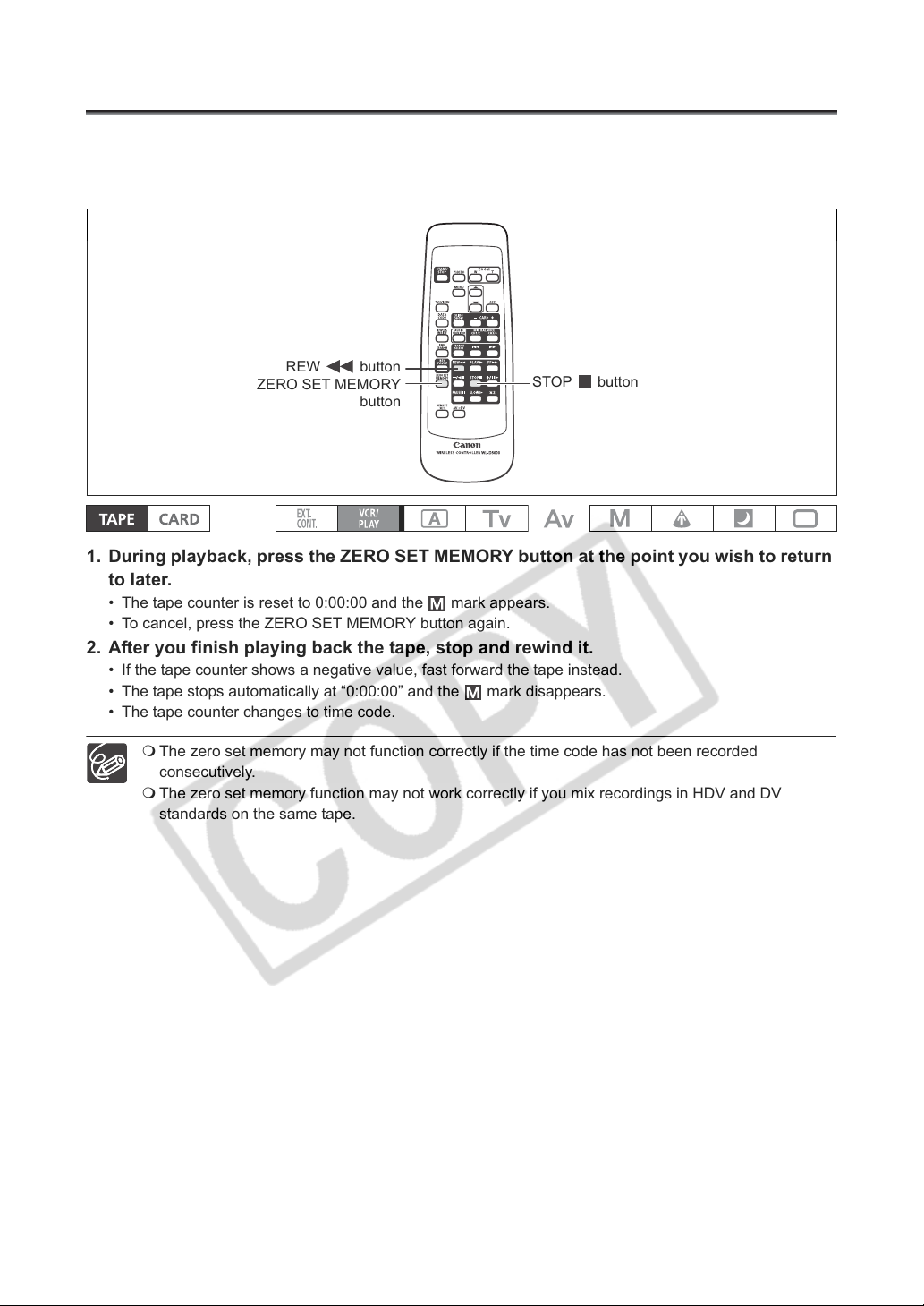
Returning to a Pre-marked Position
If you wish to return to a particular scene later, mark the point with the zero set memory, and the tape will
stop at that point when you rewind/fast forward the tape.
This function is operated with the wireless controller.
REW button
ZERO SET MEMORY
button
STOP button
1. During playback, press the ZERO SET MEMORY button at the point you wish to return
to later.
• The tape counter is reset to 0:00:00 and the mark appears.
• To cancel, press the ZERO SET MEMORY button again.
2. After you finish playing back the tape, stop and rewind it.
• If the tape counter shows a negative value, fast forward the tape instead.
• The tape stops automatically at “0:00:00” and the mark disappears.
• The tape counter changes to time code.
The zero set memory may not function correctly if the time code has not been recorded
consecutively.
The zero set memory function may not work correctly if you mix recordings in HDV and DV
standards on the same tape.
98
Page 99
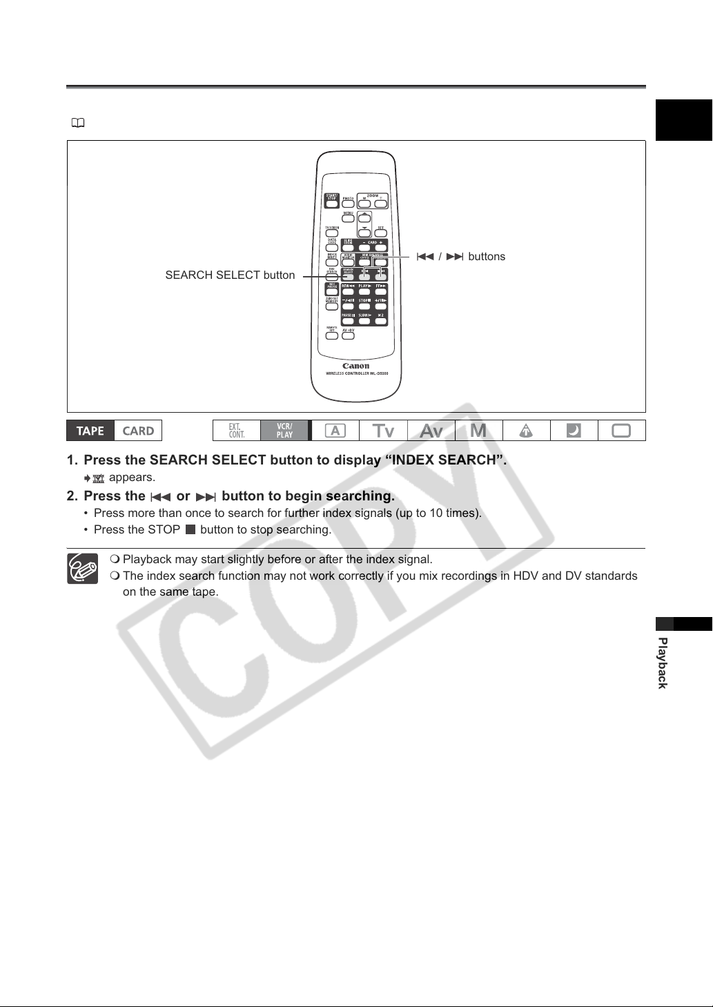
Index Search
With the index search you can locate any point you have marked beforehand with an index signal
( 67). This function is operated with the wireless controller.
/ buttons
SEARCH SELECT button
1. Press the SEARCH SELECT button to display “INDEX SEARCH”.
appears.
2. Press the or button to begin searching.
• Press more than once to search for further index signals (up to 10 times).
• Press the STOP button to stop searching.
E
Playback may start slightly before or after the index signal.
The index search function may not work correctly if you mix recordings in HDV and DV standards
on the same tape.
99
Playback
Page 100
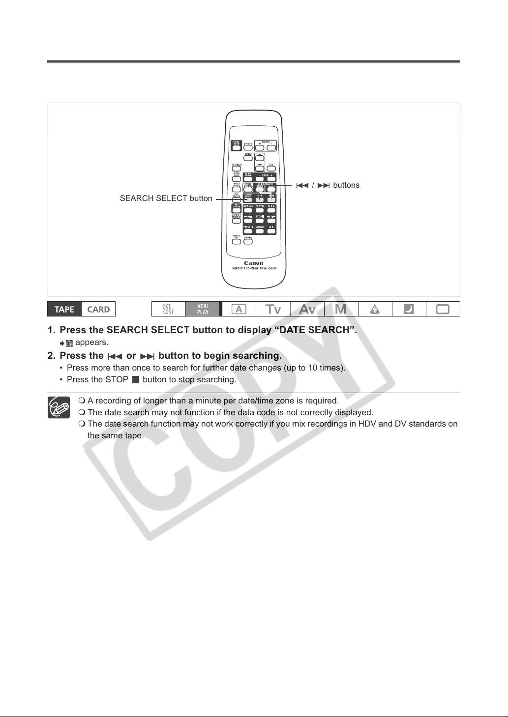
Date Search
You can locate the change of the date/time zone with the date search function.
This function is operated with the wireless controller.
/ buttons
SEARCH SELECT button
1. Press the SEARCH SELECT button to display “DATE SEARCH”.
appears.
2. Press the or button to begin searching.
• Press more than once to search for further date changes (up to 10 times).
• Press the STOP button to stop searching.
100
A recording of longer than a minute per date/time zone is required.
The date search may not function if the data code is not correctly displayed.
The date search function may not work correctly if you mix recordings in HDV and DV standards on
the same tape.
 Loading...