


Wireless File Transmitter
COPY
WFT-E4
WFT-E4A
This product is offered in two versions, WFT-E4 and WFT-E4A. Each version operates on a
different number of wireless LAN channels. The WFT-E4 can transmit on 13 channels, and the
WFT-E4A, on 11 channels. This difference in the number of channels available is due to
varying radio regulations in areas of use.
In other respects, the WFT-E4 and WFT-E4A are identical. They are operated in the same
way. This instruction manual describes operation using the WFT-E4 as an example.
E
INSTRUCTION MANUAL
Thank you for purchasing a Canon product.
COPY
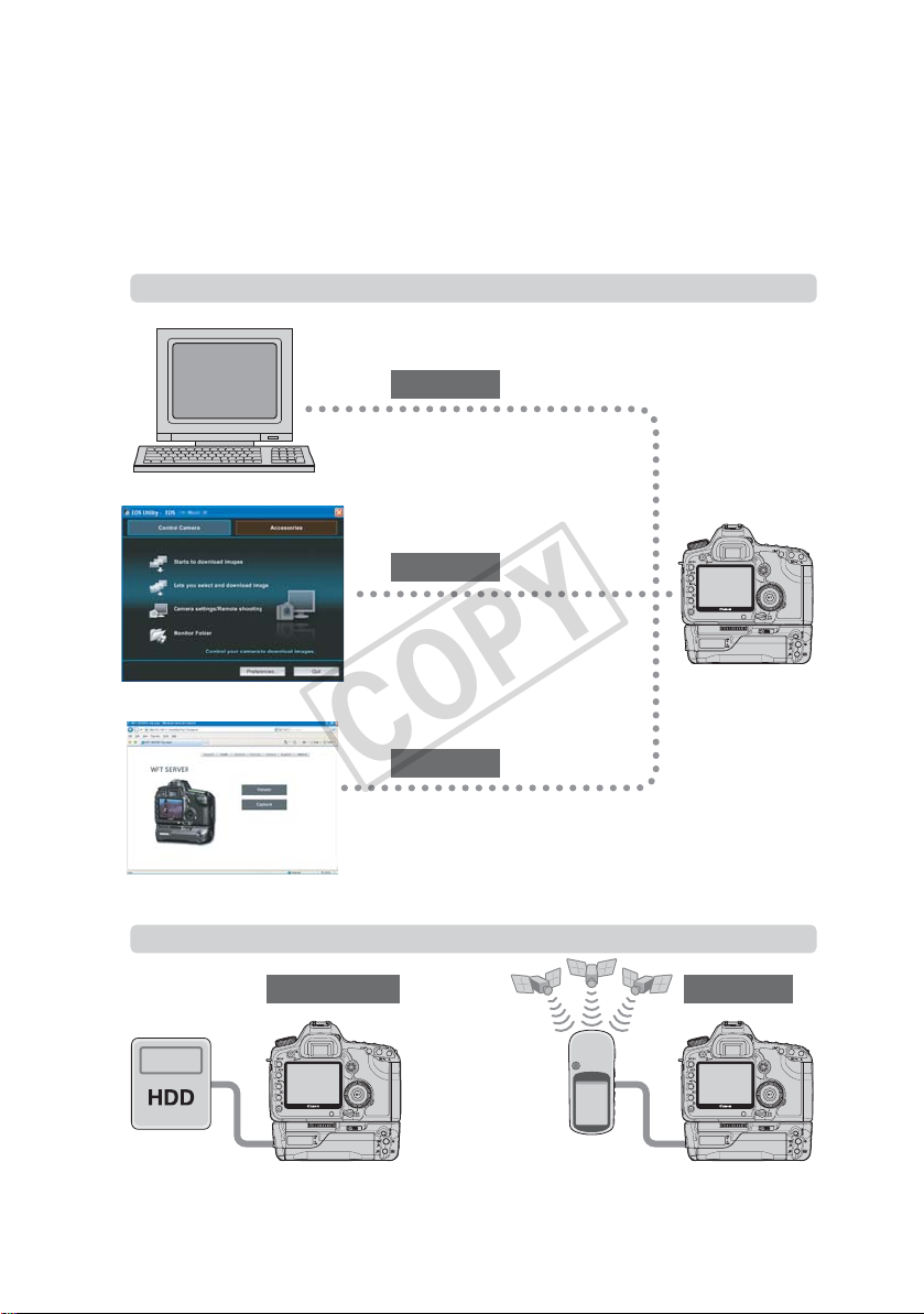
The Wireless File Transmitter WFT-E4 is an accessory for EOS 5D Mark II camera. It gives the
camera wireless and wired LAN functionality and adds a USB port, enabling the following
operations. The WFT-E4 is compatible with IEEE 802.11b and IEEE 802.11g wireless LANs as
well as 100 Base-TX Ethernet wired LANs.
It also includes a vertical-grip shutter button for convenience in vertical shooting.
Wireless and Wired LAN Functions
FTP
Transfer images to an FTP server
PTP
Use EOS Utility to capture, view, and
download images remotely
HTTP
Use a web browser to capture, view,
and download images remotely
Functions When Connected via USB
External Media
Record or backup images onto external media Add the latitude, longitude, altitude, date and
time, and other shooting information to images
2
GPS

Conventions Used in this Manual
COPY
These instructions should be followed only after your wireless or wired LAN and FTP server
settings are complete. For details on configuring these settings, refer to the documentation
provided with the respective equipment.
Terms in brackets [ ] indicate button or icon names or other software elements. Brackets
also denote camera menu items.
Page numbers in parentheses indicate where you can find additional information.
Instructions on camera operations should be followed only after you have read the Camera
Instruction Manual and are familiar with operating the camera.
Sections of this manual labeled with the following symbols contain information of the
corresponding nature.
: Warnings to avoid potential problems are labeled with a caution symbol.
: Supplemental information is labeled with a note symbol.
Windows is a trademark or registered trademark of Microsoft Corporation in the United
States and other countries.
Macintosh is a registered trademark of Apple Corporation in the United States and other
countries.
Wi-Fi is a registered trademark of the Wi-Fi Alliance.
Wi-Fi Certified, WPA, WPA2, and the Wi-Fi Certified logo are trademarks of the Wi-Fi
Alliance.
WPS as used on camera settings screens and in this manual signifies Wi-Fi Protected
Setup.
UPnP is a trademark of the UPnP Implementers Corporation.
All other corporate and brand names in this manual are trademarks or registered
trademarks of their respective owners.
Introduction
Using the transmitter for remote image transfer, capture, or viewing requires adequate knowledge of
configuring your wireless or wired LAN and FTP server.
Canon cannot provide support for configuring wireless or wired LANs or FTP servers.
Note that Canon cannot be held liable for any loss or damage to the transmitter from erroneous network
or FTP server settings. In addition, Canon cannot be held liable for any other loss or damage caused by
use of the transmitter.
3

Contents
COPY
Introduction
Conventions Used in this Manual ...................................................................................................... 3
Areas of Use and Restrictions ........................................................................................................... 6
Safety Warnings................................................................................................................................. 7
Nomenclature..................................................................................................................................... 8
Attaching to the Camera .................................................................................................................. 10
Vertical Shooting Controls ............................................................................................................... 11
Installing and Removing the Battery ................................................................................................ 12
Using a Household Power Outlet ..................................................................................................... 14
Subsequent Organization of This Manual........................................................................................ 15
1 Basic Network Settings 17
Displaying the Connection Wizard................................................................................................... 18
Selecting the Communication Method and LAN Type ..................................................................... 19
Using the Wizard to Establish a Connection.................................................................................... 21
WPS Connections (PBC Mode)....................................................................................................... 23
WPS Connections (PIN Mode) ........................................................................................................ 24
Configuring Network Settings .......................................................................................................... 25
2 FTP Settings and Image Transfer 29
Configuring FTP Transfer Settings .................................................................................................. 30
Automatic Image Transfer After Each Shot ..................................................................................... 32
Transferring Images Individually ...................................................................................................... 34
Batch Transfer ................................................................................................................................. 36
Checking Image Transfer History .................................................................................................... 40
Viewing Transferred Images............................................................................................................ 41
3 PTP Settings and Remote Capture 43
Configuring PTP Transfer Settings .................................................................................................. 44
Using EOS Utility ............................................................................................................................. 47
4 HTTP Settings and Remote Capture 49
Configuring HTTP Transfer Settings................................................................................................ 50
Displaying WFT Server .................................................................................................................... 52
Shooting Remotely........................................................................................................................... 53
Viewing Images................................................................................................................................ 55
5 Managing Settings Information 57
Checking Settings ............................................................................................................................ 58
Changing Settings............................................................................................................................ 59
Saving and Loading Settings........................................................................................................... 61
6 Using External Media 63
Connecting External Media.............................................................................................................. 64
Choosing Recording Media When Shooting.................................................................................... 67
Using Together With a CF Card....................................................................................................... 69
Backing Up on External Media......................................................................................................... 70
4

Contents
COPY
7 Using GPS Devices 75
Connecting GPS Devices ................................................................................................................ 76
8 Troubleshooting 79
Responding to Error Messages ....................................................................................................... 80
Wireless LAN Notes ......................................................................................................................... 93
Checking Network Settings .............................................................................................................. 94
1
9 Reference 95
WFT Utility (Software) ...................................................................................................................... 96
Creating and Registering Captions.................................................................................................. 98
Specifications................................................................................................................................... 99
Index .............................................................................................................................................. 105
2
3
4
5
6
7
8
9
5

Areas of Use and Restrictions
COPY
The WFT-E4 can be used only in the following areas.
Japan, France, Italy, Germany, United Kingdom, Belgium, the Netherlands, Luxembourg,
Ireland, Denmark, Greece, Spain, Portugal, Austria, Finland, Sweden, Poland, Hungary,
Romania, Bulgaria, Czech Republic, Slovakia, Slovenia, Estonia, Latvia, Lithuania, Cyprus,
Malta, Iceland, Norway, Switzerland, Lichtenstein, Australia, New Zealand, Singapore,
Russia and China
The WFT-E4A can be used in the United States and Canada, in addition to the previous
areas.
For information on other areas where the transmitter can be used, contact the Canon
Service Center.
The WFT-E4, which operates on wireless LAN frequencies for 13 channels, cannot be used
in the United States or Canada. Instead, use the WFT-E4A, which operates on wireless LAN
frequencies for 11 channels.
In France, using the transmitter outdoors is prohibited.
In Italy, use outside of one’s own premises requires general authorization.
In Latvia, use outside of one’s own premises requires an individual radio license.
The following actions may be punishable under law. Disassembling or modifying the
transmitter, or removing the certification label on it.
Do not use the transmitter near other devices that emit radio waves, such as medical
equipment or electronic devices. The transmitter may interfere with operation of these
devices.
Use the transmitter only with a compatible EOS DIGITAL camera. Using it with incompatible
cameras may cause malfunction, accidents, and other problems not covered under
warranty.
Use the transmitter as a wireless or wired LAN device as described in this instruction
manual. If you use the transmitter for any other purpose, Canon cannot be held liable for
any loss or damage that may occur.
6

Safety Warnings
COPY
The following precautions are intended to prevent harm to you and others as well as damage to
equipment. Become familiar with the precautions before using the transmitter to ensure correct
and safe operation.
Be sure that you fully understand the safety precautions contained in the instruction manuals
for the battery, charger, and AC Adapter Kit before using them.
Warning Preventing Serious Injury or Death
To prevent fire, excessive heat, chemical leakage, or explosion, follow these safety guidelines.
• Do not insert metallic objects between electrical contacts of the transmitter, accessories, or connecting cables.
Do not use the transmitter where there is flammable gas. There is a risk of explosion or fire.
If the transmitter is dropped and internal parts are exposed, do not touch the exposed parts. There is a risk of
electrical shock.
Do not disassemble or modify the transmitter. High-voltage internal parts may cause electrical shock.
Do not store the transmitter in dusty or humid places. There is a risk of fire or electrical shock.
Before using the transmitter on board airplanes or in hospitals, make sure use is permitted. Electromagnetic
waves emitted by the transmitter may interfere with instrumentation or medical equipment.
Caution Preventing Injury or Equipment Damage
Do not leave the transmitter inside a vehicle in hot weather or near a heat source. The transmitter may become
hot and cause burns if touched.
Do not cover or wrap the transmitter with a cloth. This may trap heat inside, posing a risk of case deformation or
fire.
Do not use paint thinner, benzene, or other organic solvents to clean the transmitter. This poses a risk of fire and
may be hazardous to your health.
If the product malfunctions, becomes damaged, or requires repair, contact your dealer
or the nearest Canon Service Center.
Handling Precautions
The transmitter is a precision instrument. Do not drop it or subject it to shock.
The transmitter is not waterproof. Do not use it underwater.
Wipe off any moisture with a clean, dry cloth. If the transmitter has been exposed to salty air,
wipe it with a clean damp cloth after wringing it out to remove excess water.
Never leave the transmitter near any equipment that generates a strong magnetic field,
such as magnets or electric motors.
Do not leave the transmitter in excessive heat, such as in a vehicle in direct sunlight. High
temperature may damage the transmitter.
Do not wipe the transmitter using cleaners containing organic solvents. If the transmitter
becomes difficult to clean, take it to the nearest Canon Service Center.
To avoid corrosion, do not store the transmitter where there are strong chemicals, such as in
darkrooms or chemical labs.
Introduction
7
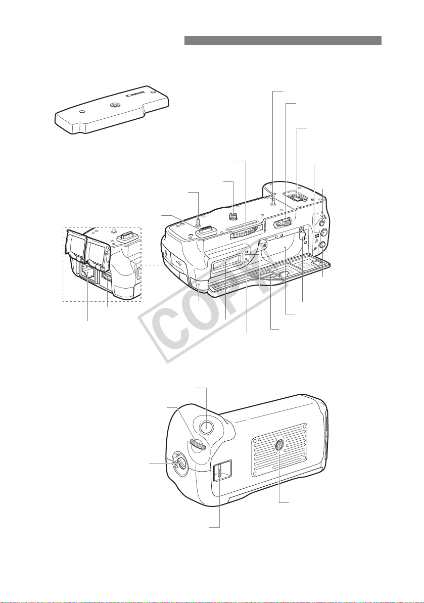
Nomenclature
COPY
Protective cover
* Turn the attachment knob to remove.
Attachment knob
Positioning pin
Battery compartment
cover release lever
Terminal cap holder
AE lock/FE lock/
Index/Reduce button
USB port
Ethernet RJ-45 port
Vertical-grip
<
ON/OFF
Positioning pin
Terminal
Main dial
> switch
Tripod screw
DC coupler
cord notch
LCD panel
<
LAN
> Network lamp
Shutter button
<
USB
> USB lamp
AF start button
AF point selection/
Magnify button
Battery lock lever
Battery compartment
Battery compartment cover
Tripod socket
Hand strap mount
8
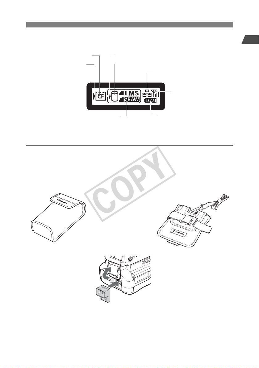
LCD panel
COPY
Nomenclature
Introduction
CF card loading indicator
CF card selection mark
Recording quality at [Rec. separately] setting
Accessories
Transmitter Case
External media selection mark
External media connection indicator
Wired LAN connection
Wireless LAN connection
Battery level indicator
External Media Case*
1
Waterproof/Dustproof USB Cap*
*1: This can hold portable hard disks and other devices up to 120 x 75 x 15 mm / 4.72 x 2.95 x 0.59 in. in size.
*2: Attach this cap before connecting the USB cable in rainy weather or under other adverse conditions.
2
9
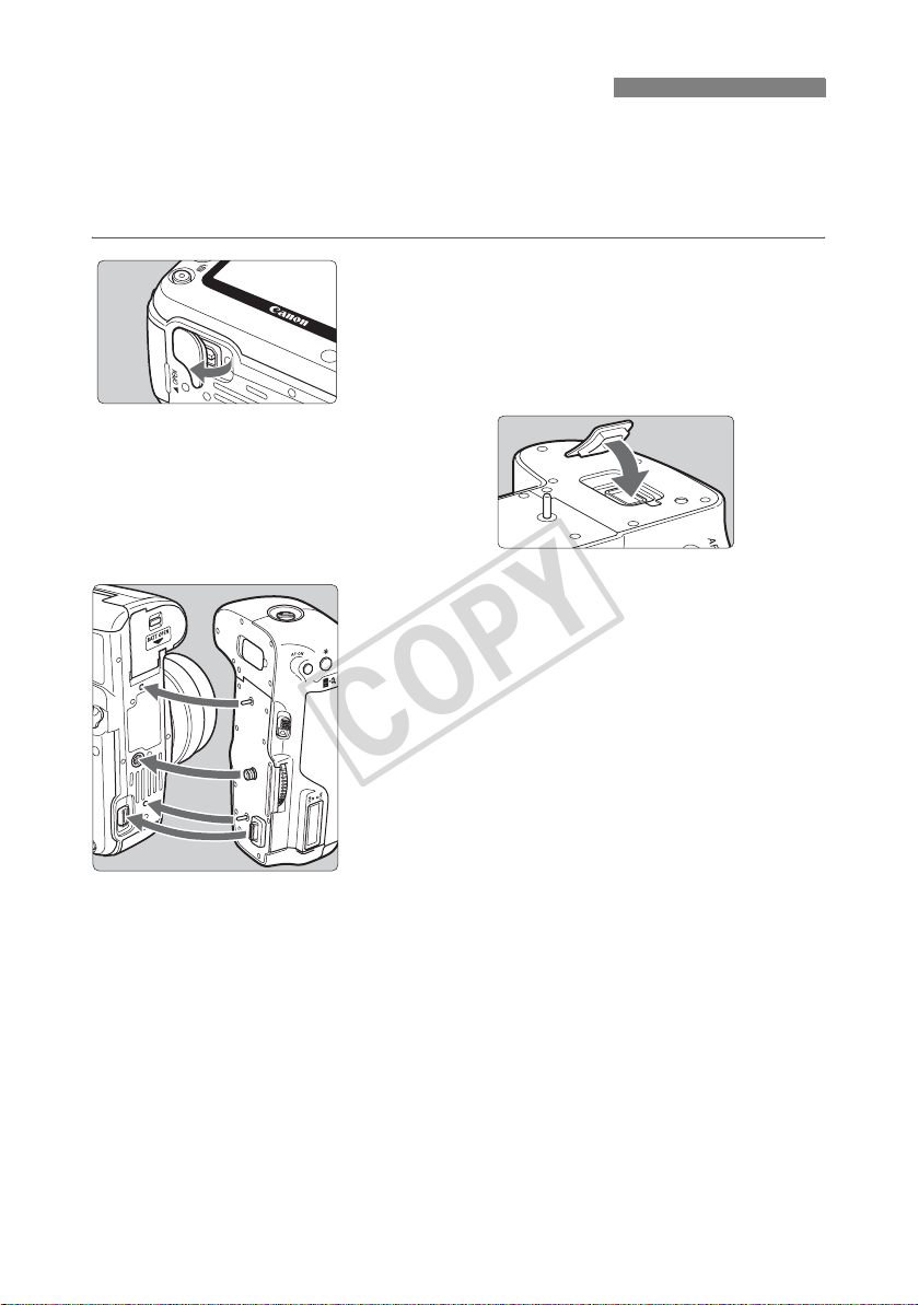
Attaching to the Camera
COPY
Load a charged battery into the camera. Before attaching the transmitter to the camera, set the
OFF
camera’s power switch to <
and off in conjunction with the camera’s power switch.
Before removing the transmitter, set the camera’s power switch to <
>. The transmitter does not have a power switch. It is turned on
OFF
>.
Remove the terminal cap from the
camera.
1
Peel off the terminal cap on the camera bottom to
remove.
Attach the removed terminal cap to the
transmitter’s terminal cap holder.
Attach the transmitter.
2
As shown in the figure, align the transmitter and
the camera, and turn the attachment knob to
attach to the camera.
10
Vertical Shooting Controls
COPY
Setting the vertical-grip <ON/
enables the vertical-grip shutter button and other
controls. These controls for shooting can still be used
even when batteries are not loaded in the transmitter.
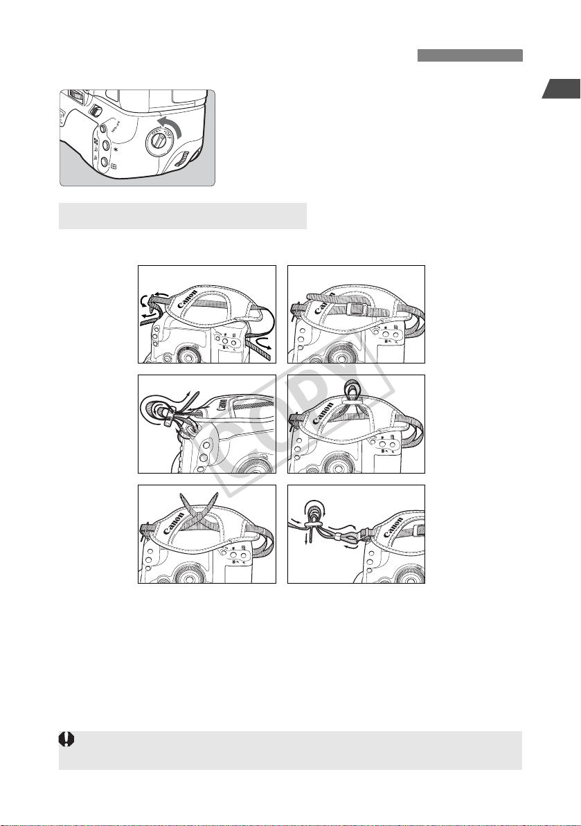
Attaching the Hand Strap E1
The Hand Strap E1 (sold separately) is attached as shown in the figure.
1 4
2 5
3 6
OFF
> switch to <ON>
Introduction
After the hand strap is attached, check that all the slack at the buckle is removed and that there is no
looseness at the buckle even when pulled tight.
11
Installing and Removing the Battery
COPY
Use one Battery Pack LP-E6 to power the transmitter. When replacing the transmitter’s battery,
OFF
be sure to first set the camera’s power switch to <
compartment cover. In particular, if the transmitter’s battery compartment cover is opened without
setting the camera’s power switch to <
the connection operation for the external media or GPS device will have to be performed again.
The
transmitter’s
separately.
Installing the battery
battery is not included. Customers who do not have one should purchase it
OFF
> when an external media or a GPS device is connected,
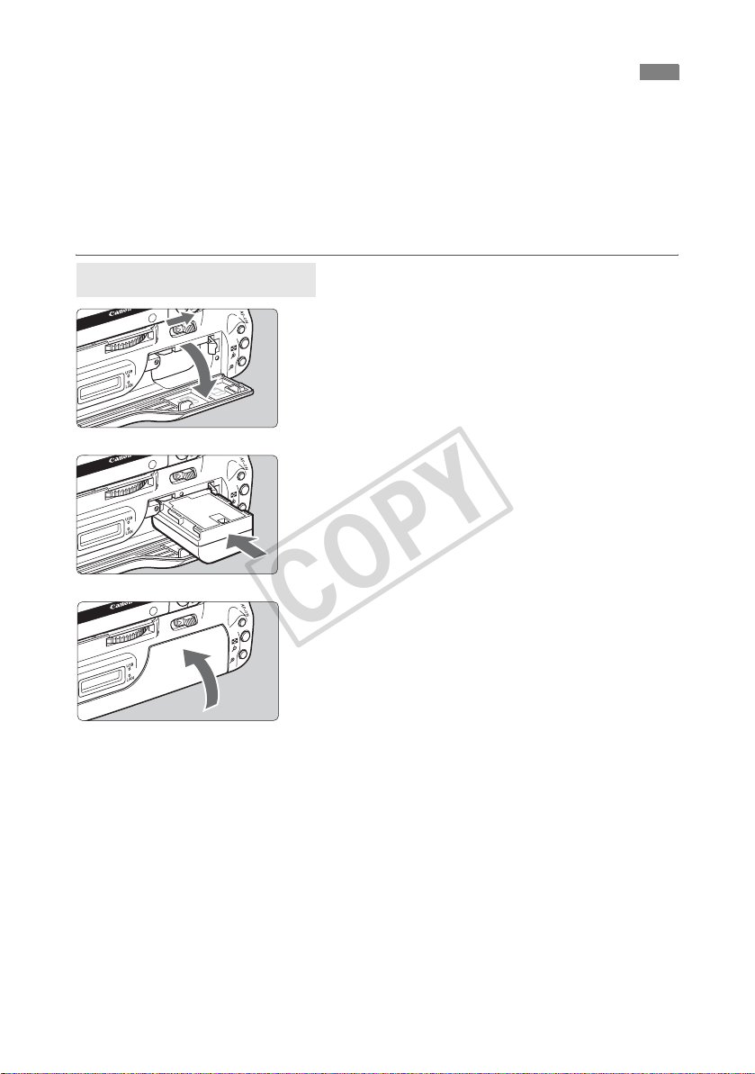
Open the cover.
1
Slide the lever to open the cover.
Insert the battery.
2
Insert from the side with battery contacts.
Insert the battery all the way until it locks into
> before opening the transmitter’s battery
place.
12
Close the cover.
3
Press the cover up until it clicks into place.
Installing and Removing the Battery
COPY
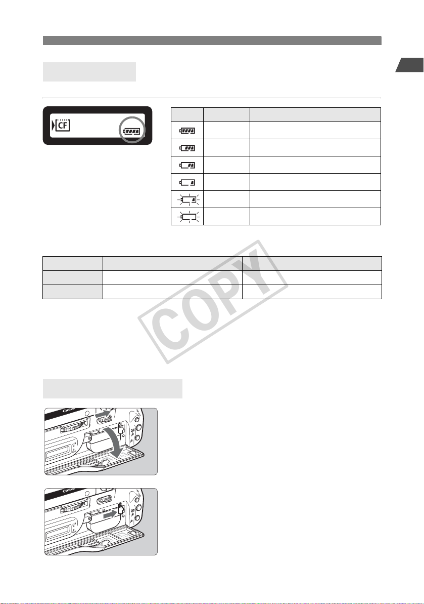
Battery check
The remaining battery power is displayed when the camera is turned on.
Icon Level (%) Status
100 - 70 Sufficient battery level
69 - 50 Battery level exceeds 50%
49 - 20 Battery level below 50%
19 - 10 Battery level is low
9 - 1 Battery will be exhausted soon
0 Recharge the battery
Number of images that can be transferred Approx. number of images
LAN At Normal Temperature (23°C / 73°F) At Low Temperature (0°C / 32°F)
Wireless LAN 2100 2100
Wired LAN 2400 2400
Using a fully charged LP-E6. The number of images that can be transferred is nearly the
same at normal temperature (23°C / 73°F) and low temperature (0°C / 32°F).
When automatic transfer is performed during shooting of an image of approx. 6.1 MB under
conditions based on the CIPA (Camera & Imaging Products Association) test standards.
Fewer images can be transferred when transferring images over a wireless LAN.
Fewer images can be transferred when using bus-power external media or GPS devices.
Introduction
Removing the battery
1
2
Open the cover.
Slide the lever to open the cover.
Remove the battery.
Press the battery lock lever in the direction of the
arrow to unlock, and then unload the battery.
To prevent a short-circuit, be sure to always attach
the protective cover to the battery.
13

Using a Household Power Outlet
COPY
When the AC Adapter Kit ACK-E6 (sold separately) is used, a household power outlet can be
used to power the camera without worrying about the battery level.
Connect the DC coupler plug.
1
Connect the DC coupler plug to the socket of the
AC adapter.
Connect the power cord.
2
Connect the power cord as shown.
Insert the plug into the outlet.
After usage, unplug from the outlet.
Insert the DC coupler.
3
Open the cover, and insert the DC coupler firmly
until the lock position.
Close the cover.
4
Pass the cord through the groove while opening
the cap of the DC coupler cord notch, and then
close the cover.
Do not connect or disconnect the power cord while the camera’s power switch is set to <ON> or < >.
14

Subsequent Organization of This Manual
COPY
In addition to wireless and wired LAN functions, the WFT-E4 can communicate with external
media and GPS devices.
For instructions on operations after you have attached the transmitter to the camera, click one
of the following chapter titles to view the corresponding page.
Using a Wireless or Wired LAN
(Basic Network Settings)
Chapters 1 to 5
Using External Media
Chapter 6
Using GPS Devices
Chapter 7
Introduction
15

16
COPY

Basic Network Settings
COPY
Complete the basic network settings by following transmitter connection
instructions on the camera menu screen.
Getting Ready
The connection instructions help you follow the steps to connect the transmitter to an
existing wireless or wired LAN.
To connect to a wireless LAN, prepare the wireless LAN device (wireless LAN access
point or wireless LAN adapter) and computer in advance so that they are ready for
you to connect the transmitter to the wireless network. When configuring the basic
network settings, bring the transmitter within 3 m / 9.8 ft. of the wireless LAN device.
To connect to a wired LAN, use a LAN cable to connect the transmitter and computer.
Prepare the transmitter for connection to the wired network.
1
Wireless Transmission of Movie
Individual movie files are large, and wireless file transmission takes some time. When
preparing an environment for stable transmission to the wireless LAN device, refer to
the information on page 93.
17
Displaying the Connection Wizard
COPY
This section describes the process of following the connection instructions. If an error is
displayed, refer to “Troubleshooting” in Chapter 8 (p.79) and check the settings.
Pressing the shutter button or other camera controls during configuration by the connection
instructions will close the connection instructions. Do not press the shutter button or other
controls until configuration is finished.
On the [5] tab, set [Auto power off] to [Off]. If auto power off is activated, the connection
instructions will be closed during the configuration process.
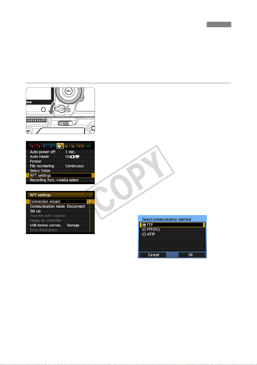
Turn the camera on.
1
Display the transmitter menu.
2
On the camera, press the <7> button.
On the [5] tab, select [WFT settings] and press
<0>. [WFT settings] is added to the tab after
you attach the transmitter.
Select [Connection wizard].
3
X The [Select communication method] screen is
displayed.
18
X The <
LAN
> lamp starts blinking.

Selecting the Communication Method and LAN Type
COPY
Selecting the Communication Method
Turn the <5> dial to select the communication
method, and then press <0>.
Select [OK] and press <0> to go to the next
screen.
• FTP
Choose this option to transfer captured images to an FTP server.
Images can be automatically transferred as you shoot them, or you can select images for
transfer later.
Computer Operating Systems
Operation via [FTP] requires that Windows Vista (Business, Enterprise, or Ultimate Edition
for 32- or 64-bit systems), Windows XP Professional, Windows 2000, or Mac OS X 10.4/10.5
be installed on your computer. In addition, the computer must be prepared as an FTP server
in advance.
For instructions on preparing your computer as an FTP server, refer to the computer
documentation.
Windows Vista Home Premium and Home Basic Edition as well as Windows XP Home
Edition cannot be used because FTP server functionality is not supported.
1
Basic Network Settings
• PTP
Choose this option when using EOS Utility for remote capture over a wireless or wired LAN.
In addition to remote capture, all camera operations in EOS Utility are supported because a
wireless or wired network is used with this option instead of the USB cable.
Computer Operating Systems
Operation via [PTP] requires that any edition of Windows Vista for 32- or 64-bit systems
(except Starter Edition), Windows XP (Home Edition or Professional, with Service Pack 2),
or Mac OS X 10.4/10.5 be installed on your computer.
• HTTP
Choose this option for remote capture over a wireless or wired LAN.
In addition, images on a CF card in the camera can be viewed and downloaded to a computer.
The camera can be accessed like browsing a webpage, by users at up to three computers.
Computer Operating Systems
Any computer with a web browser can be used, regardless of the operating system.
19
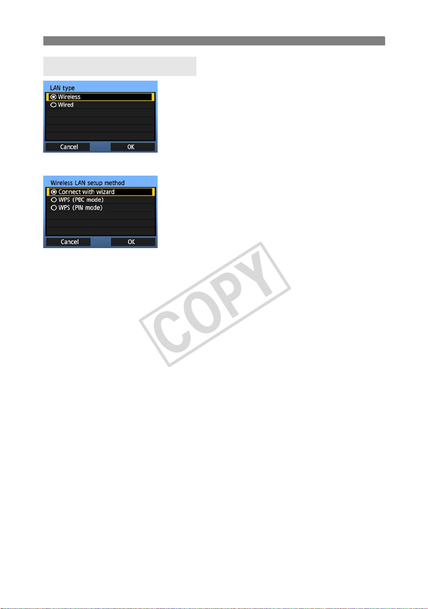
Selecting the Communication Method and LAN Type
COPY
Selecting the LAN Type
Turn the <5> dial to select the type of LAN, and
then press <0>.
Select [OK] and press <0> to go to the next
screen.
Wireless LAN
The [Wireless LAN setup method] screen is
displayed.
[Connect with wizard]: See p.21
[WPS (PBC mode)]: See p.23
[WPS (PIN mode)]: See p.24
Select [WPS (PBC mode)] or [WPS (PIN mode)]
when using a wireless LAN device compatible with
Wi-Fi Protected Setup (WPS).
Wired LAN
The [Network] settings screen is displayed. If you have selected a wired network, refer to page
25, “Configuring Network Settings.”
Use a Category 5 or higher STP LAN cable. (STP: Shielded Twisted Pair)
20
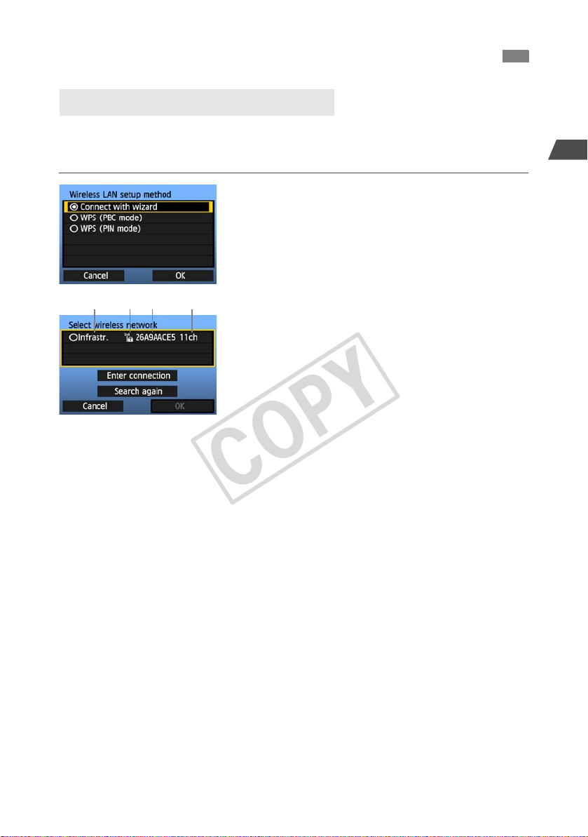
Using the Wizard to Establish a Connection
123 4
COPY
Selecting the Wireless Network
When you select [Connect with wizard], active wireless LAN devices in your area are listed,
accompanied by information about them. Select the SSID (or ESS-ID) of your desired wireless
LAN device.
Select [Connect with wizard].
1
Turn the <5> dial to select [Connect with
wizard], and then press <0>.
Select the wireless LAN device.
2
To select the wireless LAN device, press <0>.
Turn the <5> dial to select the wireless LAN
device, and then press <0>.
Select [OK] and press <0> to go to the next
screen.
1 Indicates whether the device is in infrastructure or ad hoc mode
2 An icon is displayed if the wireless LAN device is encrypting communication
3 Indicates the first 9 characters of the SSID
4 Indicates the channel used
Encryption by Wireless LAN Devices
If the wireless LAN device is encrypting communication, select the corresponding method in
[Authentication] and [Encryption].
[Authentication]: Open system, Shared key, WPA-PSK, or WPA2-PSK
[Encryption]: WEP, TKIP, or AES
1
Basic Network Settings
[Enter connection] and [Search again]
To configure settings for the wireless LAN device manually, select [Enter connection] and
press <0>. Complete the settings for the items displayed, one after another.
To search for wireless LAN devices again, select [Search again] and press <0>.
21
Using the Wizard to Establish a Connection
COPY
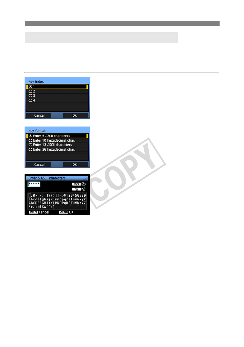
Entering the Wireless LAN Encryption Key
Next, enter the encryption key of the wireless LAN device. For details on the encryption key,
refer to the device’s instruction manual.
Note that the screens displayed in steps 1 to 3 below vary depending on the authentication and
encryption of the wireless LAN device.
The [Key index] screen is displayed only if WEP
1
2
3
encryption is used by the wireless LAN device.
Turn the <5> dial to select the key index number
specified as the access point, and then press
<0>.
Select [OK] and press <0> to go to the next
screen.
Turn the <5> dial to select the key format, and
then press <0>.
Select [OK] and press <0> to go to the next
screen.
Enter the encryption key.
To switch between input areas, press the <A>
button.
To move the cursor, turn the <5> dial.
In the bottom input area, turn the <5> dial and
press <0> to enter the encryption key.
If you make a mistake, press the <L> button to
erase it.
When you press the <7> button to complete
the connection with the wireless LAN device, the
[Network] screen (p.25) is displayed.
To return to the previous screen, press the
<6> button. The entry is erased.
22
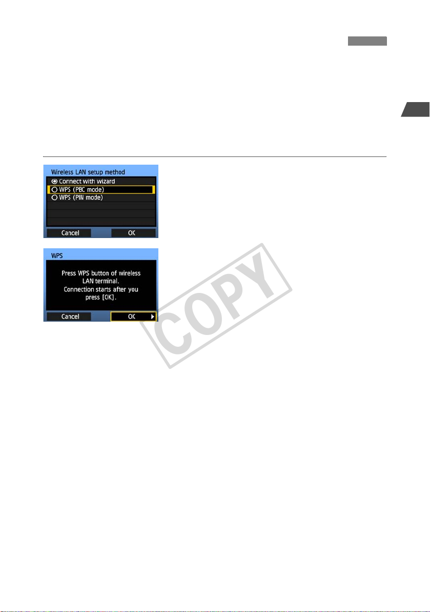
WPS Connections (PBC Mode)
COPY
This is a connection mode when using a wireless LAN device compatible with Wi-Fi Protected
Setup (WPS). Pushbutton Connection mode (PBC mode) makes it easy to establish a
connection between the camera and the wireless LAN device by pressing the WPS button on
the wireless LAN device.
Note that if multiple wireless LAN devices are active in your area, it may be harder to establish
a connection. In this case, try using [WPS (PIN mode)] to establish a connection.
Confirm the position of the WPS button on the wireless LAN device in advance.
It may take about one minute to establish connection.
Select [WPS (PBC mode)].
1
Turn the <5> dial to select [WPS (PBC mode)],
and then press <0>.
Select [OK] and press <0> to go to the next
screen.
Establish a connection with the
wireless LAN device.
2
Press the WPS button on the wireless LAN device.
For details about where the button is located and
how long to press it, refer to the instruction manual
of the wireless LAN device.
Select [OK] and press <0> to establish a
connection with the wireless LAN device.
When the connection with the wireless LAN device
is established, the [Network] screen (p.25) is
displayed.
1
Basic Network Settings
23
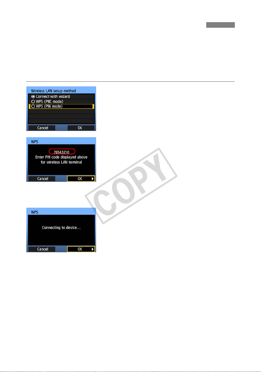
WPS Connections (PIN Mode)
COPY
This is a connection mode when using a wireless LAN device compatible with Wi-Fi Protected
Setup (WPS). In PIN code connection mode (PIN mode), an 8-digit identification number
specified on the camera is set on the wireless LAN device to establish a connection.
Even if there are multiple wireless LAN devices active in your area, this is a relatively reliable
method of establishing a connection using a shared identification number.
It may take about one minute to establish connection.
Select [WPS (PIN mode)].
1
Turn the <5> dial to select [WPS (PIN mode)],
and then press <0>.
Select [OK] and press <0> to go to the next
screen.
Specify the PIN code on the wireless
LAN device.
2
On the wireless LAN device, specify the 8-digit
PIN code shown on camera LCD monitor.
For instructions on setting PIN codes on the
wireless LAN device, refer to the instruction
manual of the wireless LAN device.
Select [OK] and press <0> to display the
confirmation screen.
24
Establish a connection with the
wireless LAN device.
3
Select [OK] and press <0> to establish a
connection with the wireless LAN device.
When the connection with the wireless LAN device
is established, the [Network] screen (p.25) is
displayed.
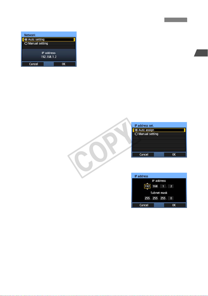
Configuring Network Settings
COPY
Turn the <5> dial to select how to configure the
network settings, and then press <0>.
Select [OK] and press <0> to go to the next
screen.
[Auto setting]
Settings otherwise configured with [Manual setting] can be configured automatically.
However, the IP address and similar settings must be automatically assigned and
configured in environments using DHCP servers or wireless LAN devices or routers
supporting DHCP server functions.
If an error is displayed, select [Manual setting] regardless of whether the IP address and
similar settings are automatically assigned and configured.
[Manual setting]
The [IP address set.] screen is displayed after you select
[Manual setting]. If [Auto setting] results in an error, enter
the IP address manually. As the IP address, enter the IP
address assigned to the camera.
Enter the [IP address], [Subnet mask], [Gateway], and
[DNS address] on each screen as they are displayed.
If you are not sure what to enter, refer to page 94, “Checking
Network Settings,” or ask the network administrator or
another person knowledgeable about the network.
When entering numbers for the IP address, subnet mask,
and so on, press <0> to move the input position and turn
the <5> dial to enter the number.
1
Basic Network Settings
25
Configuring Network Settings
COPY
Completing Settings for the Communication Method
The following instructions are for settings screens that vary depending on the communication
method (FTP, PTP, or HTTP), as shown below. Read the page that introduces the selected
communication method.
FTP
Chapter 2 (p.29)
PTP
Chapter 3 (p.43)
Windows Vista Users
Before performing the operations from page 43, perform the operations below. If these operations are
not performed, the WFT Pairing Software described on page 44 may not start.
Open the [
order), and then double-click the [WFT FirewallSettings] icon.
After performing this operation, perform the operation on page 43.
HTTP
26
C Drive
] [Program Files] [Canon] [EOS Utility] [WFTPairing] folder (in this
Chapter 4 (p.49)

Configuring Network Settings
COPY
Virtual Keyboard Operation
The virtual keyboard is displayed during entry of the encryption key, server name, and other
information.
Switching to other input areas
To switch between input areas, press the <A>
button.
Moving the cursor
To move the cursor, turn the <5> dial.
You can also move the cursor using <9>.
Entering text
In the bottom input area, turn the <5> dial to move
the cursor and press <0> to enter text.
You can also move the cursor using <9>.
Deleting text
If you make a mistake, press the <L> button to erase
it.
Confirming entries
Press the <7> button to confirm what you have
entered and go to the next screen.
1
Basic Network Settings
Canceling entries
Press the <6> button to erase the entry and
return to the previous screen.
27

28
COPY

FTP Settings and
COPY
Image Transfer
You can configure the FTP settings for automatic transfer of each image as
you shoot or batch transfer after capture.
2
29
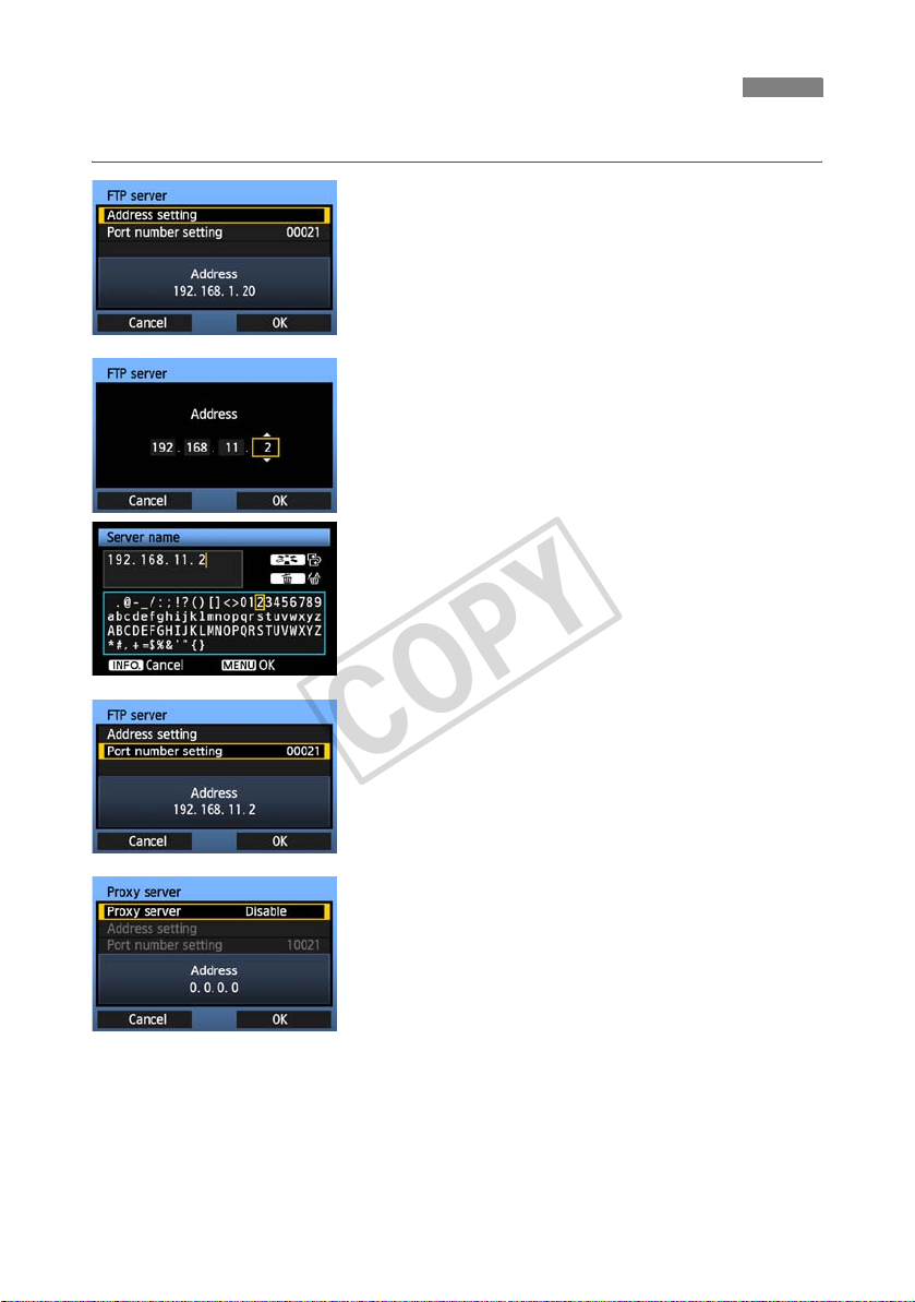
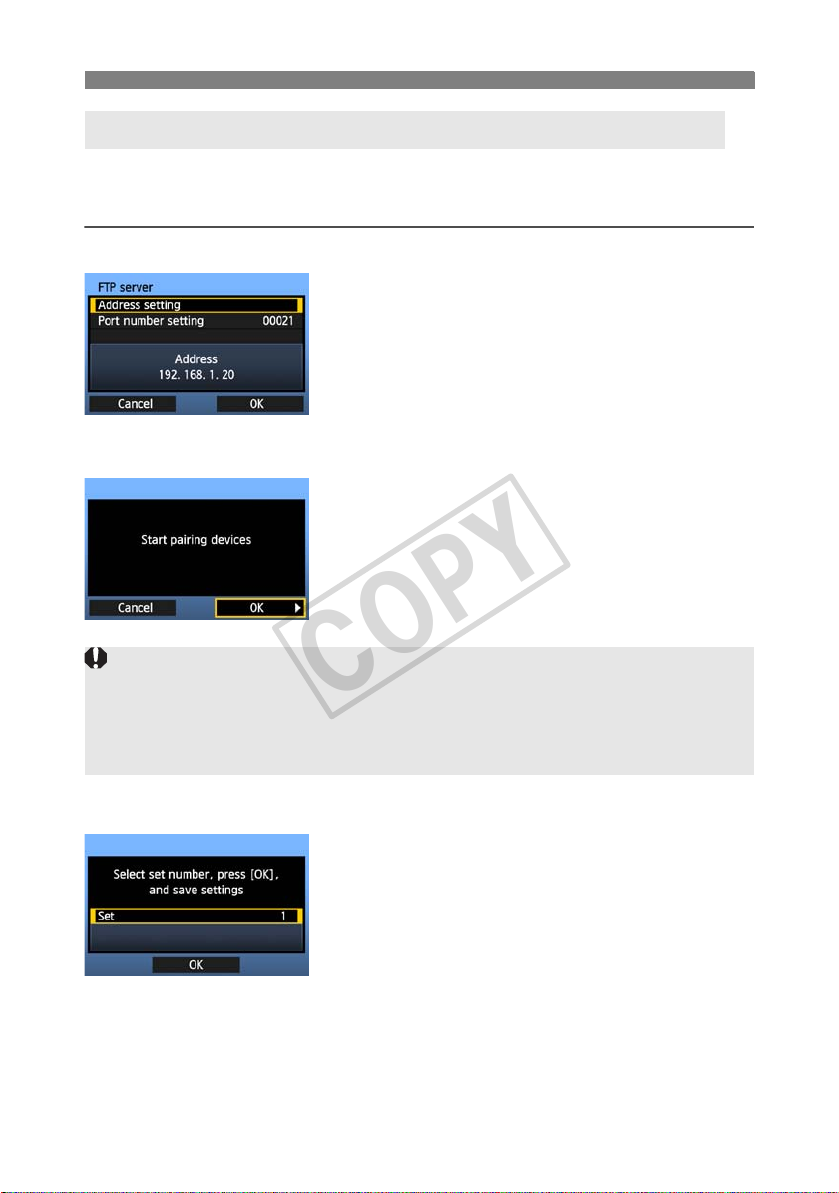
Configuring FTP Transfer Settings
COPY
These instructions are continued from Chapter 1.
Turn the <5> dial to select [Address setting],
1
2
3
and then press <0>.
If you have set the DNS server setting to
[Disable], the screen at left is displayed.
Press <0> to select the input position, and then
turn the <5> dial to enter the IP address of the
FTP server.
If you have set the DNS server IP address setting
to [Auto assign] or [Manual setting], the screen
at left is displayed.
For instructions on screen operations, refer to
“Virtual Keyboard Operation” (p.27).
Enter the FTP server’s server name or IP address.
In [Port number setting], enter 00021, in most
cases.
Turn the <5> dial to select [OK], and then press
<0> to go to the next screen.
30
Complete the [Proxy server] settings.
Turn the <5> dial to select [OK], and then press
4
<0> to go to the next screen.
 Loading...