

High-performance Monitoring Software
User’s Manual
2
Requests to Customers
(1) The content of this manual may not be reproduced in its entirety or in part without prior
permission.
(2) The content of this manual is subject to change without notice.
(3) All possible measures have been taken to ensure that the content of this manual is accurate. If
you happen to notice errors, omissions or other faults, please contact Canon.
(4) Irrespective of items above, Canon cannot bear responsibility for any effects that results from
operation.
Icons Used in This Manual
Indicates notes of caution or limitations that must be kept in mind concerning operation. Be sure to
read these notes.
Indicates supplemental explanations or references that are useful for operation.
Indicates functions and specifications that are only available to VB150 users.
Copyright Information
Please note that copyright laws prohibit the customer from using recorded videos and still pictures for any purpose
other than personal enjoyment without permission from the copyright holder.
Trademarks
● Canon and Canon logo are registered trademarks of Canon Inc.
● Microsoft and Windows are trademarks or registered trademarks of Microsoft Corporation in the United States and
other countries.
● Windows is legally recognized as Microsoft Windows Operating System.
● All other company or product names used in this manual are trademarks or registered trademarks of their respective
holders.
c
Note
e
Tip
Introduction
Thank you for purchasing WebView Livescope MV Ver. 2.1. Please read this manual
prior to use to ensure that you will be able to use this software effectively.
When you finish reading this manual, please store it in a safe place.
The latest product information is available at the following Web site.
http://www.canon.com/webview/
VB150

Introduction
3
Contents
Introduction
Introduction............................................................................ 2
Overview................................................................................. 5
System Configuration ........................................................... 6
Tasks To Perform Prior To Monitoring................................. 8
Operating Environment......................................................... 10
Chapter 1 Installing
Prior to Installation................................................................ 12
Check the System Configuration .................................. 12
Preparing the Computers .............................................. 14
Installing the Camera Servers....................................... 14
Installation Procedures......................................................... 15
Starting Up the Installer................................................. 15
Installing MV Manager .................................................. 16
Installing MV Station ..................................................... 17
Chapter 2 Registering Camera Servers
Registering Camera Servers ................................................ 20
Camera Server Registration Wizards.................................. 22
Registering a Camera Server........................................ 22
Step 1: Start up the Register Camera Server Wizard ............................ 22
Step 2: Enter a network address for the camera server ........................ 22
Step 3: Enter a name and comment for the camera server................... 23
Step 4: Complete the settings................................................................. 23
Searching/Registering Camera Servers ....................... 25
Step 1: Start up the Serch/Register Camera Server Wizard ................. 25
Step 2: Search for and register the camera server ................................ 25
Step 3: Complete the settings................................................................. 26
Chapter 3 Creating Monitoring Screens
Creating Monitoring Screens ............................................... 28
Create Monitoring Screen Wizard ....................................... 30
Step 1: Start up the Create Monitoring Screen Wizard.......................... 30
Step 2: Select a monitoring screen......................................................... 30
Step 3: Select cameras ........................................................................... 31
Step 4: Enter monitoring screen name and comments.......................... 31
Step 5: Complete the settings................................................................. 32
Editing Maps .......................................................................... 40
Starting up Map Editor .................................................. 40
Loading and Changing Background Bitmaps................ 41
Allocating Icons ............................................................. 42
Saving the Edited Screen.............................................. 44
Chapter 4 Exporting MV Data
Exporting ................................................................................ 46
Operation Restriction............................................................ 48

4
Chapter 5 Monitoring
Starting up MV Station.......................................................... 50
Operating the Monitoring Screen ........................................ 54
Opening the Monitoring Screen .................................... 54
Allocating a Camera...................................................... 55
Deleting an Image ......................................................... 55
Reloading MV Data Again ............................................. 56
Switching Camera Source Windows............................. 56
Displaying and Switching the Camera Control Panel ... 57
Operating a Camera...................................................... 58
Full Screen Display ....................................................... 61
Video Pause/Resume.................................................... 61
Taking a Snapshot......................................................... 61
To Reconnect ................................................................ 62
Viewing Network Information ........................................ 62
Chapter 6 Managing the Camera Servers
Setting and Managing Camera Servers .............................. 64
Upgrading the Firmware ....................................................... 65
Chapter 7 Advanced Operations
Automatic Operation Functions of MV Station .................. 68
Auto Preset Tour............................................................ 68
Auto Switch ................................................................... 70
Video Relay ................................................................... 73
Examples of Using Automatic Operation ...................... 75
External Devices Input/Output............................................. 78
Notification of External Device Input ............................. 78
External Device Output Control .................................... 79
Motion Detection ................................................................... 80
Notification of Motion Detection .................................... 80
Recording and Viewing Pictures.......................................... 84
Picture Recording Settings............................................ 84
Using VBImageBrowser ................................................ 85
Downloading All Recorded Pictures ....................................................... 88
Comparing Images .................................................................................. 92
Sorting Images in Order of Similarity...................................................... 93
External Device Input/Motion Detection
and Picture Recording.................................................. 98
Other Advanced Settings...................................................... 99
MV Manager and its Other Functions and Settings ...... 99
MV Station and its Other Functions and Settings ......... 107
Appendix
Troubleshooting ..................................................................... 112
Error Messages...................................................................... 113
MV Manager Error Messages ....................................... 113
MV Station Error Messages .......................................... 116
Introduction
5
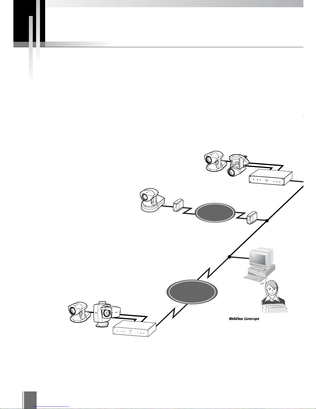
Overview
WebView Livescope MV Ver. 2.1 is software that allows you to use an Intranet or the Internet to
monitor images distributed from the Network Camera Server VB150/VB101 or the Network Camera
VB-C10/VB-C10R (hereafter referred to in this manual as "camera server").
This software consists of two packages: WebView Livescope MV Manager, that lets you create
monitoring screens or have centralized control of several camera servers; and WebView Livescope
MV Station, that lets you monitor images from cameras in multiple locations and easily download,
view, save, and manage pictures recorded in the camera server.
Since MV Manager uses the wizard format for registering camera servers or creating monitoring
screens, there is no need to learn complex operations. You can also have centralized control
(changing settings or confirming operating conditions) of camera servers installed in multiple
locations.
Monitoring screens can be created by selecting from a rich variety of screen styles to best suit the
size of the monitor, the number of camera servers and cameras, and monitoring objectives. It is
also possible to perform such tasks as editing maps, changing the allocation of camera servers on
the maps, or making settings for automatic operation based on schedules.
MV Station lets you access MV data created in MV Manager, freely remote control cameras, and
simultaneously view images from camera servers installed in multiple locations (up to 16 locations),
providing an efficient monitoring environment.
In MV Station, you can easily view and manage still pictures recorded by the camera server’s
picture recording function and automatically download them. Smoother and more accurate
monitoring is possible due to functions that simplify access procedures for downloading recorded
pictures or that display only the images that have been changed.
* When using VB101, upgrade the firmware to version 3.0.
Changes from MV Ver. 2.0 to Ver. 2.1 are as follows:
Added support for the Network Camera Server VB150
Canon Remote Control Pan-tilt Head NU-700 (see p. 59)
The VB150 with the Video Input set to Multiple (see p. 77)
Motion detection function (see p. 80)
e
Tip
6
Router
Distributes video and
picture data.
Records pictures
according to
schedules
Video Sender
Video Sender
Video Sender
VC-C4R
VB101
VC-C4
VB-C10
Monitoring via Internet
is also possible
Monitoring via ISDN line
MV Station
Monitoring
Router
Transmits settings
data such as camera
direction, zoom, etc.
VC-C4
VB150
NU-700
ISDN Line
INTERNET
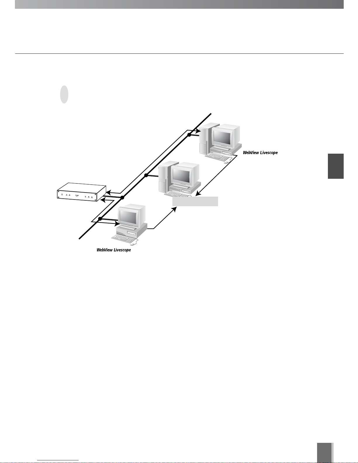
System Conf iguration
MV Manager and MV Station connect to camera servers via TCP/IP. Connections can also
be made over the Internet or an Intranet.
Introduction
7
MV Station
Monitoring
MV Manager
Creating monitoring screens/
Remote maintenance
Application Function
WebView Livescope
MV Manager
■ Application Types and Functions
WebView Livescope
MV Station
Lets users monitor images from several cameras from monitoring screens
created in MV Manager. Downloading, viewing and saving of pictures recorded
in the camera servers are also possible.
Transmits settings data such
as camera direction, zoom, etc.
Transmits camera
server settings and changes
ETHERNET
Lets users create and edit monitoring screens (MV data) to be used in MV
Station. Remote centralized control of several camera servers is also possible.
LAN
8
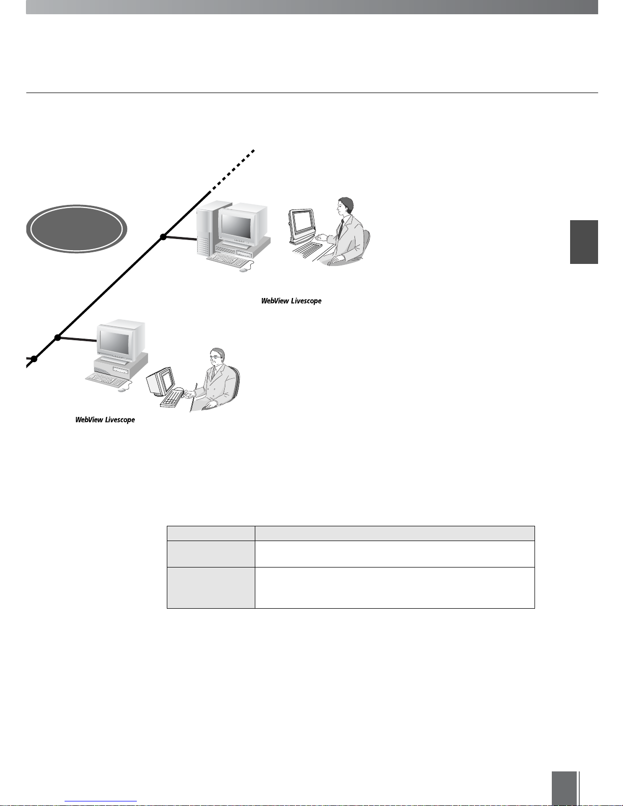
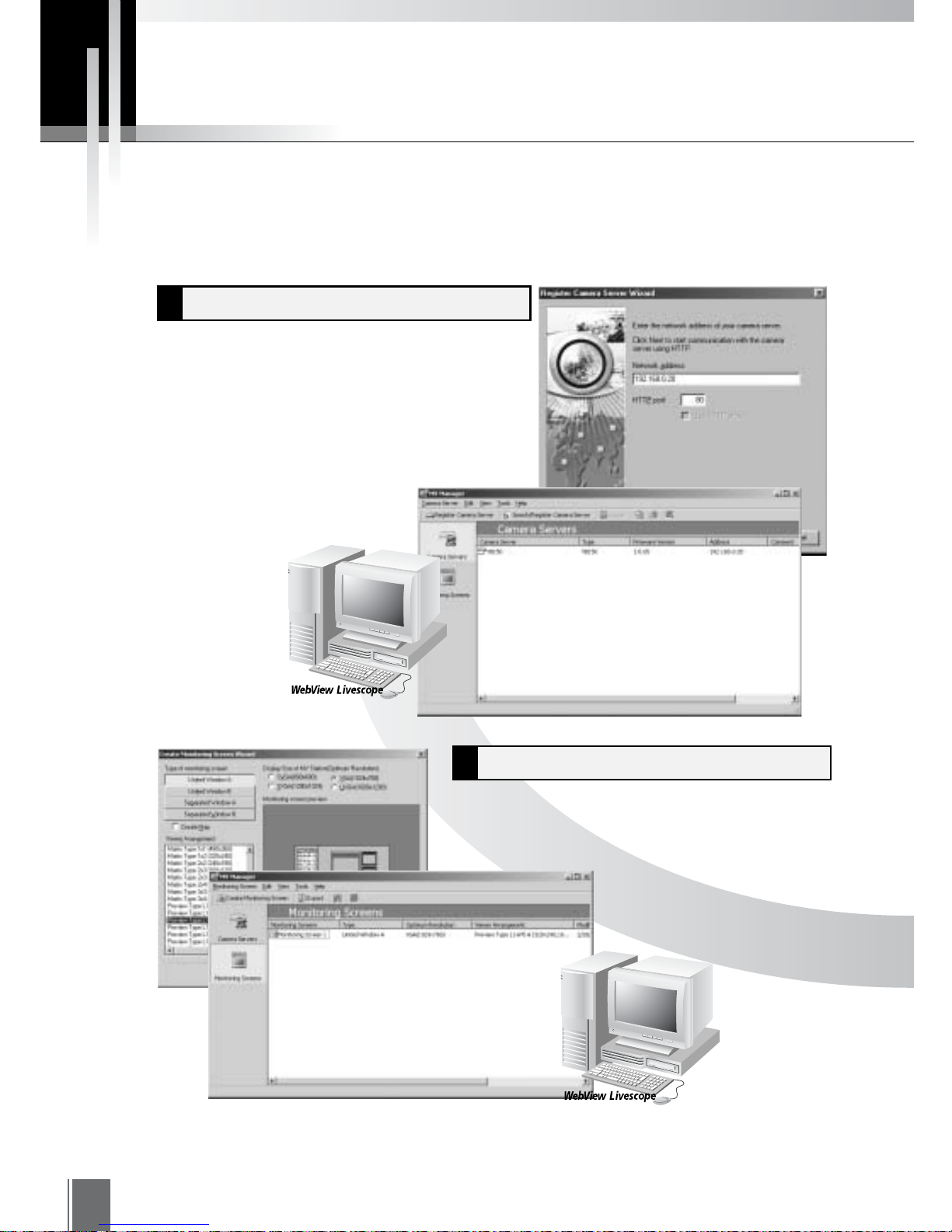
Tasks To Perform Prior To Monitoring
Registering Camera Servers1
Creating Monitoring Screens2
MV Manager
MV Manager
The first step is to register the camera servers.
The procedures in the wizard-style format
make the registration process very easy.
The wizard-style format is also used for creating
monitoring screens. Creating screens that suit your
application is very easy.
Before you can start monitoring, you need to perform the required settings as described in "Registering
Camera Servers" (Chapter 2), "Creating Monitoring Screens" (Chapter 3), and "Exporting MV Data"
(Chapter 4).
Introduction
9
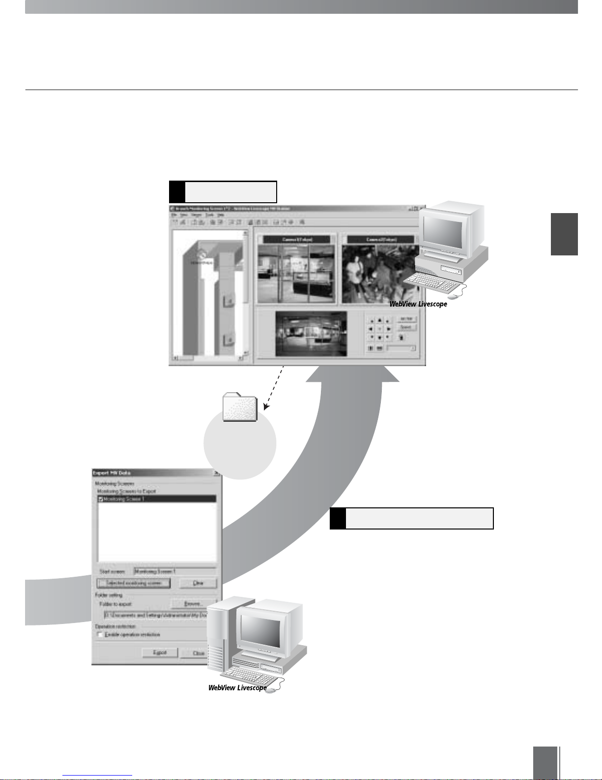
Monitoring4
Exporting MV Data3
MV Station
MV Manager
MV Data
folder
You must create an MV Data folder and
perform a task known as Exporting in order to
view images on the monitoring screen.
Monitoring is possible by accessing this MV
Data folder.

10
WebView Livescope MV Manager
WebView Livescope MV Station
CPU
Pentium III 600 MHz or better
Windows Me/ Windows 2000 (Service Pack 1 or later)/ Windows XP
Internet Explorer 5.0 or later required
Operating System
Web Browser
128 MB or better
Memory
Available space of 50 MB or better
Hard Disk
XGA (1024 × 768) or better with high-resolution 16-bit color display or better
Monitor
CPU
Pentium III 600 MHz or better
Windows Me/ Windows 2000 (Service Pack 1 or later)/ Windows XP
Internet Explorer 5.0 or later required
Operating System
Web Browser
128 MB or better
Memory
Available space of 50 MB or better
Hard Disk
SVGA (800 × 600) or better with high-resolution 16-bit color display or better
Monitor
When using VB101, upgrade the firmware to version 3.0. The firmware is
available for free at the following Web site:
http://www.canon.com/webview/
c
Note
Operating Environment

Chapter
1
Installing
First, you need to install WebView Livescope MV Manager and WebView
Livescope MV Station.
12
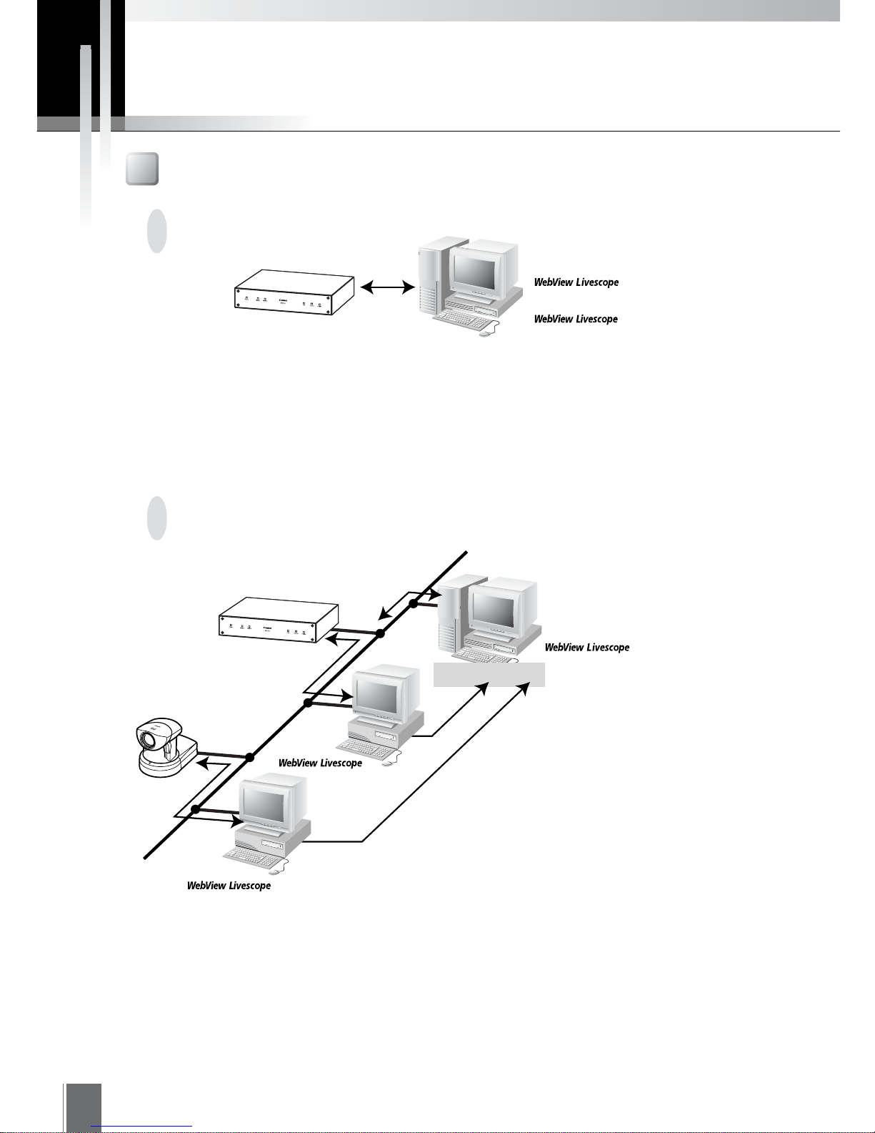
When Monitoring with One PC
When Using Several MV Stations
Install MV Manager. MV Station will also be installed automatically (see p. 15).
Install MV Manager in one PC and MV Station in several PCs. MV Manager exports information
for monitoring into the MV Data folder for MV Station to access. MV Station accesses the files
exported to this MV Data folder in order to display images from the cameras on the monitoring
screens.
MV Manager
Creating monitoring screens/
Remote maintenance
MV Station
Monitoring
VB150/VB101
Check the System Configuration
MV Manager
Creating monitoring screens/
Remote maintenance
MV Station
Monitoring
Receives videos
and controls
camera
File sharing
VB150/VB101
Refers to camera server information
and monitoring screen settings
Camera server
settings and changes
MV Data folder
MV Station
Monitoring
VB-C10
Prior to Installation...
Installing
1
13
If you want to access the MV Data folder from an environment (outside the same LAN) in which
it cannot be shared, place it and make it available in a file server where it can be accessed. In
this case, before starting installation, the PC in which the MV Data folder is to be placed must
be set so that the folder can be shared. Prepare a folder and set it to Share so that it can be
accessed over the network from the PC where MV Station is installed.
If several MV Stations are used and MV Data folders are placed in
locations other than the PC where MV Manager is installed
MV Manage
r
Creating monitoring
screens/Remote
maintenance
MV Station
Monitoring
Receives videos
and controls
c
amera
File sharing
VB150/VB101
Refers to camera server information
and monitoring screen settings
Exports camera server information
and monitoring screen settings
Camera server
settings and changes
MV Data folder
File server
14
Preparing the Computers
Installing the Camera Servers
First, you need to check your camera server. If the VB-C10/VB-C10R or VB150 is being used, there
is no need to upgrade the firmware. However, if the VB101 is being used, check that the firmware
version is 3.0 or later. See page 10 for details about the firmware upgrade.
Check to be sure the camera server has been correctly installed and that the initial settings
(network settings) have been made. Then connect to the network. You can perform detailed
settings or view tests from MV Manager. For procedures on installing and setting up the camera
server, please see the manual supplied with the camera server.
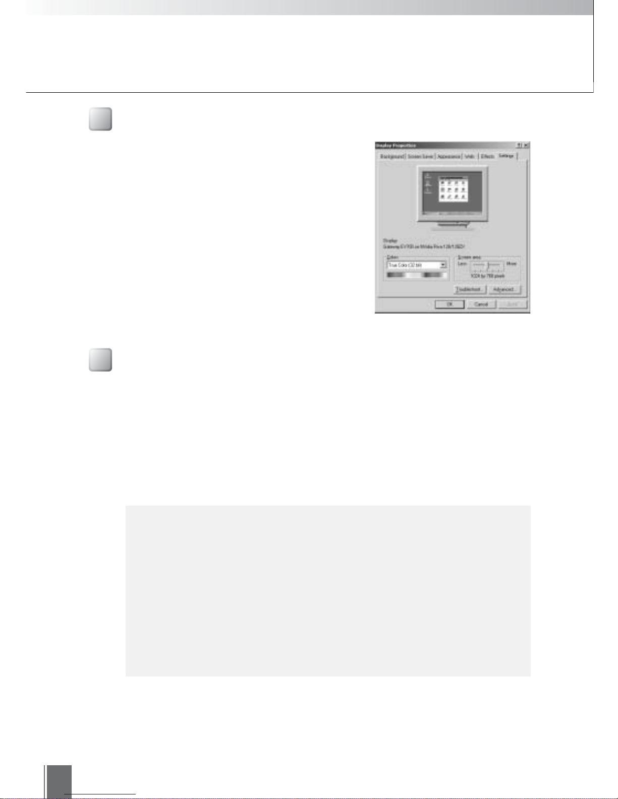
• At the PC where MV Manager is to be installed, set the
screen resolution to XGA (1024 × 768) or higher.
• At the PC where MV Station is to be installed, set the
screen resolution to SVGA (800 × 600) or higher. Be
sure the resolution that you set is the same or higher
than the optimum resolution of the monitoring screens
created in MV Manager (see p. 30).
Display Properties
c
Note
●"Maximum Number of Clients" must be set to five or more for the VB150 (or
VB101) and to two or more for the VB-C10/VB-C10R. To make settings for
the VB101, use the "Application Settings Page", and for the VB150 or VBC10/VB-C10R, use the "WebView Livescope Settings Page". While default
settings meet the above requirements, the settings must be checked if any
changes have been made.
●If a connection was made from MV Station via a proxy server, notification of
external device input (see p. 78), external device output control (see p. 79),
notification of motion detection (see p. 80) as well as the External Device
Input Log Viewer (see p. 98) will not work.
Prior to Installation...
Installing
1
15
Installation Procedures
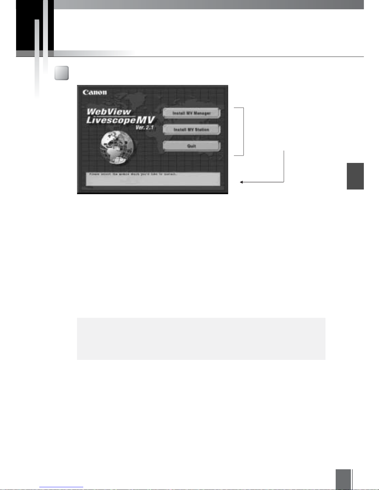
Starting Up the Installer
When you load the WebView Livescope MV Ver. 2.1 installer CD-ROM into the PC, the main
panel of the installer automatically appears. If it does not appear, in Explorer, double-click
"\mv2setup.exe" on the CD-ROM.
Click the buttons to start up the installer and proceed with installation.
● Install MV Manager
This button installs both MV Manager and MV Station. This setup is for administrators who manage the
camera servers and create monitoring screens.
● Install MV Station
This button installs MV Station only. This setup is for operators who view monitoring screens.
When you place the mouse
cursor on these buttons,
explanations about them appear
below the cursor.
c
Note
This product consists of MV Manager and MV Station for one client. If
additional MV Station installations are required, please purchase separate MV
Station licenses.
16
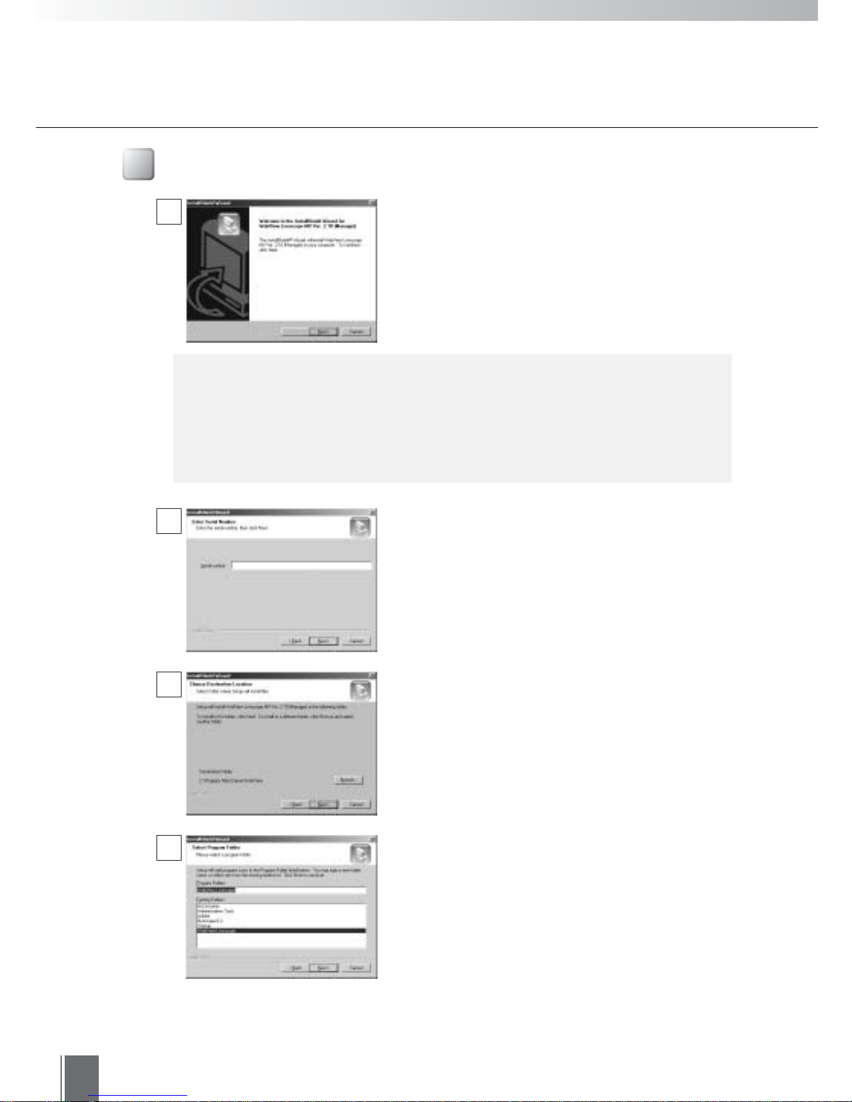
Installing MV Manager
When you click the Install MV Manager button on
the main panel, the installer starts up and the
process of installing MV Manager begins. Click Next
to continue the installation.
Enter the Serial number and click Next. The Serial
number is indicated on the seal attached outside the
software package.
A screen appears where you can specify a folder in
which MV Manager is to be installed.
To specify a folder other than the one indicated, click
Browse and select the folder you want.
When the folder has been specified, click Next.
c
Note
If you are installing WebView Livescope MV Ver. 2.1 into a PC in which Ver. 1.0
is already installed, information such as the camera servers and monitoring
screens that were registered and set with Ver. 1.0 cannot be used with Ver.
2.1. However, if Ver. 2.0 is installed, the information registered and set with
Ver. 2.0 can be used with Ver. 2.1.
Specify a name to be registered in the Program
menu under the Start menu, then click Next.
1
2
3
4
Installing
1
17
Installation Procedures
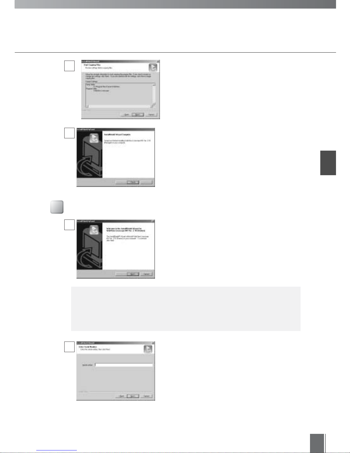
Check the items you have specified and selected
thus far, then click Next. The installation will be
performed by copying files and setting the registry.
When installation is complete, click Finish to exit the
installer.
Installing MV Station
When you click the Install MV Station button on the
main panel, the installer starts up and the process of
installing MV Station begins. Click Next to continue
the installation.
Enter the Serial number and click Next. The Serial
number is indicated on the seal attached outside the
software package.
c
Note
If you are installing WebView Livescope MV Ver. 2.1 into a PC in which Ver.
1.0 is already installed, information such as the work folders that were set
with Ver. 1.0 cannot be used with Ver. 2.1. However, if Ver. 2.0 is installed, the
information registered and set with Ver. 2.0 can be used with Ver. 2.1.
5
1
2
6
18
Installation Procedures
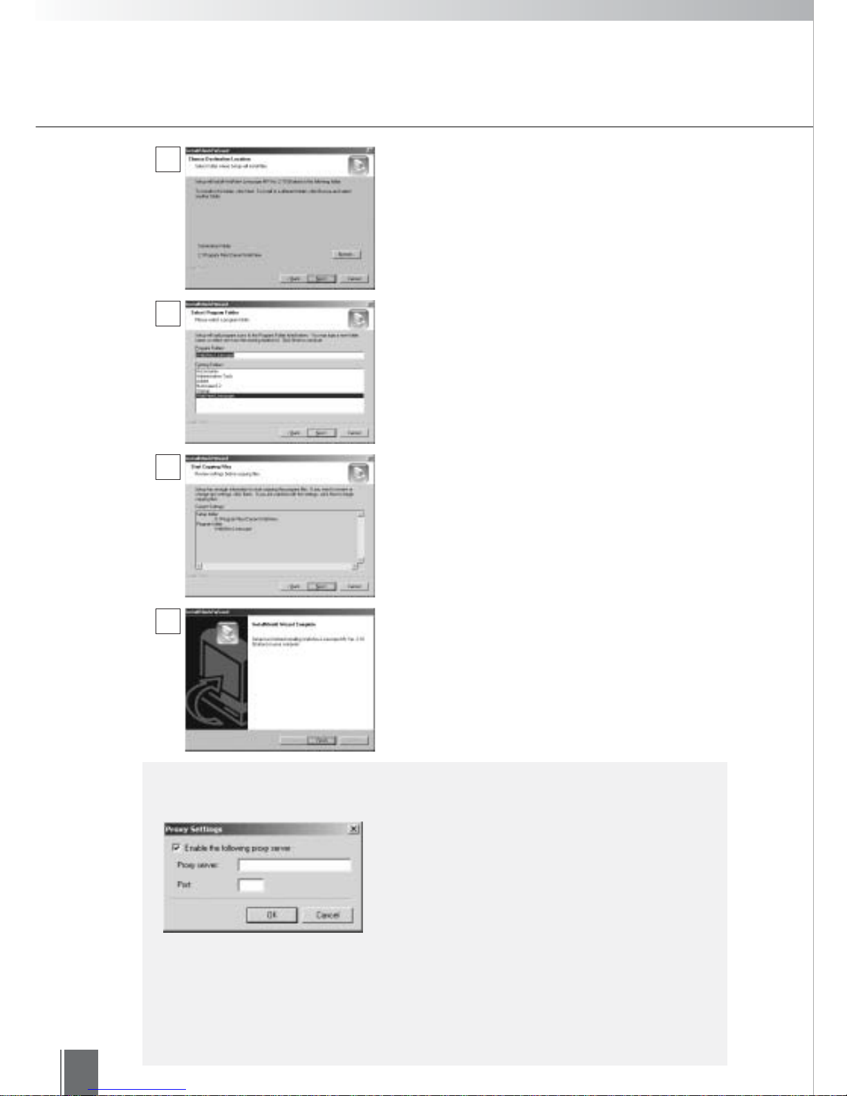
●After MV Manager and MV Station have been installed, make the following
settings if connections are to be made via a proxy server.
c
Note
To make proxy settings, in MV Manager, choose
Option from the Tools menu and click the "HTTP
proxy" button, and in MV Station, choose
Network from the Option menu and click the
HTTP Proxy button.
A screen appears where you can specify a folder in
which MV Station is to be installed.
To specify a folder other than the one indicated, click
Browse and select the folder you want.
When the folder has been specified, click Next.
Specify a name to be registered in the Program
menu under the Start menu, then click Next.
Check the items you have specified and selected
thus far, then click Next. The installation will be
performed by copying files and setting the registry.
When installation is complete, click Finish to exit the
installer.
3
4
5
6
●If you have changed the HTTP port number (normally it is 80) at the camera
server, select that camera server on MV Manager, click the Properties button
on the Toolbar and be sure to change the HTTP port number on the Network
tab (see p. 99). Since MV establishes an HTTP connection when it starts up,
you need to specify the HTTP port even when Auto-select or WV-TCP is
selected as the connection protocol.

Chapter
2
Registering Camera Servers
Next, WebView Livescope MV Manager is used to register and set camera
servers.
20
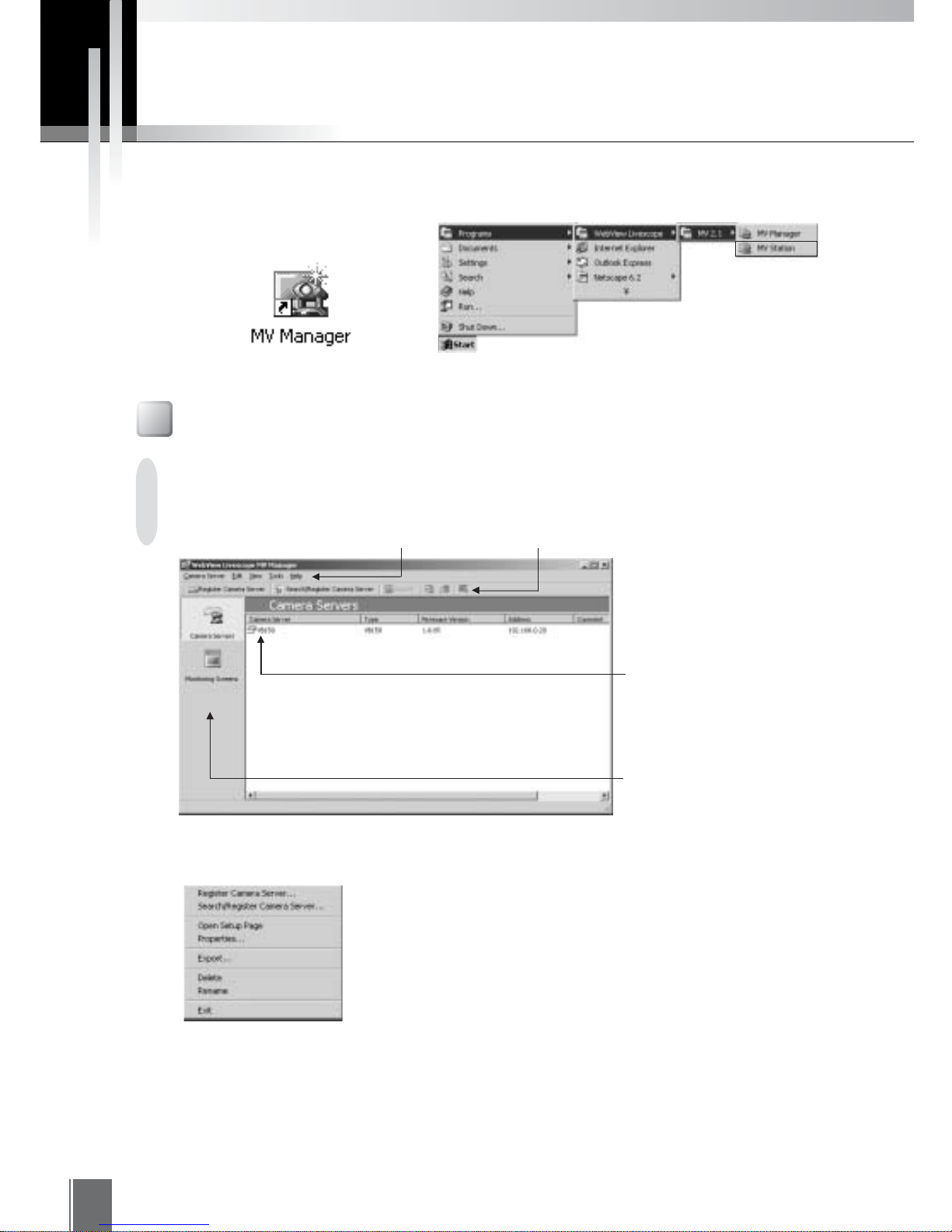
To register a camera server, first start up MV Manager. To start up MV Manager, double-click the desktop
icon or click the Start button and choose MV Manager from the Programs menu.
Screen Configuration
Starting up from the Start menu
This screen is used to add a camera server to be monitored or set a camera server.
"Camera Server"
An icon represents the
camera server that has been
created.
"Menu"
"
Toolbar
"
Menu
"Navigation bar"
Main window switches
between Camera Servers and
Monitoring Screens.
Starting up from the desktop icon
Camera Server
Camera Server
"Register Camera Server"
Starts up the wizard for registering a camera server.
"Search/Register Camera Server"
Auto searches camera servers and starts the wizard for registering a
camera server.
"Open Setup Page"
Opens the selected camera server’s settings page in the Web browser.
"Properties"
Displays the properties of the selected camera server.
"Export"
Exports MV data.
"Delete"
Deletes the selected camera server.
Registering Camera Servers
Registering Camera Servers
2
21
Toolbar
"Register Camera Server"
Starts up the wizard for registering a camera server.
"Search/Register Camera Server"
Auto searches camera servers and starts the wizard for registering a
camera server.
"Export"
Exports MV data.
"Open Setup Page"
Opens the selected camera server’s settings page in the Web browser.
"Properties"
Displays the properties of the selected camera server.
"View Test"
Conducts video tests.
"Rename"
Changes the name of the camera server.
"Exit"
Exits MV Manager.
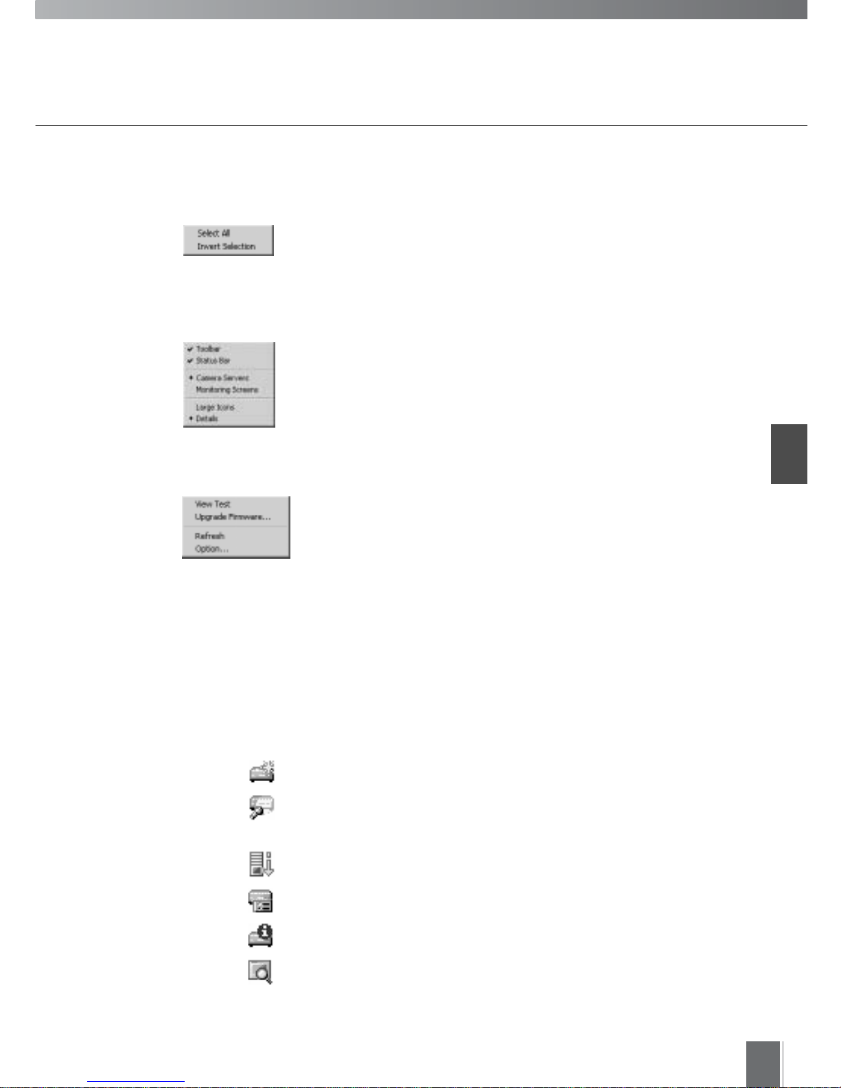
Edit
"Select All"
Selects all camera servers.
"Invert Selection"
Changes selection from selected camera servers to ones that are not
selected.
View
"Toolbar/Status Bar"
Shows or hides the Toolbar/Status Bar.
"Camera Servers/Monitoring Screens"
Switches between the camera server list and the monitoring screen
list.
"Large Icons/Details"
Changes icon display
Tools
"View Test"
Conducts video tests.
"Upgrade Firmware"
Upgrades camera server firmware. (for VB101 only)
"Refresh"
Updates displayed information to the latest information.
"Option"
Changes the selected camera server connection settings and the
export data settings.
22
Camera Server Registration W izards
The first task to perform in MV Manager is to register camera servers that are to be monitored. To add a
camera server, simply follow the easy instructions in the wizard-style screens. There are two wizards: the
Register Camera Server wizard, which is used to enter the network address for the camera server; and the
Search/Register Camera Server wizard, for auto detecting camera servers connected to the network.
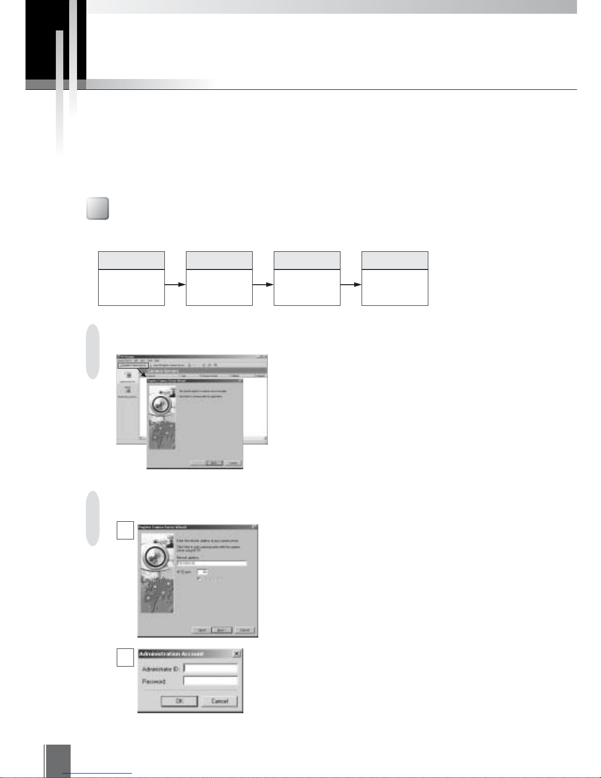
Select Camera Servers on the Navigation bar, and
click Register Camera Server on the Toolbar. When
the wizard startup screen appears, click Next.
In the "Network address" field, enter an IP address
or host name for the camera server being added.
The HTTP port number set as a property (see p. 99)
of the camera server appears as a default in the
HTTP port field. Although the HTTP port number is
usually 80, if another value is preferred, enter that in
the HTTP port field and click Next.
Step 1
Start up the
Register Camera
Server Wizard
Step 2
Enter a network
address for the
camera server
Step 3
Enter a name
and comment
for the camera
server
Step 4
Complete the
settings
Registering a Camera Server
Step 1: Start up the Register Camera Server Wizard
Camera servers are registered in the following 4 steps:
Step 2: Enter a network address for the camera server
1
2
Camera server information is retrieved at the
entered network address. Enter the Administrator ID
and Password in the window that appears, and click
OK.
Registering Camera Servers
2
23
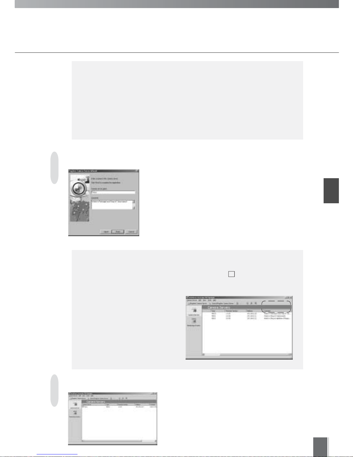
You can give the camera server any name you wish.
Enter the name in the "Camera server name" field.
This field cannot be left blank. It is also not possible to
give the same name to more than one camera server.
You can type any comment you wish for the camera
server in the Comment field. This comment is reflected in
"Comment" found in MV Manager, the monitoring screen
and other areas, and can be used for making
confirmations, etc. Several lines can be entered. It can also
be left blank. When finished with this screen, click Finish.
e
Tip
●The device name that was entered and set in the camera server’s settings page is
reflected in the "Camera server name" field as a default. If this setting was not
made, the network address that was entered in part of Step 2 is reflected as a
default instead. In the case of VB-C10/VB-C10R, the network address is reflected
from the beginning.
●Comments such as the
installation conditions of the
camera server, the position of
cameras connected to the
camera server, or the objects
being monitored are convenient
when several camera servers
and cameras are being
operated.
The camera server is registered.
When OK is clicked in Step 2, an error message appears in the following
cases (see p. 113 for details):
●MV Manager cannot connect to the camera server, because the camera
server is not correctly connected to the network, the power switch on the
camera server is not turned on, etc.
●The network address was not entered correctly (entry error).
●The camera server setting does not permit MV Manager to access it.
●The VB101 firmware has not been upgraded to Ver. 3.0.
e
Tip
Step 3: Enter a name and comment for the camera server
Step 4: Complete the settings
1
24
e
Tip
●Please conduct a view test (see p. 64) to check to be sure that the camera
server has been correctly set.
Adding more than one camera server
Up to 100 camera servers can be registered. To add more than one camera
server, repeat steps 1 through 4.
Deleting a camera server
To delete the registered camera server, select the camera server by clicking
on it, then choose Delete from the Camera Server menu. When the camera
server that was being used in the created monitoring screen is deleted, it is
also deleted from the monitoring screen at the same time, and there is a
possibility that displays will not appear correctly in the monitoring screen.
Registering Camera Servers
2
25
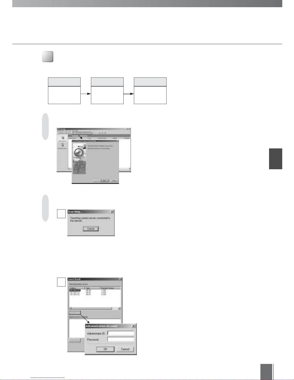
Click Search/Register Camera Server on the
Toolbar. When the wizard startup screen appears,
click Next.
Camera servers connected to the network are
automatically searched.
* If HTTP port other than 80 is used, the Search/
Register Camera Server feature will only be
available with the VB150. For other camera
servers, please use the Register Camera Server
registration procedure described on page 22.
Step 1
Start up the
Serch/Register
Camera Server
Wizard
Step 2
Search for and
register the
camera server
Step 3
Complete the
settings
Searching/Registering Camera Servers
Step 1: Start up the Serch/Register Camera Server Wizard
Camera servers are searched and registered in the following 3 steps:
Step 2: Search for and register the camera server
Camera Server Registration Wizards
1
2
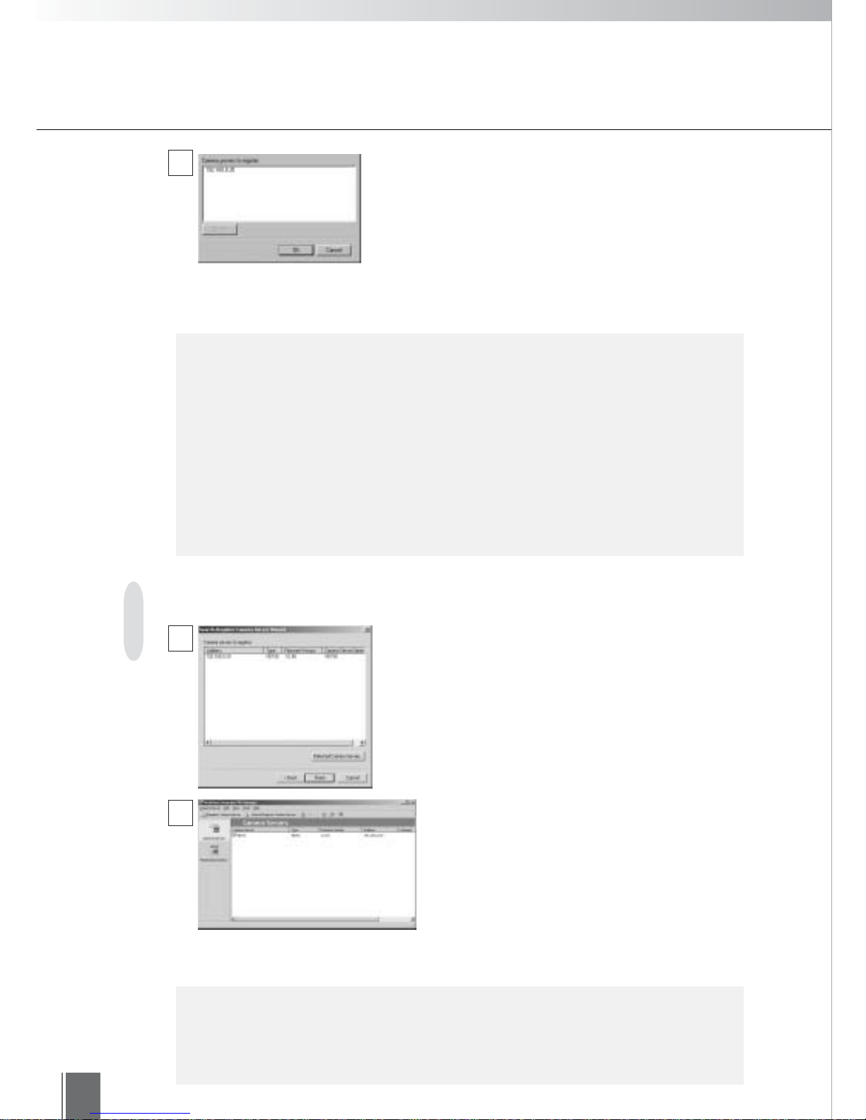
From the list of detected camera servers, select the
one you want to register by clicking on it, then click
the Register button. Enter the Administrator ID and
Password in the window that appears, then click OK.
26
Camera Server Registration Wizards
A dialog box for confirming camera servers to be
registered appears. If you are satisfied with the list,
click Finish to complete registration. If you click
"Detected Camera Servers", the screen returns to
Step 2.
Camera server search and registration is not possible in the following cases
in Step 2 or later:
●The camera server is not on the same LAN. (In this case, register the
camera server from "Register Camera Server". see p. 112.)
●MV Manager cannot connect to the camera server, because the camera
server is not correctly connected to the network, the power switch on the
camera server is not turned on, etc.
●The camera server setting does not permit MV Manager to access it.
●The VB101 firmware has not been upgraded to Ver. 3.0.
c
Note
Step 3: Complete the settings
1
2
The camera servers are automatically given names.
If you want to change a name, click the camera
server icon to select it, then right click on the
selection. When the pop-up menu appears, choose
"Rename". Alternatively, you can double-click on the
camera server icon to display the camera server’s
properties. Click the General tab and change the
name there.
e
Tip
●Please conduct a view test (see p. 64) to check to be sure that the camera
server has been correctly set.
●Up to 100 camera servers can be registered.
3
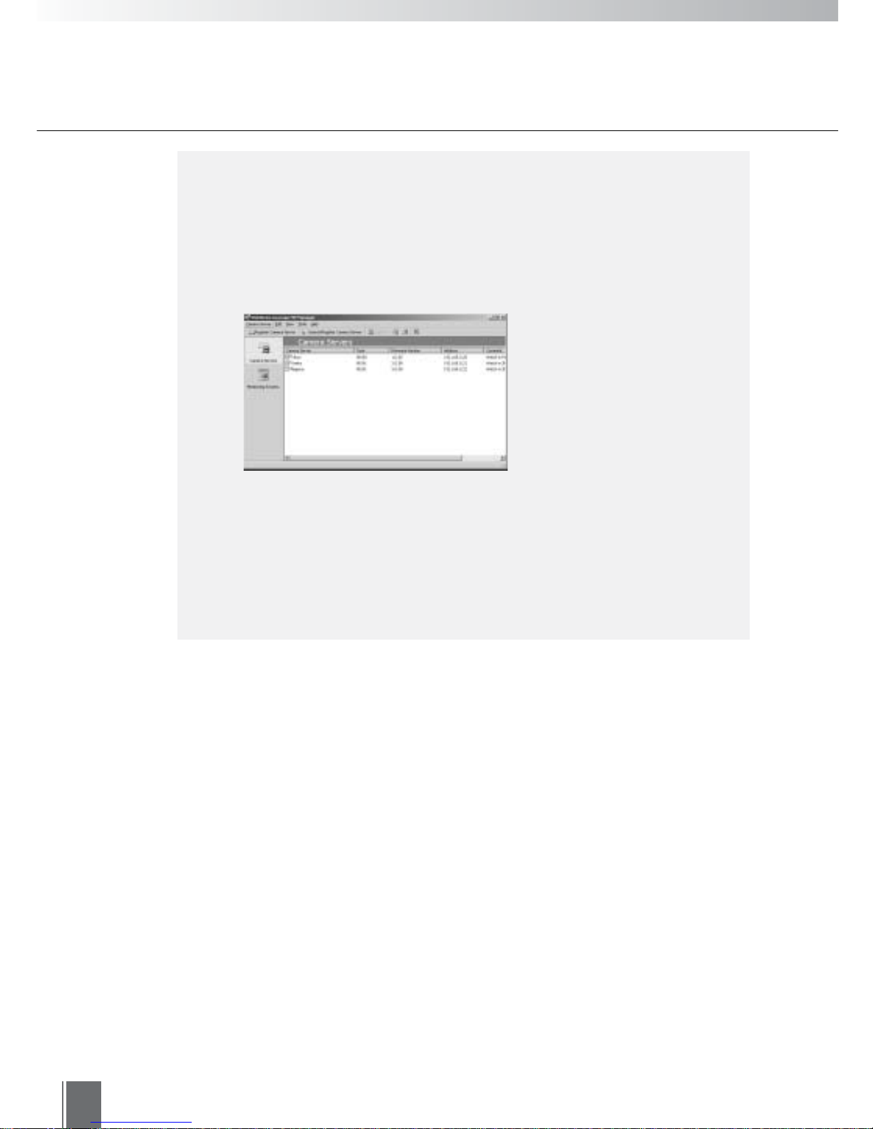
The camera server to be registered appears in the
space below. To register more than one camera
server, repeat the process of selecting a camera
server, clicking Register, and entering the
Administrator ID and Password for each camera
server you want to register. Camera servers with the
same Administrator ID and Password can be
selected in multiples and registered at one time.
When finished, click OK.

Chapter
3
Creating Monitoring Screens
Using WebView Livescope MV Manager to create monitoring screens
appropriate to your application.
28
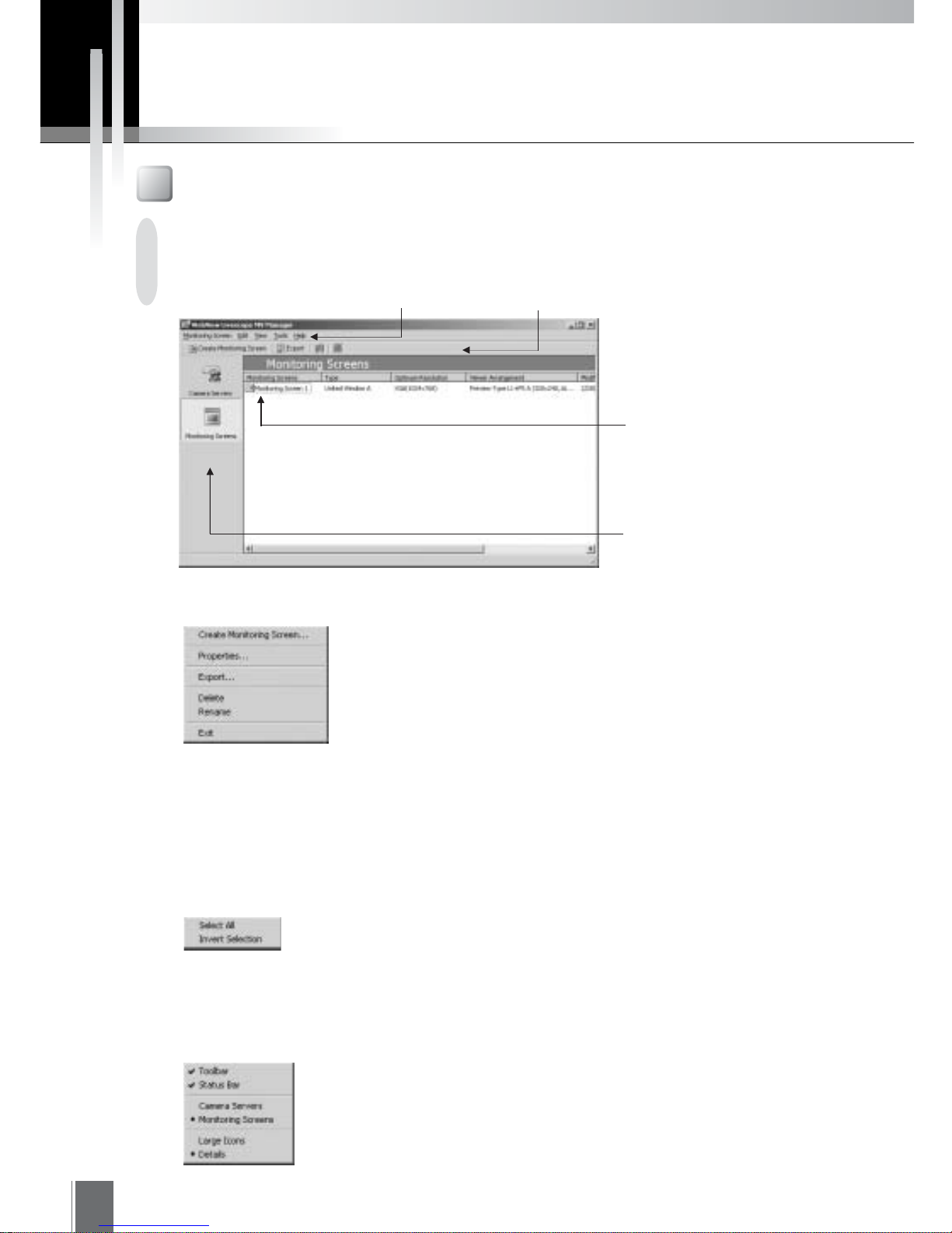
"Menu"
"Toolbar"
"Monitoring Screen"
An icon represents the
monitoring screen that has
been created.
This screen is used to create and edit monitoring screens.
Monitoring Screen
Menu
Monitoring Screen
"Create Monitoring Screen"
Starts up the wizard to create a monitoring screen.
"Properties"
Displays the properties of the selected monitoring screen.
"Export"
Exports MV Data.
"Delete"
Deletes the selected monitoring screen.
"Rename"
Changes the name of the monitoring screen.
"Exit"
Exits MV Manager.
Edit
"Select All"
Selects all monitoring screens.
"Invert Selection"
Changes selection from a selected monitoring screen to ones that are
not selected.
View
"Toolbar/Status Bar"
Shows or hides Toolbar/Status Bar.
"Camera Servers/Monitoring Screens"
Switches between the camera server list and the monitoring screen list.
"Large Icons/Details"
Changes icons display.
Screen Configuration
"Navigation Bar"
Main window can be switched
between Camera Servers and
Monitoring Screens.
Creating Monitoring Screens
Creating Monitoring Screens
3
29
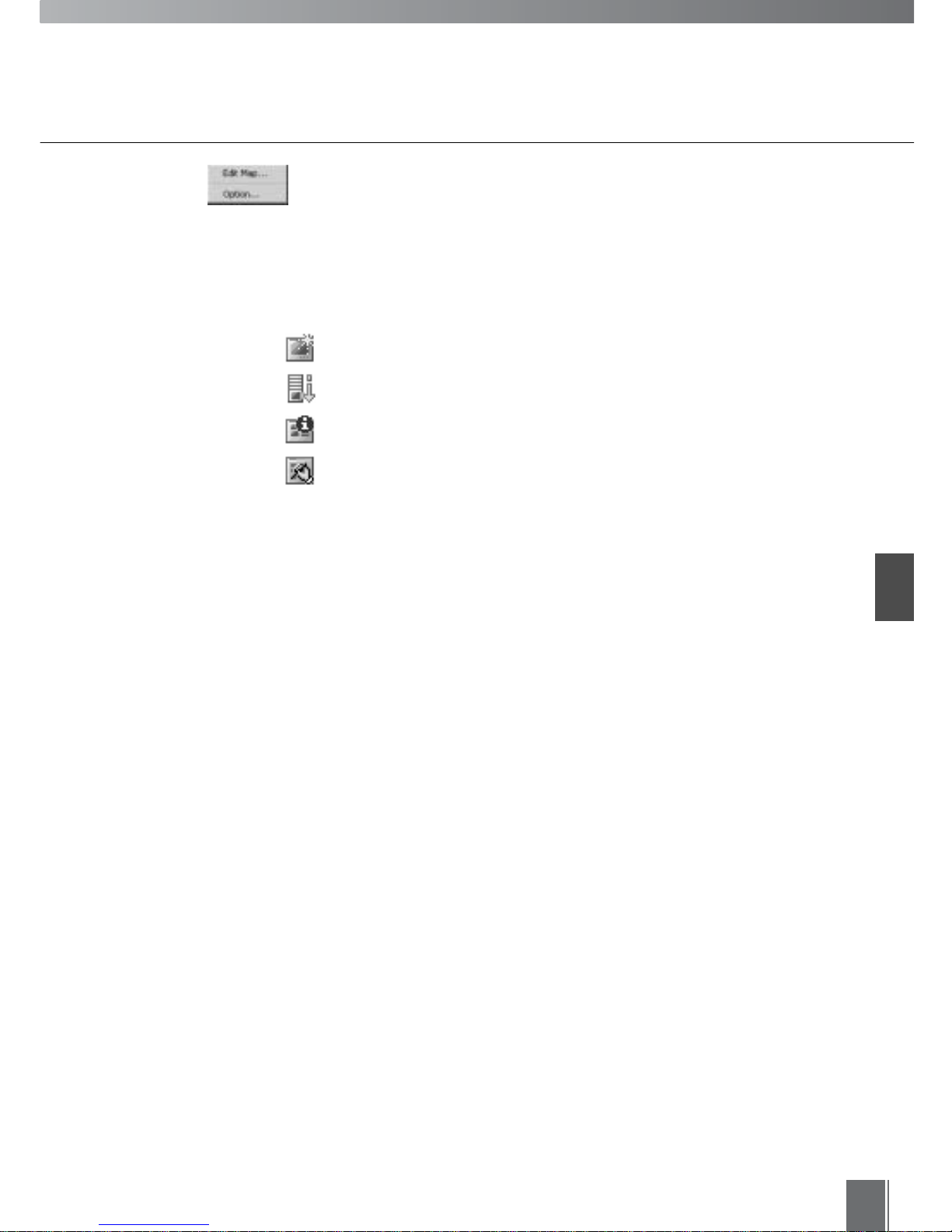
Toolbar
"Create Monitoring Screen"
Starts up the wizard to create a monitoring screen.
"Export"
Exports MV Data.
"Properties"
Displays the properties of the selected monitoring screen.
"Edit Map"
Lets you edit the map.
Tools
"Edit Map"
Lets you edit the map.
"Option"
Changes camera server connection settings and proxy settings.

30
Create Monitoring Screen Wizard
When you have finished registering the camera servers, the next task is to create monitoring screens.
Various monitoring screens can also be created easily by operating in accordance with directions from a
wizard screen. The five steps required are as follows:
Step 1:
Start up the
Create
Monitoring
Screen Wizard
Step 2:
Select a
monitoring
screen
Step 3:
Select cameras
Step 4:
Enter monitor-
ing screen
name and
comments
Select Monitoring Screens on the Navigation bar
and click Create Monitoring Screen on the Toolbar.
When the wizard startup screen appears, click Next.
Select a monitoring screen.
(1) Select one of the four types of monitoring screen
with the buttons at the top left (see p. 33).
(2) Select one of the four types of display sizes with
the radio buttons at the top right.
(3) Different combinations of monitoring screen type
and display size will cause the details shown in
the Viewer Arrangement box at the bottom left to
be changed. (For viewer arrangements, refer to
"Viewer Arrangements" on p. 34)
Step 5:
Complete the
settings
Step 1: Start up the Create Monitoring Screen Wizard
Step 2: Select a monitoring screen
Select "Type of monitoring screen"
and "Display Size of MV Station"
Display "Monitoring screen preview" by
selecting "Viewer Arrangement"
1
2
When you click a viewer arrangement, a sample
screen will appear in the "Monitoring screen
preview" window at the bottom right.
Here, we shall try creating a monitoring screen by
selecting "United Window A", "XGA(1024 × 768)",
"Preview Type L1 + P5A(320 × 240,160 × 120)".
Having made the selection, click Next to continue.
 Loading...