

Page 1
ENGLISH
Network Camera
Operation Guide
/
/
/
/
The Operation Guide should be read before using the network camera.
Page 2

Introduction
Thank you for purchasing a Canon Network Camera (hereafter referred to as the camera)*.
This “Operation Guide” explains the camera settings and operations. Read this guide carefully before using the camera to
ensure correct use. Also, be sure to read the files in the LICENSE folder on the Setup CD-ROM.
* The cameras described in this manual may include models not be sold in your country and region.
For the latest information on this product (firmware and included software, user manuals, operating environment, etc.),
please refer to the Canon Web Site.
Precautions for Use (Disclaimer)
Disclaimer
To the full extent permitted by laws and regulations, neither Canon Inc. nor any of its subsidiaries or affiliates shall be
responsible for any financial losses that may be incurred as a result of the loss of recorded information or images,
regardless of the internal or external cause of the loss.
EXCEPT AS SET FORTH IN THE LIMITED WARRANTY ACCOMPANYING THE CAMERA AND WITHOUT
DETRACTING FROM ANY RIGHTS A CONSUMER MAY BE ENTITLED TO, AND TO THE FULL EXTENT PERMITTED
BY LAWS AND REGULATIONS: (1) NEITHER CANON INC. NOR ANY OF ITS SUBSIDIARIES OR AFFILIATES MAKE
ANY WARRANTY OF ANY KIND, EXPRESS OR IMPLIED, WITH REGARD TO THE MATERIAL IN THIS MANUAL OR
WITH REGARD TO THE USE OF THE CAMERA INCLUDING, WITHOUT LIMITATION, IMPLIED WARRANTIES AS TO
MARKETABILITY, MERCHANTABILITY, FITNESS FOR A PARTICULAR PURPOSE OR USE, OR NONINFRINGEMENT AND (2) NEITHER CANON INC. NOR ANY OF ITS SUBSIDIARIES OR AFFILIATES SHALL BE
LIABLE FOR ANY DIRECT, INCIDENTAL, OR CONSEQUENTIAL DAMAGES OF ANY NATURE RESULTING FROM
THE USE OF THIS MATERIAL OR THE CAMERA.
Network Security
The user is responsible for the network security of this product and its use.
Take appropriate network security measures to avoid security breaches. To the full extent permitted by laws and
regulations, neither Canon Inc. nor any of its subsidiaries or affiliates shall be liable for any losses, direct, incidental
or consequential damages, or liabilities that may be incurred as a result of network security incidents such as
unauthorized accesses.
<Network Security Recommendations>
• Change the password of the camera periodically.
• Change the HTTP or HTTPS port number of the camera.
• Limit access to the camera by network devices.
Privacy and Publicity Rights Regarding the Use of Video/Audio
When using the camera (for video or audio), it is the full responsibility of the user to protect privacy and avoid any
violation of publicity rights. For example, obtaining consent to install the camera in advance if specific buildings or
rooms are to be monitored. Canon shall have no liability whatsoever in this regard.
Legal Notice
In some cases, camera monitoring may be prohibited by law or regulation, the details of which differ by country.
Before using the camera, check the laws or regulations of the country or region where the camera is used.
2
Page 3

Copyright
Videos, images or sounds recorded with your camera may not be utilized or published without consent of copyright
holders, if any, except in such a way as permitted for personal use under the relevant copyright law.
Use of Included RM-Lite Software
Flaws or other problems with RM-Lite may result in recording failure or destruction or loss of recorded data. Canon
shall have no liability whatsoever for any loss or damages incurred by the user as a result of such problems.
Product Parts Life
Movable parts of this product (e.g., pan/tilt mechanism) as well as its electronic components may require
replacement at an earlier period, according to where the product is installed, and how it is used.
Please refer to Canon’s web site, for a reference as to the lifespan of the parts, in relation to how the product is used.
License Agreement for Included Software
For information on the License Agreement for Included Software, refer to the following files in the BundledSoftware folder in
the Included Setup CD-ROM LICENSE folder.
Software Type File Name
Camera Management Tool
Camera Angle Setting Tool
(Used by VB-M641VE, VB-M640VE, VB-M641V, VB-M640V, VB-M741LE, VB-M740E)
Network Video Recording Software RM-Lite RM-Lite-E.txt
VBTools-E.txt
This product is licensed under AT&T patents for the MPEG-4 standard and may be used for encoding MPEG-4 compliant
video and/or decoding MPEG-4 compliant video that was encoded only (1) for a personal and non-commercial purpose or
(2) by a video provider licensed under the AT&T patents to provide MPEG-4 compliant video. No license is granted or
implied for any other use for MPEG-4 standard.
Trademarks
• Canon and the Canon logo are registered trademarks of Canon Inc.
• Microsoft, Windows, Windows Vista, Internet Explorer, Windows Server, Windows Media and ActiveX are trademarks or
registered trademarks of Microsoft Corporation in the United States and other countries.
• Windows is legally recognized as the Microsoft Windows Operating System.
• This product comes with exFAT, a licensed file system technology from Microsoft.
• QuickTime is a trademark of Apple Inc.
• SD, SDHC and SDXC logos are trademarks of SD-3C, LLC.
• All other company or product names used in this manual are trademarks or registered trademarks of their respective
holders.
Open Source Software
The product (camera and included RM-Lite) contains Open Source Software modules. For details, please refer to
“ThirdPartySoftware-E.pdf” (Third-Party Software License) in the Open-SourceSoftware folder in the LICENSE folder on the
Setup CD-ROM. Each module’s license conditions are also available in the same folder.
Software under GPL and LGPL
If you would like to obtain the source code under GPL/LGPL, please contact us at nvsossg@canon.co.jp and provide the
following information in English or Japanese:
1. Product name and firmware version.
3
Page 4

2. Name of the software module or modules you would like to obtain.
You can obtain the source code for a least three years from the day you purchased this product. Please note we may bill
you for any costs we incur in providing you the source code.
Security Export Control
This product is subject to security export control. Therefore, to export or carry it overseas may require an authorization by
governmental agencies.
4
Page 5

User Manuals
Types of User Manuals
The following describes the different camera user manuals.
Included User Manuals
Installation Guide
This describes precautions and procedures for installing the camera. Sections you should reference in this guide will be
marked “Installation Guide” along with the name of the reference items.
Guides Included on the Setup CD-ROM
Operation Guide (This Guide)
This document explains the initial camera settings, Viewer operations, Admin Tools settings, troubleshooting and other
operations.
Appendix – Specifications
This lists the camera specifications.
Camera Management Tool User Manual
This explains details on using the Camera Management Tool.
Network Video Recording Software RM Series Administrator Manual
This explains details on using the RM-Lite video recording software (P. 22).
Notes
1. Any unauthorized reproduction of this guide is prohibited.
2. The contents of this guide are subject to change without any prior notice.
3. This document has been prepared with the utmost attention to accuracy. If you have any comments, however,
please contact a Canon sales representative.
4. Canon shall assume no liability for any outcome of using this product, notwithstanding items 2 and 3 above.
How to Use This Operation Guide
The assumed reading format of this operation guide is on a computer screen.
Software Screenshots
The software screenshots samples shown in this guide are for illustration only. The screenshots may differ from the
actual screens displayed.
Most screenshots used with the explanations are from a Windows 8.1 computer connected to a VB-R11 network
camera.
The video size set selected for explanations is [1280 x 720 / 640 x 360 / 320 x 180]. If using a different video size set,
substitute those sizes.
5
Page 6
Symbols Indicating Camera Models
R11
R10
M641
M640
M741
M740
Symbols Indicating Camera Models
Explanations that differ depending on the camera model are indicated by the camera name and the following
symbols.
Symbol Camera Model
VB-R11VE, VB-R11
VB-R10VE
VB-M641VE, VB-M641V
VB-M640VE, VB-M640V
VB-M741LE
VB-M740E
Symbols Indicating Safety Precautions
This section explains the symbols used in this guide. The following symbols used in this guide indicate information for
safe use of the product, as well as important and supplemental information the user should know. Be sure to read and
understand this information when using the product.
Symbol Meaning
Warning
Caution
Caution
Important
Note
Failure to follow the instructions indicated by this symbol may result in death or serious
injury. Be sure to follow these warnings to ensure safety.
Failure to follow the instructions indicated by this symbol may result in injury. Be sure to
follow these precautions to ensure safety.
Failure to follow the instructions indicated by this symbol may result in property damage.
Be sure to follow these precautions.
Cautions and restrictions during operation. Make sure to read these carefully.
Supplementary descriptions and reference information.
6
Page 7
Safety Precautions
This section explains precautions that must be followed when using the camera.
If they are not followed, injury, death and/or property damage may occur. Read the following information carefully and be
sure to follow the precautions.
Important Warnings
Warning
To reduce a risk of fire or electric shock, do not expose this product to rain or moisture.
(VB-R11, VB-M641V, VB-M640V)
Caution
TO REDUCE THE RISK OF ELECTRIC SHOCK, DO NOT REMOVE COVER (OR BACK).
NO USER-SERVICEABLE PARTS INSIDE. REFER SERVICING TO QUALIFIED SERVICE PERSONNEL.
The AC adapter (sold separately) can be connected to the camera from a standard AC power outlet.
Please refer to the user manual to make sure that the camera is compatible with the adapter.
• The socket-outlet should be installed near the equipment and should be easily accessible.
• Unplug the equipment from the wall outlet before cleaning or maintaining.
FDA regulation
This Network Camera has not been evaluated by the Food and Drug Administration (FDA) for use as a medical
device. When incorporated into a system with medical applications, FDA regulations may apply. Therefore, please
consult your legal advisor to determine whether FDA regulations apply.
FCC REGULATIONS
Network Camera, Model Name: VB-R11VE/VB-R10VE/VB-M641VE/VB-M640VE/VB-M741LE/VB-M740E
This equipment has been tested and found to comply with the limits for a Class A digital device, pursuant to Part 15
of the FCC Rules.
These limits are designed to provide reasonable protection against harmful interference when the equipment is
operated in a commercial environment. This equipment generates, uses, and can radiate radio frequency energy
and, if not installed and used in accordance with the user manual, may cause harmful interference to radio
communications. Operation of this equipment in a residential area is likely to cause harmful interference in which
case the user will be required to correct the interference at his own expense.
Do not make any changes or modifications to the equipment unless otherwise specified in the manual. If such
changes or modifications should be made, you could be required to stop operation of the equipment. Use of
shielded cable is required to comply with class A limits in Subpart B of Part 15 of FCC Rules.
European Union regulatory notices:
Network Camera, Model Name: VB-R11VE/VB-R10VE/VB-M641VE/VB-M640VE/VB-M741LE/VB-M740E
Warning
This is a class A product. In a domestic environment this product may cause radio interference in which case the
user may be required to take adequate measures.
7
Page 8
FCC NOTICE
Network Camera, Model Name: VB-R11/VB-M641V/VB-M640V
This device complies with Part 15 of the FCC Rules. Operation is subject to the following two conditions: (1) This
device may not cause harmful interference, and (2) this device must accept any interference received, including
interference that may cause undesired operation.
Note: This equipment has been tested and found to comply with the limits for a Class B digital device, pursuant to
Part 15 of the FCC Rules. These limits are designed to provide reasonable protection against harmful interference in
a residential installation.
This equipment generates, uses and can radiate radio frequency energy and, if not installed and used in
accordance with the instructions, may cause harmful interference to radio communications.
However, there is no guarantee that interference will not occur in a particular installation. If this equipment does
cause harmful interference to radio or television reception, which can be determined by turning the equipment off
and on, the user is encouraged to try to correct the interference by one or more of the following measures:
• Reorient or relocate the receiving antenna.
• Increase the separation between the equipment and receiver.
• Connect the equipment to an outlet on a circuit different from that to which the receiver is connected.
• Consult the dealer or an experienced radio/TV technician for help.
Do not make any changes or modifications to the equipment unless otherwise specified in the manual. If such
changes or modifications should be made, you could be required to stop operation of the equipment.
Canon U.S.A., Inc.
One Canon Park, Melville, New York 11747, U.S.A.
Tel No. 1-800-OK-CANON (1-800-652-2666)
Precautions
Camera Precautions
Warning
If you notice abnormal conditions, such as smoke, unusual sounds, heat or strange odors, immediately stop using
the camera and contact your nearest dealer.
Fire or electric shock may result from continued use.
The following may result in fire or electric shock.
• If thunder starts, stop installation or inspection etc. and do not touch the camera or continue connecting the cable.
• Do not disassemble or modify the camera.
• Spray the camera with water, or otherwise make it wet (VB-R11/VB-M641V/VB-M640V).
• Please do not insert objects like water or metal objects within the camera housing.
• Do not use flammable sprays near the camera.
• Do not leave LAN cables, external power supplies or AC adapter (sold separately) power connectors connected
when the camera is not in use for long periods.
• Do not damage the connecting cable.
This camera should not be used with medical devices or other life-support systems.
Depending on the computer and network environment, high-precision video transmission cannot be guaranteed due
to video lag or loss.
Canon will assume no liability for any accident or damage resulting from use of the camera under the conditions
above.
8
Page 9
M741
R11 R10
M641 M640
M640
M741
Caution
Avoid looking directly at the infrared illumination at close distance for long periods of time.
Intense infrared illumination can cause eye damage.
Caution
The following may result in camera malfunction.
• Do not capture the sun, halogen lamps, and other very bright light sources or subjects.
• Do not expose the camera to strong impact or vibration.
• Do not forcibly turn the rotating parts of the camera by hand.
Camera Angle Setting Tool Precautions
Caution
The Camera Angle Setting Tool is for use when installing the camera. Do not use on a daily basis.
Frequent use may result in camera malfunction.
M641
Precautions for Built-In Camera Functions and Included Software
Caution
Do not use the following built-in camera functions or included software in situations requiring high reliability:
– Intelligent Function
– Image Stabilization Function
– Network Video Recording Software RM-Lite
These do not guarantee high-precision capture and cannot support applications beyond their intended range of use.
Canon will assume no liability for any accident or damage resulting from the use of these functions or software.
Maintenance Precautions
Warning
Do not use flammable solvents such as alcohol, paint thinner or benzine when cleaning the camera.
Use of these may result in fire or electric shock.
M740
Caution
Periodically inspect the parts and screws for rust and loosening.
For inspections, please contact the dealer where you purchased the product.
Failure to follow these precautions could result in injuries and equipment damage due to falling items.
Clean the Camera
Turn off the power before cleaning the camera.
Clean the Exterior
1 Dampen a soft cloth with water or diluted neutral detergent and gently wipe away any grime.
2 Wipe with a dry cloth.
9
Page 10

Important
Grime on the front cover and dome cover, may result in focusing problems, and or reduction of image quality. It is recommended
that the cover be cleaned on a regular basis.
Clean the Lens
Use a commercial lens cleaner to remove grime on the lens surface.
• Scratches on the lens surface may result in poor video capture.
• Auto focus functionality may be degraded if the lens surface is dusty or dirty.
Camera Disposal
Dispose of the camera in accordance with local laws and regulations.
10
Page 11

Table of Contents
Introduction...................................................................................................................... 2
Precautions for Use (Disclaimer) ............................................................................................ 2
License Agreement for Included Software ............................................................................. 3
Trademarks ............................................................................................................................. 3
Open Source Software............................................................................................................3
Security Export Control ........................................................................................................... 4
User Manuals................................................................................................................... 5
Types of User Manuals ...........................................................................................................5
How to Use This Operation Guide .......................................................................................... 5
Symbols Indicating Camera Models....................................................................................... 6
Safety Precautions........................................................................................................... 7
Precautions ............................................................................................................................. 8
Clean the Camera ................................................................................................................... 9
Camera Disposal .................................................................................................................. 10
Chapter 1 Before Use
Network Camera Capabilities........................................................................................ 20
Camera Software ........................................................................................................... 21
Software Included on the Camera ........................................................................................ 21
Software Included on the Setup CD-ROM ............................................................................ 21
Additional Software/Licenses (Sold Separately)................................................................... 23
Operating Environment.................................................................................................. 24
Camera Angle Setting Tool, Admin Viewer/VB Viewer, Admin Tools ................................... 24
Steps for Setting Up Camera......................................................................................... 25
Step 1 Pre-Installation Preparations...................................................................................... 25
Step 2 Check Camera Connection ....................................................................................... 25
Step 3 Install the Camera...................................................................................................... 25
Step 4 Set the Camera Angle .............................................................................................. 25
Step 5 Adjust Advanced Settings According to Use............................................................ 26
Step 6 Use the Viewers......................................................................................................... 26
Step 7 Use Admin Tools ....................................................................................................... 26
Troubleshooting .................................................................................................................... 26
Chapter 2 Camera Setup
Install Software .............................................................................................................. 28
Necessary Software..............................................................................................................28
Software Installation.............................................................................................................. 28
Check/Make Security Settings....................................................................................... 31
Check Firewall Settings.........................................................................................................31
Register the Camera IP Address as a Trusted Site .............................................................. 32
Settings When Using Windows Server.................................................................................. 33
Making Initial Camera Settings ...................................................................................... 36
Launch the Camera Management Tool ................................................................................ 36
Searching for Cameras and Setting up Networks ................................................................ 36
11
Page 12

Set the Password, Date and Time, Camera Name and Video.............................................. 38
Registering Camera’s IP Address to Trusted Sites............................................................... 40
Access the Top Page of the Camera to Check Video................................................... 41
Access the Top Page from Camera Management Tool........................................................ 41
Top Page............................................................................................................................... 41
Checking Camera Video....................................................................................................... 43
Chapter 3 Camera Angle Setting Tool
Launch the Camera Angle Setting Tool and Connect to a Camera .............................. 46
Launch the Camera Angle Setting Tool ................................................................................ 46
Connect to the Camera......................................................................................................... 46
Disconnect from the Camera and Close the Software.......................................................... 49
Camera Angle Setting Tool Screen ............................................................................... 51
Set the Camera Angle ................................................................................................... 53
Set the Camera Angle and Zoom ......................................................................................... 53
Set the Focus and Exposure Compensation ........................................................................ 54
Use a Camera Specification File ................................................................................... 56
Create a Camera Specification File ...................................................................................... 56
Chapter 4 Setting Page
How to Use The Setting Page........................................................................................ 60
Access the Setting Page....................................................................................................... 60
Common Setting Page Operations ....................................................................................... 61
About Each Setting Page...................................................................................................... 62
Configure Network Settings
[Basic Settings] > [Network] .................................................................................... 64
LAN ....................................................................................................................................... 64
IPv4 ....................................................................................................................................... 64
IPv6 ....................................................................................................................................... 65
DNS....................................................................................................................................... 66
mDNS.................................................................................................................................... 67
Set the Administrator Password
[Basic Settings] > [Password] ................................................................................. 68
Administrator Password........................................................................................................ 68
Set the Date/Time
[Basic Settings] > [Date and Time].......................................................................... 69
Current Date and Time.......................................................................................................... 69
Setting................................................................................................................................... 69
12
Set Video Size and Quality
[Basic Settings] > [Video Settings] .......................................................................... 72
All Videos .............................................................................................................................. 72
JPEG ..................................................................................................................................... 72
H.264(1) ................................................................................................................................ 73
H.264(2) ................................................................................................................................ 74
Set General Camera Controls
[Camera] > [Camera Settings]................................................................................. 75
Camera Name....................................................................................................................... 75
Page 13

Camera Control..................................................................................................................... 75
Day/Night (When Auto Is Set) ............................................................................................... 77
Installation Conditions........................................................................................................... 77
Camera Position Control ....................................................................................................... 78
External Input Device 1, 2 .................................................................................................. 78
External Output Device 1, 2 ............................................................................................... 78
Set Initial Video Settings
[Camera] > [Initial Setting]....................................................................................... 79
Initial Setting.......................................................................................................................... 79
Reduce Data Size by Lowering Video Quality in Specific Areas
[Video and Audio] > [ADSR].................................................................................... 82
Specified Area ...................................................................................................................... 82
ADSR..................................................................................................................................... 84
Display Date, Time and Text on the Viewer
[Video and Audio] > [On-screen display] ................................................................ 85
On-Screen Display................................................................................................................ 85
Set Audio Input/Output
[Video and Audio] > [Audio Settings] ...................................................................... 87
General Sound ...................................................................................................................... 87
Sound Clip Upload1to 3........................................................................................................ 88
HTTP, SNMP and FTP Server Settings
[Server] > [Server Settings] ..................................................................................... 89
HTTP Server.......................................................................................................................... 89
SNMP Server......................................................................................................................... 89
FTP Server............................................................................................................................. 90
WS-Security........................................................................................................................... 90
Video Transmission Settings
[Server] > [Video Server] ......................................................................................... 91
Audio Transmission/Reception Settings
[Server] > [Audio Server] ......................................................................................... 92
RTP Settings
[Server] > [RTP Server]............................................................................................ 93
RTP Server ............................................................................................................................ 93
Audio Multicast ................................................................................................................... 93
RTP Streaming 1 to 5 ............................................................................................................94
HTTP and FTP Upload Settings
[Video Record] > [Upload] ...................................................................................... 96
Video Record Setting............................................................................................................96
General Upload..................................................................................................................... 96
HTTP Upload......................................................................................................................... 97
FTP Upload ........................................................................................................................... 99
Settings for Recording Video to a Memory Card
[Video Record] > [Memory Card] .......................................................................... 101
Video Record Setting.......................................................................................................... 101
Memory Card Operations ................................................................................................... 101
Memory Card Information ................................................................................................... 101
13
Page 14

Set E-mail Notification
[Video Record] > [E-mail Notification] ................................................................... 102
E-mail Notification ............................................................................................................... 102
External Device Input Triggered Operation Settings
[Event] > [External Device] ................................................................................... 104
External Device Output 1, 2................................................................................................ 104
External Device Input.......................................................................................................... 104
External Device Input 1, 2................................................................................................... 105
Abnormal Audio Input Triggered Operation Settings
[Event] > [Audio Detection] ................................................................................... 107
Volume Detection................................................................................................................107
Scream Detection ............................................................................................................... 108
Timer Triggered Operation Settings
[Event] > [Timer] .................................................................................................... 110
Timer 1 to 4 ......................................................................................................................... 110
Execute Presets When Switching Day/Night Mode
[Event] > [Switch Day/Night].................................................................................. 112
Use Event Combinations
[Event] > [Linked Event] ........................................................................................ 113
Linked Event 1 to 4 .............................................................................................................113
Linked Event Operation Examples...................................................................................... 115
Set Users Who Connect to the Camera
[Security] > [User Restrictions] .............................................................................. 118
Authorized User Account.................................................................................................... 118
User Authority ..................................................................................................................... 118
Set Access Restrictions
[Security] > [Host Access Restrictions] ................................................................. 119
IPv4 Host Access Restrictions ............................................................................................ 119
IPv6 Host Access Restrictions ............................................................................................ 120
Set HTTP Communication Encryption
[Security] > [SSL/TLS]............................................................................................ 121
Certificates.......................................................................................................................... 121
Certificate Management...................................................................................................... 122
Encrypted Communications................................................................................................ 123
Network Port Authentication Settings
[Security] > [802.1X] .............................................................................................. 124
802.1X Authentication......................................................................................................... 124
Authentication Method........................................................................................................ 124
Set IPsec
[Security] > [IPsec] ................................................................................................ 126
IPsec ................................................................................................................................... 126
Auto Key Exchange Settings .............................................................................................. 126
IPsec Set 1 to 5 ................................................................................................................... 127
14
Memory Card Operations and Information Display
[Memory Card] ....................................................................................................... 130
Video Record Setting.......................................................................................................... 130
Page 15

Memory Card Operations ................................................................................................... 130
Memory Card Information ................................................................................................... 132
Display Camera Device Information and Perform Maintenance [Maintenance] ......... 134
Device Information..............................................................................................................134
Tool ..................................................................................................................................... 134
Chapter 5 Admin Viewer/VB Viewer
Admin Viewer and VB Viewer ...................................................................................... 138
Major Differences Between the Admin Viewer and the VB Viewer ..................................... 138
Viewer Access Restrictions................................................................................................. 138
View Video With Admin Viewer .................................................................................... 140
Launch the Admin Viewer ................................................................................................... 140
Admin Viewer/VB Viewer Screen ........................................................................................ 141
Check Information...............................................................................................................143
Change the Video Size and Display Screen Size ............................................................... 143
Operate the Camera With Admin Viewer..................................................................... 147
Obtain Camera Control Privileges ...................................................................................... 147
Use Pan/Tilt/Zoom...............................................................................................................147
Magnify and Display Part of Video (Viewer PTZ)................................................................ 151
Cropping and Displaying Part of an Image (Digital PTZ) ................................................... 153
Using Presets or the Home Position ................................................................................... 154
Use Backlight Compensation ............................................................................................. 155
Receive/Transmit Audio .................................................................................................... 155
Use Control for Admin ................................................................................................. 158
Control for Admin Panel ...................................................................................................... 158
Pan / Tilt / Zoom ................................................................................................................. 159
Preset / Initial Setting Registration ...................................................................................... 159
Smart Shade Control........................................................................................................... 159
Haze Compensation ........................................................................................................... 160
Focus .................................................................................................................................. 161
Exposure ............................................................................................................................. 162
White Balance..................................................................................................................... 164
Day/Night ............................................................................................................................ 165
Infrared .............................................................................................................................. 167
External Device Output ..................................................................................................... 167
Image Quality Adjustment................................................................................................... 168
Video Reception.................................................................................................................. 168
About Presets .............................................................................................................. 169
Register Presets .......................................................................................................... 170
Display the Preset Setting Panel......................................................................................... 170
Use [Quick Registration]..................................................................................................... 172
Register with [Advanced Preset Settings] Panel ................................................................ 173
Context Menu...................................................................................................................... 175
Change Multiple Presets Simultaneously............................................................................ 176
Automatically Move to a Preset Position at a Specified Time
(Auto Control Settings) ........................................................................................... 177
Configure [Auto Control Settings] ....................................................................................... 177
15
Page 16

Configure the Preset Tour Route ................................................................................. 179
[Tour Route Settings] Tab................................................................................................... 179
Tour Route Settings.............................................................................................................181
Context Menu...................................................................................................................... 183
Check the Event Detection Status With Admin Viewer................................................ 184
Confirm Status With the Event Display Panel...................................................................... 184
Record Snapshots/Video With Admin Viewer.............................................................. 186
Capture a Snapshot............................................................................................................ 186
Record Video to a Memory Card Manually......................................................................... 186
Use VB Viewer ............................................................................................................. 188
Launch VB Viewer and Differences with Admin Viewer...................................................... 188
Chapter 6 Admin Tools
Admin Tools Overview ................................................................................................. 192
Overview of Each Tool in the Admin Tools ......................................................................... 192
Access Admin Tools .................................................................................................... 193
Launch Admin Tools ........................................................................................................... 193
Admin Tools Operations Common to All Tools ................................................................... 194
Privacy Mask Setting Tool ........................................................................................... 196
Register Privacy Masks....................................................................................................... 196
Change/Delete a Privacy Mask........................................................................................... 198
Panorama Creation Tool .............................................................................................. 201
Create a Panorama Image.................................................................................................. 201
Delete a Panorama Image from the Camera ...................................................................... 204
Save/Load Panorama Image File........................................................................................ 204
View Restriction Setting Tool ...................................................................................... 206
Configure View Restrictions ................................................................................................ 206
Intelligent Function Setting Tool Overview .................................................................. 210
Intelligent Function.............................................................................................................. 210
Notes on Intelligent Function Settings and Operations ...................................................... 213
Pre-register Presets ..........................................................................................................214
Select the Intelligent Function Operation Mode ................................................................ 214
Intelligent Function Setting Tool
- Video Detection - ................................................................................................ 216
Steps for Configuring Video Detection ............................................................................... 216
Configure Detection Criteria ([Detection Criteria] Tab) ...................................................... 219
Configure Operations for Triggered Detection ([Event] Tab) ............................................. 227
Reduce Effects of Lighting Change (Detections Settings) ................................................. 228
Context Menu...................................................................................................................... 229
Intelligent Function Setting Tool
- Auto Tracking - .................................................................................................... 230
Set Auto Tracking................................................................................................................ 230
Auto Tracking Termination.................................................................................................. 233
Disable Auto Tracking......................................................................................................... 233
16
Intelligent Function Setting Tool
Display Options and Shared Operations .............................................................. 234
Display Event Status ........................................................................................................... 234
Page 17

Display Settings for Detection Areas/Detection Lines, Detection Results
(Display Options)............................................................................................................ 234
Restart Intelligent Function ................................................................................................. 235
Log Viewer................................................................................................................... 236
Download Log Files ............................................................................................................ 236
View Logs............................................................................................................................ 237
Recorded Video Utility................................................................................................. 240
Use the Video List............................................................................................................... 240
Download/Delete Video ...................................................................................................... 242
Play Back Video .................................................................................................................. 244
Chapter 7 Appendix
Memory Card Data ...................................................................................................... 250
Saved Data and Data Organization of Memory Card ......................................................... 250
Data Downloaded with Recorded Video Utility................................................................... 250
Modifiers ...................................................................................................................... 252
Troubleshooting........................................................................................................... 254
List of Log Messages .................................................................................................. 256
Log Messages on the Camera............................................................................................ 256
Error Log ............................................................................................................................. 256
Warning log......................................................................................................................... 261
Notification log .................................................................................................................... 263
List of Viewer Messages .............................................................................................. 269
Messages Displayed in the Information Display................................................................. 269
Restore Default Settings .............................................................................................. 270
Restoring the Initial Setting from the Maintenance Page in the Web Browser ................... 270
Restoring Factory Default Settings with the Reset Switch on the Camera ......................... 270
List of Factory Default Settings .................................................................................... 273
Index............................................................................................................................ 283
17
Page 18

18
Page 19

Chapter
Before Use
This chapter explains camera functions, software and operating environment.
It also describes the flow from preparation and setup through to actual use.
Page 20
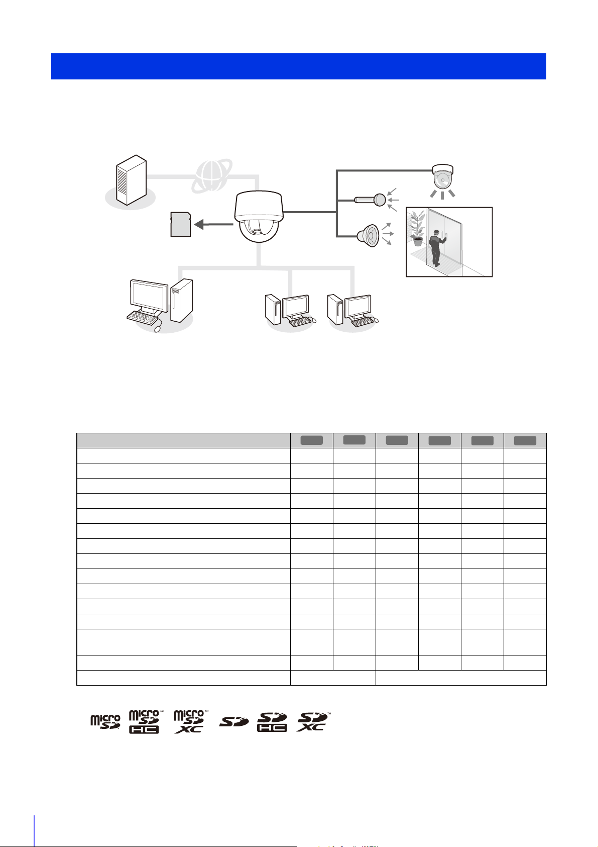
Network Camera Capabilities
Uploading
video
Recording to
memory card
Operation and setup by
administrator
[Admin Viewer]
Operation by guest users
[VB Viewer]
Monitoring by
intelligent functions
Inputting/outputting
audio
Using external devices
M641
M740
This network camera is capable of not just camera operations using the installed software but also recording and uploading
video and monitoring using various intelligent functions.
However, the functions that can be used differ depending on the model. For the difference in functions by model, refer to
the table below.
Table of Function Compatibility by Model
The functions for which availability differs depending on the model are shown below.
R11
Pan/Tilt ----
Digital PTZ - -
Audio I/O Terminals - - -
External Device Terminals - - -
Infrared Illumination - - - - -
Camera Angle Setting Tool - -
Audio Detection - - -
Auto Tracking ----
Event Triggered Preset Movement ----
Linked Event - - -
Panorama Creation Tool ----
View Restriction Setting Tool ----
microSD/microSDHC/microSDXC memory card
support*
SD/SDHC/SDXC memory card support* --
Max. Number of Registered Presets 257 21
* In this guide, “memory card” refers to the memory cards that can be used by the cameras.
-- --
R10
M640 M741
20
Page 21

1
Note
Camera Software
R11
R10
The software needed for camera setup and use is included on the camera and on the setup CD-ROM included with the
camera. The software can also be purchased separately.
Software Included on the Camera
The following software is included on the camera. It is automatically downloaded from the camera when you use it.
Admin Viewer/VB Viewer (P. 137)
These Viewers are used for camera control and for monitoring video and events.
Admin Viewer can only be used by administrators and registered users with camera control permissions, and allows
complete control of the camera.
The VB Viewer allows any user with camera access to use the camera, but the user is restricted to a limited set of
functions.
Admin Tools (P. 191)
This tool is used for making camera settings and for managing cameras.
• Privacy Mask Setting Tool
• Intelligent Function Setting Tool
• Log Viewer
• Recorded Video Utility
Before Use
• Panorama Creation Tool
• View Restriction Setting Tool
To use Admin Viewer and Admin Tools, .NET Framework 3.5 SP1 (when using Internet Explorer 8/9) or .NET Framework 4.5 (when
using Internet Explorer 10/11) is necessary.
If it is not installed on the computer, it will be automatically installed when using the installer (P. 28).
Software Included on the Setup CD-ROM
The software included on the setup CD-ROM is installed and used on a computer.
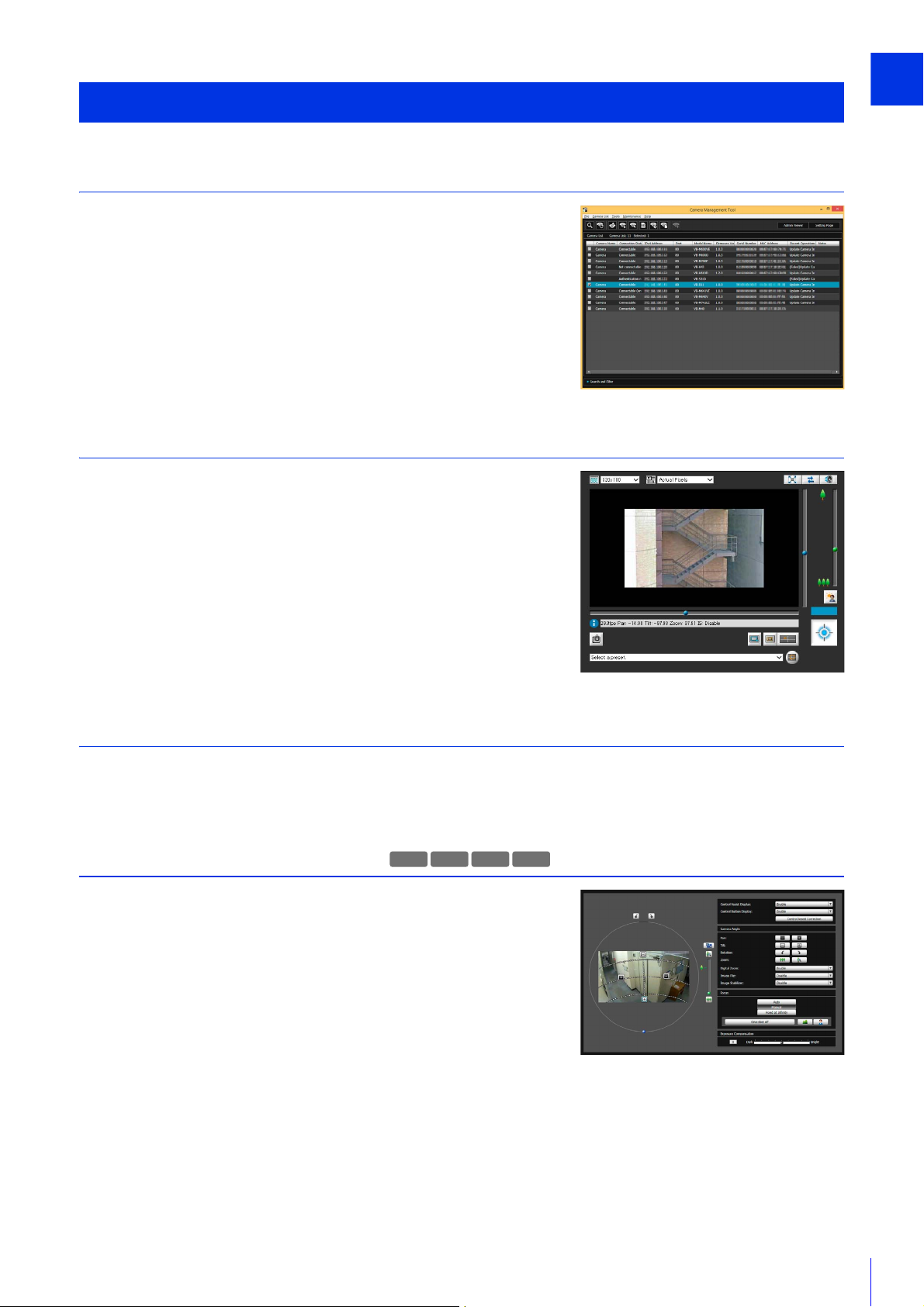
Camera Management Tool (P. 36)
This tool is used for batch managing multiple cameras, from making settings to performing maintenance. The
Camera Management Tool can perform the following tasks.
• Set various camera settings.
• Launch software included on the camera, such as Admin Viewer and Admin Tools.
• Update firmware, back up/restore settings, perform memory card and other operations, as well as, camera
maintenance.
This guide explains how to use this tool to make initial settings for cameras (P. 36). For details on other uses and
functions, please refer to the “Camera Management Tool User Manual”.
The Camera Management Tool can be installed by the installer application.
Installer location: Setup CD-ROM > [Applications] folder > VBToolsInstall.exe
21
Page 22
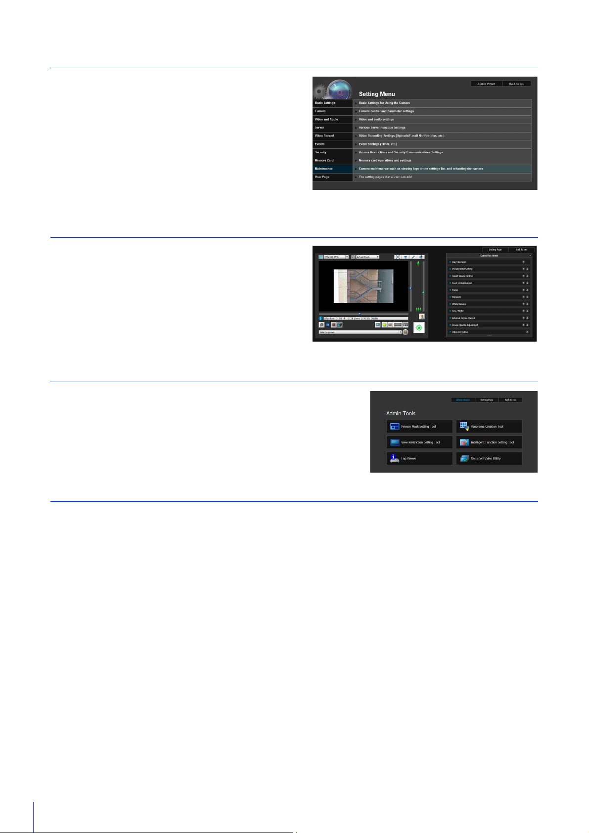
Camera Angle Setting Tool (P. 45)
M641
M640
M741
M740
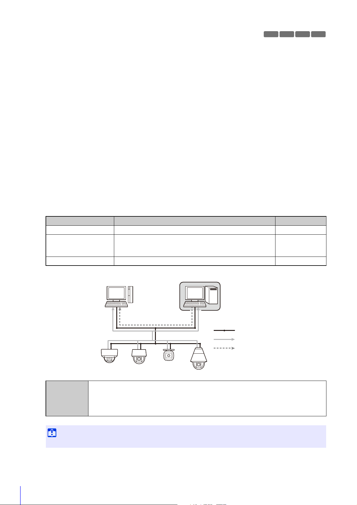
RM-Lite Viewer RM-Lite Storage Server
Network
Flow of video from the camera
Flow of recorded video
Important
This tool allows you to adjust the camera angle during installation by viewing video from the camera on the computer
screen via a network.
Installer location: Setup CD-ROM > [Applications] folder > VBToolsInstall.exe
Admin Tools Certificate
This is a digital certificate for using Admin Viewer and Admin Tools.
Installer location: Setup CD-ROM > [Applications] folder > VBToolsInstall.exe
Admin Viewer/Admin Tools with Proxy Authentication Support
Use these when going through a proxy server with proxy authentication.
Software location: Setup CD-ROM > ProxyAuthSupport folder
RM-Lite
This software displays, records and plays back video from up to four cameras via a network.
Software location: Setup CD-ROM > [Applications] folder > RMLiteInstall.exe
RM-Lite Software
Type Overview License
RM-Lite Storage Server Up to four cameras can be registered to record video (JPEG). 1 license
Plays video recorded in the storage server and displays live video
RM-Lite Viewer
RM-Lite Manager Use register cameras and configure recording schedules. 1 license
VB-R11VE, VB-R11, VB-R10VE, VB-M641VE, VB-M641V, VB-M640VE, VB-M640V, VB-M741LE,
Supported
cameras
VB-M740E, VB-H43, VB-H630VE, VB-H630D, VB-H730F, VB-M42, VB-M620VE, VB-M620D,
VB-M720F, VB-S30D, VB-S31D, VB-S800D, VB-S900F, VB-S805D, VB-S905F, VB-H41,
VB-H610VE, VB-H610D, VB-H710F, VB-M40, VB-M600VE, VB-M600D, VB-M700F, VB-C60,
VB-C500VD/VB-C500D, VB-C300, VB-C50i/VB-C50iR, VB-C50FSi/VB-C50Fi
(JPEG/H.264) from the camera.
Up to four cameras can be registered for the viewer.
1 license
To add the RM-Lite Viewer or RM-Lite Manager, you must purchase RM-Lite-V (sold separately).
22
Page 23

1
Note
For details on the usage, operating environment, and functions of RM-Lite, please refer to the “System Administrator Manual”.
Note
Additional Software/Licenses (Sold Separately)
You can purchase additional software and licenses as necessary.
Canon H.264 Additional User License AUL-VB
Additional license for viewing H.264 video with multiple computers via Admin Viewer or Recorded Video Utility.
Each camera includes one license. Additional licenses are necessary for multiple computers to view H.264 video
from a single camera.
RM-64/RM-25/RM-9
This software allows network cameras to be used for multipoint surveillance, and for displaying, recording and
playing back videos from the camera.
The number of cameras that can be registered with RM-64/RM-25/RM-9 varies: 64, 25, or 9 cameras respectively can
be registered. By using multiple Storage Servers, you can construct a surveillance system supporting up to 512
cameras.
Before Use
Licenses for upgrading from RM-9 to RM-25 or RM-64, and from RM-25 to RM-64 are also available.
RM-V
This additional license lets you install the RM-64/RM-25/RM-9 RM Manager and Viewer on multiple computers.
Purchase the license to be able to view video from the camera from multiple locations and for other similar purposes.
RM-Lite-V
This additional license lets you install the RM-Lite Viewer or RM-Lite Manager on multiple computers.
Purchase the license to be able to view video from the camera from multiple locations and for other similar purposes.
23
Page 24
Note
Operating Environment
For the latest information on this product (firmware and included software, user manual, operating environment, etc.),
please refer to the Canon Web Site.
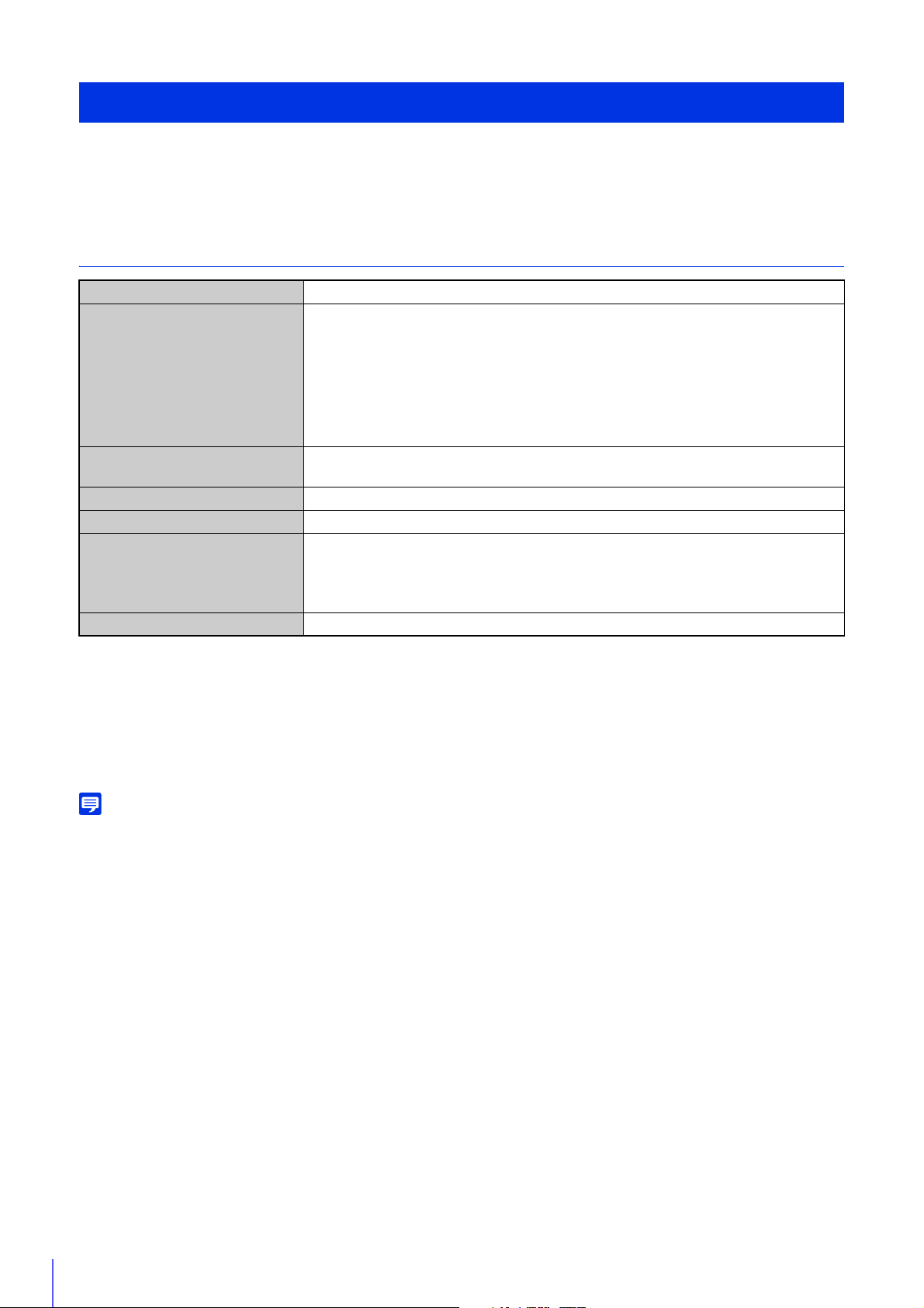
Camera Angle Setting Tool, Admin Viewer/VB Viewer, Admin Tools
CPU Intel Core i7-2600 or higher
Windows Vista Ultimate/Business/Enterprise/Home Premium SP2 32/64-bit
Windows 7 Ultimate/Professional/Enterprise/Home Premium SP1 32/64-bit
Windows 8/Windows 8 Pro/Windows 8 Enterprise 32/64-bit*
1
OS*
Web Browser
Memory 2 GB or more
Viewer Display 1920 x 1080 or higher
Software*
Audio A computer that supports audio is required to use the camera’s audio function.
*2
3
Windows 8.1/Windows 8.1 Pro/Windows 8.1 Enterprise 32/64-bit*
Windows Server 2008 Standard SP2 32/64-bit
Windows Server 2008 R2 Standard SP1 64-bit
Windows Server 2012 Standard 64-bit*
Windows Server 2012 R2 Standard 64-bit*
Internet Explorer 8/9 32-bit
Internet Explorer 10/11
.NET Framework 3.5 SP1 (when using Internet Explorer 8/9)
– Must be installed on Windows Vista and Windows Server 2008 systems
.NET Framework 4.5 (when using Internet Explorer 10/11)
– Must be installed on Windows 7 and Windows Server 2008 R2 systems
4
4
4
4
*1 Set the Control Panel’s font size (DPI) for Admin Tools and Admin Viewer to 100% or 125%.
*2 The browser must support JavaScript, XAML browser applications, and IFRAME (HTML tag).
The VB Viewer requires Cookies.
*3 Installation is unnecessary if only VB Viewer will be used. .NET Framework 3.5 SP1 and 4.5 are provided on the included
setup CD-ROM, and the appropriate installer is selected automatically depending on the version of Internet Explorer.
*4 The included software or the software installed on the camera cannot be started from the Start screen added to Windows
8 and later.
For details on using Camera Management Tool, please refer to “Camera Management Tool User Manual”.
24
Page 25
1
Steps for Setting Up Camera
Camera Management Tool
VB Viewer
M641
M640
M741
M740
Camera Angle Setting Tool
Step 1 Pre-Installation Preparations
Make preparations to use the camera via a network.
Install necessary software
“Install Software” (P. 28)
Check/configure computer and web browser security settings
“Check/Make Security Settings” (P. 31)
Use Camera Management Tool to configure initial camera settings.
“Making Initial Camera Settings” (P. 36)
Step 2 Check Camera Connection
Access the camera with a computer to ensure preparations have been properly
completed.
Access the camera top page using a web browser
“Access the Top Page from Camera Management Tool” (P. 41)
Before Use
Launch VB Viewer to check camera video
“Checking Camera Video” (P. 43)
Step 3 Install the Camera
Install the camera to suit the operating environment it will be used in.
“Installation Guide”
Step 4 Set the Camera Angle
Use Camera Angle Setting Tool to set the camera angle while checking video
on the computer screen.
“Camera Angle Setting Tool” (P. 45)
25
Page 26
Step 5 Adjust Advanced Settings According to Use
Setting Page
Admin Viewer
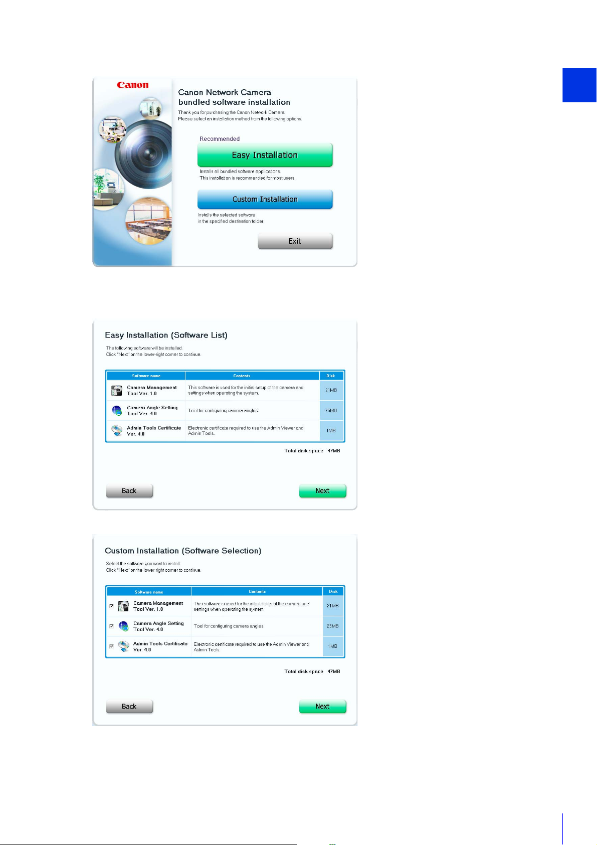
Advanced settings can be made in the Setting Menu, such as for
camera control and security, suitable for the intended camera
use.
“Setting Page” (P. 59)
Step 6 Use the Viewers
Use the viewers included on the camera.
The Admin Viewer is intended for administrators, and the VB
Viewer for guest users. Use the VB viewer to check content
distributed to guest users and Admin Viewer to make all settings
and fully check all preparations.
“Admin Viewer/VB Viewer” (P. 137)
Step 7 Use Admin Tools
Admin Tools can be used to set masks to ensure privacy, set view restrictions
and set the Intelligent Function to detect changes in video.
You can also view logs of the camera’s operational status, as well as browsing
and managing video recorded to the camera’s memory card.
“Admin Tools” (P. 191)
Troubleshooting
Please refer to the “Appendix” (P. 249), in case of error messages or problems.
26
Page 27

Chapter
Camera Setup
To prepare the camera for use, install necessary computer software and make initial settings for web browser
security and the camera.
When initial settings are complete, access the camera and check if video can be viewed.
Page 28

Note
Note
Note
Install Software
M741
M740
Use the setup CD-ROM included with the camera to install necessary software.
Necessary Software
You will need the following software:
• Camera Management Tool (P. 36)
• Admin Tools Certificate
• .NET Framework 3.5 SP1/.NET Framework 4.5 (unnecessary if already installed on computer)
M641 M640
• Camera Angle Setting Tool
• All computer users will be able to use Admin Viewer and Admin Tools if the Admin Tools Certificate is installed.
• If .NET Framework 3.5 SP1/.NET Framework 4.5 is not installed on the computer, the installer will automatically install the version
appropriate for the version of Internet Explorer used on the computer.
Software Installation
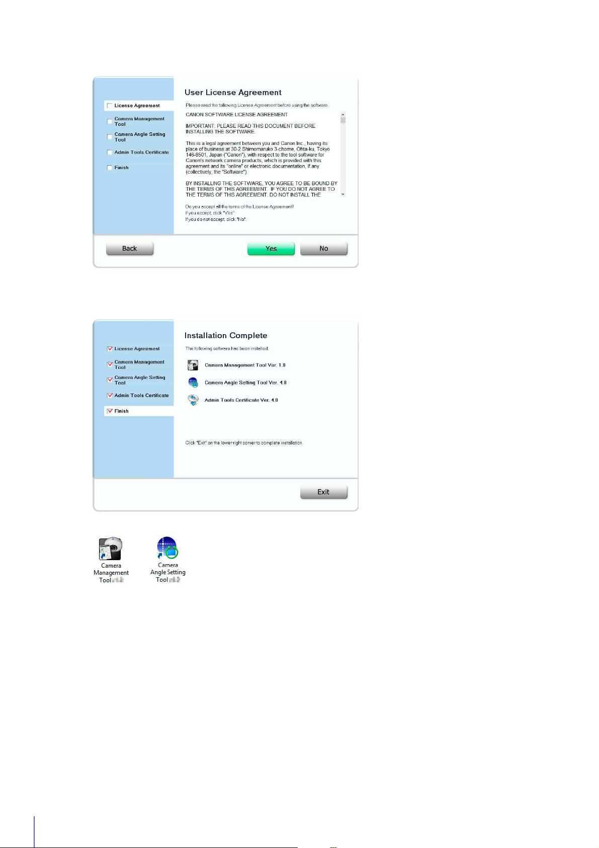
Installation Methods
The software can be installed together using [Easy Installation], or you can select which software to install using
[Custom Installation].
• [Easy Installation] will also install the Camera Angle Setting Tool, which cannot be used by VB-R11VE, VB-R11 and VB-R10VE.
Use [Custom Installation] and exclude the Camera Angle Setting Tool if you do not need to install it.
• If you plan to use Admin Viewer and Admin Tools on a computer that will not be used for the initial camera setup (a computer that
does not have Camera Management Tool installed), you can select [Custom installation] and only install the “Admin Tools
Certificate”.
Install Software
Insert the setup CD-ROM into the drive on the computer.
1
Confirm that all other applications have been closed.
2
Double-click the CD-ROM icon > [Applications] folder > [VBToolsInstall.exe] in Windows Explorer.
3
28
The installation screen appears.
If the [User Account Control] screen appears, click [Yes] or [Continue].
Page 29
2
Select the installation method.
4
Confirm or select the software that will be installed.
5
If you select [Easy Installation], confirm the software that will be installed and click [Next].
Camera Setup
If you select [Custom Installation], select the software to be installed and click [Next].
The User License Agreement screen appears.
29
Page 30
Read through the user license agreement and click [Yes] if you accept it.
6
Installation starts.
Click [Exit] or [Reboot].
7
The Camera Management Tool icon and Camera Angle Setting Tool icon (if installed) will appear on the desktop.
30
Page 31

2
Note
Check/Make Security Settings
Depending on Windows or Internet Explorer security settings, software or web browsers may be blocked from making
camera settings or using the camera.
Change or check security settings beforehand.
Check Firewall Settings
To use the Camera Management Tool on computers where Windows Firewall is enabled, you may need to register the
Camera Management Tool as an application allowed to communicate via the firewall.
Even if you do not perform the following steps, you can still register the Camera Management Tool with the [Windows Security Alert] dialog
box that appears when you launch the software (P. 36).
Click [System and Security] > [Windows Firewall] in [Control Panel].
1
Click [Allow an app or feature through Windows Firewall].
2
Camera Setup
31
Page 32

Note
Click [Change settings] > [Allow another app].
3
Select [Camera Management Tool] and click [Add].
4
32
Register the Camera IP Address as a Trusted Site
In Internet Explorer 9 or later and Windows Server 2008/Windows Server 2012, Internet Explorer’s security level for Internet
and intranet sites is set to [High] by default.
As a result, it may be necessary to register the camera’s IP address as a trusted site to access the Admin Viewer/VB Viewer,
Setting Page or Admin Tools.
• Set the camera IP address with the Camera Management Tool (P. 37).
• If you skip registration in this step, you can perform registration later using Camera Management Tool (P. 40).
Click [Tools] menu > [Internet Options] in Internet Explorer.
1
Click the [Security] tab.
2
Page 33

2
Note
Click [Trusted sites] > [Sites].
3
The [Trusted sites] dialog box appears.
Enter the IP address of the camera under [Add this Web site to the zone], then click [Add].
4
Camera Setup
• Clear the [Require server verification (https:) for all sites in this zone] check box if it is selected.
The camera’s IP address will be registered to the [Websites] list.
• You can register IP addresses for multiple cameras by using a wildcard (*) when entering the IP address.
For example, if you enter “192.160.1.*”, all cameras that share the “192.160.1” portion of the address will be registered as trusted
sites.
Settings When Using Windows Server
Register “about:internet” and the Camera Host Name
Admin Viewer and Admin Tools will not launch when IE ESC (Internet Explorer Enhanced Security Configuration) is
enabled in Windows Server 2008/Windows Server 2012.
Before using the tools, register “about:internet” and the host name for the connected camera in the Internet Explorer
“local intranet” or “trusted sites” list.
33
Page 34

Important
When “about:internet” is registered, the security level in Windows 7 is the same as when using Internet Explorer. After using Admin
Important
Viewer/Admin Tools, it is recommended that you remove “about:internet” and the camera name as necessary and restore the
original security level.
Security Settings When Using an SSL Connection
When an SSL connection to the camera is made from a web browser (Internet Explorer 9/10/11) in Windows Server
2008/Windows Server 2012, the following operations may cause the display of the blocked content dialog box and
prevent further operation.
• The launching of Admin Tools or Admin Viewer
• Audio reception from VB Viewer
This occurs when Internet Explorer Enhanced Security Configuration (IE ESC) is enabled in Internet Explorer 9/10/11.
Use the procedures below to change this setting.
Click [Tools] menu > [Internet Options] in Internet Explorer 9/10/11.
1
Click the [Advanced] tab.
2
Clear the [Do not save encrypted pages to disk] check box in [Security].
3
Note that when Internet Explorer Enhanced Security Configuration is turned back on, the [Do not save encrypted pages to disk]
check box also becomes enabled.
Sound Settings for Using the Audio Functions
34
In Windows Server 2008/Windows Server 2012, the sound function is disabled by default.
To use audio functions with the viewer, follow the steps below to enable the sound function.
Open [Control Panel] and click [Hardware].
1
Page 35

2
Click [Sound].
2
[Audio Service Not Running] dialog box appears.
Click [Yes].
3
Camera Setup
The [Sound] dialog box appears.
Click the [Playback] tab to confirm that an audio device has been installed.
4
If no audio device is installed, refer to your computer manual.
35
Page 36

Note
Making Initial Camera Settings
To use the camera, you must first set the network settings for the camera and then establish a network connection between
the camera and a computer. Use Camera Management Tool for these settings.
This section will explain, in addition to network settings, how to set the camera name, the date and time and other settings.
It will also explain how to use the Camera Management Tool to make initial camera settings.
• For details on using Camera Management Tool, please refer to “Camera Management Tool User Manual”.
• The settings made here will be reflected in the settings on the Setting Page (P. 59).
Launch the Camera Management Tool
Launch the Camera Management Tool that was installed onto the computer from the setup CD-ROM.
Connect the camera and computer to the network and turn on the power.
1
Please refer to “Installation Guide” > “Connecting the Camera”
Double-click the [Camera Management Tool] icon on the desktop.
2
Camera Management Tool launches and the [Camera Search Settings] dialog box appears.
Enter the factory default password (“camera”) into [Administrator Password] and click [OK].
3
The Camera Management Tool main screen will appear.
Searching for Cameras and Setting up Networks
This will explain network settings so you can search for network connected cameras and connect to them from a computer.
The examples will be for setting one camera. The Camera Management Tool, however, can set multiple cameras at the
same time.
36
Page 37

2
Click the [Search Camera] icon.
(1)
(2)
(3)
(4)
(5)
(6)
(7)
1
Detected cameras will appear in the camera list.
2
Select a camera in the camera list and click the [Basic Camera Settings] icon.
3
Camera Setup
The [Basic Camera Settings] dialog box appears.
Set each of the [Network] items.
4
(1) [IPv4 Address Setting Method]
Select the method for setting the IPv4 address.
If [Manual] is selected, directly enter values that suit the environment in which the camera is used.
If [Auto (DHCP)] is selected, the value automatically acquired from the DHCP server will be entered in [IPv4
Address], [Subnet Mask] and [IPv4 Default Gateway Address].
(2) [IPv4 Address]
If you selected [IPv4 Address Setting Method] > [Manual], enter a fixed IPv4 address.
(3) [Subnet Mask]
If you selected [IPv4 Address Setting Method] > [Manual], enter the designated subnet mask values for each
network.
(4) [Enter a default gateway address]
Select this to manually set the default gateway address.
37
Page 38

(5) [IPv4 Default Gateway Address]
Important
Be sure to set this if you select [IPv4 Address Setting Method] > [Manual] and connect to the camera with a
different subnet than that of the viewer.
(6) [AutoIP]
Select this to enable or disable AutoIP.
(7) [IPv4 Address (AutoIP)]
When [Enable] is selected for [AutoIP], an automatically set IPv4 address is displayed.
Click [OK].
5
The camera will restart and the settings will take effect.
When you click [OK], other settings in ([Password], [Date and Time], [Camera], [Video]) [Basic Camera Settings]
will also take effect.
Set the Password, Date and Time, Camera Name and Video
Set basic camera information, such as the camera name, administrator password and date.
Once you have entered information for each item, click [OK].
Password Setting
Click [Password] and set the administrator password.
To ensure system security, be sure to change the administrator password. Do not forget the new password.
38
Page 39

2
Date and Time Settings
Click [Date and Time] and make settings such as the camera date and time setting method, time zone, and daylight
saving time.
For details on each item, please refer to “Setting” (P. 69) in “Set the Date/Time”.
Camera Name Setting
Camera Setup
Click [Camera] and set the camera name displayed in the viewers and other software.
For setting details, please refer to “Camera Name” (P. 75) in “Set General Camera Controls”.
39
Page 40

Video Settings
Note
Click [Video] and configure the size and quality settings of the video transmitted from the camera.
For setting details, please refer to “Set Video Size and Quality [Basic Settings] > [Video Settings]” (P. 72).
Registering Camera’s IP Address to Trusted Sites
With Internet Explorer 9 or later and Windows Server 2008/Windows Server 2012, Internet Explorer’s security level for
Internet and intranet sites is set to [High] by default.
As a result, it may be necessary to register the camera’s IP address as a trusted site to access the Admin Viewer/VB Viewer,
Setting Page or Admin Tools.
Select a camera from the camera list.
1
Click [Maintenance] menu > [Add to Trusted Sites].
2
A confirmation message appears.
Click [OK].
3
The camera will be registered as a trusted site for Internet Explorer.
The registered information will be loaded when Internet Explorer is restarted. Close and restart Internet Explorer if it is running.
40
Page 41

2
Note
Access the Top Page of the Camera to Check Video
(1)
(2)
(3)
(4)
(5)
When camera installation and initial settings are complete, access the camera with the Camera Management Tool and
check if video can be viewed properly.
Access the Top Page from Camera Management Tool
You can use the Camera Management Tool to launch the camera top page.
Launch the Camera Management Tool (P. 36)
1
Double-click the IPv4 address of a camera in the camera list to launch its top page.
2
The web browser will start and the camera top page appears.
Camera Setup
• The web browser will not start when [Connection Status] for a camera is [Not connectable].
• You can also launch the camera top page by entering the IP address configured with the Camera Management Tool (P. 37)
directly into the web browser.
• If the camera top page does not launch, please refer to “Troubleshooting” (P. 254).
Top Page
From the top page of the camera, you can navigate to the Setting Page to configure various camera settings, launch Admin
Tools, and access Viewers to view video.
(1) Language Button
41
Page 42

Click to switch the display language.
Note
Important
Authentication Screen for Setting Page Authentication Screen for Admin Tools/Admin Viewer
(2) [Setting Page]
Displays the Setting Page (P. 60).
You can make initial camera settings and settings to suit how the camera will be used.
(3) [Admin Tools]
Displays the Admin Tools top page (P. 193).
You can launch various tools for making settings, such as for using the camera, or launch a utility for managing
recorded video.
(4) [Admin Viewer]
Launches the Admin Viewer (P. 43).
(5) [VB Viewer]
Launches the VB Viewer (P. 43).
User Authentication
When you use the Setting Page, Admin Tools or Admin Viewer, an authentication screen appears, and you are
prompted to enter a user name and password.
If you enter the wrong user name or password, you will not be able to connect to the camera. Enter the correct user
name and password and connect to the camera.
The factory default user name and password are:
User Name: root
Password: camera
The user name “root” is the administrator account for the camera.
• To ensure system security, be sure to change the administrator password. Do not forget the new password.
• Restore factory default settings if you have forgotten the administrator password (P. 270). Note that this will reset all camera
settings to factory default settings except for date and time.
• If you connect to the camera using the administrator account, it will not be possible to connect with administrator privileges from
a different computer.
• If the administrator and an authorized user share the VB Viewer on the same computer, it is strongly recommended that the
[Remember my credentials] check box be cleared.
• The Admin Tools and the Admin Viewer cannot be used if an IPv6 address is specified. Only host names are supported for IPv6
connections.
• Only administrators can connect to a camera using the Setting Page and Admin Tools.
• Authorized users with camera control privileges can also connect using Admin Viewer. You can set the user privileges of
registered users with [Security] > [User Restrictions] > [User Authority] on the Setting Page (P. 118).
42
Page 43

2
• Depending on the security settings in Internet Explorer, the blocked content dialog box may appear when attempting to access
Note
the Setting Page, Admin Tools or the Viewers when using the camera with Internet Explorer 9 or later, or on Windows Server 2008/
Windows Server 2012. If this happens, click [Add] to register the camera IP address as a trusted site.
Checking Camera Video
Check the camera video with a viewer. VB Viewer and Admin Viewer are available.
This section only explains how to launch a viewer for checking video. For details on how to use each Viewer, please refer to
“Admin Viewer/VB Viewer” (P. 137).
If the blocked content dialog box appears when you launch a viewer, click [Add] in the dialog box to register the camera’s IP address as a
trusted site.
Camera Setup
Viewing Video With VB Viewer
VB Viewer allows any user with camera access to use the camera. The user, however, is restricted to a limited set of
functions.
When you click [VB Viewer] on the top page, the VB Viewer launches and displays the camera video.
Viewing Video With Admin Viewer
The Admin Viewer can only be used by administrators and registered users with camera control privilege. It allows
complete control of the camera.
Click [Admin Viewer] on the top page.
1
The user authentication window appears.
43
Page 44

Enter a user name and password (P. 42) and click [OK].
2
The Admin Viewer launches and displays the camera video.
44
Page 45

Chapter
M641
M741
Camera Angle Setting Tool
After installing the camera, connect to it with the Camera Angle Setting Tool and view the displayed video to
make settings, such as the camera angle, focus and exposure.
M640
M740
Page 46

Note
Launch the Camera Angle Setting Tool and Connect to a
Important
Important
M741
M740
Camera
The Camera Angle Setting Tool allows you to view displayed video on a computer to make settings, such as the camera
angle and focus.
Use this to adjust the camera during installation or if the camera has been moved from its original position.
The following gives an overview of the settings that can be made with the Camera Angle Setting Tool.
M641 M640
Pan, Tilt, Rotation, Zoom, Focus, Image Flip
Zoom, Focus, Image Flip
• The Camera Angle Setting Tool is for use when installing the camera. Do not use on a daily basis. Frequent use may result in camera
malfunction.
• After changing settings with the Camera Angle Setting Tool, make sure that the settings made with the Setting Page and Admin Tools
function correctly.
• The Camera Angle Setting Tool cannot be used via a proxy server.
• The upload function cannot be used while the Camera Angle Setting Tool is connected.
Launch the Camera Angle Setting Tool
Double-click the [Camera Angle Setting Tool] icon on the desktop to launch it.
You can also launch the Camera Angle Setting Tool from the Camera Management Tool. For details, please refer to the “Camera
Management Tool User Manual”.
Connect to the Camera
Use the Camera Angle Setting Tool to select the camera on which you want to set the camera angle.
• Connections to a single camera are limited to 30 minutes. If the connection is closed because you exceeded the time limit before you
completed camera angle settings, reconnect to the camera.
• Multiple computers cannot simultaneously connect to the same camera using the Camera Angle Setting Tool.
There are two methods for connecting to the camera.
• Specify camera information.
• Use a Camera Specification File (P. 56)
46
Page 47

3
Connect by Specifying Camera Information
Note
(1)
(2)
(3)
(4)
(5)
Click [File] menu > [Connect].
1
The [Connection settings] dialog box appears.
Enter the connection settings for the camera.
2
Camera Angle Setting Tool
(1) [Host Name]
Enter the host name or IP address of the camera (P. 37).
(2) [Administrator User Name]
Enter the administrator user name for the camera (P. 42).
(3) [Administrator Password]
Enter the administrator password for the camera (P. 42).
(4) [Enable SSL Communications]
Select this to connect to the camera using SSL communication.
Normally, disabling SSL communication (the factory default setting) is not an issue (P. 123).
(5) [Port]
Set the HTTP port number to 80, 443 or a value in the range of 1024 to 65535.
Normally use [80] (factory default setting) (P. 89).
Click [OK].
3
A confirmation message will appear.
Connecting to the camera with the Camera Angle Setting Tool will disconnect connections to that camera from Viewers and
recording software, except for those connecting via RTP.
Click [Yes].
4
You will connect to the camera and live video from it will appear.
47
Page 48

Use a Camera Specification File for Connecting
You can connect to a camera by loading camera information listed in a camera specification file (P. 56).
Click [File] menu > [Select Camera].
1
The [Select Camera] dialog box appears.
Click [Load camera specification file].
2
Select a camera specification file and click [Open].
3
The camera specification file will be loaded and the camera name will appear in [Camera List].
48
Page 49

3
Note
Select a camera to connect to and click [Connect].
Next camera
4
You will connect to the camera.
Connect to the Next Camera
Camera Angle Setting Tool
After setting the camera angle, click [Next] to connect to the next camera.
You will be disconnected from the current camera and connected to the next camera appearing in the list.
• The [Select Camera] dialog box will continue to display until you close the Camera Angle Setting Tool or click the X in the upper
right corner of the dialog box.
• The camera list will be discarded when the Camera Angle Setting Tool is closed. Load the camera specification file the next time
you launch the Camera Angle Setting Tool.
Disconnect from the Camera and Close the Software
Once you have completed setting the camera angle, follow the steps below to disconnect from the camera and close the
Camera Angle Setting Tool. Note that camera angle settings will be lost if you turn the camera on/off without performing
these steps.
49
Page 50

Click [File] menu > [Disconnect].
1
You will disconnect from the camera.
Click [File] menu > [Exit].
2
The Camera Angle Setting Tool will close.
50
Page 51

3
Camera Angle Setting Tool Screen
(11)
(12)
(13)
(4)
(14)
(15)
(16)
(17)
(18)
(5)
(6)
(8)
(2)
(6)
(1)
(3)
(4)
(5)(7) (10) (9) (8)
(1)
(14)
(15)
(16)
(17)
(18)
(8)
(2)
(10) (9) (8)
M641 M640
Camera Angle Setting Tool
M741 M740
(1) Video Display Area
Camera video appears here.
(2) [Switch Screen Size] Button
Switch the Camera Angle Setting Tool screen between small and large sizes.
You can select the screen size with [Display] menu > [Display screen size].
(3) Control Assist Display
Display dotted lines indicating the possible ranges for panning and tilting.
M641 M640
51
Page 52

(4) [Pan] Buttons
Important
M641
M641
M641
M640
Pan the camera.
M641 M640
(5) [Tilt] Buttons
M641 M640
Tilt the camera.
(6) [Rotation] Buttons
M640
Rotate the camera.
(7) [Rotation] Slider
M640
Click on the slider or drag the slider to rotate the camera angle.
(8) [Zoom] Buttons
Zoom the camera.
(9) [Zoom] Slider
Click on the slider or drag the slider to zoom the camera.
(10) Optical telephoto end icon
Appears when [Digital Zoom] > [Enable] has been selected. Digital zoom is used when dragging the slider
above this icon.
(11) [Control Assist Display] Selection Menu
Select whether or not to display control assistance in the video display area.
(12) [Control Button Display] Selection Menu
M641 M640
Select whether or not to display pan and tilt control buttons in the video display area.
(13) [Control Assist Correction] Button
M641 M640
If you click this when the displayed control assistance does not match the actual camera angle, the actual
camera angle will be confirmed and the position of the displayed control assistance automatically corrected.
Correction takes approximately one minute.
(14) [Digital Zoom]
Select whether or not to use digital zoom.
If you select [Enable], the digital zoom range will appear on the zoom slider and you will be able to use digital
zoom.
The higher the digital zoom ratio, the lower the video quality.
(15) [Image Flip] Selection Menu
Select the orientation of the camera video.
If [Enable] is selected, the video is displayed rotated 180 degrees.
(16) [Image Stabilizer]
Select this to reduce blur in video due to camera vibration.
If there is still blur after selecting [On1], select [On2].
The angle of view will be narrower and the video noisier when using stabilization compared to when it is not
used.
• Stabilization will not affect blurring of subjects.
• Stabilization is not effective beyond a certain degree of vibration or for momentary vibrations.
• If you select [On2], it is recommended selecting a video reception size less than 640 × 480.
• If you use stabilization, please refer to the information listed in the following “Important” sections.
– The “Important” section in “View Restriction Setting Tool” (P. 207).
– The “Important” section in “View Video With Admin Viewer” (P. 143).
– The “Important” section in “Register Presets” (P. 170).
(17) [Focus]
Focus the camera (P. 54).
(18) [Exposure Compensation] Slider
Adjust exposure to suit the brightness of subjects (P. 55).
52
Page 53

3
Note
Set the Camera Angle
Important
M641
M640
M641
After connecting to the camera, view the displayed video to make settings, such as the camera angle and zoom.
You will have to reconfigure Intelligent Function detection area settings, privacy mask settings, or preset settings you have already made
on a camera, if you change settings on that camera with the Camera Angle Setting Tool.
Set the Camera Angle and Zoom
You can set the camera angle and zoom using the video display area or buttons.
Make Settings with the Operation Buttons and Sliders
You can set the camera angle with the [Pan], [Tilt] and [Rotation] buttons.
While you push a button, the camera angle will change in that direction. When you release the button, the camera
angle will stop.
If you rotate the camera angle using the [Rotation] slider, release the mouse button when the video display area is
horizontal.
Pans left or right.
Tilts up or down.
Rotates.
Camera Angle Setting Tool
Set Camera Angle by Clicking Video
M640
If you click anywhere in the video display area, the camera angle will change to center on that location.
If you click outside the pan or tilt range, however, the camera angle will only change for the one which is within its
range.
If the camera moves differently than the intended operation, or if settings in the full range displayed by control assist cannot be
made, control assist may be out of alignment with the actual camera angle. If this happens, reset the camera angle after clicking
[Control Assist Correction].
53
Page 54

Change the Camera Zoom Ratio
Note
Digital Zoom Range
Optical telephoto end icon
(1)
(2)
(3)
(4)
(5)
You can change the zoom ratio of the camera with the [Zoom] buttons or [Zoom] slider.
Operation will continue while you hold a [Zoom] button down and stop when you release it.
Zooms in.
Zooms out.
If you drag the slider handle, the camera zoom ratio will change according to the position on the slider.
If you select [Digital Zoom] > [Enable], the maximum optical telephoto icon and digital zoom range will appear and
you will be able to use digital zoom.
The higher the digital zoom ratio, however, the lower the video quality becomes.
Set the Focus and Exposure Compensation
This focuses on the subject. Adjust exposure to suit the brightness of subjects.
The exposure compensation value set with the Camera Angle Setting Tool will be reset when the camera is rebooted.
Set the Focus
You can automatically or manually focus on subjects, or set focus to infinity. You can use One-shot AF to focus on
subjects manually.
(1) [Auto]
Automatically focuses on the subject.
(2) [Manual]
Use buttons ((4) and (5)) to manually adjust focus.
(3) [Fixed at Infinity]
(4) [One-shot AF]
(5) Far and Near Buttons
54
Fixes the focus near infinity.
Use when the focus mode is set to [Manual]. When you click this, it will focus once using autofocus and then
switch to manual focus.
Use to adjust focus when the focus mode is set to [Manual].
Focus will change while you hold the buttons down and stop when you release them.
Page 55

3
Note
Focuses further away.
A white wall or other subject
lacking bright/dark contrast
A slanting
subject
A subject reflecting
strong light
A subject consisting of only
slant lines or horizontal stripes
A subject having no form,
such as flame or smoke
A subject seen
through glass
A fast moving
subject
A dark area or
night view
Subjects both
near and far
Focuses nearer.
• Focusing may be difficult for the following types of subjects when using [Auto] or [One-shot AF].
Difficult to Focus Subjects
• It is recommended that you check that the camera is focused whenever you restart the camera or use One-shot
AF.
• The focus ranges (approximate) are shown in the table below.
Focus Mode
Auto/Manual 0.3 m (12 in.) – infinity 0.3 m (12 in.) – infinity
Fixed at Infinity Fixed near infinity*
Day mode Night mode
Day/Night Settings
Camera Angle Setting Tool
Set the Exposure Compensation
* Using infrared illumination from an external device may throw the camera out of focus.
Set the video brightness.
55
Page 56

Use a Camera Specification File
Important
Important
If you create a camera specification file listing the information needed to connect to cameras beforehand, you can load the
file with the Camera Angle Setting Tool and connect to cameras that appear in the camera list simply by specifying them.
When you set the camera angle of multiple cameras, this eliminates the need to enter information, such as the host name
and password, of each camera individually.
Enter the actual administrator passwords in the camera specification file. Handle the camera specification file with sufficient care.
Create a Camera Specification File
Create the camera specification file with an editor like the text editor and save the file as .csv format.
The maximum number of cameras that can be listed in a camera specification file is 30. An error will be generated if you try to load a file
with the Camera Angle Setting Tool listing 31 or more cameras.
Information Listed in a Camera Specification File
The camera specification file consists of the following format.
Header
Row
Individual
Camera
Information
(Max. 30
Cameras)
The first row serves as a header row listing the titles of each column.
Each row from the second row on, lists the information for one camera per row.
The information listed in each column is described below.
Header Row Title Information Listed in Column
RegisterName Enter any camera name. This will appear in the camera list when connected.
HostName Host name or IP address of the camera.
PortNumber HTTP port number for the camera (default setting is 80).
UserName Administrator user name for the camera (default setting is “root”).
Password Administrator password for the camera (default setting is “camera”).
ConnectType
RegisterName HostName PortNumber UserName Password ConnectType
B1F VB-M641VE 192.168.100.1 80 root camera1 0
1Fa VB-M640VE 192.168.100.2 80 root camera2 0
1Fb VB-M641V 192.168.100.3 80 root camera3 0
•
•
•
•
•
•
•
•
•
•
•
•
•
•
•
•
•
•
•
•
•
•
•
•
•
Enable SSL communications: 1
Disable SSL communications: 0 (default setting is 0).
•
•
•
•
•
56
Page 57

3
Example Using a Text Editor for Entry
Important
Enter each item separated by a comma. Give the file the .csv extension and save it.
RegisterName,HostName,PortNumber,UserName,Password,ConnectType
B1F VB-M641VE,192.168.100.1,80,root,camera1,0
1Fa VB-M640VE,192.168.100.2,80,root,camera2,0
1Fb VB-M641V,192.168.100.3,80,root,camera3,0
2Fa VB-M641V,192.168.100.4,80,root,camera4,0
2Fb VB-M641V,192.168.100.5,80,root,camera5,0
3Fa VB-M741LE,192.168.100.6,80,root,camera6,0
R VB-M740E,192.168.100.7,443,root,camera7,0
If you separate items with a delimiter other than a comma, such as a semicolon, the Camera Angle Setting Tool will not be able to
load the file.
Camera Angle Setting Tool
57
Page 58

58
Page 59

Chapter
Setting Page
The Setting Page is used to make necessary basic settings after camera installation, such as, network, video
and security settings, and to make settings to suit the situation in which a camera will be used.
It also has the maintenance menu for the camera.
Page 60

Note
How to Use The Setting Page
Important
(3)
(1) (2)
This section explains operation up to displaying the Setting Page, and common Setting Page operations.
Access the Setting Page
Use a web browser to access the camera’s top page to display the Setting Page.
Launch the camera top page and click [Setting Page] (P. 41).
1
A user authentication window appears.
Enter a user name and password (P. 42) and click [OK].
2
The Setting Menu will appear.
You can also access the Setting Page from the Camera Management Tool. For details, please refer to the “Camera Management
Tool User Manual”.
Setting Menu
60
(1) [Admin Viewer]
Click this button to launch Admin Viewer.
(2) [Back to top]
Click this button to navigate to the top page.
(3) Setting Menus
If you click this, a submenu (P. 62) will appear (excluding the [Memory Card], [Maintenance] and [User Page]
menus). Click the submenu to navigate to each Setting Page.
• To ensure security, exit the web browser after completing settings on the Setting Page and after using Admin Viewer/Admin
Tools.
• Do not open multiple Setting Pages at one time and try to change the settings of a single camera.
Page 61

4
Common Setting Page Operations
Important
Important
This section explains basic Setting Page operations, and operations common to all Setting Pages.
Applying Changes to Settings
When a setting is changed on the Setting Page, [Apply] shown on the top right and bottom right of the Setting Page
changes from grayed-out to blue.
Click [Apply] in this state to apply the changed settings.
Click [Clear] to revert to the previous settings.
Setting Changes Requiring Rebooting
Items that require the camera to be rebooted in order to apply the changed settings are indicated with an orange
symbol to their right.
When any item indicated with an orange symbol is changed, [Apply] shown at the top right and bottom right of each
Setting Page changes to [Apply and reboot].
Setting Page
Click [Apply and reboot] to apply the changed settings and reboot the camera.
Click [Clear] to revert to the previous settings.
Setting changes will be lost if you navigate to another Setting Page without clicking [Apply] or [Apply and reboot]. Be sure to click
[Apply] or [Apply and reboot] to apply the changed settings.
Return to the Setting Menu
Click [Settings menu] at the top right of each Setting Page to return to the top menu.
Do not use the [Back] or [Forward] button in the web browser to navigate Setting Pages. The changed settings may revert to the
original settings or unwanted setting changes may be applied.
Help
Click [Help] at the beginning of any setting item to display a detailed explanation of that setting item.
Setting Ranges and Character Limits
For settings where you enter numerical values or characters, the setting range or character limits that can be entered
will be displayed.
Please enter the settings within the displayed limits.
61
Page 62

About Each Setting Page
• Network (P. 64)
Network settings for connecting to the camera.
• Password (P. 68)
Use this to change the administrator password from the
default password.
• Date and Time (P. 69)
Camera date and time settings.
• Video Settings (P. 72)
General video settings, such as the size and quality of
video transmitted from the camera.
Basic Settings
Camera
Video and Audio
R11
M741
Video
M740
Server
• Camera Settings (P. 75)
Settings for the camera name and external input/output
devices, and for camera use and installation settings.
•Initial Setting (P. 79)
Sets initial settings, such as video quality compensation, at
camera start up.
• Video Settings (P. 72)
•ADSR (P. 82)
ADSR is an abbreviation for Area-specific Data Size
Reduction.
Reduces the size of transmitted H.264 video by reducing
the video quality of unspecified area.
• On-screen Display (P. 85)
Displays the date and time, camera name and other UI
strings on the Viewer.
• Audio Settings (P. 87)
Settings for audio input from the microphone connected to
the camera and audio output from the Viewer.
R11
M641
M741
• Server Settings (P. 89)
Settings for HTTP server, SNMP server, FTP server usage
or WS-Security time checks.
• Video Server (P. 91)
Settings for clients that can be connected to a video
server.
• Audio Server (P. 92)
Settings for audio transmission from the camera to the
computer, and audio reception from the computer to the
camera.
•RTP Server (P. 93)
Settings for RTP streaming.
R11
M641
This section will give an overview of each item in Setting Menu and each list of submenus.
Each of the [Basic Settings], [Video and Audio]/[Video], and [Video Record] menus has a [Video Settings] submenu, but
the functions are all common. The functions can be set in any of the menus and the settings will be reflected in all of the
[Video Settings] submenus.
M641
R10
M640
62
M741
Page 63

4
• Video Settings (P. 72)
• Upload (P. 96)
Settings for uploading video via HTTP or FTP when an
event is triggered.
• Memory Card (P. 101)
Settings for recording video to a memory card when an
event is triggered.
The settings of this item are the same as those of the
[Memory Card] menu. The settings can be made with
either of them.
• E-mail Notification (P. 102)
Settings for sending an e-mail notification to a specified
recipient when an event is triggered.
Video Record
Event
Security
Memory Card (P. 130)
Maintenance (P. 134)
• External Device (P. 104)
Operation settings for external device output and for
external device input triggered events.
• Audio Settings (P. 87)
The settings of this item are the same as those of [Video
and Audio] > [Audio Settings].
• Audio Detection (P. 107)
Detected changes in audio input from the microphone
connected to the camera can trigger operations such as
video recording or e-mail notification.
•Timer (P.110)
The timer function can generate events that can trigger
operations, such as video recording and e-mail
notifications, at regular intervals.
• Switch Day/Night (P. 112)
The camera angle can be moved to preset positions when
events cause Day Mode and Night Mode to switch.
• Linked Event (P. 113)
By linking two types of events, a single event is triggered.
M641
M741
R11
M641
M741
R11
M641
M741
• User Restrictions (P. 118)
Used for adding new authorized users that can access the
Admin Viewer, and for setting permissions for users.
• Host Restrictions (P. 119)
Separate access control from IPv4 and IPv6 addresses
can be set.
• SSL/TLS (P. 121)
Certificate creation, administrative settings and encrypted
communication settings.
• 802.1X (P. 124)
Settings for 802.1X authentication and authentication
status display, and for certificate administration.
•IPsec (P.126)
Settings for using IPsec.
Perform memory card operations or configure settings.
Check logs or settings, or perform camera maintenance.
User Page
Link to web page customized by the user.
For information on the User Page, contact a Canon Customer Service Center.
R11
Setting Page
R11
M641
M741
63
Page 64

Configure Network Settings
Important
Important
[Basic Settings] > [Network]
Network settings for connecting to the camera.
If any network settings are changed, the camera may become inaccessible from the active web browser. If this occurs, a confirmation
dialog box will appear when you click [Apply] or [Apply and reboot]. Click [OK] to apply the new settings.
If you reboot the camera after changing settings and cannot connect to the camera from the web browser, any available URI for
connecting to the camera will be displayed in a message. If you cannot connect to the camera through the displayed URI, contact your
system administrator.
LAN
Set the LAN communication method and size of video transmitted from the camera.
[LAN Interface]
Select the interface suited to the device for connecting to the camera. Generally use [Auto].
[Maximum Packet Size]
Enter the maximum packet size to be transmitted by the camera. Normally there is no need to change the default setting of
1500.
A setting of 1280 or greater is necessary when using IPv6.
When using ADSL, setting a slightly lower value may increase transmission efficiency.
IPv4
Settings for using IPv4 to connect to the camera. The IPv4 address can be assigned by the DHCP server automatically or
set manually.
• Contact your System Administrator for the [IPv4 Address], [Subnet Mask] and [IPv4 Default Gateway Address] if you set the IPv4
address manually.
• If any of the [IPv4 Address], [Subnet Mask] or [IPv4 Default Gateway Address] settings are wrong, the camera may become
inaccessible via the network. If this occurs, use the Camera Management Tool to reset the address (P. 36).
[IPv4 Address Setting Method]
Select the method for setting the IPv4 address.
64
Page 65

4
For [Manual], enter a fixed IPv4 address into [IPv4 Address].
Important
Important
For [Auto (DHCP)], the settings acquired from the DHCP server will be automatically entered in [IPv4 Address], [Subnet
Mask] and [IPv4 Default Gateway Address].
If [Auto (DHCP)] is selected as the IPv4 address setting method, the IPv4 address may not be assigned correctly in certain environments,
such as when a router is present between the DHCP server and the camera. If this occurs, select [Manual] and enter a fixed IPv4
address.
[IPv4 Address]
When [IPv4 Address Setting Method] is set to [Manual], enter a fixed IPv4 address.
The IP address cannot start with 127., such as 127.0.0.1.
[Subnet Mask]
When [IPv4 Address Setting Method] is set to [Manual], enter the designated subnet mask values for each network.
[IPv4 Default Gateway Address]
When [IPv4 Address Setting Method] is set to [Manual], enter a default gateway IP address. Be sure to set this when
connecting the camera to a different subnet from that of the Viewer.
[AutoIP]
Select this to enable or disable AutoIP.
[IPv4 Address (AutoIP)]
When [AutoIP] is set to [Enable], an automatically set IPv4 address is displayed.
IPv6
Settings for using IPv6 to connect to the camera. The IPv6 address can be assigned by the RA or DHCPv6 server
automatically or set manually.
Contact your System Administrator for the [IPv6 Address], [Prefix Length] and [IPv6 Default Gateway Address] if you set the IPv6 address
manually.
Setting Page
[IPv6]
Select this to enable or disable IPv6.
[Auto (RA)]
Select [Enable] to set an address automatically using RA (Router Advertisement, network information automatically
transmitted from a router).
[Auto (DHCPv6)]
Select [Enable] to use DHCPv6 to set an address automatically.
65
Page 66

[IPv6 Address (Manual)]
Note
Note
Enter a fixed IPv6 address if you set the address manually.
[Prefix Length]
Enter a prefix length if [Disable] is specified in [Auto (RA)].
[IPv6 Default Gateway Address]
Enter a default gateway address if [Disable] is specified in [Auto (RA)]. Be sure to set this when connecting the camera to a
different subnet from that of the Viewer.
[IPv6 Address (Auto)]
If [Enable] is specified in [IPv6] and [Enable] is specified in [Auto (RA)] and [Auto (DHCPv6)], then the automatically
acquired address will be shown.
In an environment where IPv6 cannot be used, and IPv6/Auto is set to [Enable], then only the link-local address will be displayed in the
[IPv6 Address (Auto)] field.
DNS
Set the DNS server address. The DNS server address can be set manually or automatically assigned by a DHCP/DHCPv6
server.
66
[Name Server Address 1], [Name Server Address 2]
Enter the name server address you want to register. To register only one address, keep the [Name Server Address 2] field
blank.
You must set at least one if you manually set the IPv4 address or IPv6 address.
If [Name Server Address 1] is unavailable, [Name Server Address 2] will be accessed. However, [Name Server Address 2] must be set in
advance.
[Auto-Setting of Name Server Address]
Select the server to use for automatically setting the name server address.
To set [Use DHCP], select [Auto (DHCP)] in [IPv4 Address Setting Method] (P. 64).
To set [Use DHCPv6], select [Enable] in [IPv6], then select [Enable] in [Auto (DHCPv6)] (P. 65).
[Name Server Address (DHCP)]
Select [Use DHCP] or [Use DHCP/DHCPv6] in [Auto-Setting of Name Server Address] to display the name server address
acquired from the DHCP server.
[Name Server Address (DHCPv6)]
Select [Use DHCPv6] or [Use DHCP/DHCPv6] in [Auto-Setting of Name Server Address] to display the name server
address acquired from the DHCPv6 server.
Page 67

4
[Host Name]
You can register the camera host name in name server using alphanumeric characters.
Do not use “_” (underscore) in the host name in Internet Explorer 8/9/10/11.
[Host Name Registration with DDNS]
When you enter a name into [Host Name] and select [Enable], the host name will be registered in the name server.
Registering the host name to DDNS is useful when operating with [IPv4 Address Setting Method] set to [Auto (DHCP)]
(P. 64). DNS server registration settings must be set in advance. Contact your system administrator for the DNS server
settings.
[Search Domain]
Enter a domain name and click [Add] to add the domain name to the Search Domain List.
Specify the host name without specifying a domain name for a server, such as the upload server, to search domains in the
form “host name + domain name”, where the domain names are specified in the Search Domain List.
Do not use “_” (underscore) in the domain name in Internet Explorer 8/9/10/11.
[Search Domain List]
A list of domain names added using [Search Domain].
The function queries the DNS server for each domain name starting from the top of the list.
Use the ▲▼ buttons on the right to change the order of the domain names.
To delete a domain name, select one from the list and then click [Delete].
mDNS
Setting Page
This will configure settings for using multicast DNS. If you use mDNS, the IP address and host name of the camera will be
broadcast to other hosts on the network.
[Use mDNS]
Select this to enable or disable mDNS.
67
Page 68

Set the Administrator Password
Important
[Basic Settings] > [Password]
In order to prevent users, other than administrators, from changing the system, change the administrator password from the
default password.
• To ensure system security, be sure to change the administrator password. Do not forget the new password.
• Press the reset switch to restore factory default settings if you have forgotten the administrator password (P. 270). Note, however, that
this will reset all camera settings to factory default settings except for date and time.
Administrator Password
Change the administrator password.
[Password]
Enter the administrator password in alphanumeric characters (spaces or printable characters).
The factory default setting is “camera”.
If the Admin Viewer, Admin Tools, etc., are connected, terminate the connection before changing the password.
[Confirm Password]
Enter the same password as above for confirmation.
68
Page 69

4
Set the Date/Time [Basic Settings] > [Date and Time]
Camera date and time settings.
Current Date and Time
The date and time set in the camera are shown.
Setting
Set the date and time setting method, time zone and daylight saving time for the camera.
Setting Page
[Setting Method]
Select the date and time setting method.
The settings are configured as follows depending on the setting configured in [Setting Method].
[Set manually]
Set the desired date and time in [Date] and [Time].
Set the time in 24-hour format in <hour:minute:second> order.
[Synchronize with NTP server]
Select the setting method displayed in [Auto-Setting of NTP Server].
[Not used]
Enter the IP address or host name of the NTP server in [NTP Server].
69
Page 70

[Use DHCP]
Note
The camera time is synchronized with the time of the NTP server at the address acquired from the DHCP server. The
acquired NTP server address appears in [NTP Server (DHCP)].
In order to set [Use DHCP], you must change [Network] > [IPv4] > [IPv4 Address Setting Method] to [Auto (DHCP)]
(P. 64).
[Use DHCPv6]
The camera time is synchronized with the time of the NTP server at the address acquired from the DHCPv6 server.
The acquired NTP server address appears in [NTP Server (DHCPv6)].
In order to set [Use DHCPv6], you must change [Network] > [IPv6] > [Use IPv6] to [Enable], then set [Auto
(DHCPv6)] to [Enable] (P. 65).
[Use DHCP/DHCPv6]
The camera time is synchronized with the time of the NTP server at the address acquired from the DHCP server or
DHCPv6 server.
If the NTP server (address) can be acquired from both the DHCP server (IPv4) and DHCPv6 server, the NTP server
address acquired from the DHCP server (IPv4) will be used.
[Synchronize with NTP broadcast]
The camera will synchronize time with NTP broadcasts received from the NTP server.
The camera’s NTP broadcast mode does not support IPv6.
[Synchronize with computer time]
The date and time will be synchronized with that of the computer currently accessing the camera. After clicking [Apply],
[Setting Method] will change to [Set manually].
[Time Zone] is not automatically selected, so set it if necessary.
70
• If the NTP server IP address is incorrect or a connection with the NTP server cannot otherwise be established, the date and time will not
be changed.
Page 71

4
• The NTP server query interval is 300 seconds. Synchronization will take time if the time difference is large.
[Time Zone]
Select the appropriate time zone.
If the time zone is changed, the date and time display will update automatically according to the specified time zone.
[Daylight Saving Time]
Select whether or not to automatically adjust for daylight saving time to suit the time zone.
Setting Page
71
Page 72

Set Video Size and Quality
Important
Important
R11
M641
M640
[Basic Settings] > [Video Settings]
General video settings, such as the size and quality of JPEG and H.264 video transmitted from the camera.
• This [Video Settings] submenu is common with the [Video Settings] submenu found in [Video and Audio] or [Video], and [Video
Record]. A setting configured in any of the [Video Settings] submenus will be reflected in the other [Video Settings] submenus.
• The following may occur if video size, video quality and target bit rate are set higher, as this increases network load and data size per
frame.
– JPEG: The frame rate may drop
– H.264: Video may be temporarily disrupted
• In case of H.264 video, block noise may become noticeable if a large video size and low target bit rate are set.
• The data size may increase depending on the type or movement of the subject. If the frame rate remains low or other undesirable
conditions continue for a prolonged period, lower the video size or quality setting.
• The included RM-Lite can only record JPEG video.
All Videos
Set the video size sets used by the camera.
All options in the [Video Settings] submenu and the size sets that can be selected in [Video Size] in all of the Setting Pages
are determined by the video size set selected here.
This also determines the video sizes and screen sizes that can be selected by each Viewer.
[Video Size Set]
Categories and aspect ratios vary according to each video size set.
[Video Size Set] Category Aspect Ratio
[1280 x 720 / 640 x 360 / 320 x 180] 720p 16:9
[1280 x 960 / 640 x 480 / 320 x 240] 4:3 4:3
Changing the [Video Size Set] selection and clicking [Apply and reboot] will disconnect all connections and then change all the video
sizes. Consequently, users connected to the camera must reconnect.
If the [Video Size Set] selection is changed, review the following settings and check the operation.
–ADSR
– Privacy Mask settings
– Intelligent Function settings
– Present Setting
– View Restriction settings
– Camera Angle Setting Tool
R10
M741 M740
JPEG
You can configure settings for the quality and size of JPEG video transmitted from the camera, as well as, the video size
when recording the camera video.
The video sizes that can be set or selected depend on the [Video Size Set] setting.
72
Page 73

4
[Video Quality]
M640
M741
M740
Select the video quality transmitted from the camera for each size in a video size set.
Greater values have higher quality.
Setting Page
[Video Quality: Digital PTZ]
Select the video quality for digital PTZ.
[Video Size: Video Transmission]
Select the default video size transmitted from the camera when no video size has been specified by the Viewer.
[Maximum Frame Rate: Video Transmission]
Limit the maximum frame rate per second transmitted to reduce the viewer load. Up to 30 frames per second can be set.
[Video Size: Upload/Memory card]
Select the size of video when using the upload function (P. 96) or when recording to a memory card (P. 101).
Set whether to upload a video or record it to a memory card with [Video Record] > [Upload] or [Memory Card] > [Video
Record Action] (P. 96).
M641
H.264(1)
Settings for H.264(1) video transmitted from the camera.
Configure settings here for using H.264 video for upload or memory card recording. H.264(2) video cannot be used for
upload or memory card recording.
H.264(1) video can be displayed using Admin Viewer and RM-Lite Viewer. It cannot be displayed using VB Viewer.
The video sizes that can be selected depend on the [Video Size Set] setting.
[Video Size]
Select the size of the video transmitted from the camera.
[Bit Rate Control]
Set the video bit rate.
If you select [Use bit rate control], please set [Target Bit Rate (kbps)]. If you select [Do not use bit rate control], please set
[Video Quality].
[Target Bit Rate (kbps)]
You can select the target bit rate if [Bit Rate Control] is set to [Use bit rate control].
73
Page 74

[Video Quality]
Important
Important
H.264(1) H.264(2)
1280 x 960 1280 x 960
1280 x 720 1280 x 720
You can select the video quality if [Bit Rate Control] is set to [Do not use bit rate control].
Greater values have higher quality.
[Frame Rate (fps)]
Select the video frame rate.
[I Frame Interval (sec)]
Select the I frame interval (sec) for H.264 video.
• When [H.264(1)] is used for memory card recording and upload, the following restrictions apply to the [H.264(1)] setting.
– [Bit Rate Control]: [Use bit rate control] only
– [Target Bit Rate (kbps)]: [3072] or less
– [I Frame Interval (sec)]: either [0.5], [1], or [1.5]
• The included RM-Lite cannot record H.264 video.
H.264(2)
Settings for H.264(2) video transmitted from the camera.
H.264(2) video can be displayed using Admin Viewer and RM-Lite Viewer. It cannot be used for upload, memory card
recording, or by VB Viewer.
The video sizes that can be selected depend on the [Video Size Set] setting.
[H.264(2)]
Select [Enable] to dual stream H.264 video.
[Video Size], [Bit Rate Control], [Target Bit Rate (kbps)], [Video Quality], [Frame Rate (fps)], [I Frame Interval (sec)]
Please refer to each setting in “H.264(1)”.
• When dual streaming H.264 videos, setting the video size for H.264(1) and H.264(2) to the following combinations restricts the frame
rate to a maximum of 15 fps. For all other combinations, a frame rate of up to 30 fps can be selected.
• The included RM-Lite cannot record H.264 video.
74
Page 75

4
Set General Camera Controls
Important
M741
R11
R10
[Camera] > [Camera Settings]
Settings for the camera name and external input/output devices, and for camera use and installation settings.
Camera Name
Set the camera name.
[Camera Name]
Enter any camera name. Be sure to enter a name in [Camera Name (alphanumeric characters)].
Camera Control
Set various controls to ease viewing of video.
Setting Page
[Digital Zoom]
Select this to enable or disable digital zoom.
If [Enable] is selected, the digital zoom telephoto end icon will appear next to the zoom slider in the Viewer (P. 148).
Unlike optical zoom, the higher the digital zoom ratio, the lower the video quality.
[Image Stabilizer]
Select this to enable or disable blur reduction in video due to camera vibration.
If there is still blur after selecting [On1], select [On2].
The angle of view will be narrower and video noisier when using stabilization compared to when it is not used.
• The image stabilizer is not effective when the subject is shaking.
• Stabilization is not effective beyond a certain degree of vibration or for momentary vibrations.
• If you select [On2], It is recommended to select a video reception size less than [640 x 480].
• If you use stabilization, please refer to the information listed in the following “Important” sections.
– The “Important” section in “View Restriction Setting Tool” (P. 207).
– The “Important” section in “View Video With Admin Viewer” (P. 143).
– The “Important” section in “Register Presets” (P. 170).
[AGC Limit]
Select the Auto Gain Control (AGC) limit value for increasing gain to brighten video in low light conditions.
The greater the value, the higher the sensitivity will become, but video noise will increase.
75
Page 76

Note
Note
Note
Note
Important
• [AGC Limit] will not function if [Admin Control] > [Exposure] (P. 162) is set to [Manual] or [Auto (Flickerless)].
M741
R11
R10
• Minimum subject illumination may change when [AGC Limit] is set.
[Smart Shade Control Strength (Auto)]
Select the control strength when [Smart Shade Control] (P. 80) is set to [Auto].
• [Mild]: Select if noise is noticeable.
• [Medium]: Recommended setting for Auto mode (default setting).
• [Strong]: Select to increase visibility in dark areas.
[Haze Compensation Strength (Auto)]
Select the strength of compensation when [Haze Compensation] (P. 81) is set to [Auto].
When [Haze Compensation] is set to [Auto] and [Haze Compensation Strength (Auto)] is set to [Strong], contrast may be strong if the
subject is not obscured by haze. If this happens, set [Haze Compensation Strength (Auto)] to [Mild].
[Infrared Strength (Auto)]
Select the infrared illumination strength when you have selected [Auto], [Auto (Flickerless)] or [Auto (Shutter-priority AE)] for
[Exposure] (P. 80).
• If all or part of the image appears to have a white glow, there is a possibility that a wall (even a wall not in the image) is reflecting the
infrared lighting. If this occurs, please adjust the camera angle.
• When using the infrared lighting, and there is a problem in getting the desired contrast on the object (would like the image brighter or
darker), please adjust the Exposure Compensation (P. 80) and/or the Metering Mode (P. 80).
[Pan/Tilt Speed Control]
R11 R10
Select the pan/tilt control mode.
If [Control by zoom position] is selected, the pan/tilt speed will be slower in telephoto, and faster in wide-angle.
• Pan/Tilt Speed Control can also be set in [Control for Admin] > [Pan/Tilt Speed] (P. 148).
• If [Control by zoom position] is selected, [Control for Admin] > [Pan/Tilt Speed] will also be fixed at [Control speed by zoom position].
[Auto Flip]
Select this to enable or disable Auto Flip.
If you enable Auto Flip and tilt the camera using the video display area in the Admin Viewer/VB Viewer (P. 147), the video
will flip when the tilt angle of the camera nears 100°.
For example, if tracking a subject that passes directly under a ceiling mounted camera (tilt angle 90°), the video will flip as
the tilt angle nears 100° without the subject appearing inverted.
Auto Flip may be disabled depending on the View Restriction Setting Tool settings (P. 209).
76
Page 77

4
Day/Night (When Auto Is Set)
Set conditions for switching Day Mode and Night Mode when [Initial Settings] > [Day/Night] (P. 81) is set to [Auto].
Setting Page
[Switching Brightness]
Select the brightness for switching Day/Night Mode when [Day/Night] is set to [Auto].
Select [Darker] if you want to capture video in color as much as possible.
Select [Brighter] to reduce noise. Note that this mode switches to monochrome sooner.
[Response (sec.)]
Select the number of seconds for determining when to switch Day/Night Mode, when [Day/Night] is set to [Auto]. Day/Night
Mode switches when the brightness continues to exceed or fall below the brightness set in [Switching Brightness] within
any of the settings for the number of seconds selected.
Select [30] or [60] if brightness changes frequently, such as when a light source passes in front of the camera. Select [5] or
[10] if change in brightness is minimal.
Installation Conditions
Configure settings for camera use suitable for the location the camera will be installed.
77
Page 78

[LED Setting]
M741
R11
M641
R11
Select whether to enable or disable the camera operation status LED.
The LED will light for several seconds when starting the camera even if set to [Turn Off].
[Image Flip]
Select whether or not to vertically flip the video.
Select the setting suited to the camera installation method, such as ceiling mounting or placing on a desk.
M740
Camera Position Control
Settings for camera use when there are no camera control restrictions for users or requests for camera control privileges.
[Restricted to Presets]
Restricts camera control of the camera angle, such as with VB Viewer, to presets, including the home position, for users
other than administrators.
[Camera Position without Control]
Select the camera operation when there are no users with camera control privileges.
If [Return to Home Position] has been selected, the home position of the camera must be set in advance with [Control for
Admin] > [Preset/Initial Setting] > [Preset Setting] > [Preset Registration] tab (P. 170).
External Input Device 1, 2
Enter each device name in order to identify the corresponding external input device being connected.
There are 2 external input device terminals on the camera.
[Device Name]
Enter the name of the device connected to the external input device terminal. Be sure to enter a name in [Device Name
(alphanumeric characters)].
External Output Device 1, 2
R11 R10
M741
M641 M741
Enter each device name in order to identify the corresponding external output device being connected.
There are 2 external output device terminals on the camera.
[Device Name]
Enter the name of the device connected to the external output device terminal. Be sure to enter a name in [Device Name
(alphanumeric characters)].
78
Page 79

4
Set Initial Video Settings
(1)
(2)
(3)
(4)
M741
[Camera] > [Initial Setting]
Sets initial settings, such as video quality compensation, at camera start up.
Initial Setting
If the current camera settings and saved initial camera settings differ when you access [Initial Setting], [Apply] in the upper
right of the screen will appear blue. If you click [Apply], the current camera settings will be saved as the initial camera
settings. Clicking [Clear] will revert to the initial camera settings saved in the camera.
In addition, if you click [Preset/Initial Setting] > [Initial Setting Registration] (P. 159) in Control for Admin, the settings at that
point will applied here as initial camera settings.
Setting Page
(1) Video Display Area
This displays a preview of how video will appear due to changes made in each item.
The video display area is used for confirmation. To actually apply the changes as initial camera settings, it is necessary
to click [Apply] and save the settings.
79
Page 80

Note
If another Viewer with administrator privileges, such as the Admin Viewer, connects to the camera, video from the camera will cease and a
Important
R11
R10
globe icon will appear in the video display area.
(2) Use the pan, tilt and zoom sliders.
Drag the sliders to pan (horizontally), tilt (vertically) or zoom in (telephoto)/zoom out (wide-angle) the camera.
To register the adjusted pan, tilt, and zoom positions as the initial camera angle settings, set [Pan/Tilt/Zoom Position] to
[Register] and click [Apply].
(3) [Snapshot] Button
Open the snapshot panel and display a still image of the moment you clicked the button (P. 186).
(4) [Reconnect] Button
Reconnects to the camera.
[Pan/Tilt/Zoom Position]
Choose if you would like to register the present pan, tilt, and zoom positions. If you select [Unregister], the camera will
return to the pan, tilt, and zoom positions when the camera was turned off, when restarted.
[Focus]
Selects the focus.
For details, please refer to “Focus” in “Use Control for Admin” (P. 161).
[Exposure]
Selects an exposure.
For details, please refer to “Exposure” in “Use Control for Admin” (P. 162).
[Slow Shutter]
When [Auto] is selected for [Exposure], you can select the slowest shutter speed.
For details, please refer to “Exposure” in “Use Control for Admin” (P. 162).
[Exposure Compensation]
Selects an exposure compensation value.
For details, please refer to “Exposure” in “Use Control for Admin” (P. 162).
The setting is not available if [Smart Shade Control] is set to [Auto].
[Metering Mode]
Selects a metering mode.
For details, please refer to “Exposure” in “Use Control for Admin” (P. 162).
[Shutter Speed]
When [Manual] or [Auto (Shutter-priority AE)] is selected for [Exposure], you can select the shutter speed.
For details, please refer to “Exposure” in “Use Control for Admin” (P. 162).
[Aperture], [Gain]
These can be set when [Exposure] is [Manual].
For details, please refer to “Exposure” in “Use Control for Admin” (P. 162).
80
[Smart Shade Control], [Smart Shade Control Level]
If the background is bright and the subject is hard to see, this function brightens dark areas without affecting bright areas to
make the subject easier to see.
For details, please refer to “Smart Shade Control” in “Use Control for Admin” (P. 159).
Page 81

4
Important
• [Auto] cannot be selected for [Smart Shade Control] if [Exposure] is set to [Manual].
Important
Important
M741
• [Smart Shade Control] is not available if [Haze Compensation] is set to [Auto] or [Manual].
[White Balance]
Select the white balance according to the light source to achieve natural color in the video.
For details, please refer to “White Balance” in “Use Control for Admin” (P. 164).
[Noise Reduction]
Select a noise reduction level.
For details, please refer to “Image Quality Adjustment” in “Use Control for Admin” (P. 168).
[Sharpness]
Select a sharpness level.
For details, please refer to “Image Quality Adjustment” in “Use Control for Admin” (P. 168).
[Color Saturation]
Select a color saturation level.
For details, please refer to “Image Quality Adjustment” in “Use Control for Admin” (P. 168).
[Haze Compensation], [Haze Compensation Level]
If the subject is obscured by haze, this adjusts contrast in the video to improve subject visibility.
For details, please refer to “Haze Compensation” in “Use Control for Admin” (P. 160).
Haze Compensation cannot be used if [Smart Shade Control] is set to [Auto] or [Manual].
Setting Page
[Day/Night]
Select a capture mode suited to the brightness of the subject.
For details, please refer to “Day/Night” in “Use Control for Admin” (P. 165).
[Use Infrared], [Infrared Level]
Select whether or not to use the [Day/Night] linked infrared illumination.
For details, please refer to “Infrared” in “Use Control for Admin” (P. 167).
[Infrared Level] can only be set when [Exposure] is [Manual].
81
Page 82

Note
Note
Reduce Data Size by Lowering Video Quality in Specific
Important
Important
Areas
[Video and Audio] > [ADSR]
Reduces the size of transmitted H.264 video by reducing the video quality of non-target areas, such as ceilings and the sky.
ADSR is an abbreviation for Area-specific Data Size Reduction.
• This function can be used if [Bit Rate Control] is set to [Do not use bit rate control] in [Video Settings] > [H.264(1)] or [H.264(2)].
• Some image scenes and settings for selected areas may not be able to reduce data size using ADSR. Please test the ADSR feature in
the environment, before use.
• The quality of the specified area is determined by [Video Settings] > [H.264(1)] or [H.264(2)].
R11 R10
• Even if the camera is panned, tilted, or zoomed, the specified area follows the movement of the camera.
• Specified areas can only be configured within view restrictions.
Specified Area
Specify the area where video quality is not lowered.
You can specify up to eight areas with different colored frames.
• You may have to reconfigure the specified areas if you change the [Camera] > [Image Flip] setting.
• Reconfigure the specified area if you change the [Video Settings] > [All Videos] > [Video Size Set] settings.
R11 R10
• Configure the specified area to a slightly larger size.
• Specified areas may deviate slightly from the specified position depending on the zoom position.
• The selected area can only be set within the optical zoom range, and cannot be set using the digital zoom range (P. 148).
If another Viewer with administrator privileges, such as the Admin Viewer, connects to the camera, a globe icon will appear in the video
display area and you will not be able to configure a specified area.
82
Page 83

4
If you select [Enable] for the area with the frame color you would like to use for the specified area, the frame will appear on
Note
[Reconnect] Button
R10
R11
R10
the Viewer.
Setting Page
Set the specified area as follows with the display area.
• Drag out a frame and move it to the area you want to specify.
• Change the size of the frame by dragging any of the 8 handles (■).
• If you want to change the camera angle, use the pan/tilt/zoom sliders.
[Preview]
The camera will move to a specified area if you click [Preview] for that area.
You can use Admin Viewer to check video with ADSR settings applied. Video outside the specified area will deteriorate according to the
amount of applied data reduction.
R11
83
Page 84

ADSR
Important
Set whether H.264(1) and H.264(2) will each lower video quality outside areas set with [Specified Area].
[Enable in H.264(1)]
Select [Enable] to lower video quality outside areas set with [Specified Area] in H.264(1) video.
If you use [ADSR] with [H.264(1)], H.264(1) video cannot be uploaded or recorded to a memory card.
[Enable in H.264(2)]
Select [Enable] to lower video quality outside areas set with [Specified Area] in H.264(2) video.
84
Page 85

4
Note
Display Date, Time and Text on the Viewer
Important
M640
M741
M740
[Video and Audio] > [On-screen display]
Displays the date and time, camera name and other UI strings on the Viewer.
The on-screen time display is not suitable for usage where high reliability is required. Only use it as reference information on systems
where utmost and constant reliability is required for surveillance.
• Depending on video quality settings, on-screen display may become difficult to decipher. Set after confirming appearance on actual
video.
• When using digital PTZ, on-screen display will not appear if the cropped video has a horizontal size of 384 pixels or less.
M641
On-Screen Display
Setting Page
[Date display]
Select whether to display the date on the Viewer.
[Position of date display]
Select position for date display on the Viewer.
[Format of date display]
Select the year, month and day display order.
[Time display]
Select whether to display the time on the Viewer.
[Position of time display]
Select position for time display on the Viewer.
[Text display]
Select the text strings to display on the Viewer.
[Display designated string]
Displays the text string entered in [Text string display] below.
[Display camera name]
Displays the camera name entered in [Camera Name (alphanumeric characters)] (P. 75).
[Position of text display]
Select position for text display on the Viewer.
85
Page 86

[Text string display]
If [Text display] is set to [Display designated string], enter the text string to be displayed in alphanumeric characters.
[Color of text]
Select from eight colors for the text color.
[Background color]
Select from eight colors for the background color.
[Color depth of text and background]
Select a color depth combination (Filling, Transparence, Translucence) for the text and background color.
86
Page 87

4
Set Audio Input/Output
Important
Important
M641
R11
M741
[Video and Audio] > [Audio Settings]
Settings for audio input from the microphone connected to the camera and audio output from the Viewer. The output sound
clip used when an event is triggered can also be registered.
This [Audio Settings] submenu is common with the [Audio Settings] submenu found in the [Event] menu.
Settings configured in any page will be reflected in the other pages.
• Video and audio can be distributed to up to 30 clients. However, when there are many clients or they are connected to the camera over
an SSL connection, the video frame rate may slow down and the sound may drop out if audio reception from the camera is enabled.
• The video and audio may not be synchronized.
• If the [Input Volume] or [Echo Canceller] setting is changed after setting volume detection (P. 107) or scream detection (P. 108), check
the detection setting again.
• The audio may be temporarily interrupted, depending on the performance of the computer and the network environment.
• The audio may be interrupted if anti-virus software is enabled.
• Communication may be temporarily interrupted, cutting off the audio, if the LAN cable is unplugged and plugged in again. If this
occurs, reconnect from the Viewer.
• The volume, sound quality, etc., may change depending on the characteristics of the microphone used.
• Use a speaker with an amplifier to connect to the camera (“Installation Guide” > “Audio Input/Output Terminals”).
Setting Page
General Sound
Set the audio input/output volume, echo cancellation and microphone type.
[Input Volume]
Enter the input volume from the microphone connected to the camera.
This can be set when [Server] > [Audio Server] > [Audio Transmission from the Camera] (P. 92) is set to [Enable].
[Output Volume]
Enter the output volume from the Viewer to the speaker connected to the camera.
This can be set when [Server] > [Audio Server] > [Audio Reception from Viewer] (P. 92) is set to [Enable].
[Echo Canceller]
Select to enable or disable the Echo Canceller for suppressing echoes that occur between the microphone and speaker.
This can be set when [Server] > [Audio Server] (P. 92) is set to the following.
• [Audio Transmission from the Camera] is set to [Enable]
• [Audio Reception from Viewer] is set to [Enable]
[Audio Input]
Select the type of microphone connected to the camera.
Use of the Echo Canceller may affect audio quality and volume. Use it when necessary to suit the installation environment and camera
usage.
87
Page 88

Note
Caution
If using a microphone, switch [Line In] and [Microphone In] (P. 87) with [Audio Input] to suit the specifications of the
microphone.
Using the wrong input may damage the camera and/or microphone. Be sure to configure settings correctly.
Sound Clip Upload1to 3
You can upload up to three sound clips for playback when an event is triggered.
The sound clip is used when audio playback is set in [Event] > [External Device Input] (P. 104) or [Intelligent Function Setting Tool] >
[Event] tab (P. 228).
[Browse File]
Specify the sound clip to upload and click [Add].
To be able to upload a sound clip, it must satisfy the following requirements.
• Playback length: Less than 20 seconds.
• File Format: “.wav” (µ-law PCM 8bit. Sampling frequency 8000 Hz, monaural)
A sample sound clip is included on the Setup CD-ROM in the SOUND folder.
[Sound Clip Name]
Enter the name of the sound clip to upload.
Be sure to enter the sound clip name. If it is blank when you click the [Apply] button, the sound clip will be deleted.
To delete an uploaded sound clip, click [Delete] next to the name of the sound clip.
88
Page 89

4
Note
HTTP, SNMP and FTP Server Settings
Important
[Server] > [Server Settings]
Settings for HTTP server, SNMP server, FTP server usage or WS-Security time checks.
HTTP Server
Set the authentication method and HTTP port number.
If the setting of [HTTP Port] or [HTTPS Port] is changed and the camera may become inaccessible from the active web browser, a
confirmation dialog box will appear. Click [OK] to apply the new setting.
If you reboot the camera and cannot connect to the camera from the web browser, any available URI for connecting to the camera will be
displayed in a message.
If you cannot connect to the camera through the displayed URI, contact your system administrator.
Setting Page
[Authentication Method]
Select an authentication method for use by the HTTP server.
[HTTP Port]
Enter an HTTP port number.
Normally use [80] (factory default setting).
[HTTPS Port]
Enter an HTTPS port number.
Normally use [443] (factory default setting).
SNMP Server
Configure the necessary settings to use SNMP.
• The camera information referenced from the SNMP manager is read-only.
• Use an SNMP Manager that supports SNMP MIB2 (supporting RFC1213).
• Supports SNMP protocol versions v1 and v2c (v3 unsupported).
[SNMP]
Select this to enable or disable SNMP.
When using SNMP, the camera information can be referenced by the SNMP Manager.
[Community Name]
Enter a community name for SNMP.
89
Page 90

It is recommended that you change the default community name from [public] to ensure system security.
Important
[Administrator Contact Information]
Enter contact information (e-mail address, etc.) for the administrator of the camera.
Setting information can be referenced by the SNMP manager.
[Administration Function Name]
Enter the camera name used for administration.
Setting information can be referenced by the SNMP manager.
If left blank, the camera model name will be used.
[Installation Location]
Enter information regarding the installation location of this camera.
Setting information can be referenced by the SNMP manager.
FTP Server
[Use FTP Server]
Select whether to use an FTP server.
Canon will assume no liability for any accident or damage resulting from use of FTP software.
WS-Security
[Check Time on Authentication]
Select whether to check the time information of data transmitted by the client.
90
Page 91

4
Video Transmission Settings
Important
M741
[Server] > [Video Server]
Settings for clients that can connect to a video server.
[Maximum Number of Clients]
Enter the maximum number of clients that can be connected to the camera at the same time.
If set to [0], only administrators will be able to connect.
R11
M641
When there are many clients or they are connected to the camera over an SSL connection, the video frame rate may slow down and the
sound may drop out if audio reception from the camera is enabled.
[Camera Control Queue Length]
Enter the maximum queue length for clients requesting camera control privileges from the Viewer.
If set to [0], only Admin Viewer and Admin Tools can queue for camera control.
Setting Page
[Maximum Connection Time (sec.)]
Enter the maximum time in seconds during which an individual client can connect to the camera.
If set to [0], the connection time is unlimited.
[Camera Control Time (sec.)]
Enter the maximum time VB Viewer can retain camera control privileges.
91
Page 92

Audio Transmission/Reception Settings
M641
R11
M741
[Server] > [Audio Server]
Settings for audio transmission from the camera to the computer, and audio reception from the computer to the camera.
[Audio Transmission from the Camera]
Select to transmit audio from the microphone connected to the camera to the Viewer.
[Voice Activity Detection]
Select whether to detect when there is no sound coming from the microphone.
When set to [Enable], audio data transmission will pause while there is no sound input from the camera. This can reduce the
load on the network used.
[Audio Reception from Viewer]
Select to receive audio from Admin Viewer and RM Viewer.
Received audio can be output from a speaker with an amplifier connected to the camera.
92
Page 93

4
RTP Settings
R11
M641
M741
[Server] > [RTP Server]
Set the video and audio transmission using RTP.
RTP Server
Enable RTP, and set the RTSP authentication method and port number.
[RTP]
Select this to enable or disable RTP.
[RTSP Authentication Method]
Select an authentication method for RTSP. Since the RTSP authentication method is configured independently of the HTTP
authentication method, you need to configure each authentication method.
[RTSP Port]
Enter the RTSP port number.
Normally use [554] (factory default setting).
Setting Page
Audio Multicast
Set multicast for audio transmission.
[Multicast Address]
Enter the multicast address for audio transmission as follows.
IPv4: Range from 224.0.0.0 to 239.255.255.255.
IPv6: Address starting with ff00::/8
Set IPv4 to [0.0.0.0] and IPv6 to [::0 (::)] to disable multicast.
[Multicast Port]
Enter the multicast port number for audio transmission.
If set to [0], multicast is disabled.
[Multicast TTL]
Enter the effective range for multicast transmission.
If set to [0], multicast is disabled.
The TTL (Time To Live), representing the effective range for multicast transmission, is decremented each time the signal
passes through a router. When the value reaches 0, the signal can no longer pass through the router and be transmitted.
For example, if TTL is set to [1], multicast transmission is confined to the local segment only and cannot pass through the
router to be transmitted.
93
Page 94

RTP Streaming 1 to 5
Note
You can set each stream for RTP stream transmission in an RTP Streaming 1 to RTP Streaming 5 session.
[Video Size]
Select the video format (JPEG or H.264) and video size for the RTP stream.
The video sizes for JPEG will vary depending on the [Video Size Set] settings (P. 72).
The video sizes for H.264 will be determined according to the [H.264(1)] and [H.264(2)] settings in [Video Settings] (P. 73).
In addition, [H.264(1)] and [H.264(2)] cannot be set for multiple RTP streams.
[Frame Rate]
Enter the frame rate if the RTP stream is JPEG video.
This cannot be set for H.264 video. The [Frame Rate] setting in [Video Settings] > [H.264(1)] or [H.264(2)] will be used.
[Multicast Address]
Enter the multicast address for RTP streaming as follows.
IPv4: Range from 224.0.0.0 to 239.255.255.255.
IPv6: Address starting with ff00::/8
Enter [0.0.0.0] for IPv4 and [::0(::)] for IPv6 to disable multicast.
[Multicast Port]
Enter the multicast port number for RTP streaming.
If set to [0], multicast is disabled.
[Multicast TTL]
Enter the effective range for multicast transmission of RTP streams.
If set to [0], multicast is disabled.
The TTL (Time To Live), representing the effective range for multicast transmission, is decremented each time the signal
passes through a router. When the value reaches 0, the signal can no longer pass through the router and be transmitted.
For example, if TTL is set to [1], multicast transmission is confined to the local segment only and cannot pass through the
router to be transmitted.
R11
[Audio Transmission]
M641 M741
Select whether to use audio transmission for RTP streaming.
• RTP Streaming URL
rtsp://Address:Port Number/rtpstream/config1(to 5)=r|u|m
[=r|u|m] is optional and can be omitted. If specified, specify only one option.
r: Requests RTP over TCP
u: Requests RTP over UDP
m: Requests multicast
Example: RTP Streaming 1 request using RTP over TCP
rtsp://192.168.100.1:554/rtpstream/config1=r
Caution: Note that the actual operation is dependent on the RTP client application, so the URL does not necessarily specify the method
used for transmission.
• When H.264 is selected, bit rate control and video quality are each set with [Video Settings] (P. 73).
• The [Video Distribution] and [Audio Distribution] settings in [Security] > [User Restrictions] > [User Authority] are not used for RTP.
• RTP streaming video may not be viewable on systems using a proxy server or firewall. If this occurs, contact your system administrator.
• If Host Access Restrictions are applied to a client while it is streaming using RTP over UDP, it may take from a few to tens of seconds
until streaming ceases.
94
Page 95

4
R11
M741
M641
• Regardless of the [Server] > [Audio Server] > [Audio Transmission from the Camera] setting, RTP streaming audio will be used.
However, to use audio settings, select [Enable] for [Audio Transmission from the Camera] and configure the settings.
Setting Page
95
Page 96

HTTP and FTP Upload Settings
Important
M641
M741
[Video Record] > [Upload]
Settings for uploading video via HTTP or FTP when an event is triggered.
Use [Server] > [Server Settings] (P. 89) to configure HTTP server and FTP server settings for uploading.
• The following settings are necessary to use the upload function or recording to the memory card.
– [Video Record] settings configured with [Timer] in the [Event] menu.
– [Video Record] settings configured with each of the [Event] menus ([External Device], [Audio Detection] and [Linked Events]).
R11
– The setting in the [Event] tab of the Intelligent Function Setting Tool (P. 227).
• When using the upload function, or recording to the memory card, do not change the settings in the [Setting Page]. Doing so may
result in the upload function or the recording to memory card to stop.
• If you are using HTTP or FTP upload, and e-mail notification by text and video, set [Video Settings] > [JPEG] > [Video Size: Upload /
Memory card] (P. 73) to a small size.
• HTTP upload does not support SSL/TLS.
• If the camera is set to upload or send e-mail notification continuously, not all video or e-mails may be sent depending on the video size
and the network condition to the server. If this occurs, a message is written to the log (P. 134).
• If the destination for HTTP or FTP upload, or e-mail notification is set for a Windows operating system, IPsec communication is not
supported.
Video Record Setting
When an event is triggered, sets whether to upload camera video with HTTP or FTP or to record the video to a memory card.
These can also be set with the [Memory Card] submenu (P. 101) and will be reflected in [Video Record Setting] here.
[Video Record Action]
Select [Upload] to upload video.
General Upload
Sets the upload method and video format for upload.
96
Page 97

4
[Upload]
Note
Important
Important
M641
M741
R11
Select whether to upload with HTTP or FTP.
[Video Format]
Select the video format for upload. [H.264(2)] cannot be used.
Video size and quality of the uploaded video follow the settings in [Video Settings] (P. 72).
For H.264(1), the following settings must be configured in [Video Settings] > [H.264(1)] (P. 73).
– [Bit Rate Control]: [Use bit rate control]
– [Target Bit Rate (kbps)]: [3072] or less
– [I Frame Interval (sec)]: [0.5], [1] or [1.5]
[Frame Rate]
Enter the maximum frame rate of video to be uploaded when [Video Format] is set to [JPEG].
[Pre-event Buffer (number of frames)] (JPEG)/ [Pre-event Buffer (sec)] (H.264(1))
Enter the number of frames or seconds of video to be buffered before the event.
Enter the maximum number of frames for [JPEG] or the maximum number of seconds for [H.264(1)] in [Video Format].
[Post-event Buffer (number of frames)] (JPEG)/ [Post-event Buffer (sec)] (H.264(1))
Enter the number of frames or seconds of video to be buffered after the event.
Enter the maximum number of frames for [JPEG] or the maximum number of seconds for [H.264(1)] in [Video Format].
The maximum video buffer size capacity is approx. 5 MB. If a large video size is set, the Frame Rate, Pre-event Buffer and Post-event
Buffer may not be achieved as specified.
If buffering cannot be achieved as specified, a message is written to the log (P. 134). Confirm that no messages appear in the log.
Setting Page
If the server or network load increases due to the upload settings, the video frame rate may drop. If this occurs, reconfigure the following
settings to reduce the size and frequency of uploaded data.
• Set a lower value for [Video Size: Upload / Memory card] for [JPEG] (P. 73).
• Reduce the number of frames or seconds in [Pre-event Buffer] or [Post-event Buffer] (P. 97).
• If [Volume Detection Event] is enabled, disable [ON Event Operation], [OFF Event Operation] or [Ongoing ON Event Operation] (P. 107).
R11
• From the Intelligent Function Setting Tool [Event] tab, disable [ON Event Operation], [OFF Event Operation] or [Detected mode
Operation] (P. 227).
• If [External Device Input Event] is enabled, disable [Active Event Operation], [Inactive Event Operation] or [Ongoing Active Event
Operation] (P. 105).
• If [Timer Event] is enabled, increase the value in [Repeat Interval] (P. 110).
M641 M741
HTTP Upload
Settings for the HTTP upload function when [Upload] is set to [HTTP Upload].
The HTTP upload function sends notifications via HTTP or via HTTP with attached videos, depending on the network
camera event.
For information about the HTTP upload function and settings, contact your nearest Canon Customer Service Center.
97
Page 98

[Notification]
Important
Select whether to only send event information notifications or notifications with attached videos when using HTTP upload.
[URI]
Enter the HTTP server URI to which to upload.
[User Name], [Password]
Enter the user name and password required for authentication.
Digest authentication is not supported.
[Proxy Server]
If using a proxy server, enter the host name or IP address of the proxy server.
[Proxy Port]
If using a proxy server, enter the port number of the proxy server.
[Proxy User Name], [Proxy Password]
Enter to use a user name and password for the proxy server.
Digest authentication is not supported.
[Parameter (query string)]
Enter the request parameters.
Parameters can be specified using the “%” character (P. 252).
[HTTP Upload Test]
Clicking [Exec] initiates an upload test based on the settings currently entered.
Only a single JPEG will be uploaded, but it is not necessary to click [Apply] at that time. After entering a password,
first click [Exec], then click [Apply].
98
Enter [Proxy Server], [Proxy Port], [Proxy User Name] and [Proxy Password] if connecting via a proxy server.
Page 99

4
FTP Upload
Settings for the FTP upload function when [Upload] is set to [FTP Upload].
[Notification]
This is set to [Video data upload with FTP].
[FTP Server]
Enter the host name or IP address of FTP server.
[User Name], [Password]
Enter the user name and password required for authentication.
[PASV Mode]
Select whether to use PASV mode when connecting to an FTP server.
Setting Page
[File Upload Path]
Enter a remote path (directory name) for video files to be uploaded to.
[File Naming]
Select a first naming rule for the upload file.
[YYYYMMDDHHMMSSms]
Video is uploaded according to the file name format of “{year}{month}{day}{hour}{minute}{second}{ms}.jpg”.
(Example: 20140123112122000.jpg)
[YYYYMMDD Directory/HHMMSSms]
A subdirectory named “{year}{month}{day}” is created first, and then the video is uploaded using the file name
“{hour}{minute}{second}{ms}.jpg”.
(Example: 20140123/112122000.jpg)
[Loop]
Video is loaded with a file name numbered in sequence from 0000 up to the value set in [Maximum Number of Loops].
(Example: 0000.jpg, 0001.jpg) The number will return to 0000 when the maximum number of loops is reached.
Since the way FTP servers manage the upload of files with existing file names differs as follows, be sure to check the FTP
server specifications before configuring this setting.
• Overwrite the existing file name
• Automatically save the file with a different name
• Generate an error
[Maximum Number of Loops]
If [Loop] is set under [File Naming], enter the maximum number of loops.
99
Page 100

[User Setting]
Video is uploaded according to the file naming method specified in [Subdirectory Name to Create] and [File Name to
Create].
[Subdirectory Name to Create], [File Name to Create]
If file naming is set to [User Setting], enter the subdirectory name to be created as well as the name of the created file.
Parameters can be specified in the entry with the “%” character (P. 252).
[FTP Upload Test]
Clicking [Exec] initiates an upload test based on the settings currently entered.
Only a single JPEG will be uploaded, but it is not necessary to click [Apply] at that time. After entering a password,
first click [Exec], then click [Apply].
100
 Loading...