

Page 1
TS-E17mm f/4L TS-E17mm f/4L
COPY
TS-E24mm f/3.5L II TS-E24mm f/3.5L II
EENNGG
Instructions
Page 2

Thank you for purchasing a Canon product.
COPY
Canon’s TS-E lenses are tilt-shift lenses
designed for EOS cameras. The tilt-shift
mechanism enables photographers to control
the depth of field and the area photographed
and to correct image distortion, making it
possible to take sophisticated pictures that
cannot be shot using a conventional lens.
● To ensure that you make the most of the TS-E lens
functionality, it is recommended that you shoot in the
following conditions.
• Use an EOS camera with 100% viewfinder visibility
(EOS-1, EOS-1D or EOS-1Ds series) and use the
laser matte with grid focusing screen Ec-D
• Use Live View
• Use a tripod
● On EOS cameras with a built-in flash, some partial
restrictions may apply to the shift and rotation
functions.
Features
1. Aspherical and UD lens elements result in
outstanding image delineation.
2. SWC (Subwavelength Structure Coating)
dramatically reduces ghosting and flare
caused by light entering at an acute angle.
3. The lens can be tilted up to ±6.5° (for TSE17mm f/4L) or ±8.5° (for TS-E24mm f/3.5L
II), and shifted up to ±12mm.
4. The tilt and shift functions can be used singly
or in combination. The tilt and shift can switch
from right angle to parallel using the TS
rotation feature.
5. The lens can be rotated to change the tilt or
shift direction.
6. A truly round aperture hole results in a nicer
background blur.
ENG-1
Page 3
a Safety Precautions
COPY
a Safety Precautions
●
Do not look at the sun or a bright light source
through the lens or camera. Doing so could result in
loss of vision. Looking at the sun directly through the
lens is especially hazardous.
●
Whether it is attached to the camera or not, do not
leave the lens under the sun without the lens cap
attached. This is to prevent the lens from concentrating
the sun’s rays, which could cause a fire.
●
To mount/detach the lens, always move the tilt and
shift scales to
camera may be damaged.
●
When you tilt or shift the lens, sharp portions of the
tilt or shift mechanism are exposed and care should
be taken to avoid touching these portions.
●
Do not operate the shift function while operating the
rotation function. You may be injured by having your
fingers caught.
“0”
. Fingers may get caught, or the
Handling Cautions
● If the lens is taken from a cold environment into a
warm one, condensation may develop on the lens
surface and internal parts. To prevent condensation
in this case, first put the lens into an airtight plastic bag
before taking it from a cold to warm environment. Then
take out the lens after it has warmed gradually. Do the
same when taking the lens from a warm environment
into a cold one.
● Do not leave the lens in excessive heat such as in a
car in direct sunlight. High temperatures can cause
the lens to malfunction.
ENG-2
Page 4
a Safety Precautions
COPY
Countermeasures for harmful rays
The TS-E17mm f/4L has a wide angle of view, and the
lens protrudes from the front frame, so it can be
affected by harmful rays. To prevent flare and ghosting,
cutting off the harmful rays entering the lens with a piece
of cardboard is recommended.
Cutting off harmful rays is also recommended for TSE24mm f/3.5L II, by using both the hood and the method
used for TS-E17mm f/4L.
Conventions used in this instruction
Warning to prevent lens or camera malfunction
or damage.
Supplementary notes on using the lens and
taking pictures.
This device complies with Part 15 of the FCC Rules. Operation is
subject to the following two conditions: (1) This device may not
cause harmful interference, and (2) this device must accept any
interference received, including interference that may cause
undesired operation.
Do not make any changes or modifications to the equipment
unless otherwise specified in the instructions. If such changes or
modifications should be made, you could be required to stop
operation of the equipment.
This equipment has been tested and found to comply with the
limits for a class B digital device, pursuant to part 15 of the FCC
Rules. These limits are designed to provide reasonable protection
against harmful interference in a residential installation. This
equipment generates, uses and can radiate radio frequency
energy and, if not installed and used in accordance with the
instructions, may cause harmful interference to radio
communications.
However, there is no guarantee that interference will not occur in
a particular installation. If this equipment does cause harmful
interference to radio or television reception, which can be
determined by turning the equipment off and on, the user is
encouraged to try to correct the interference by one or more of
the following measures:
• Reorient or relocate the receiving antenna.
• Increase the separation between the equipment and receiver.
• Consult the dealer or an experienced radio/TV technician for
help.
This Class B digital apparatus complies with Canadian ICES-003.
ENG-3
Page 5
0.7
0.21
0.25
0.3
0.4
0.5
0.7
1
3
22
11
4
4
m
0.8
1
1.2
1.5
2
3
5
ft
CANON
LENS
TS-E
24mm
1:3.5
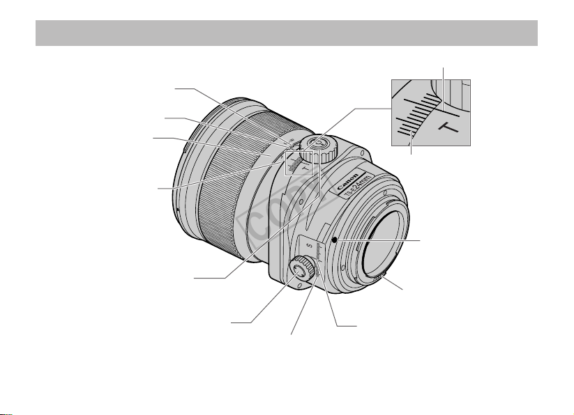
Nomenclature
11
4
COPY
Infrared index (→ 15)
Distance index
Distance scale (→ 8, 15)
Depth-of-Field scale (→ 15)
Tilt knob (→ 10)
Shift knob (→ 6, 12)
For detailed information, reference page numbers are provided in parentheses (→ **).
Shift scale
Tilt index
Tilt scale
Lens mount index (→ 8)
Contacts
Shift index
ENG-4
Page 6

Nomenclature
COPY
Tilt scale
Focusing ring (→ 8)
Hood mount (→ 17)
TS-E17mm f/4L
Tilt index
Tilt lock knob (→ 10)
Tilt-lock button (→ 10)
Lens
Lens cap mount (→ 7)
For detailed information, reference page numbers are provided in parentheses (→ **).
Filter mounting thread (→ 18)
Shift index
Rotation lock release
button
(→ 13)
TS rotation lock release
button (→ 14)
Shift scale
Shift lock knob (→ 12)
ENG-5
Page 7

About the Shift Knob Cap
COPY
Shifting will be easier if the supplied shift knob cap is mounted (p.4).
However, for EOS cameras with built-in flash, the cap will come in contact with the camera during
the lens’ mounting/detaching, or during shift/rotation operation. The shift knob cap is recommended
for use with EOS-1, EOS-1D, EOS-1Ds, and EOS 5D series.
Mounting screw
(Length 3mm)
Shift knob cap
Remove the shift knob
screw.
The screw (length 2.2mm) originally in the shift knob cannot be used to
keep the shift knob cap in place. Always use the supplied screw.
Use a watchmaker's screwdriver (Phillips head type) to remove or mount
screws.
Mount the cap by squeezing it into
the shift knob, and then fix it using
the supplied screw.
To remove the cap, remove the
screw and pull out the cap.
ENG-6
Page 8

Mounting/Removing the Lens Cap (TS-E17mm f/4L)
COPY
The lens of TS-E17mm f/4L protrudes from the front frame. To protect the lens, keep it covered with
the exclusive lens cap when not shooting.
24mm
m
m
17
TS-E
TS-E
LENS
ON
CAN
● Removing
To remove the cap, hold down the button on the side
and turn the cap in the direction of the arrow until the
position mark on the cap aligns with the red dot.
The removed lens cap can be hooked on the tripod
using the supplied strap.
● Attaching
To attach the cap, align the cap’s attachment position
mark with the red dot on the front of the lens, then
turn the cap as shown by the arrow until the lens’ red
dot is aligned with the cap’s stop position mark.
Do not use the strap to lift the lens while the lens
cap is attaching the lens. The lens may fall and
break.
ENG-7
Page 9

1.
COPY
Mounting and Detaching the Lens
2. Focusing
See your camera’s instructions for details on
mounting and detaching the lens.
● When mounting or detaching the lens, always
ensure that the tilt and shift scales are set to the
“0” position.
● After detaching the lens, place the lens with the
rear end up to prevent the lens surface and
contacts from getting scratched.
● If the contacts get soiled, scratched, or have
fingerprints on them, corrosion or faulty
connections can result. The camera and lens
may not operate properly.
● If the contacts get soiled or have fingerprints on
them, clean them with a soft cloth.
● If you remove the lens, cover it with the dust
cap. To attach it properly, align the lens mount
index and the index of the dust cap, and turn
clockwise. To remove it, reverse the order.
24mm
mm
24
TS-E
LENS
TS-E
CANON
Focus a TS-E lens by turning the focusing ring.
(Shots cannot be taken using the auto focus.)
● After using tilt or shift, readjust the focus.
● The distance scale is only valid when the tilt
scale is set to the “0” position.
For cameras which allow Live View shooting,
focusing using the LCD monitor’s magnified image
is recommended.
ENG-8
Page 10

3. Tilt Function
COPY
Tilting inclines the lens relative to the image plane. When the tilt scale is set to the “0” position, the
focusing and imaging planes are parallel. However, tilting puts the focusing plane at an angle to the
imaging plane.
● Example 1 ● Example 2
To shoot so that all of an extensive subject is in focus, you must normally use a small aperture to
obtain a large depth of field. But tilting allows you to keep all of the subject in focus even when there
is insufficient depth of field (Example 1). Or, by tilting in the opposite direction, you can focus on a
specific part of the subject (Example 2).
ENG-9
Page 11

Using Tilt
A
B
TS-E
24mm
CANON
LENS
TS-E
24
mm
COPY
Slide the tilt-lock button in the direction of
arrow A. Loosen the tilt lock knob by turning
it in the direction of arrow B.
Turn the tilt lock knob in the direction of the
arrow to lock the amount of tilt for the shot.
Turn the tilt knob to adjust the amount of tilt.
Focus the shot by turning the focusing ring.
To keep the tilt scale locked in the “0” position, slide
the tilt lock button in the direction of “LOCK”, then turn
the tilt lock knob in the direction of the arrow shown in
Step 3.
When you tilt the lens, sharp portions of the tilt
mechanism are exposed and care should be
taken to avoid touching these portions.
ENG-10
Page 12

4. Shift Function
COPY
Shifting moves the optical axis of the lens in parallel off the center of the imaging plane.
Shift can be used to good effect in the situations shown below.
● If you photograph a subject such as a
building with a normal lens, the top of
the building tapers away. But by placing
the camera parallel to the building and
shifting the lens, you can correct this
tapering effect.
● When you are shooting a reflective
subject, you can move the camera to a
position where the camera does not
appear in the shot and then use shift to
take the picture. This lets you keep the
camera out of the shot without having
to change the shot composition.
ENG-11
Page 13

Using Shift
COPY
24mm
mm
24
TS-E
TS-E
LENS
CANON
Loosen the shift lock knob
by turning it in the direction
of the arrow.
When you shift the lens, sharp portions of the shift mechanism are exposed and care should be taken to
avoid touching these portions. For EOS cameras with built-in flash, there may be contact with the lens while
Turn the shift knob to adjust
the amount of shift. Focus
the shot by turning the
focusing ring.
Turn the shift lock knob in
the direction of the arrow to
lock the amount of shift for
the shot.
you operate the shift function.
● With large amounts of shift, the amounts of peripheral light at the top and bottom or left and right sides of
the screen may differ, so shooting with a small aperture is recommended.
● The shift operation will be easier if the supplied cap is mounted on the shift knob (p.6).
ENG-12
Page 14

5. Rotation
COPY
The rotation function enables you to change the direction of tilt or
shift by rotating the tilt-shift mechanism.
With the lens mounted on the camera, push the rotation lock release
button towards the mount and then turn the tilt-shift mechanism.
● The rotation mechanism can be rotated through ±90°. The lens clicks every
30° and locks in place in the 90° position.
● When rotating the lens, set the tilt and shift scales to the “0” position.
● Note that rotating the tilt-shift mechanism quickly while pressing on the
rotation lock release button may cause the shift lock knob to strike your
fingers.
● Do not operate the shift function while operating the rotation function.
You may be injured by having your fingers caught.
● For EOS cameras with built-in flash, there may be contact with the lens
while you operate the rotation function.
In order to prevent shifts in position while shooting, shooting while
rotation is locked, or shooting per click position is recommended.
ENG-13
Page 15

Changing the Operation Direction of Tilt and Shift (TS rotation Function)
8.5
8
7
6
5
4
3
2
45678910 11 12
8.5
8
7
6
5
4
3
2
45678910 11 12
8.5
8
7
6
5
4
67891011 12
6.5
6
5
4
3
2
67891011 12
6.5
6
5
4
3
789101112
6.5
6
5
4
3
891011 12
COPY
By using the TS rotation function,
the relationship of the tilt and shift’s
operation direction can switch from
right angle to parallel.
Press the TS rotation lock release
button in the mounting direction while
the lens is mounted on the camera,
and then turn the tilt component.
● There are clicks at the 45° position, and
will be fixed in either the right angle or
parallel position.
When the tilt and shift are used in a parallel direction,
vignetting will occur in the areas marked in gray in the
following table.
TS-E17mm f/4L TS-E24mm f/3.5L II
Tilt and Shift direction
Imaging Area
Vertical
Horizontal
Diagonal
Tilt amount (Degree(s))
Shift amount (mm)
In order to prevent shifts in position while shooting, shooting
while TS rotation is locked, or shooting per click position is
recommended.
ENG-14
Page 16

6. Depth-of-Field Scale
22 2211 114
3
m
ft
1
3
2
5
0.5
1.5
0.7
4
4
COPY
(TS-E24mm f/3.5L II)
7. Infrared Index
(TS-E24mm f/3.5L II)
The depth of field is the distance in front of and
behind the plane of focus on the subject that
appears sharp. The depth of field is indicated by
the area between the depth-of-field scale lines
below the distance scale.
● The depth-of-field scale is only valid when the
tilt scale is set to the “0” position.
● The depth-of-field scale is an approximate
indicator.
2
1.5
0.5
22 2211 114
The infrared index corrects the focus setting
when using monochrome infrared film. Focus on
the subject in MF, then adjust the distance
setting by moving the focusing ring to the
corresponding infrared index mark.
Some EOS cameras cannot use infrared film. See
the instructions for your EOS camera.
● The infrared index position is based on a
wavelength of 800 nm.
● Be sure to observe the manufacturer’s
instructions when using infrared film.
● Use a red filter also when you take the picture.
0.7
5
3
3
1
4
ft
m
ENG-15
Page 17

8.
COPY
TS-E Tripod Adapter (Sold Separately)
9. Exposure
With some camera models, the tilt, shift and
rotation functions cannot be used when the
camera is mounted directly on a tripod. When
this happens, fit the optional TS-E tripod adapter
into the tripod mount socket on the camera
before mounting the camera on the tripod.
Shots can be taken using AE (automatic
exposure) as long as the tilt and shift scales are
set to the “0” position.
The use of AE is not recommended when the
lens is tilted or shifted as exposure errors may
result. It is recommended that you use the
exposure values when the tilt and shift scales
are set to the “0” position as a guide and then
take the shot with as many exposure settings as
possible.
ENG-16
Page 18

10. Hood (TS-E24mm f/3.5L II)
COPY
The EW-88B lens hood can keep unwanted light out of the lens, and also protects the lens from
rain, snow, and dust.
24mm
mm
24
TS-E
TS-E
LENS
CANON
mm
24
TS-E
LENS
CANON
position mark with the red dot on the front of the lens,
then turn the hood as shown by the arrow until the lens’
red dot is aligned with the hood’s stop position mark.
24mm
TS-E
The hood can be reverse-mounted on the lens for
storage.
When attaching or detaching the hood, grasp the base of the hood to turn it. To prevent deformation, do not
To attach the hood, align the hood’s attachment
grasp the rim of the hood to turn it.
● Cutting off harmful rays entering the lens by using both a hood as well as a piece of cardboard is
recommended.
● A hood is not available for TS-E17mm f/4L.
ENG-17
Page 19

11. Filters (Sold Separately)
22 2211 114
3
m
ft
1
3
2
5
0.5
1.5
0.7
4
COPY
(TS-E24mm f/3.5L II)
You can attach filters to the filter mounting
thread on the front of the lens.
● Only one filter may be attached.
● Use a polarizing Canon filter (82mm).
A filter cannot be used with TS-E17mm f/4L.
12. Infinity Compensation Mark
(TS-E24mm f/3.5L II)
Infinity compensation mark
Distance index
To compensate for shifting of the infinity focus
point that results from changes in temperature.
The infinity position at normal temperature is the
point at which the vertical line of the L mark is
aligned with the distance indicator on the
distance scale.
For accurate focusing of subjects at infinity, look
through the viewfinder’s magnified image* or the
LCD screen’s magnified image* while rotating the
focusing ring.
* For cameras with Live View shooting capability.
ENG-18
Page 20

13. Extension Tubes
COPY
(Sold Separately)
For TS-E24mm f/3.5L II, you can attach
extension tube EF12 II for magnified shots. The
shooting distance and magnification are shown
below.
Focusing Distance
Range (mm)
Close
EF12 II 182 198 0.85 0.51
distance
● The extension tubes EF12 II and EF25 II cannot
be used with TS-E17mm f/4L.
● Although extension tube EF25 II can be
attached on TS-E24mm f/3.5L II, it is not
recommended because the lens-to-subject
distance will be very short.
Long
distance
Magnification (×)
Close
distance
Long
distance
ENG-19
Page 21

Specifications
COPY
Focal Length/Aperture 17mm f/4 24mm f/3.5
Lens Construction 12 groups, 18 elements 11 groups, 16 elements
Minimum Aperture f/22 f/22
Angle of View
(Normal)
Min. Focusing Distance 0.25m (0.82ft.) 0.21m (0.69ft.)
Max. Magnification 0.14× 0.34×
Field of View 168 × 251mm (6.6 × 9.9inch) 72 × 107mm (2.8 × 4.2inch)
Tilt amount ±6.5° ±8.5°
Shift amount ±12mm
Tilt scale display 1° increments
Shift scale display 1mm increments
Rotation mechanism Locks at –90°, 0° and +90°, clicks every 30°
TS Rotation mechanism Locks at right angle and parallel, and clicks at 45°
Diagonal 104° 84°
Ver tical 70° 30’ 53°
Horizontal 93° 74°
TS-E17mm f/4L TS-E24mm f/3.5L II
ENG-20
Page 22

Specifications
COPY
Filter Diameter — 82mm
Max. Diameter and Length 88.9 × 106.7mm (3.5 × 4.2inch) 88.5 × 106.9mm (3.5 × 4.2inch)
Weight 820g (28.9oz) 780g (27.5oz)
Hood —EW-88B
Lens Cap Lens Cap 17 E-82
Case LP1219 LP1319
● The lens length is measured from the mount surface to the front end of the lens. Add 26mm to the
displayed length for TS-E17mm f/4L, and add 21.5mm to the displayed length for TS-E24mm
f/3.5L II when including the lens cap and dust cap.
● The size and weight listed are for the lens only, except as indicated.
● The EF1.4 × II/EF2 × II extenders, 250D/500D close-up lenses and the gelatin filter holders III/IV
cannot be used.
● Aperture settings are specified on the camera.
● All data listed is measured according to Canon standards.
● Product specifications and appearance are subject to change without notice.
TS-E17mm f/4L TS-E24mm f/3.5L II
ENG-21
Page 23

COPY
CT1-7587-001 © CANON INC. 2009 2009.7
 Loading...