

Page 1

Canon® A20
Oasis
Imaging Products Inc. Technical Support (8
00) 322
– 8992
ext 110
Canon
® A
-
20 Cartridge Remanufacturing Instructions
…
1 2
Remanufacturing Instructions
Reference Information:
OEM PN: F41-2302-120
OEM Yield: 3,000 @ 5.5%
Recommended Tools:
Tamperproof Torx® screw bit
Phillips head screwdriver
Pin puller
Flat head screwdriver
Approximate Remanufacturing Time:
20-25 min.
Instructions:
1. Remove the right side end cap (two tamperproof torx style screws -Fig. 1).
2. Remove the shutter actuating arm (Fig. 2).
3. Remove the color wheel (wiggling up, down and out- Fig. 2).
4. Remove the upper shutter spring (small one) and the hopper spring (Fig. 2).
5. Remove the two pins holding the waste bin in place, the one screw holding
the drum axle in, then the drum axle itself (you must hold the upper shutter-
bar flat to get the axle out), then remove the large pin holding the hopper in
place (Fig. 2).
6. Rotate the cartridge to the other end and remove the two pins holding the
waste bin in place and the one pin holding the hopper in place (Fig 3).
7. Remove the waste bin from the cartridge shell. Lift the waste bin by the right
side using a flat head screwdriver and jockey it out by lifting up and to the
right (Fig. 4).
Clean the waste bin.
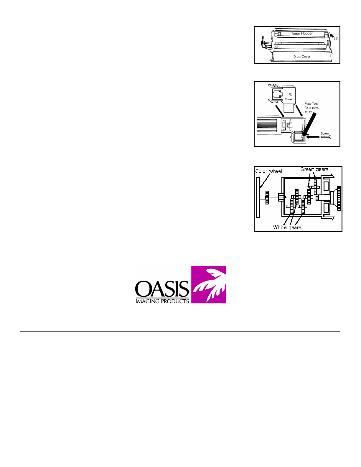
8. Remove the OPC drum. Move the drum cover towards you to expose the
drum and slide the drum to the left and lift out (Fig. 5). Clean, inspect, and
lubricate the drum and store in a dark place. Replace if necessary, if replace ment is required, then perform the following to remove the OEM gears:
a. Grasp the large gear and wiggle it off of the shaft.
d. Rap the rod down onto a hard surface to pop the plug out.
9. Remove the toner hopper from the cartridge shell (Fig. 6).
a. Clean the toner hopper of all old toner.
1. Remove toner hopper plug and dump residual toner.
2. Remove residual toner on the magnetic roller, place a vacuum nozzle
over the toner hopper hole and rotate the roller assembly.
insert the gapping strip between the magnetic roller and doctor blade,
and tighten the doctor blade (2 screws).
4. Recheck the gap to make sure nothing shifted during tightening.
a. Remove the cleaning blade (2 screws). Clean, inspect, and lubricate
the cleaning blade. Replace if necessary.
b. Dump the waste bin toner. Use a vacuum to remove any remaining
toner dust. Note: Be careful not to bend, crimp, tear or damage the
clear plastic strip collection/scavenger blade.
c. Install the cleaning blade.
Figure 4
b. Drill a hole in the end of the metal plug (where the gear was) large
enough for a 1/4” metal dowel to fit through.
c. Slide the metal dowel into the hole and up until it contacts the edge of
the drum plug.
e. Install the gear and plug onto the new drum.
Figure 5
3. Gap the doctor blade to .010”. Loosen the doctor blade (2 screws),
Figure 1
Figure 2
Figure 3
Page 2
b. Insert a toner hoper seal.
c. Fill the toner hopper with toner. Insert toner hopper plug.
9. Remove the corona assembly screw. Remove and clean the corona
assembly (Fig. 7). Pry the corona assembly to the left and lift it out. There
are two industry methods of cleaning this assembly, manual and ultrasonic.
The manual method requires using a Scotchbrite® pad. Use a small piece of
the pad and gently move the pad up and down the length of the wire. The
ultrasonic method requires placing the entire corona assembly in an ultrasonic
Figure 6
cleaner. Note: After removing the corona assembly two or three times, you
need to insure that the contact plate teeth for the corona assembly screw (Fig.
6) have not been spread too far.
11. Clean the shell of the cartridge to remove any toner dust.
12. Install the toner hopper into the cartridge shell (2 plastic pins).
13. Install the OPC drum.
14. Install the toner waste bin (4 plastic pins).
15. Install the smaller spring on the steel shutter and attach the larger toner
Figure 7
hopper spring.
Install drum axle.
17. Install the shutter actuating arm.
18. Install the color wheel. (Note: Make sure to reset the color wheel. Remove
color wheel cover (4 clasps). Lift the gear adjacent to the color wheel, and
turn the color wheel clockwise. Install the adjacent gear and replace cover (Fig 8).
19. Install end cap (2 torx style screws).
Figure 8
Oasis and You … Succeeding Together!
New Hampshire
(603) 880-3991
(800) 322-8992
Fax: (603) 598-4277
Illinois
(800) 322-8992
Fax: (972) 692-6976
© 1998 Oasis Imaging Products, Inc. Any attempt to reproduce any part of these instructions without the written consent of Oasis Imaging
Products, Inc, may result in legal action. All registered trademarks are the property of their respective owners.
Tennessee
(800) 322-8992
Fax: (901) 366-9756
California
(800) 322-8992
Fax: ((714) 908-7788
Texas
(800) 322-8992
Fax: (972) 692-6976
North Carolina
(800) 322-8992
Fax: (603) 386-7575
Canada
(800) 322-8992
Fax: (972) 692-6976
Europe
Netherlands
011-31-24-388-2233
Fax: 011-31-24-355-7373
South America
(800) 322-8992
International:
(603) 880-1552
Fax: (603) 386-7575
 Loading...