

Canon Paper Folding Unit-J1 Service Manual

Paper Folding Unit-J1
Service Manual
Revision 3.0

1x
1x
Introduction
Introduction
Important Notices
Application
This manual has been issued by Canon Inc. for qualified persons to learn technical theory, installation, maintenance, and repair
of products.
This manual covers all localities where the products are sold. For this reason, there may be information in this manual that does
not apply to your locality.
Corrections
This manual may contain technical inaccuracies or typographical errors due to improvements or changes in products.
When changes occur in applicable products or in the contents of this manual, Canon will release technical information as the
need arises. In the event of major changes in the contents of this manual over a long or short period, Canon will issue a new
edition of this manual.
The following paragraph does not apply to any countries where such provisions are inconsistent with local law.
Trademarks
The product names and company names used in this manual are the registered trademarks of the individual companies.
Copyright
This manual is copyrighted with all rights reserved. Under the copyright laws, this manual may not be copied, reproduced or
translated into another language, in whole or in part, without the consent of Canon Inc.
Copyright CANON INC. 2015
Caution
Use of this manual should be strictly supervised to avoid disclosure of confidential information.
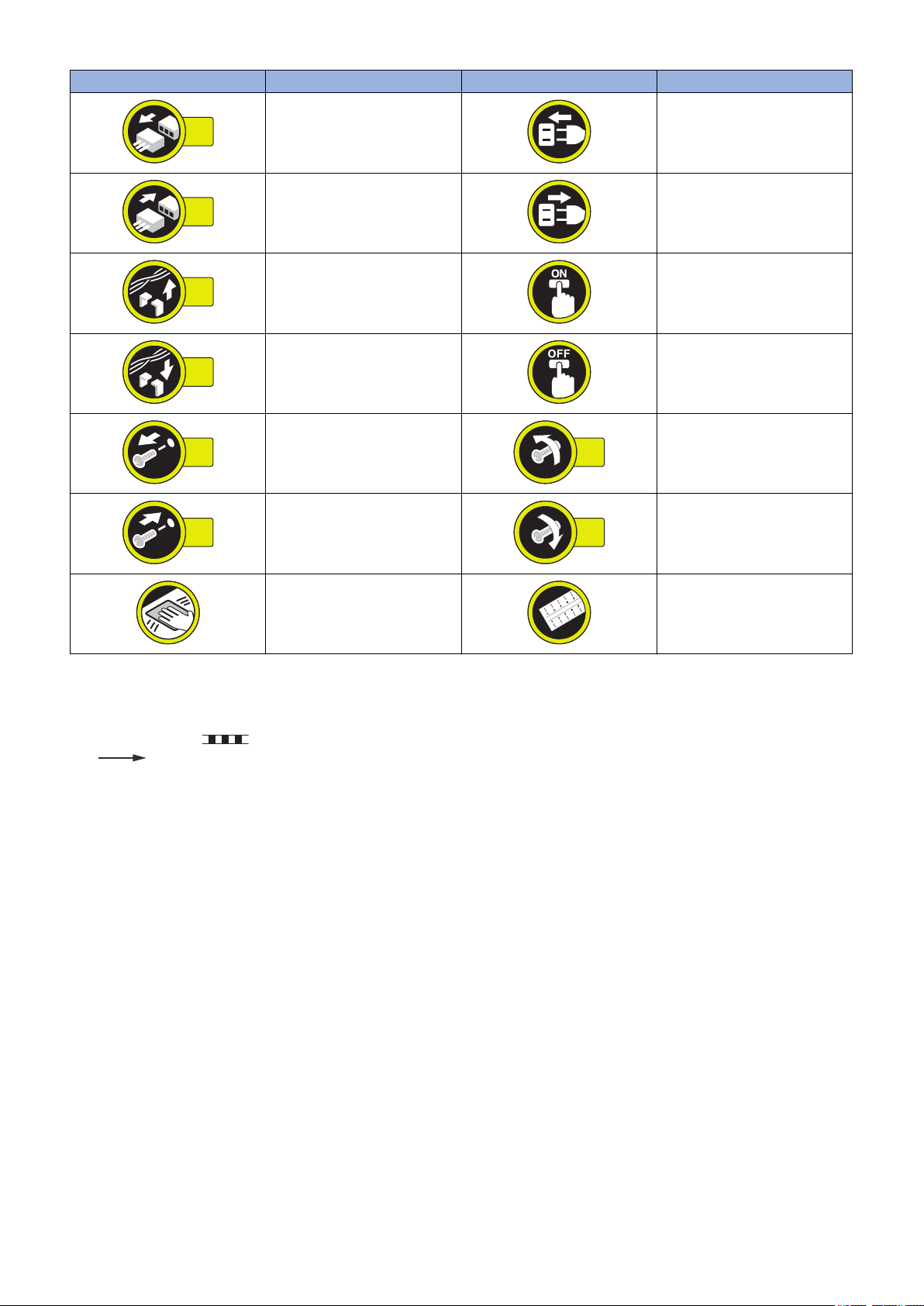
Explanation of Symbols
The following symbols are used throughout this Service Manual.
Symbols Explanation Symbols Explanation
Check.
Remove the claw.
Check visually.
Check a sound. Push the part.
Insert the claw.
1x
1x
1x
1x
1x
1x
1x
1x
Introduction
Symbols Explanation Symbols Explanation
Disconnect the connector. Connect the power cable.
Connect the connector. Disconnect the power cable.
Remove the cable/wire from the
cable guide or wire saddle.
Install the cable/wire to the cable
guide or wire saddle.
Remove the screw.
Install the screw.
Cleaning is needed. Measurement is needed.
The following rules apply throughout this Service Manual:
1. Each chapter contains sections explaining the purpose of specific functions and the relationship between electrical and
mechanical systems with reference to the timing of operation.
In the diagrams, represents the path of mechanical drive; where a signal name accompanies the symbol, the arrow
indicates the direction of the electric signal.
The expression "turn on the power" means flipping on the power switch, closing the front door, and closing the delivery unit
door, which results in supplying the machine with power.
2. In the digital circuits, '1' is used to indicate that the voltage level of a given signal is "High", while '0' is used to indicate "Low".
(The voltage value, however, differs from circuit to circuit.) In addition, the asterisk (*) as in "DRMD*" indicates that the DRMD
signal goes on when '0'.
In practically all cases, the internal mechanisms of a microprocessor cannot be checked in the field. Therefore, the operations
of the microprocessors used in the machines are not discussed: they are explained in terms of from sensors to the input of
the DC controller PCB and from the output of the DC controller PCB to the loads.
The descriptions in this Service Manual are subject to change without notice for product improvement or other purposes, and
major changes will be communicated in the form of Service Information bulletins.
All service persons are expected to have a good understanding of the contents of this Service Manual and all relevant Service
Information bulletins and be able to identify and isolate faults in the machine.
Turn on the power.
Turn off the power.
Loosen the screw.
Tighten the screw.

Contents
Contents
Safety Precautions...............................................................................................1
Points to Note About Turning Off the Main Power Switch...................................................................2
Notes Before Servicing........................................................................................................................2
Points to Note at Cleaning...................................................................................................................2
Notes On Assembly/Disassembly....................................................................................................... 2
1. Product Overview.............................................................................................3
Outline.................................................................................................................................................4
Features...............................................................................................................................................4
Specifications...................................................................................................................................... 5
Specifications....................................................................................................................................... 5
Others..................................................................................................................................................5
Fold Accuracy.......................................................................................................................................5
Names of Parts....................................................................................................................................9
External View........................................................................................................................................9
Cross Section View............................................................................................................................. 11
2. Technical Explanation................................................................................... 12
Basic Configuration........................................................................................................................... 13
Functional Configuration......................................................................................................................13
Electric Circuit Overview......................................................................................................................13
Component Configuration.................................................................................................................... 14
Drive Configuration..............................................................................................................................16
Operation Mode Overview................................................................................................................... 16
Controls.............................................................................................................................................25
Outline of operations........................................................................................................................... 25
Detecting Jams................................................................................................................................... 52
Power Supply..................................................................................................................................... 54
Upgrading..........................................................................................................................................55
Upgrading...........................................................................................................................................55
3. Periodical Service.......................................................................................... 56
List of Work for Scheduled Servicing................................................................................................ 57
4. Disassembly/Assembly................................................................................. 59
List of Parts....................................................................................................................................... 60
List of Parts........................................................................................................................................ 60
Consumable Parts Requiring Periodic Replacement and Cleaning Points............................................... 61
List of Motors / PCBs / Others..............................................................................................................62
List of Sensors....................................................................................................................................63
External / Internal Covers..................................................................................................................64
Removing the Rear Upper Cover..........................................................................................................64
Removing the Rear Cover....................................................................................................................64
i

Contents
Open the Front cover...........................................................................................................................64
Open the Feed Guide..........................................................................................................................65
Removing the Front Cover...................................................................................................................65
Removing the Front Lower Cover.........................................................................................................66
Removing the Rear Inner Cover...........................................................................................................66
Removing the Front Inner Cover.......................................................................................................... 68
Removing the Right Inner Cover.......................................................................................................... 70
Main Units......................................................................................................................................... 71
Drawing out the Folding Unit................................................................................................................71
Removing the Power Supply Unit Base.................................................................................................71
Consumable Parts Requiring Periodic Replacement and Cleaning Points....................................... 73
Removing the Folding Position Adjustment Feed Clutch (CL3)............................................................... 73
Removing the Folding Position Adjustment Back Clutch (CL4)............................................................... 73
Removing the Through/Fold Branch Solenoid(SOL2).............................................................................74
Removing the Fold/Separation Solenoid (SOL3)................................................................................... 75
Removing the Folding Tray Flapper Solenoid (SOL4)............................................................................ 76
Removing the C-fold Stopper Solenoid (SOL5)......................................................................................77
Removing the Through-pass Inlet Antistatic Needle...............................................................................77
Removing the Through-pass Outlet Antistatic Needle............................................................................ 78
Motors............................................................................................................................................... 80
Removing the Folding Tray Motor (M7).................................................................................................80
Removing the Upper Stopper Motor (M8)..............................................................................................80
Removing the C-fold Stopper Motor (M9)..............................................................................................81
Removing the Leading Edge Pushing Guide Motor (M10)...................................................................... 81
Removing the Inlet Motor 2 (M12)........................................................................................................ 82
Removing the Outlet Motor 2 (M13)......................................................................................................83
Removing the Outlet Motor 1 (M14)......................................................................................................84
Removing the Folding Position Adjustment Motor (M15)........................................................................ 85
PCBs................................................................................................................................................. 86
Removing the Folder Controller PCB....................................................................................................86
Others................................................................................................................................................88
Removing the Delivery Feed Roller...................................................................................................... 88
5. Adjustment..................................................................................................... 89
Overview........................................................................................................................................... 90
Adjustment and Functional Setting in Service Mode.............................................................................. 90
Basic Adjustment................................................................................................................................ 91
Action on parts replacement.................................................................................................................91
Major Adjustment.............................................................................................................................. 93
Z-fold/Outer three-fold (1st fold) inclination adjustment (Registration roller inclination adjustment)............ 93
Z-fold/Outer three-fold/C-fold (2nd fold) inclination adjustment (Leading edge stopper inclination
adjustment)..................................................................................................................................... 96
Z-fold/Two-fold paper skew adjustment (Delivery guide protective sheet protrusion adjustment)...............99
C-fold/Two-fold/Four-fold (1st fold) inclination adjustment (Trailing edge stopper inclination).................. 101
Action on parts replacement............................................................................................................105
Actions when Replacing the Folder controller PCB.............................................................................. 105
6. Installation.................................................................................................... 107
How to Check this Installation Procedure........................................................................................108
ii

Contents
Symbols in the Illustration.................................................................................................................. 108
Checking before Installation............................................................................................................109
Checking the Installation Space..........................................................................................................109
Check Items when turning OFF the Main Power..................................................................................109
Points to Note before Installation........................................................................................................ 109
Installation Order of Options...............................................................................................................109
Product Name...................................................................................................................................113
Unpacking....................................................................................................................................... 114
Unpacking Procedure........................................................................................................................ 114
Checking the Contents....................................................................................................................119
Installation Outline Drawing................................................................................................................120
Installation Procedure......................................................................................................................124
Preparation for Installation on Upstream Equipment............................................................................ 124
Connecting to Upstream Equipment................................................................................................... 130
Connecting the Interface Cable.......................................................................................................... 131
Connecting the Intermediate Power Cable.......................................................................................... 133
Connecting the Shunt Cable...............................................................................................................135
Attaching the Label............................................................................................................................139
Adjustment...................................................................................................................................... 141
Height/ Inclination Checking and Adjustment.......................................................................................141
Making Checks after Completion of Installation.............................................................................. 150
Disposal Parts...................................................................................................................................150
Operation Checks..............................................................................................................................151
APPENDICES....................................................................................................152
Service Tools...................................................................................................................................153
Special Tools.................................................................................................................................... 153
Solvents and Oils.............................................................................................................................. 153
General Circuit Diagram..................................................................................................................154
General Circuit Diagram 1/5...............................................................................................................154
General Circuit Diagram 2/5...............................................................................................................155
General Circuit Diagram 3/5...............................................................................................................156
General Circuit Diagram 4/5...............................................................................................................157
General Circuit Diagram 5/5...............................................................................................................158
iii

Safety Precautions
Points to Note About Turning Off the
Main Power Switch............................2
Notes Before Servicing......................... 2
Points to Note at Cleaning.................... 2
Notes On Assembly/Disassembly.........2
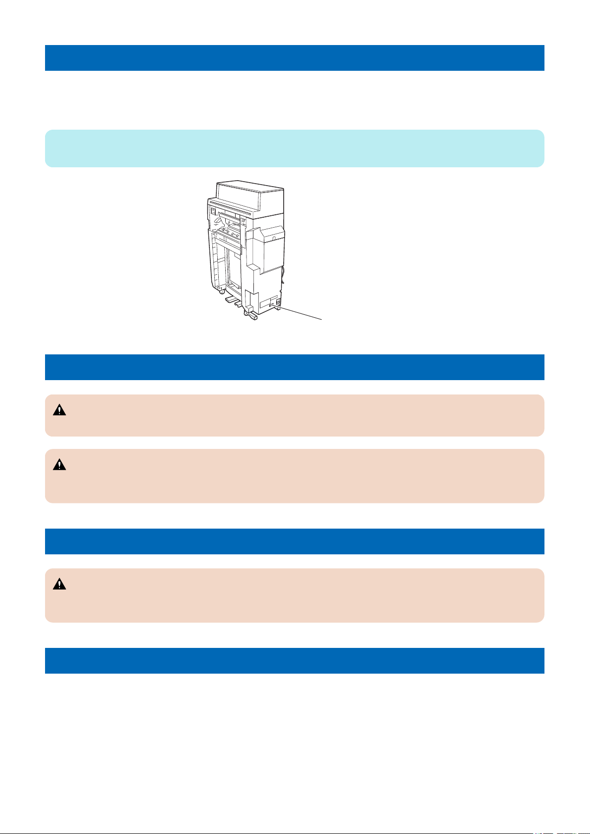
Leakage Breaker
Safety Precautions
Points to Note About Turning Off the Main Power Switch
This equipment does not have a main power switch, but it has only a leakage breaker.
The power supply of this equipment operates in synchronization with ON/OFF of the power supply of the finisher.
The leakage breaker detects overcurrent and power leakage.
NOTE:
Explain to the customer that the leakage breaker must be checked once a month.
Notes Before Servicing
CAUTION:
At servicing, be sure to turn off the power source according to the specified steps and disconnect the power plug.
CAUTION:
Do not turn off the power switch when downloading is under way. Turning off the main power switch while downloading is
under way can disable the machine.
Points to Note at Cleaning
CAUTION:
When performing cleaning using organic solvent such as alcohol, be sure to check that the component of solvent is
vaporized completely before assembling.
Notes On Assembly/Disassembly
Follow the items below to assemble/disassemble the device.
1. Disconnect the power plug to avoid any potential dangers during assembling/disassembling works.
2. If not specially instructed, reverse the order of disassembly to reinstall.
3. Ensure to use the right screw type (length, diameter, etc.) at the right position when assembling.
4. To keep electric conduction, binding screws with washers are used to attach the grounding wire and the varistor. Ensure to
use the right screw type when assembling.
5. Unless it is specially needed, do not operate the device with some parts removed.
6. Never remove the paint-locked screws when disassembling.
2

1
Product Overview
Outline...................................................4
Specifications........................................5
Names of Parts..................................... 9

Outline
Features
• Five kinds of the paper folding processing are possible.
Fold types: Z-fold, C-fold, outer three-fold, four-fold, two-fold
1. Product Overview
4
1. Product Overview
Specifications
Specifications
Item Specification Remarks
Folding method Roller pressure contact method (demand process-
ing while feeding paper)
Folding mode Z-fold , C-fold, Outer three-fold, Four-fold, Two-fold • Z-fold, two-fold: Feeding to the finisher
Paper types Fold section:Thin paper, plain paper, recycled pa-
per, color paper, bond pape, coated paper ,Prepunched paper
Feed section:All substrates host machine supports
Paper size Z-fold A3, B4, A4R,
11X17, LGL, LTR-R
C-fold *1 A4R, LTR-R
Outer three-fold A4R, LTR-R
Four-fold A4R, LTR-R, LGL
Two-fold A4R, LTR-R
Feed section:All substrates host machine supports
Paper weighing capacity Z-fold, C-fold, Outer three-
fold, Two-fold
Four-fold
Feed section: 52 g/m2 to 350 g/m
Folding delivery tray
stacking capacity
C-fold Loading height:
Outer three-fold Loading height: 60
Four-fold Loading height: 60
52g/m2 to 105g/m
52g/m2 to 90g/m
2
60mm
(equivalent to 40
sheets)
mm (equivalent to
40 sheets)
mm (equivalent to
25 sheets)
• C-fold, outer three-fold, four-fold: Delivering to the
folding delivery tray
2
2
Different depending on the host machine.
Equivalent of 81.4g/m2 paper.
*1: C-fold envelope standard sizes (reference)
A4R 120 mm x 235 mm, 105 mm x 235 mm, 120 mm x 235 mm
LTR-R COM10 (105 mm×241 mm)
Others
Item Specification
Dimensions (W x D x H) 336mm x 793mm x 1190mm
Weight Approx. 71 kg
Power supply Supplied from the connect machine
Power Consumption Standby: 24 W or less
Operating: 150 W or less
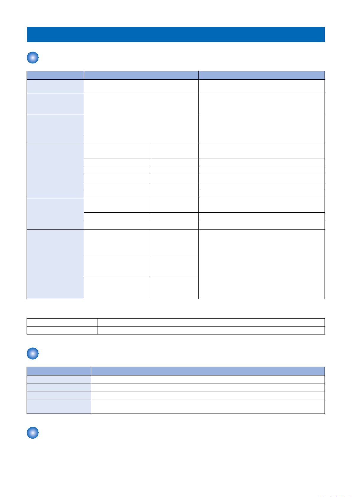
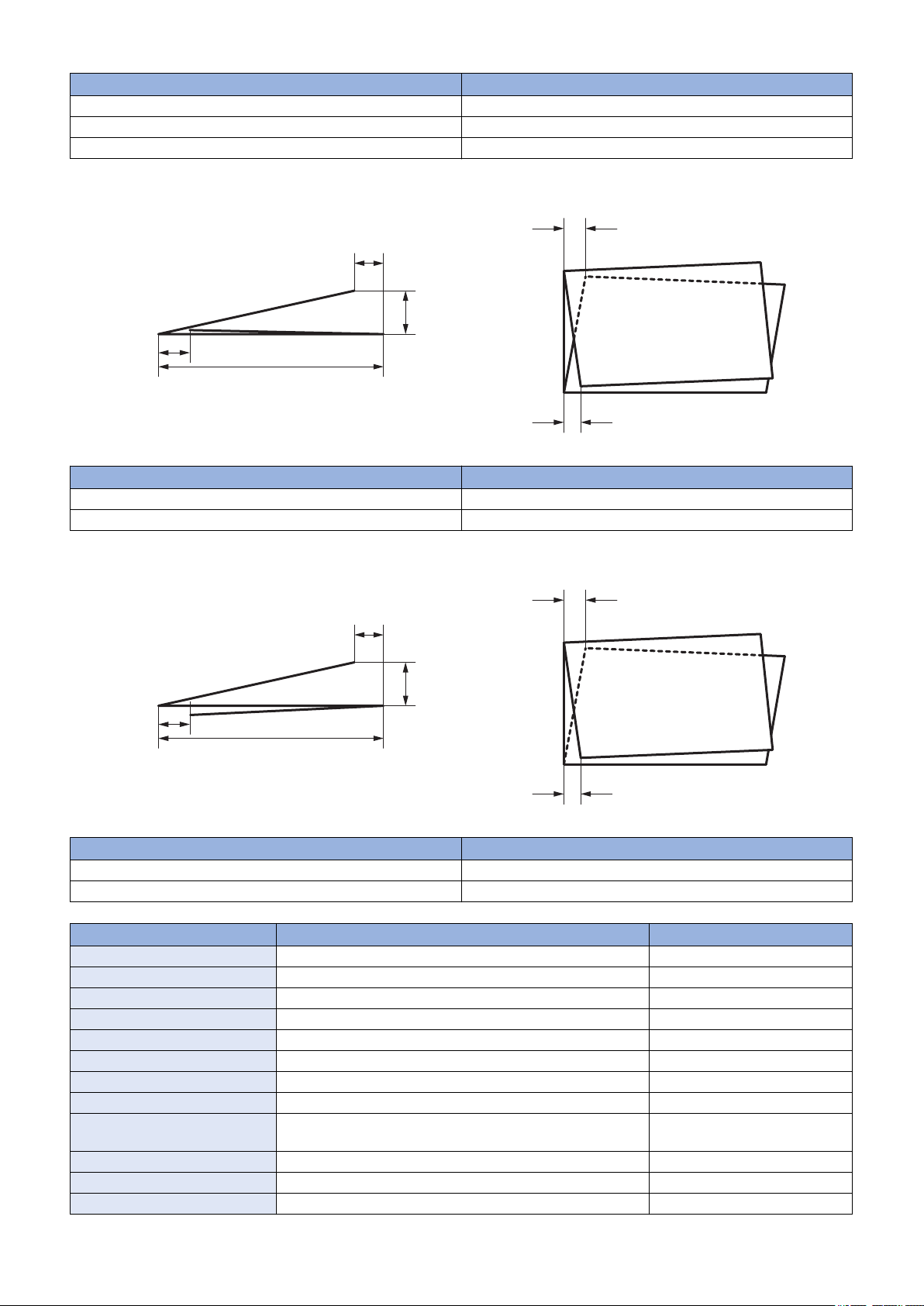
Fold Accuracy
Z-fold
5
Z2
Z3
Z4
Z1
Z5
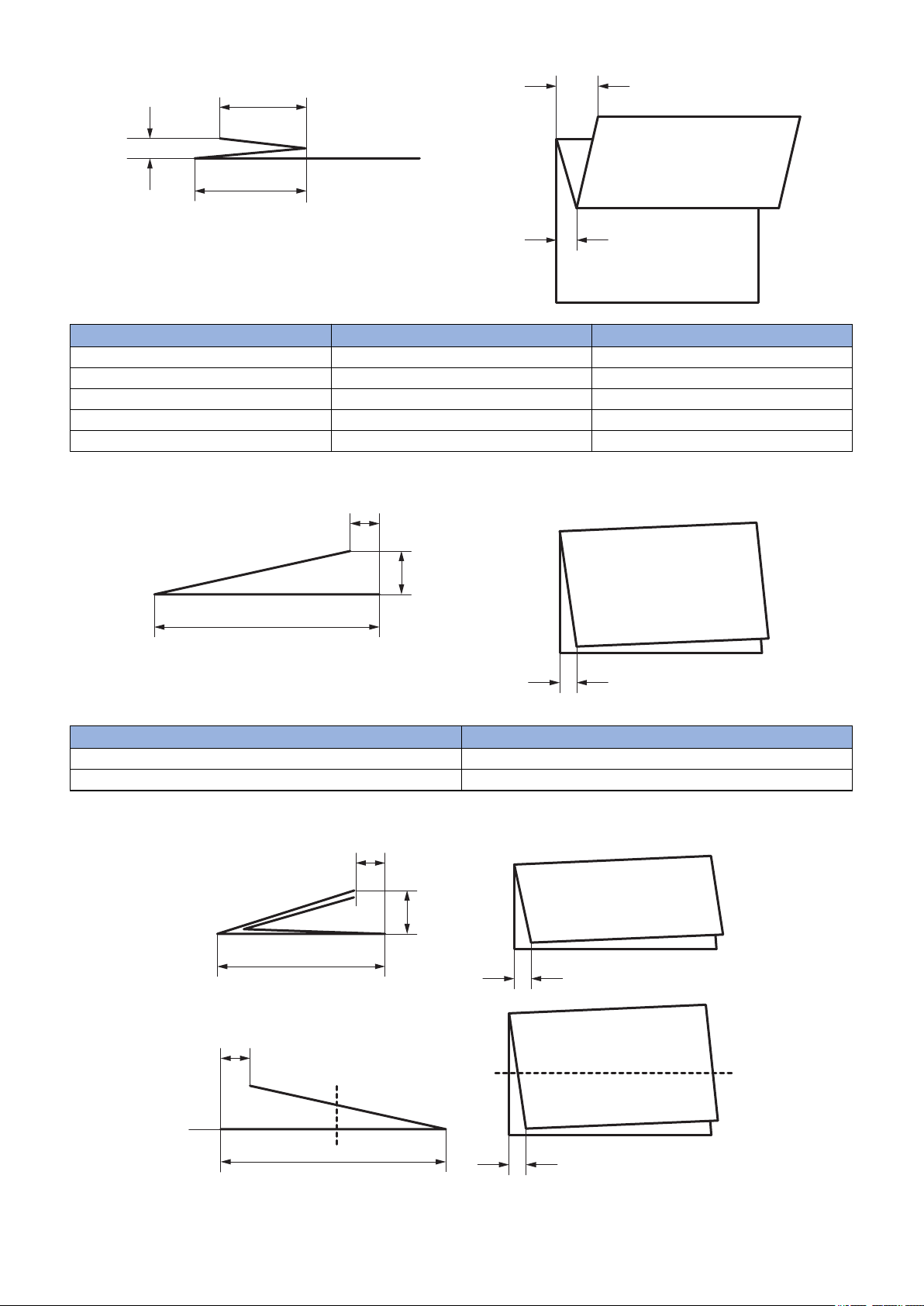
Two-fold
T2
T1
T4
T3
F2
F1
F4
F3
T2
T1
T3
1. Product Overview
Standard Z1 Dimensions Z2 Dimensions
A3 102.0 - 106.0mm 104.0 - 108.0mm
A4R 71.3 - 75.2mm 73.3 - 77.2mm
11x17 105.0 - 109.0mm 107.0 - 111.0mm
LGL 86.0 - 90.0mm 88.0 - 92.0mm
LTR-R 66.8 - 70.7mm 68.8 - 72.7mm
Four-fold
Standard T2 Dimensions
A4R 146.5 - 150.5mm
LTR-R 137.5 - 141.5mm
6
C-fold
C3
C1
C2
C6
C4
C5
O3
O1
O2
O6
O4
O5
1. Product Overview
Standard F2 Dimensions
A4R 73.8 - 77.7mm
LTR-R 69.3 - 73.2mm
LGL 88.5 - 92.5mm
Standard C3 Dimensions
A4R 98.5 - 102.5mm
LTR-R 92.6 - 96.5mm
Outer three-fold
Standard O3 Dimensions
A4R 98.5 - 102.5mm
LTR-R 92.6 - 96.5mm
Item Accuracy of A zone (15-27.5 deg C, 25-75%RH) Remarks
Z1 fold Line length/4-1±2.0mm
Z2 fold Line length/4+1±2.0mm User adjustment is available.
Z3/Z4 oblique fold Within ±1.5mm
Z5 fold height Within 15mm
T1 fold 0±2.0mm(3.5mm)* Reference value
T2 overall length Line length/2±2.0mm(3.5mm)* User adjustment is available.
T3 oblique fold ±1.5mm(2.5mm)*
T4 fold height Within 10mm
Z-fold, Two-fold paper delivery
performance
F1 fold 2.0±2.0mm(3.5mm)*
F2 overall length Line length/4+1.5±2.0mm User adjustment is available.
F3 oblique fold ±1.5mm(±2.0mm)*
Delivery Outlet side registration:Within ±3.5mm
Delivery Outlet Cross-feed: Within ±2.5mm/100mm
7

1. Product Overview
Item Accuracy of A zone (15-27.5 deg C, 25-75%RH) Remarks
F4 fold height Within 30mm Reference value
C1 fold 2.5±2.0mm
C2 fold 2.0±2.0mm
C3 overall length Line length/3+1.5 ±2.0mm
C4, C5 oblique fold Within ±1.5mm
C6 fold stacking capacity Max 40 sheets Equivalent of 80g/m2 paper.
O1 fold 2.5±2.0mm
O2 fold 2.0±2.0mm
O3 overall length Line length/3+1.5 ±2.0mm
O4, O5 oblique fold Within ±1.5mm
O6 fold stacking capacity Max 40 sheets Equivalent of 80g/m2 paper.
*The value in ( ) is for LGL.
8
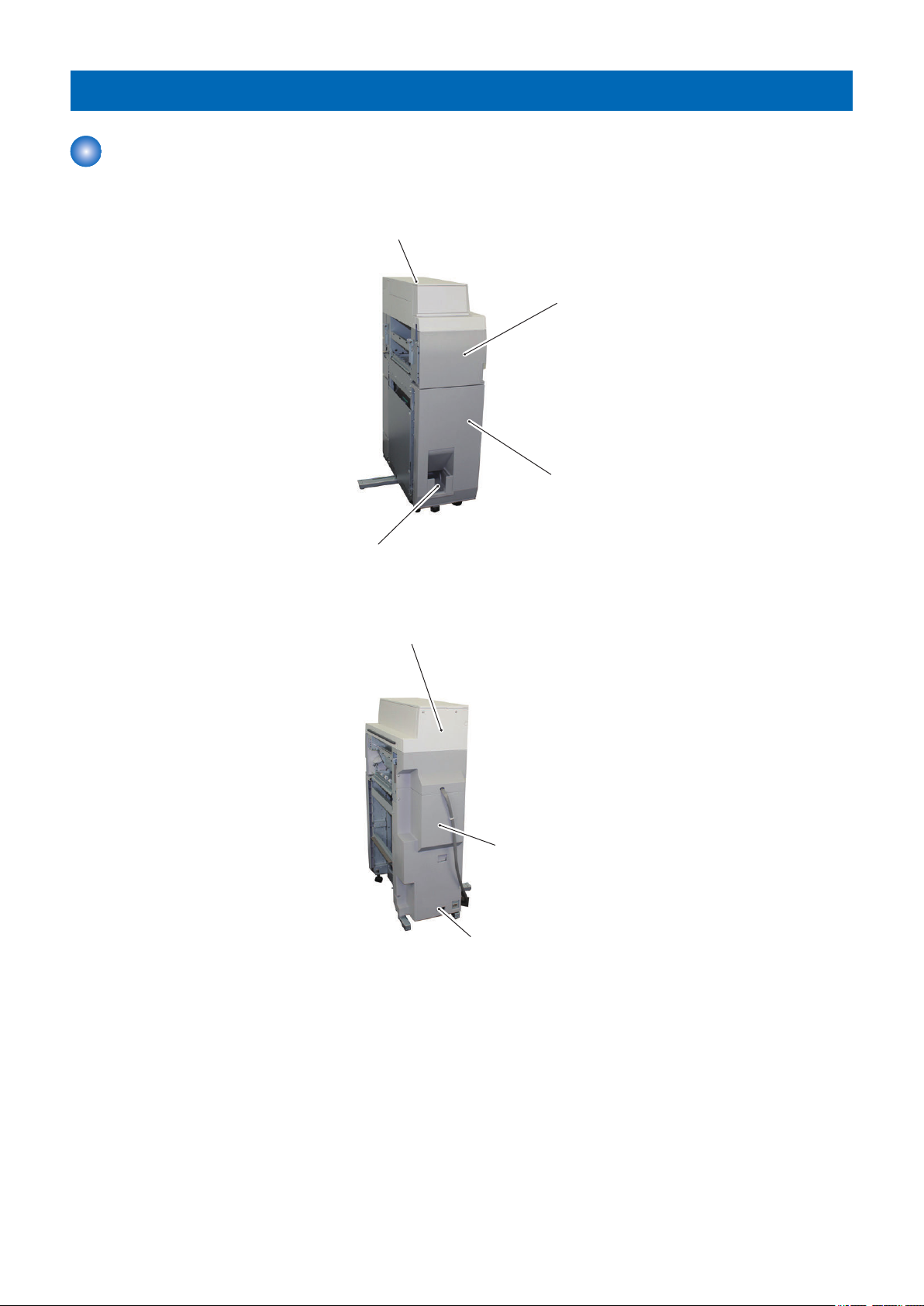
Names of Parts
Upper cover
Front cover
Folding delivery tray
Folding Unit
Leakage breaker
Rear cover
Rear Upper cover
External View
■ Front
1. Product Overview
■ Rear
9
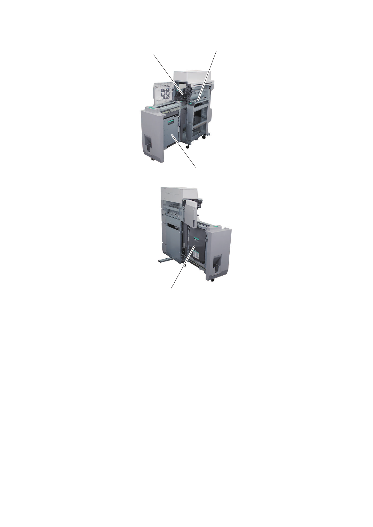
■ Internal
Feed guide
Right folding feed guide
Inlet feed guide
Left folding feed guide (left)
1. Product Overview
10
Cross Section View
[13]
[14]
[15]
[17]
[18]
[19]
[21]
[1]
[2]
[3]
[4]
[5]
[6]
[7]
[8]
[9]
[10]
[11]
[12]
[16]
[20]
1. Product Overview
[1] Folding/straight flapper [12] Folding tay flapper
[2] Inlet roller [13] Delivery feed roller 4
[3] Feed roller 1 [14] Folding roller 2
[4] Feed roller 2 [15] Registration roller
[5] Leading edge stopper [16] Delivery feed roller 5
[6] Folding roller1 [17] Trailing edge stopper
[7] Leading edge pushing guide [18] Delivery feed roller 6
[8] Folding roller3 [19] Delivery feed roller 7
[9] Delivery feed roller 1 [20] Delivery feed roller 8
[10] Delivery feed roller 2 [21] Delivery roller
[11] Delivery feed roller 3
11

Technical
2
Explanation
Basic Configuration.............................13
Controls...............................................25
Upgrading............................................55
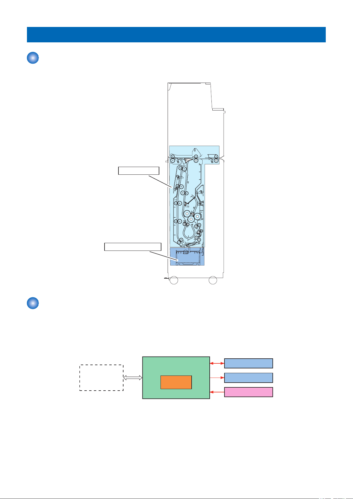
Basic Configuration
Folding feed unit
Folding tray delivery unit
Finisher
Folder controller PCB
Motor
Solenoid/Clutch
Sensor
CPU
Functional Configuration
This equipment is organized into two major blocks: folding feed unit and folding tray delivery unit.
2. Technical Explanation
Electric Circuit Overview
The operation sequence of this equipment is controlled by the folder controller PCB.
The folder controller PCB has a CPU.
The CPU on the controller controls DC loads such as motors and solenoids at the predetermined timings according to the signals
from the sensors and the finisher.
The folder controller PCB reports the information about the sensors to the finisher through serial communication.
13
Component Configuration
[13]
[14]
[15]
[17]
[18]
[19]
[21]
[1]
[2]
[3]
[4]
[5]
[6]
[7]
[8]
[9]
[10]
[11]
[12]
[16]
[20]
■ Roller Layout
2. Technical Explanation
[1] Folding/straight flapper [12] Folding tay flapper
[2] Inlet roller [13] Delivery feed roller 4
[3] Feed roller 1 [14] Folding roller 2
[4] Feed roller 2 [15] Registration roller
[5] Leading edge stopper [16] Delivery feed roller 5
[6] Folding roller1 [17] Trailing edge stopper
[7] Leading edge pushing guide [18] Delivery feed roller 6
[8] Folding roller3 [19] Delivery feed roller 7
[9] Delivery feed roller 1 [20] Delivery feed roller 8
[10] Delivery feed roller 2 [21] Delivery roller
[11] Delivery feed roller 3
■ Sensor Layout
It describes only sensors on the feed path.
14
S27
S32
S31
S21
S20
S30
S33
S22
2. Technical Explanation
S20 Inlet sensor
S21 Delivery sensor 2
S22 Delivery sensor 1
S27 Folding tray paper sensor
S30 Slowdown timing sensor
S31 Release timing sensor
S32 Folding position sensor
S33 Upper stopper paper sensor
15

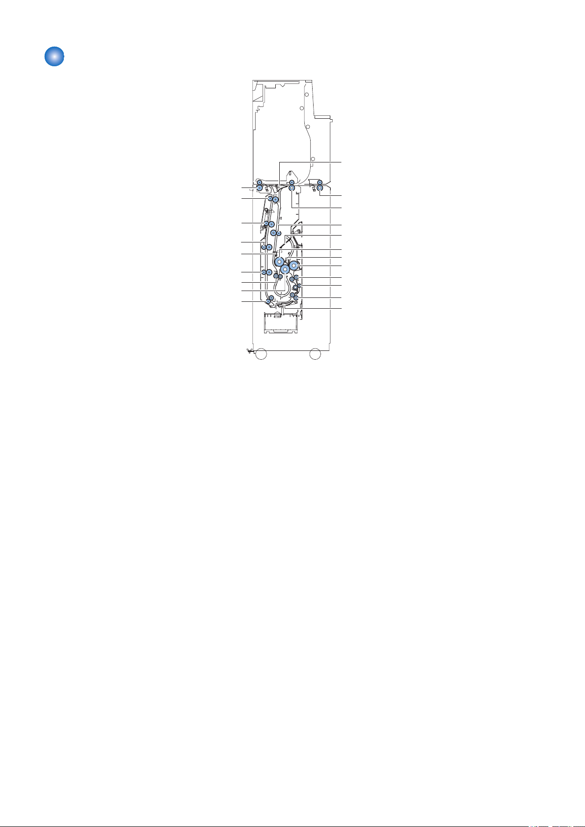
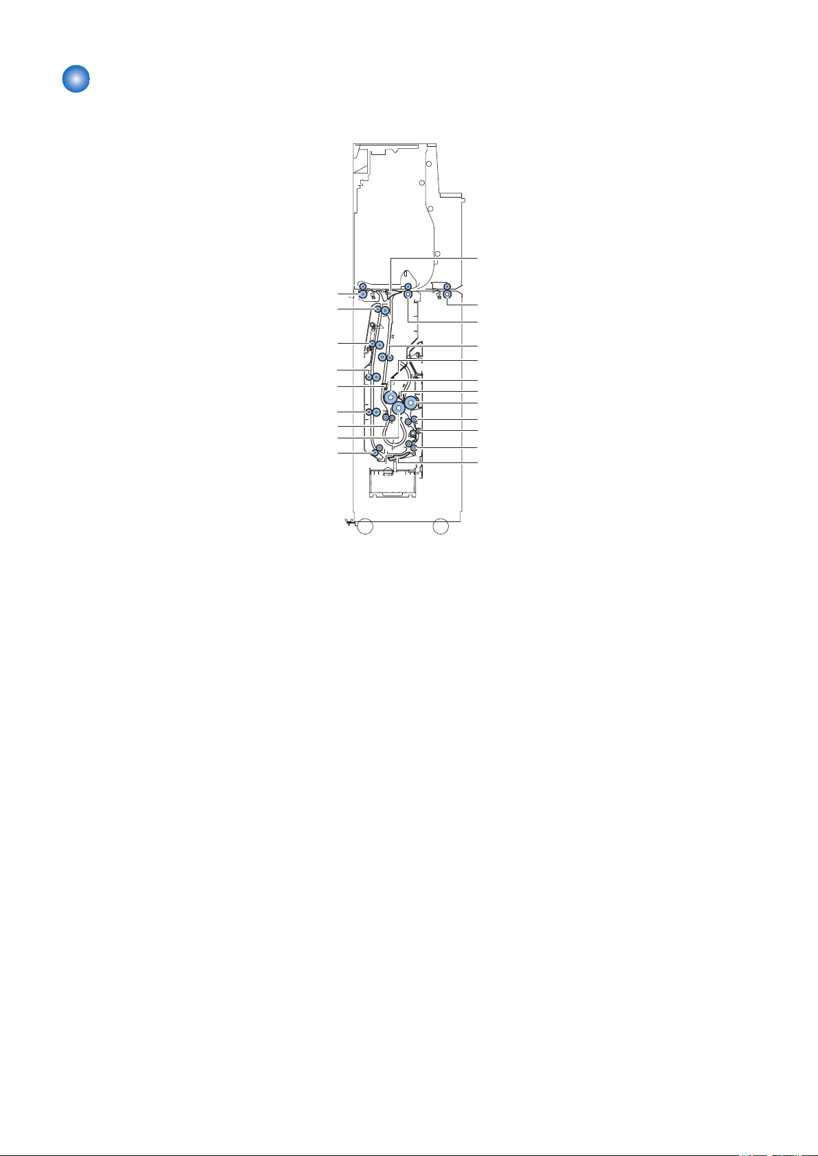
Drive Configuration
SOL2
M8
M12
M13
M15
CL4
CL3
M14
M7
M11
SOL4
M5
SOL3
M9
M10
2. Technical Explanation
M5 Inlet motor 1 M14 Outlet motor 1
M7 Folding tray motor M15 Folding position adjustment motor
M8 Upper stopper motor CL3 Folding position adjustment feed clutch
M9 C-fold stopper motor CL4 Folding position adjustment back clutch
M10 Leading edge pushing guide motor SOL2 Through/Fold Branch Solenoid
M11 Folding feed motor SOL3 Fold/Separation Solenoid
M12 Inlet motor 2 SOL4 Folding tray flapper solenoid
M13 Outlet motor 2
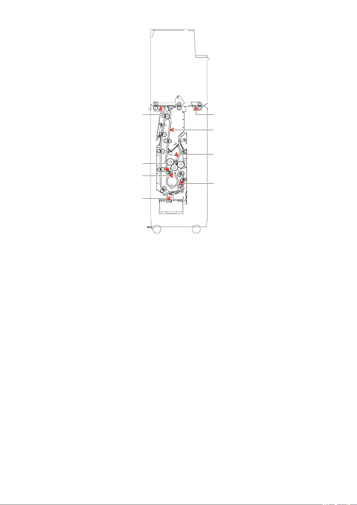
Operation Mode Overview
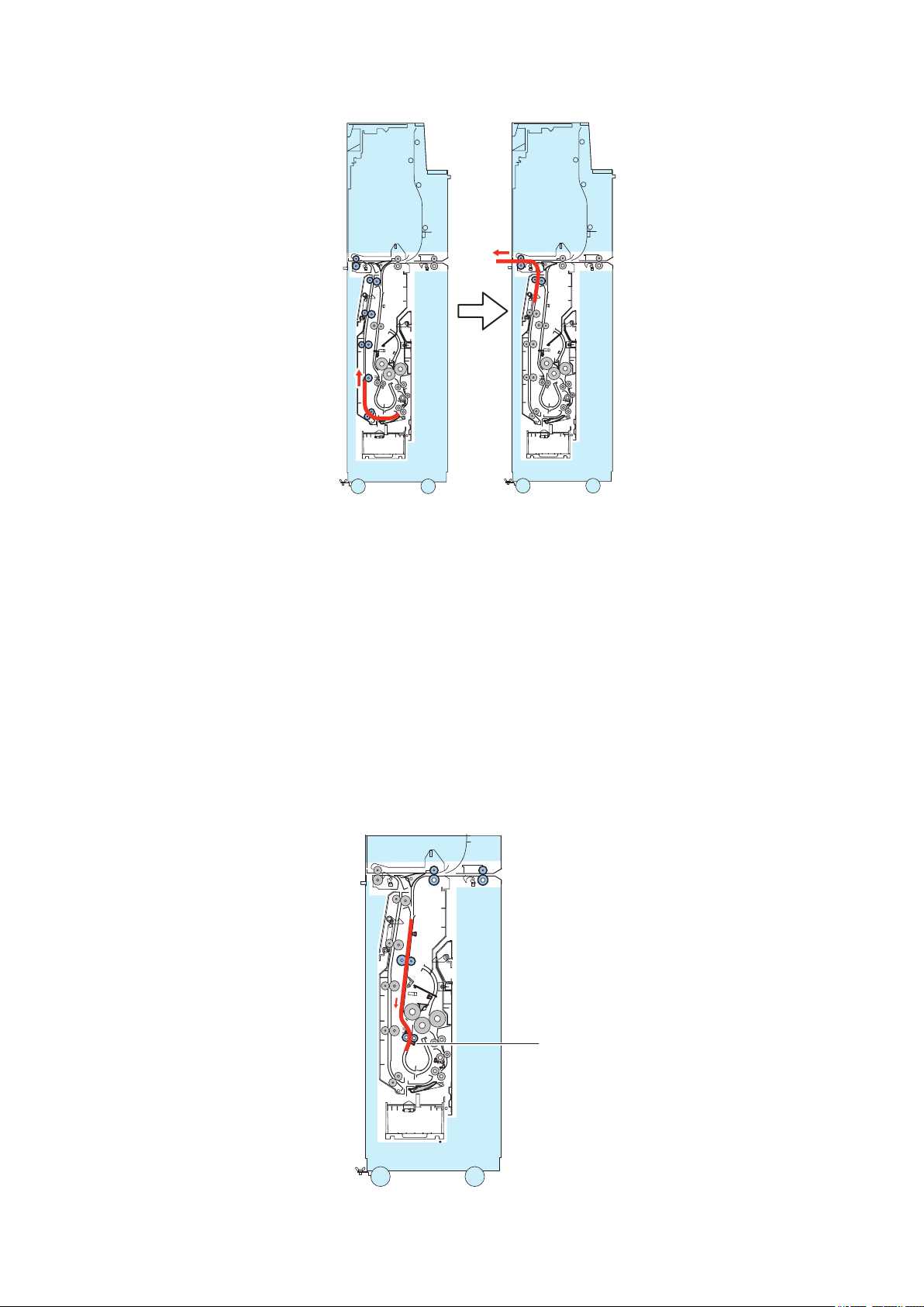
■ Z-fold operation
The Z-fold operation is carried out in the following order of steps:
1. Registration correction
2. Paper feeding operation
3. Folding operation
4. Delivery operation
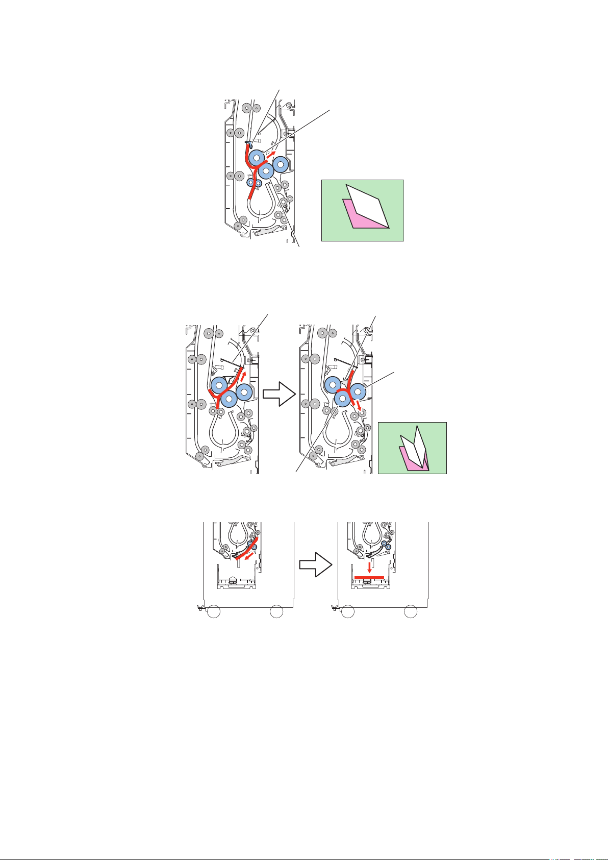
[Operation]
1. Registration correction
Stops the feeding of paper on the registration roller and forms a loop to correct the registration of the paper.
16
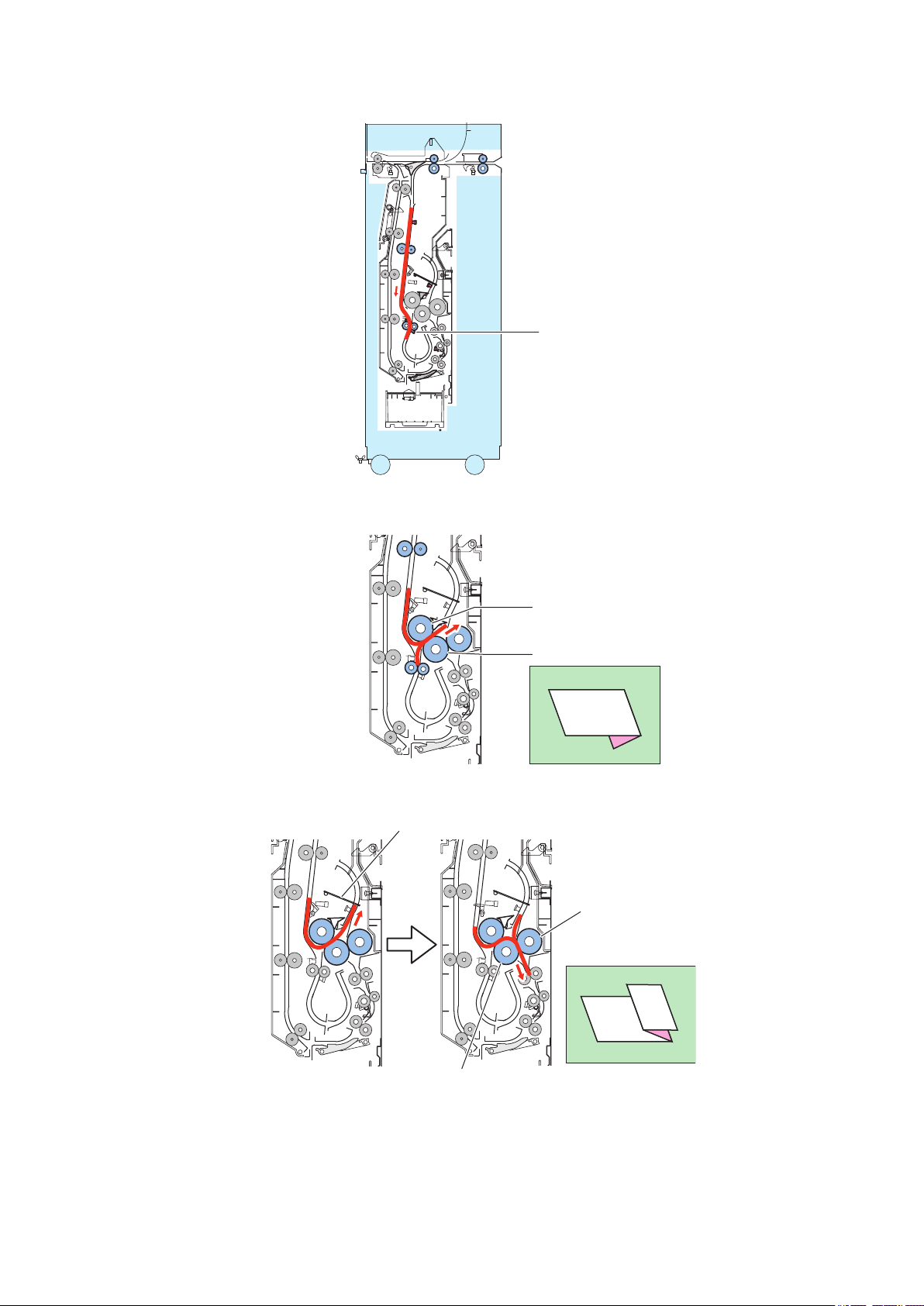
S32
Folding position
sensor
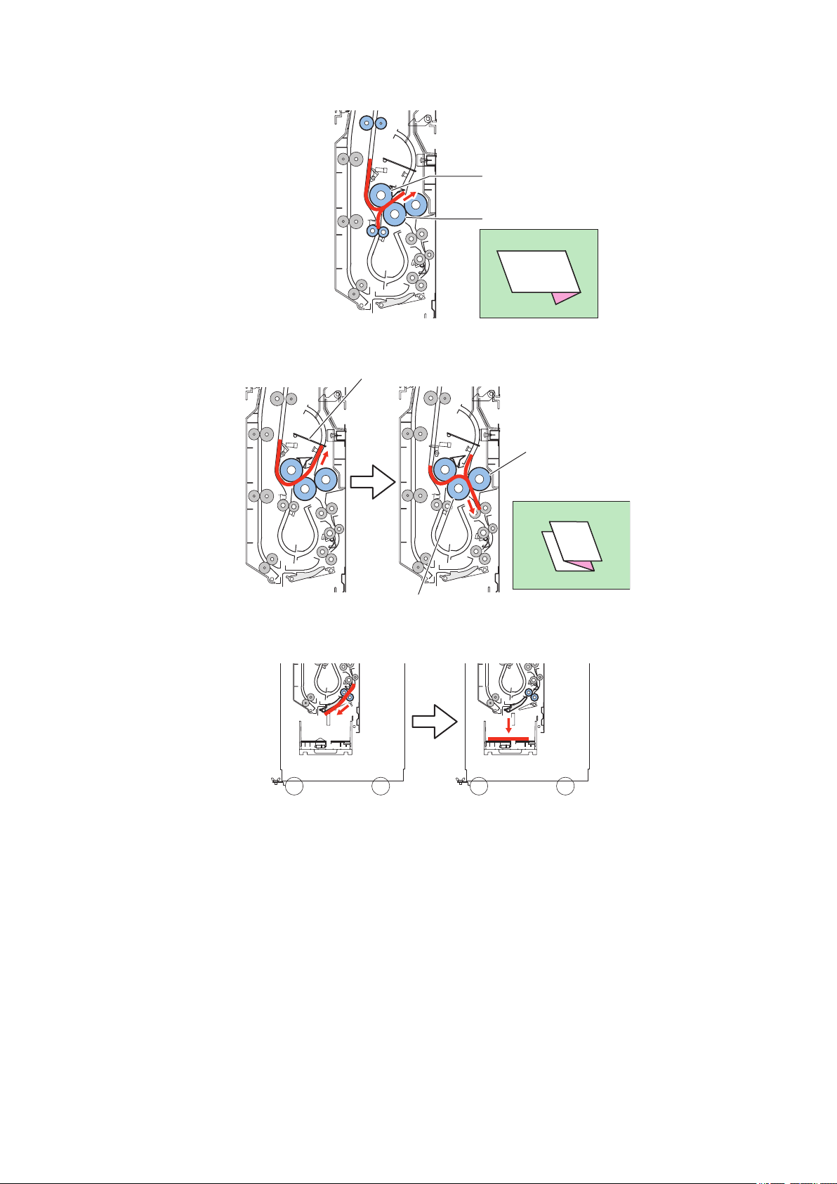
Folding roller 1
Folding roller 2
Folding roller 3
Folding roller 2
Leading edge stopper
2. Technical Explanation
2. Paper feeding operation
Feeds the paper by a specified time after the paper has passed through the folding position sensor (S32).
3. Folding operation
Gives the paper a first fold by the folding roller 1 and folding roller 2.
Gives the paper a second fold by the folding roller 2 and folding roller 3 as the paper bumps against the leading edge stopper.
17
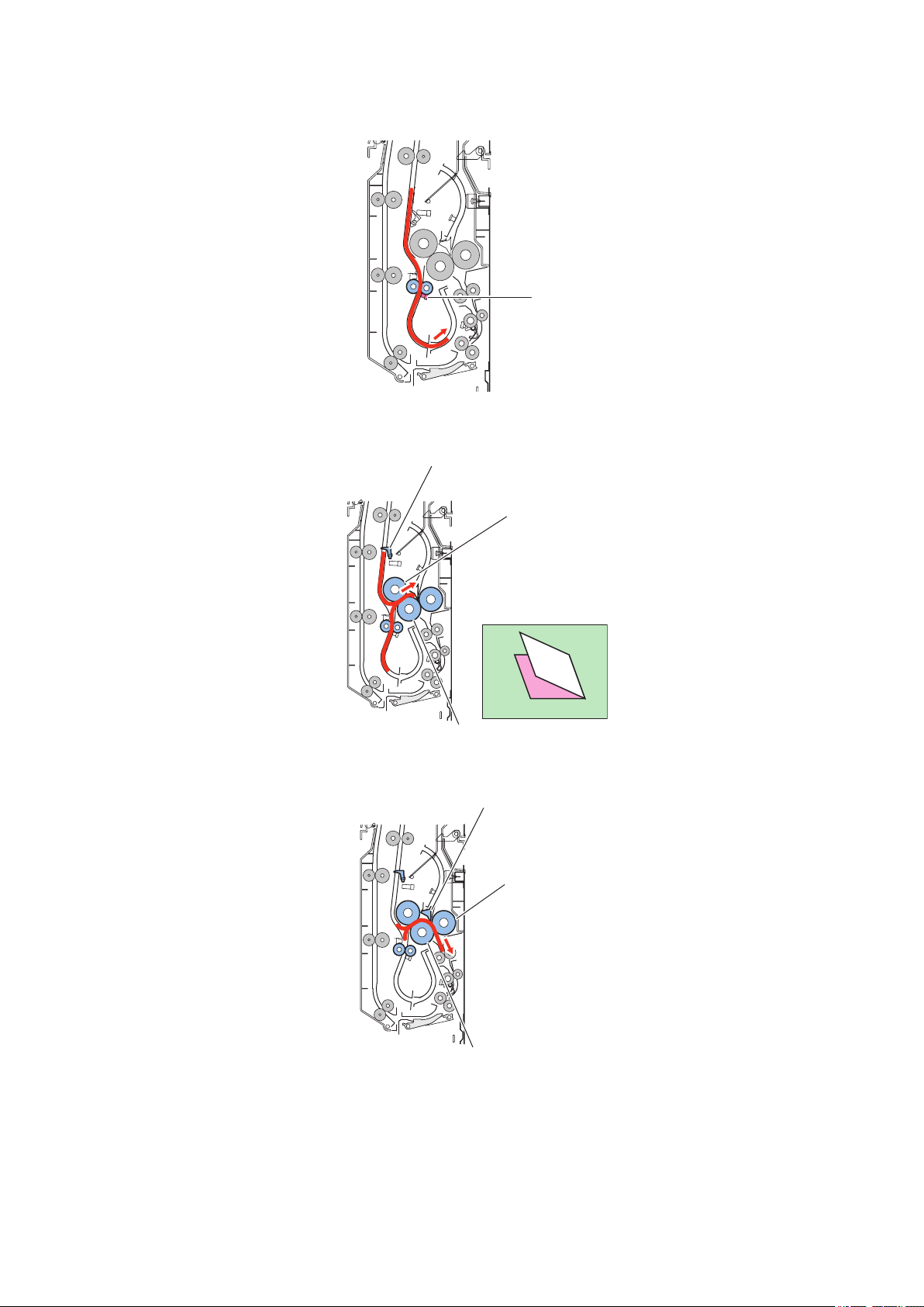
4. Delivery operation
S32
Folding position
sensor
Feeds the paper to the finisher through the delivery path.
2. Technical Explanation
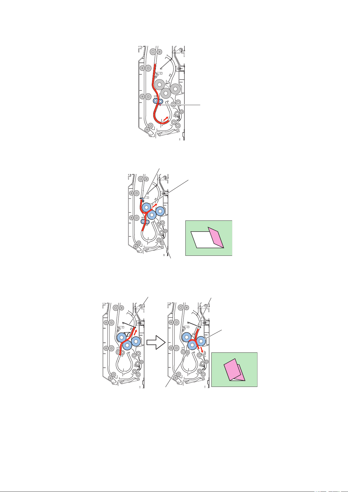
■ Outer three-fold operation
The outer three-fold operation is carried out in the following order of steps:
1. Registration correction
2. Paper feeding operation
3. Folding operation
4. Delivery operation
[Operation]
1. Registration correction
Stops the feeding of paper on the registration roller and forms a loop to correct the registration of the paper.
2. Paper feeding operation
Feeds the paper by a specified time after the paper has passed through the folding position sensor (S32). (Feeds the paper
longer length than the Z-fold operation: the position on one-third of the paper length)
18
Folding roller 1
Folding roller 2
Folding roller 3
Folding roller 2
Leading edge stopper
2. Technical Explanation
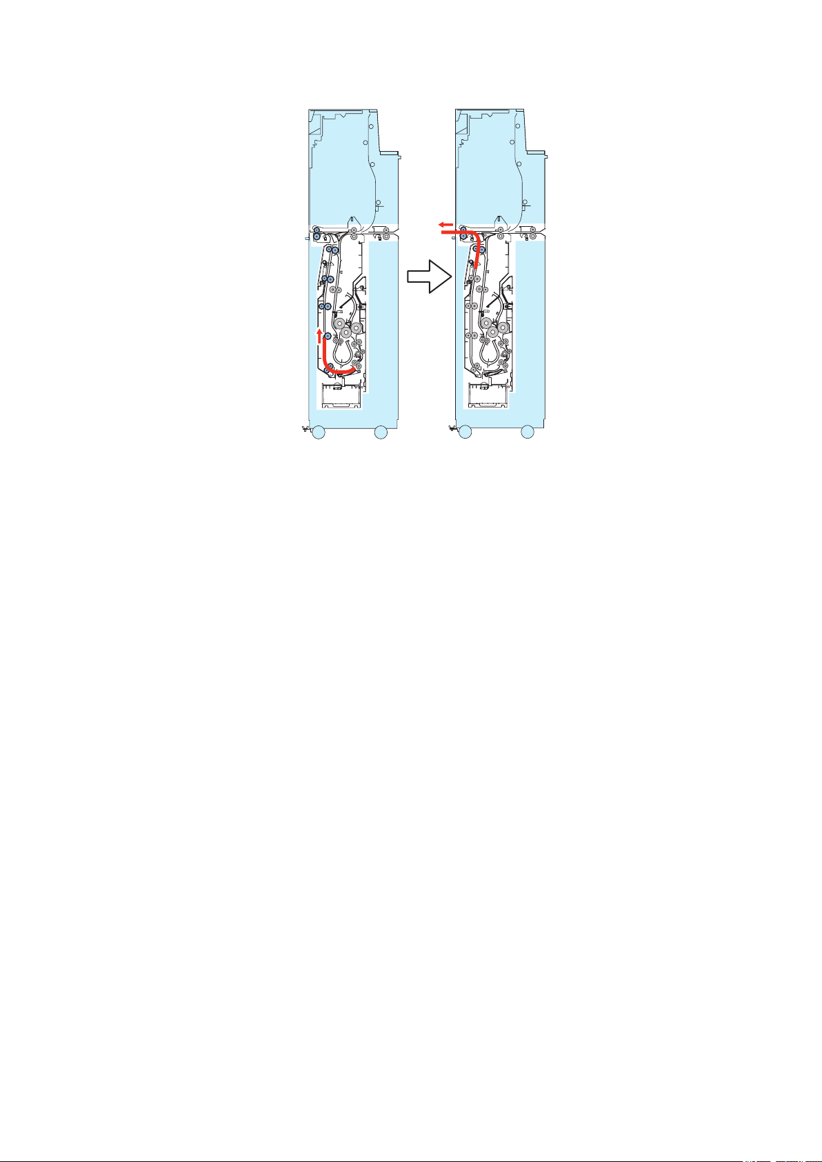
3. Folding operation
Gives the paper a first fold by the folding roller 1 and folding roller 2.
Gives the paper a second fold by the folding roller 2 and folding roller 3 as the paper bumps against the leading edge stopper.
4. Delivery operation
Delivers the paper to the folding delivery tray.
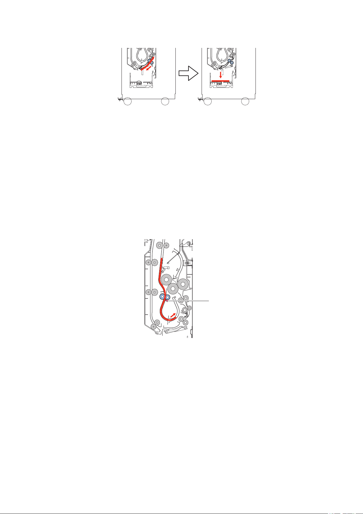
■ C-fold operation
The C-fold operation is carried out in the following order of steps:
1. Registration correction
2. Paper feeding operation
3. Folding operation
4. Delivery operation
[Operation]
1. Registration correction
Stops the feeding of paper on the registration roller and forms a loop to correct the registration of the paper.
19
S32
Folding position
sensor
Trailing edge stopper
Folding roller 1
Folding roller 2
Leading edge pushing guide
Leading edge stopper
Folding roller 3
Folding roller 2
2. Technical Explanation
2. Paper feeding operation
Feeds the paper by a specified time after the paper has passed through the folding position sensor (S32).
3. Folding operation
Gives the paper a first fold by the folding roller 1 and folding roller 2 as the paper bumps against the trailing edge stopper.
Gives the paper a second fold by the folding roller 2 and folding roller 3 and leading edge pushing guide as the paper bumps
against the leading edge stopper.
20
S32
Folding position
sensor
2. Technical Explanation
4. Delivery operation
Delivers the paper to the folding delivery tray.
■ Four-fold operation
The four-fold operation is carried out in the following order of steps:
1. Registration correction
2. Paper feeding operation
3. Folding operation
4. Delivery operation
[Operation]
1. Registration correction
Stops the feeding of paper on the registration roller and forms a loop to correct the registration of the paper.
2. Paper feeding operation
Feeds the paper by a specified time after the paper has passed through the folding position sensor (S32). (Feeds the paper
until the position on one-two of the paper length)
21
Folding roller 2
Folding roller 1
Trailing edge stopper
Folding roller 2
Folding roller 3
Leading edge pushing guide
Leading edge stopper
2. Technical Explanation
3. Folding operation
Gives the paper a first fold by the folding roller 1 and folding roller 2 as the paper bumps against the trailing edge stopper.
Gives the paper a second fold by the folding roller 2 and folding roller 3 with the leading edge pushing guide forcing the fold
into the paper as the paper bumps against the leading edge stopper.
4. Delivery operation
Delivers the paper to the folding delivery tray.
■ Two-fold operation
The twofold operation is carried out in the following order of steps:
1. Registration correction
2. Paper feeding operation
3. Folding operation
4. Delivery operation
[Operation]
1. Registration correction
Stops the feeding of paper on the registration roller and forms a loop to correct the registration of the paper.
22
S32
Folding position
sensor
Folding roller 2
Folding roller 1
Trailing edge stopper
Folding roller 2
Folding roller 3
Leading edge pushing guide
2. Technical Explanation
2. Paper feeding operation
Feeds the paper by a specified time after the paper has passed through the folding position sensor (S32). (Feeds the paper
until the position on one-two of the paper length)
3. Folding operation
Gives the paper a first fold by the folding roller 1 and folding roller 2 as the paper bumps against the trailing edge stopper.
Feeds the paper to the folding roller 2 and folding roller 3 along the leading edge pushing guide moved beforehand.
23
4. Delivery operation
Feeds the paper to the finisher through the delivery path.
2. Technical Explanation
24
 Loading...