


ENGLISH
日本語
Paper Deck Unit-B1/B2 Installation Procedure
ペーパーデッキユニット・B1/ B2 設置手順書
Follow the instructions herein when installing the equipment to its host machine.
本機を本体に接続する際は、以下の手順に従ってください。
PRINTED IN CHINA PUB No. FT1-0626-000
ENGLISH
日本語
Check items when Turning OFF the Main Power
2
How to Utilize This Installation Procedure
When Using the Contained Parts (Bundled Components
in the Shipping Carton)
A syambole is described on the illustration in the case of using the parts included in the
package of this product.
Packaged Item
Symbols in the Illustration
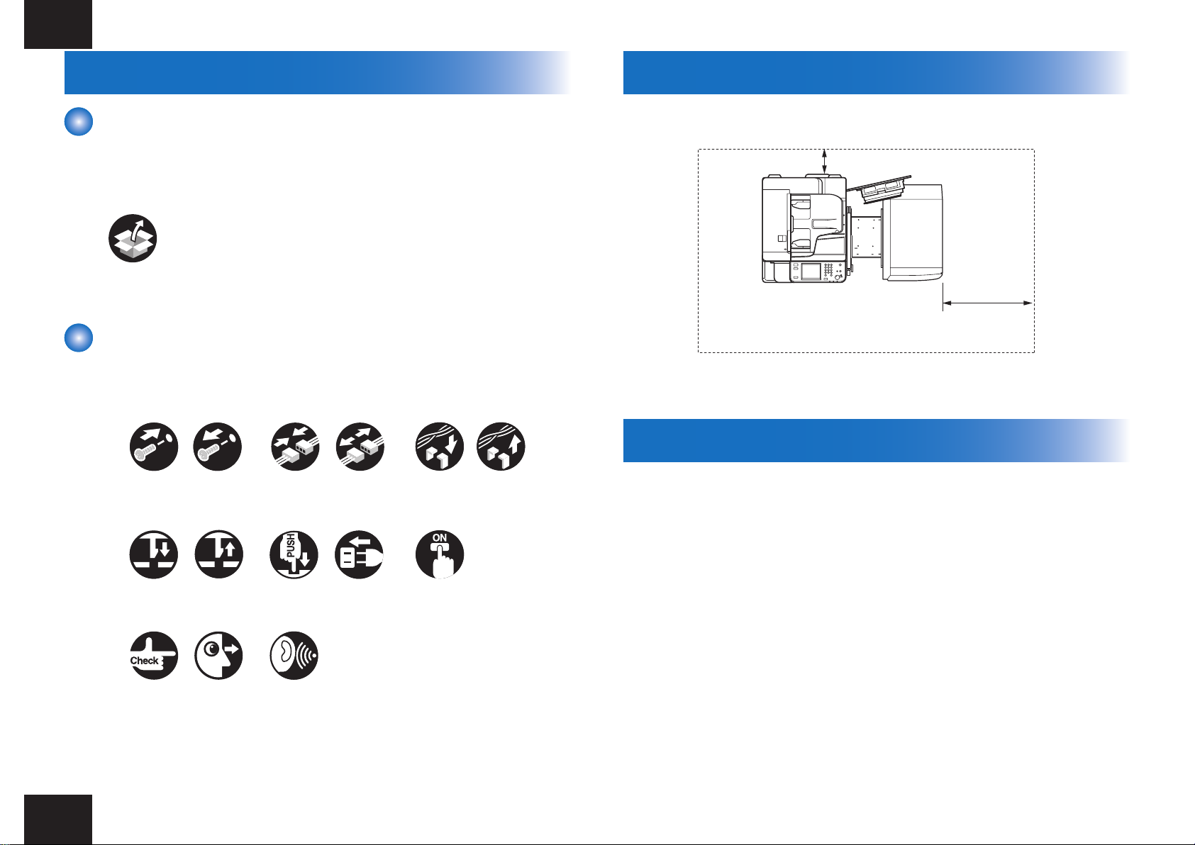
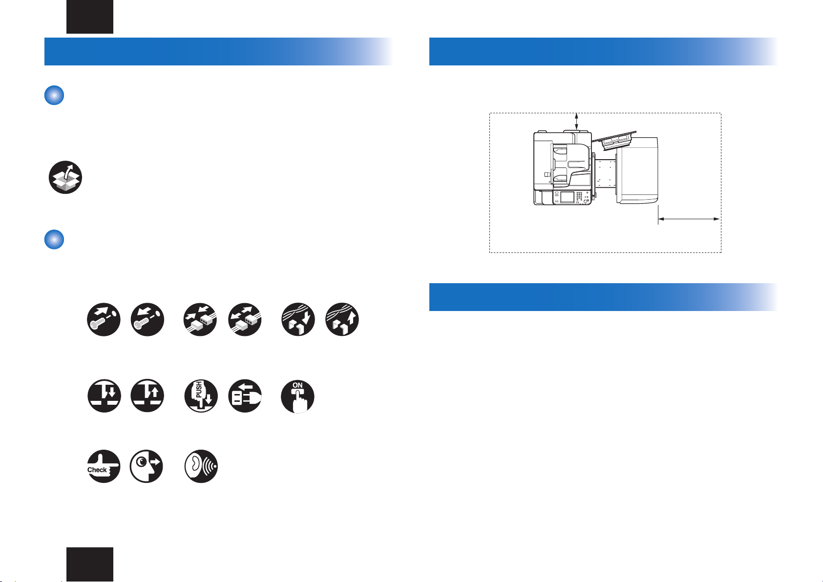
The frequently-performed operations are described with symbols in this procedure.
Screw
Claw
Tighten
Connector
Remove Connect
Disconnect
Harness
Secure Free
Checks to Make before Installation
The minimum space required for installation and maintenance is shown below.
100 mm or more
500 mm or more
F-1-2
Check items when Turning OFF the Main Power
1. The host machine and the pedestal have properly been installed.
2. Check that the main power switch is OFF.
1) Turn OFF the main power switch of the host machine.
2) Be sure that the control panel display and the main power lamp are both turned OFF,
and then disconnect the power plug.
Insert
Checking instruction
Check items when Turning OFF the Main Power
Remove
Push
Sound CheckCheck Visual Check
Plug in
Turn on
2
Checking the Supplied Parts
B
C
[5]
[14]
[10]
[17]
[1]
[3]
[4]
[7]
[6]
[2]
[5]
[8]
[5][9]
[18]
C
A
[5]
[13]
[5]
[5]
[15]
[16]
[12]
[13]
[11]
3
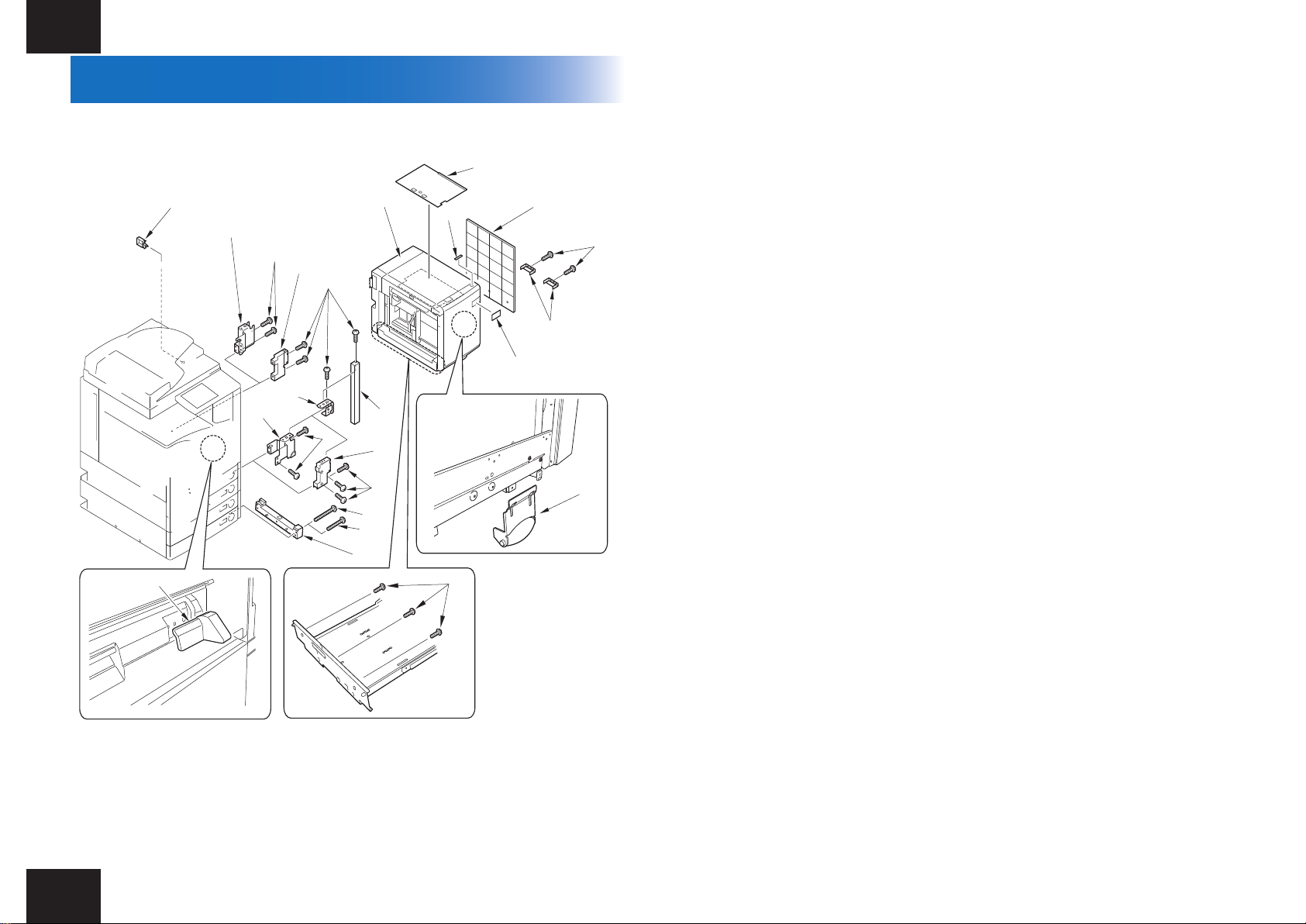
Checking the Supplied Parts
Open the container box and check that none of the included parts is missing.
□ [1] Paper deck 1unit
□ [2] Lifter plate sheet 1pc (*1)
□ [3] Open label 1pc
□ [4] Paper deck right cover 1pc
□ [5] Binding screw (M4x8) 12pcs (*2)
□ [6] Bottom stay cover 2pcs
□ [7] Paper size label 1pc
□ [8] Roller support plate 1pc
□ [9] Right cover guide 1pc
□ [10] Deck mounting stay 1pc
□ [11] Binding screw (M4x30)(Black) 5pcs (*3)
□ [12] Binding screw (M4x40)(Silver) 5pcs (*4)
□ [13] Latch catch C 2pcs (*4)
□ [14] Latch front cover 1pc
□ [15] Latch catch A 1pc (*3)
□ [16] Latch catch guide 1pc
□ [17] Latch catch B 1pc (*3)
□ [18] Harness guide 1pc
*1: A4 model only
*2: Use 12 pieces of the screws when this unit is equipped to iR ADVANCE C5051 series.
Use 11 pieces of the screws when this unit is equipped to iR ADVANCE 4045/4051 series.
*3: For iR ADVANCE 4045/4051 series
*4: For iR ADVANCE C5051 series
Checking the Supplied Parts
F-1-3
3
Unpacking Procedure
4
Unpacking Procedure
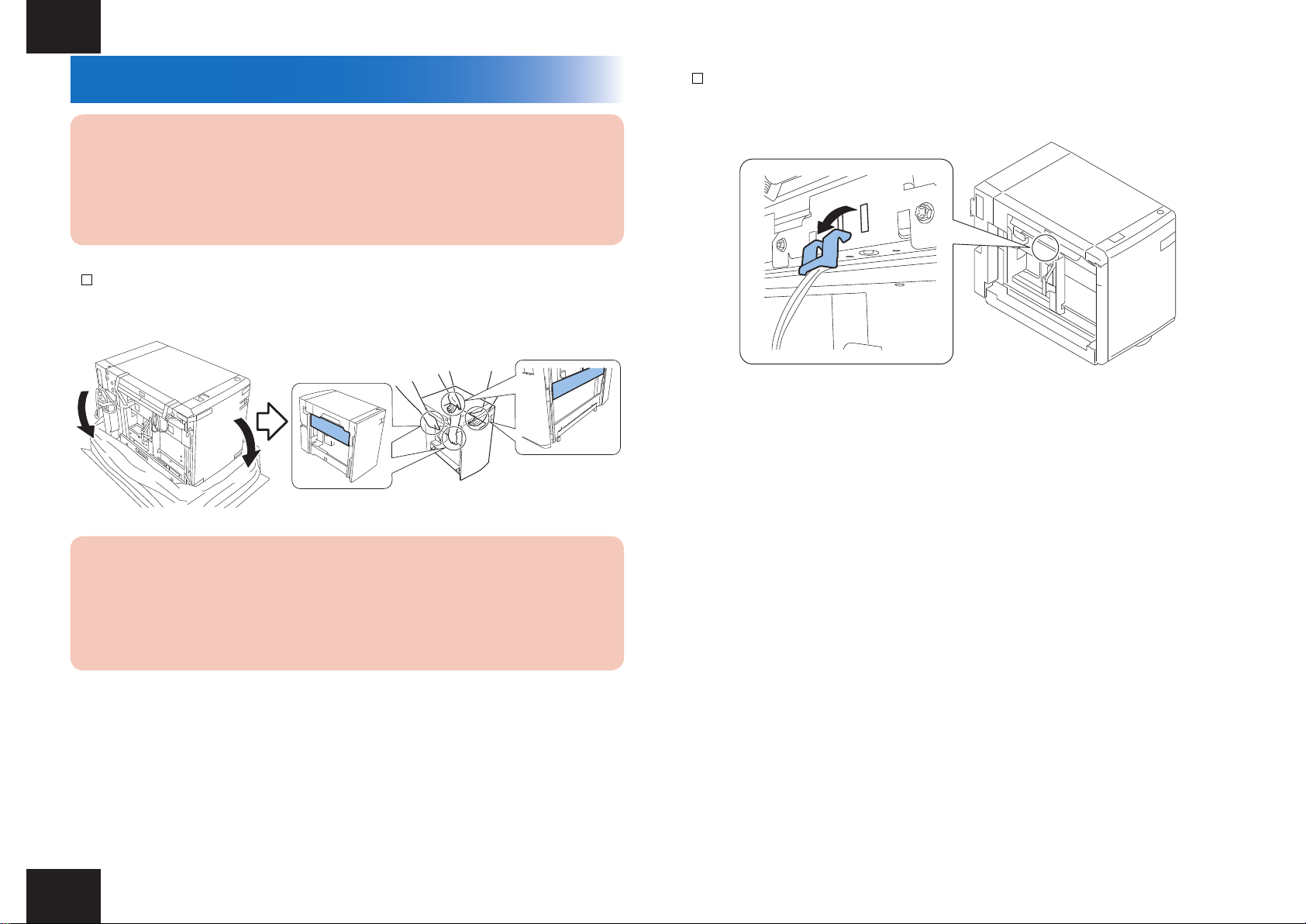
CAUTION:
The paper deck is secured with packaging tapes and cushioning materials to protect
it against vibration and shock during transportation. Remove all packaging tapes and
cushioning materials before installing the equipment. Save the removed cushioning
materials in case you need to use them again to transport the equipment for relocation
or repair.
1) Open the plastic packing bag of the paper deck and then take out the paper deck from the
palette.
F-1-4
2) Remove the roller pressure release part and package tape from the paper deck.
F-1-5
Caution:
When holding the paper deck at the installation, be ready with the two persons and
surely hold the right and left stays. Fail to do so may result in the deformation of the
paper deck.
(Weight: approximately 30 kg)
Unpacking Procedure
4
Installation procedure > Preparing the Host Machine > Preparing the Host Machine for iR ADVANCE 4045/4051 series
5
Installation procedure
Preparing the Host Machine
The preparation work depends on the connected host machine. Follow the procedure of each
host machine.
-When the paper deck is connected to iR ADVANCE 4045/4051 series: See P-5 to P-7.
-When the paper deck is connected to iR ADVANCE C5051 series: See P-8 to P-12.
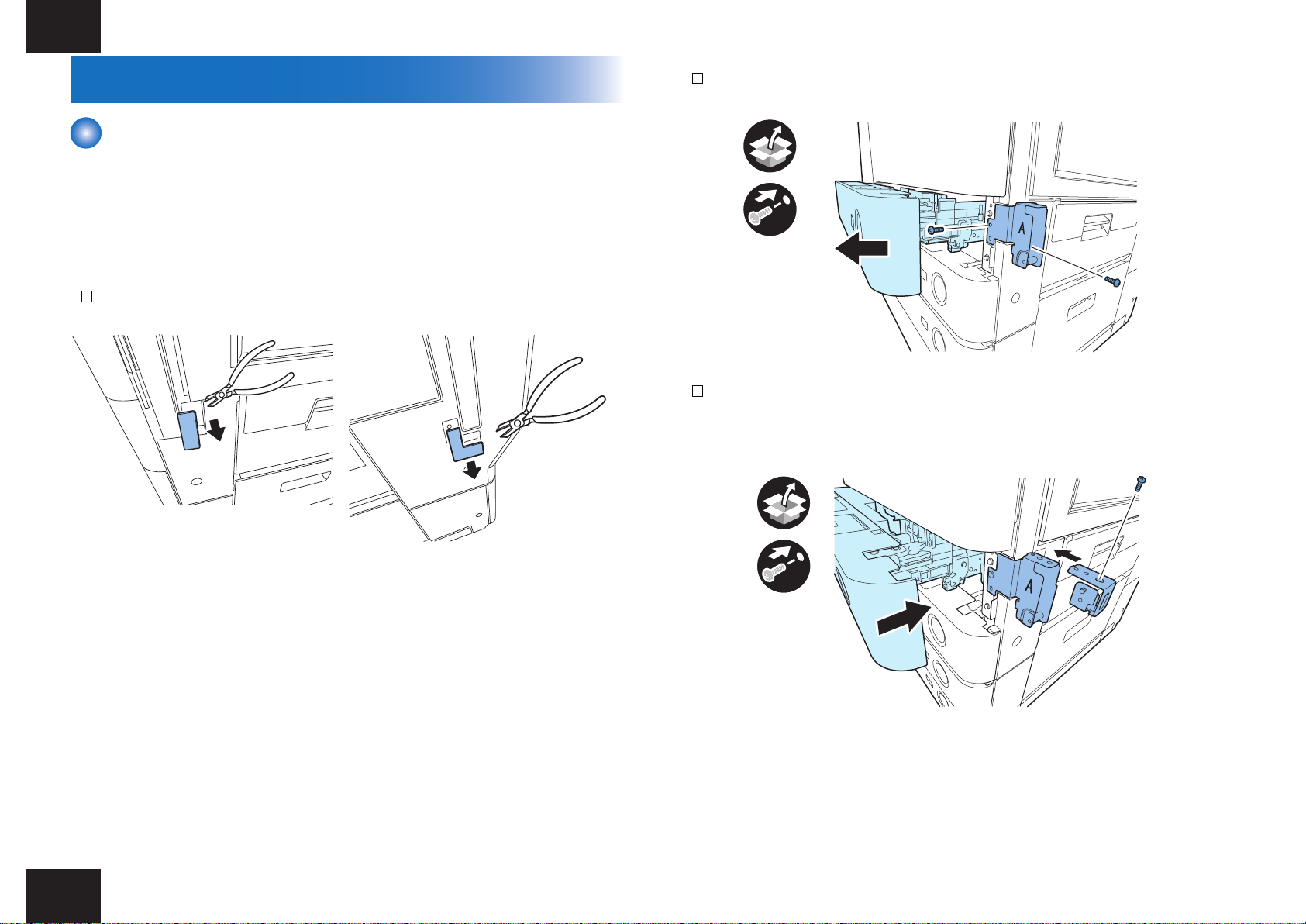
■Preparing the Host Machine for iR ADVANCE 4045/4051 series
1) Cut out the blindfold covers on the right side of the host machine using the nipper.
F-1-6
2) Draw out the upper cassette and install the latch catch A with the 2 binding screws (M4x8).
x2
3) Attach the latch catch guide to the latch catch A with the binding screws (M4x8). Then set
the upper cassette into the machine.
F-1-8
F-1-7
Installation procedure > Preparing the Host Machine > Preparing the Host Machine for iR ADVANCE 4045/4051 series
x1
F-1-9
5
Installation procedure > Preparing the Host Machine > Preparing the Host Machine for iR ADVANCE 4045/4051 series
x2
6
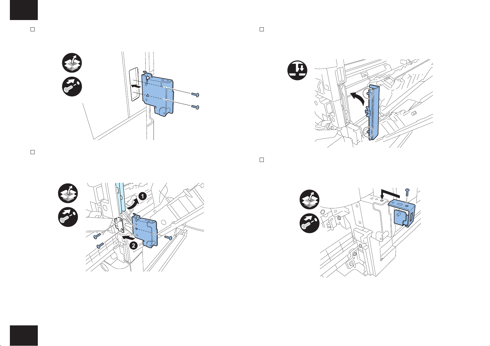
4) Install the latch catch B with the 2 binding screws (M4x8).
B
x2
F-1-10
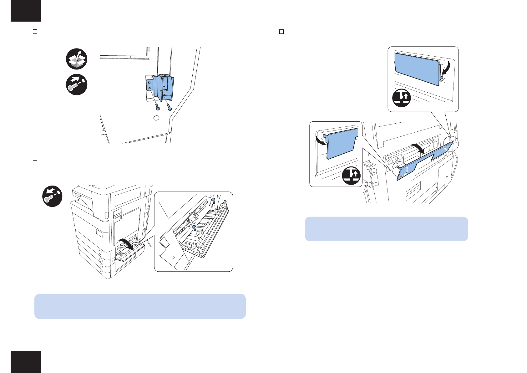
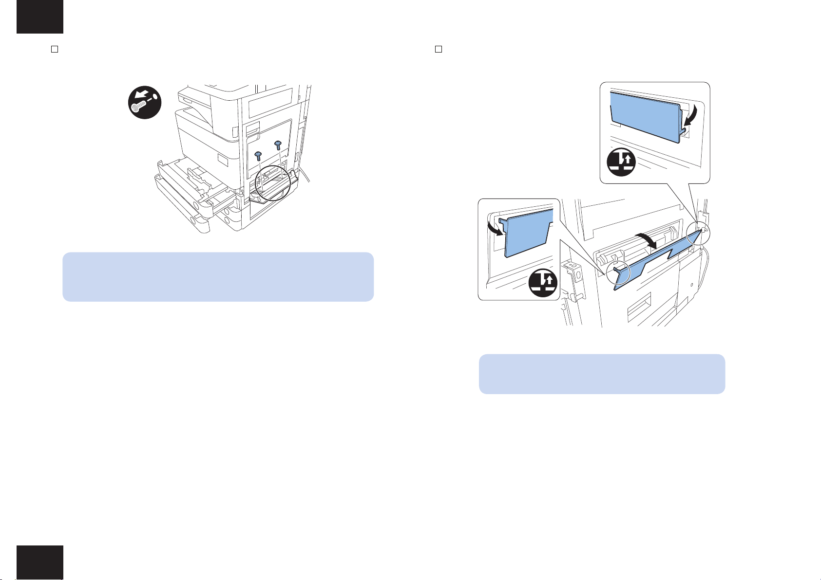
5) Open the right lower cover of the host machine and remove the 2 screws.
6) Close the right lower cover. Then remove the blindfold cover by releasing the 2 hooks.
F-1-12
F-1-11
NOTE:
The one of the removed screws is used in later.
Installation procedure > Preparing the Host Machine > Preparing the Host Machine for iR ADVANCE 4045/4051 series
NOTE:
The removed blindfold cover is no longer used.
6
Installation procedure > Preparing the Host Machine > Preparing the Host Machine for iR ADVANCE 4045/4051 series
7
7) Temporarily set the right lower cover guide to the position shown in the gure. Holding the
right lower cover guide, open the right lower cover again and release the stopper from the
shaft to open the right lower cover moreover. Then x the right lower cover guide with the
screw removed at step 5). After nishing the work, hook the stopper to the shaft and close
the right lower cover.
8) Install the deck mounting stay with the 5 binding screws (M4x30).
x5
F-1-14
NOTE:
The 5 binding screws (M4x40) are not used.
9) Attach the latch front cover with the binding screw (M4x8).
x1
F-1-13
NOTE:
When the host machine is equipping with the cassette pedestal, open the
cassette pedestal right cover before opening the right lower cover.
Installation procedure > Preparing the Host Machine > Preparing the Host Machine for iR ADVANCE 4045/4051 series
x1
x1
F-1-15
7
Installation procedure > Preparing the Host Machine > Preparing the Host Machine for iR ADVANCE C5051 series
x1
■Preparing the Host Machine for iR ADVANCE C5051 series
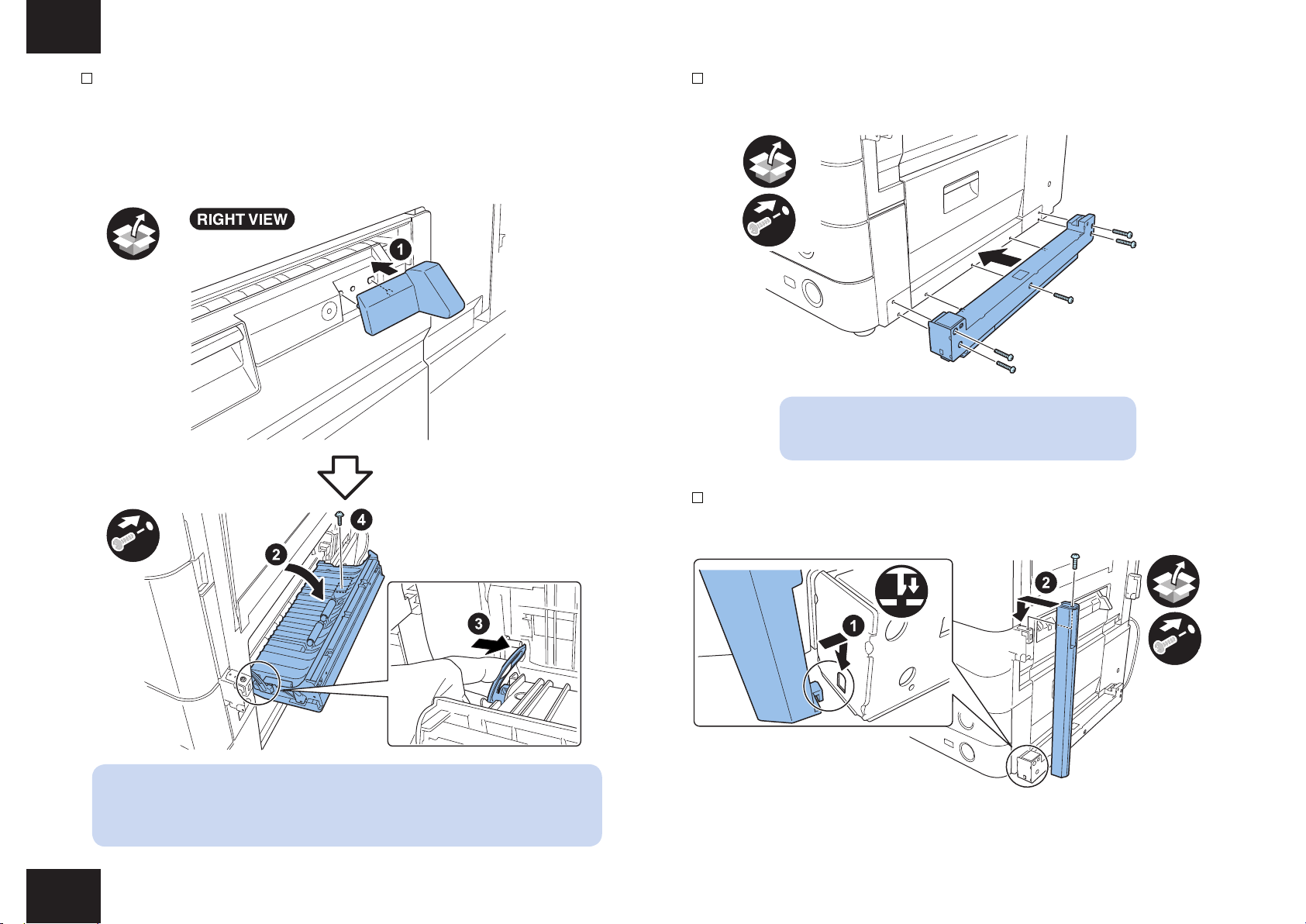
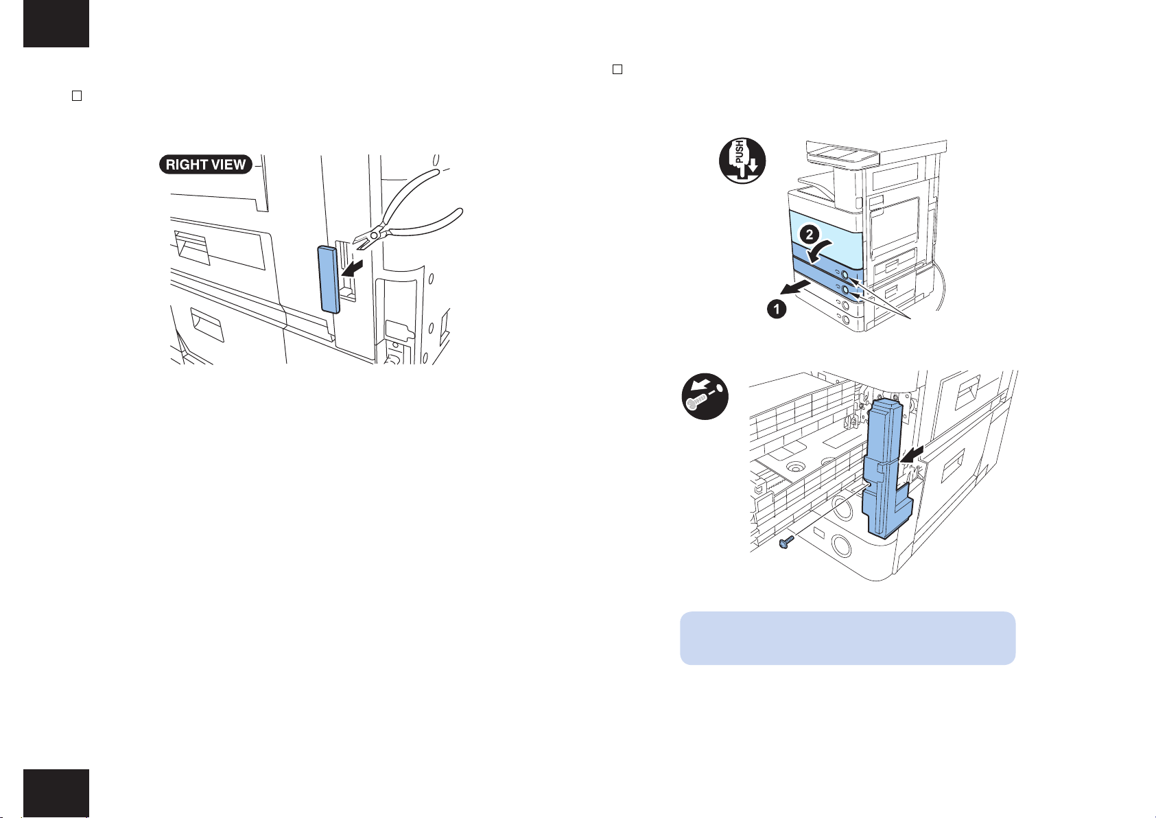
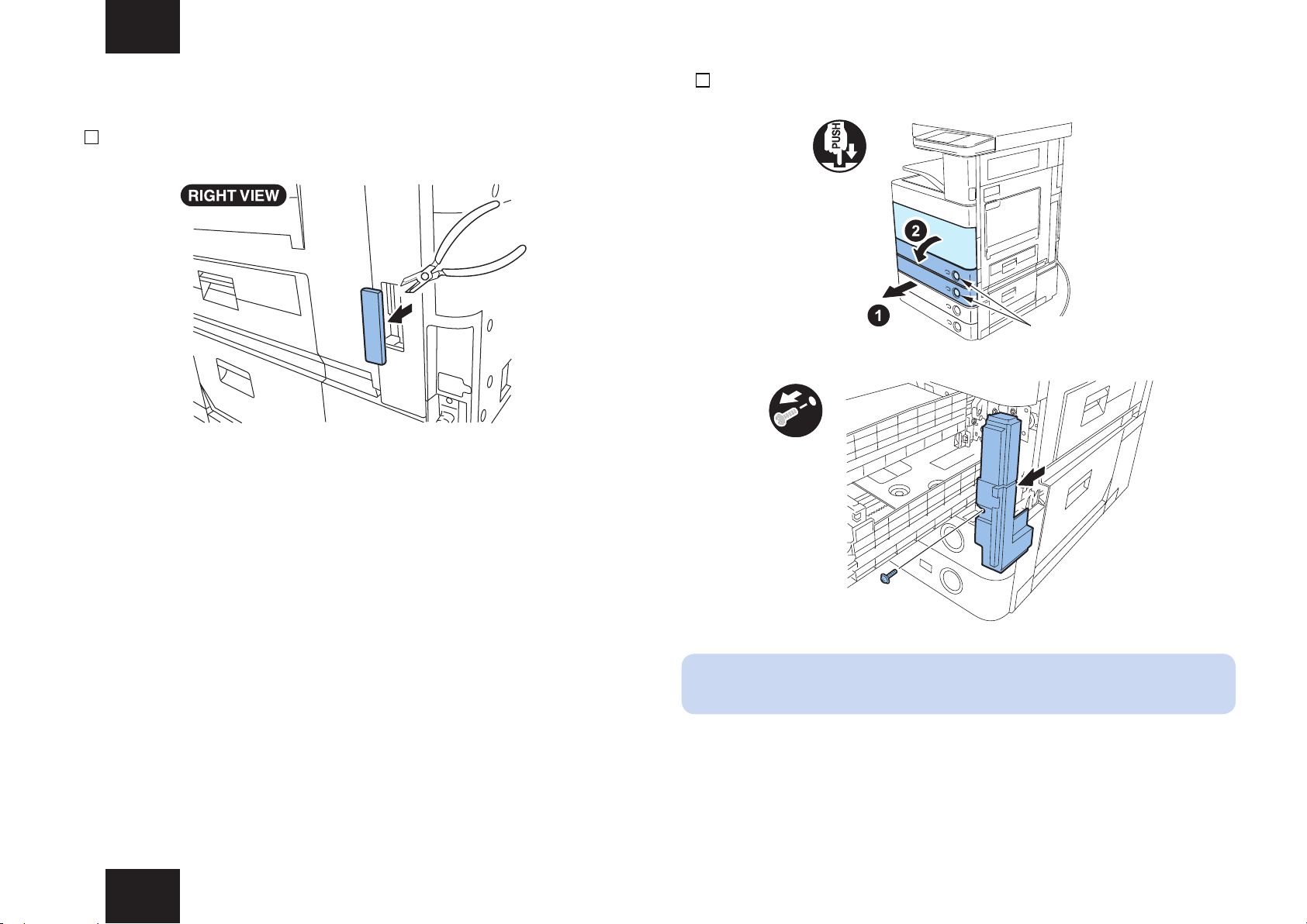
1) Cut out the blindfold cover on the right rear side of the host machine using the nipper.
F-1-16
8
2) Open the second and rst cassettes and the front cover, then remove the small right cover
by removing the screw.
x2
PUSH
F-1-17
Installation procedure > Preparing the Host Machine > Preparing the Host Machine for iR ADVANCE C5051 series
F-1-18
NOTE:
The removed screw is used later.
8
Installation procedure > Preparing the Host Machine > Preparing the Host Machine for iR ADVANCE C5051 series
9
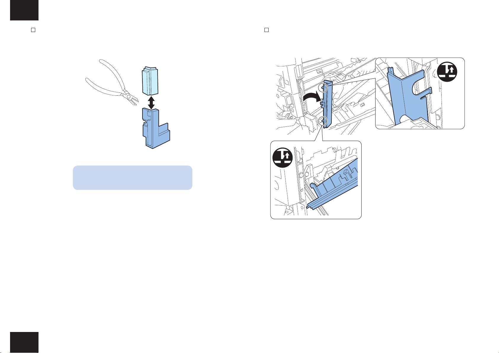
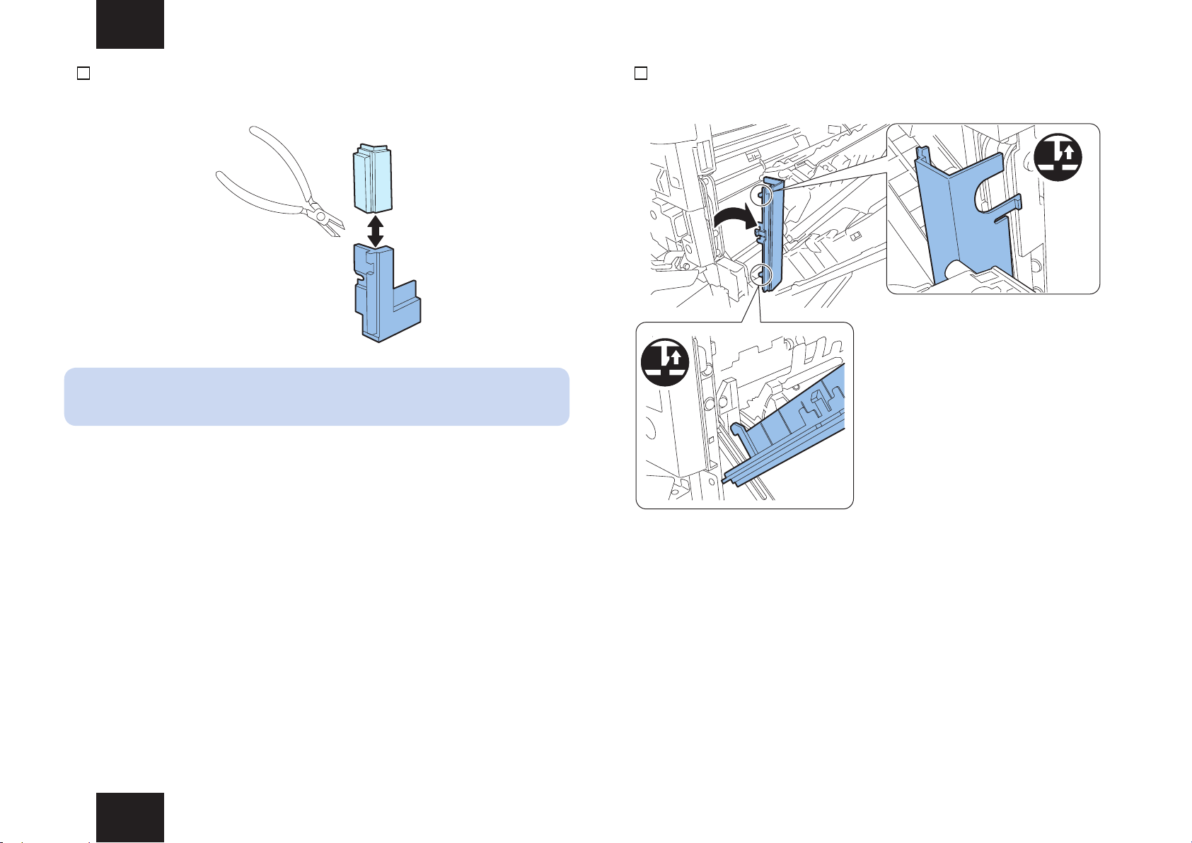
3) Cut out the upper part of the small right front cover using the nipper, and then reinstall the
lower part to the original position with the screw removed at step 2).
F-1-19
NOTE:
The removed upper part is no longer used.
4) Open the right door of the host machine and remove the handle cover (front side), and
then close the right door.
Installation procedure > Preparing the Host Machine > Preparing the Host Machine for iR ADVANCE C5051 series
F-1-20
9
Installation procedure > Preparing the Host Machine > Preparing the Host Machine for iR ADVANCE C5051 series
x2
10
5) Open the right lower cover to remove the 2 screws which are retaining the blindfold cover.
F-1-21
NOTE:
The one piece of the removed screws is used later.
6) Close the right lower cover. Then remove the blindfold cover by releasing the 2 hooks.
Installation procedure > Preparing the Host Machine > Preparing the Host Machine for iR ADVANCE C5051 series
NOTE:
The removed blindfold cover is no longer used.
10
Installation procedure > Preparing the Host Machine > Preparing the Host Machine for iR ADVANCE C5051 series
x3
11
7) Using the 2 binding screws (M4x8), install the latch catch C in the position where the
blindfold cover was removed at step 1).
x2
F-1-22
8) Pull up the handle as shown. Then using the 3 binding screws (M4x8), install the latch
catch C in the position where the upper part of the small right front cover was removed at
step 4).
9) Open the right door of the host machine and reinstall the handle cover (front side) removed
at step 4 to the original position. Then close all covers and set the cassettes into the
machine.
x2
F-1-24
10) Install the latch catch guide on the front side of latch catch C using the binding screw
(M4x8).
F-1-23
Installation procedure > Preparing the Host Machine > Preparing the Host Machine for iR ADVANCE C5051 series
x1
F-1-25
11
Installation procedure > Preparing the Host Machine > Preparing the Host Machine for iR ADVANCE C5051 series
12
11) Temporarily set the right lower cover guide to the position shown in the gure. Holding the
right lower cover guide, open the right lower cover again and release the stopper from the
shaft to open the right lower cover moreover. Then x the right lower cover guide with the
screw removed at step 5). After nishing the work, hook the stopper to the shaft and close
the right lower cover.
12) Install the supplied deck mounting stay with the 5 supplied binding screws (M4x40).
x5
F-1-27
NOTE:
The supplied 5 binding screws (M4x30) are not used.
13) Attach the supplied latch front cover with the supplied binding screw (M4x8).
x1
F-1-26
NOTE:
When the host machine is equipping with the cassette pedestal, open the cassette
pedestal right cover before opening the right lower cover.
Installation procedure > Preparing the Host Machine > Preparing the Host Machine for iR ADVANCE C5051 series
x1
x1
F-1-28
12
Installation procedure > Preparing the Host Machine > Connecting with the Host Machine and Preparing the Paper Deck
■Connecting with the Host Machine and Preparing the Paper
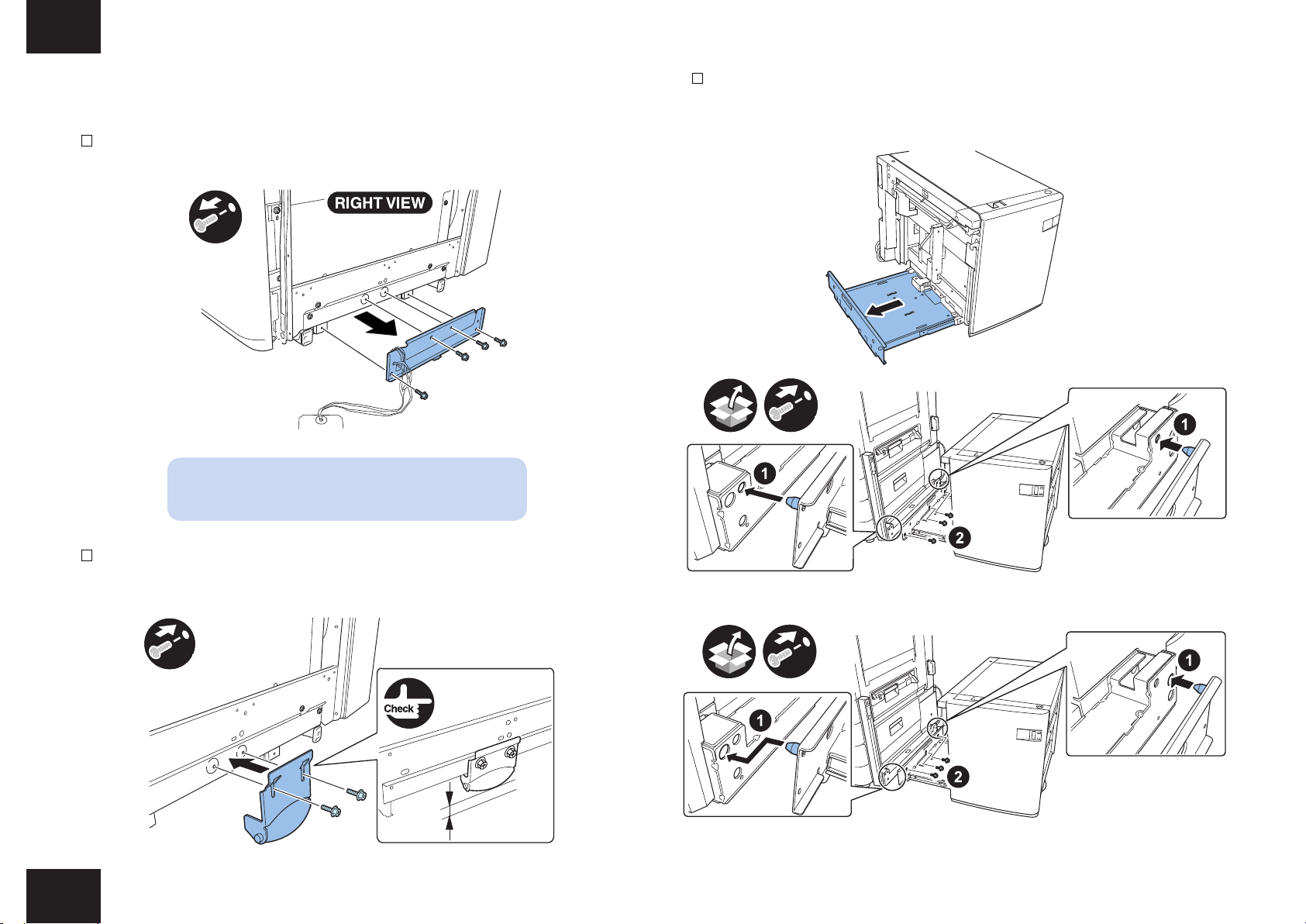
3) Draw the deck mounting cradle, insert the positioning pin to the hole of deck mounting stay
Deck
1) Remove the 4 screws to remove the bracket from the right side of paper deck.
x4
13
and then x the deck mounting cradle using the 3 binding screws (M4 x 8).
F-1-31
F-1-29
NOTE:
The two pieces of the removed screws are used later.
2) Install the roller support plate using the 2 screws removed at step 1) after positioning the
roller 3mm high from the oor.
x2
3㎜
F-1-30
Installation procedure > Preparing the Host Machine > Connecting with the Host Machine and Preparing the Paper Deck
x3
x3
iR ADVANCE 4045/4051 series
iR ADVANCE C5051 series
F-1-32
F-1-33
13

Installation procedure > Preparing the Host Machine > Connecting with the Host Machine and Preparing the Paper Deck
14
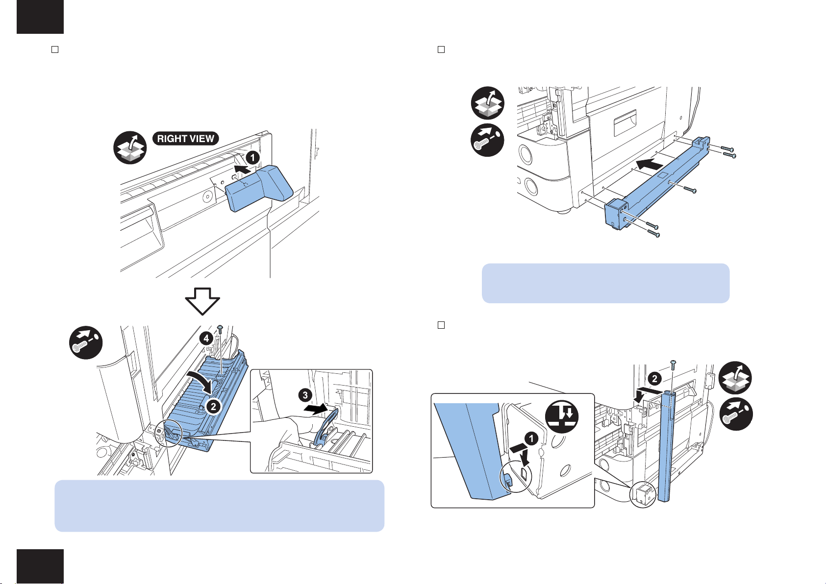
4) Remove the 2 screws and push down the release lever of paper deck compartment with
your nger to open the compartment.
x2
F-1-34
5) Remove the cushioning material from the compartment.
F-1-36
6) Loosen the 4 screws, and detach the deck front cover.
NOTE:
As a point reference to indicate the position of the deck front cover, be sure to mark the
appropriate graduation mark.
F-1-35
NOTE:
The removed screws are used later.
Installation procedure > Preparing the Host Machine > Connecting with the Host Machine and Preparing the Paper Deck
F-1-37
14

Installation procedure > Preparing the Host Machine > Connecting with the Host Machine and Preparing the Paper Deck
15
7) Push in the compartment, and then set the paper deck to the host machine.
8) Loosen the 4 screws retaining the roller support plate in the front side. Then tighten the
4 screws after positioning the roller support plate so that the clearance becomes 3 mm
between the roller and the oor.
3mm
F-1-38
9) Remove the paper deck from the host machine and then draw out the compartment.
10) Fit the deck front cover as if to match it against the coupling of the paper level indicator;
then tighten the screw while referring to the graduation you marked previously.
F-1-40
NOTE:
When attaching the deck front cover, turn the gear of the paper level
indicator fully counterclockwise so that the indicator is "white".
F-1-39
Installation procedure > Preparing the Host Machine > Connecting with the Host Machine and Preparing the Paper Deck
11) Set the paper deck to the host machine.
F-1-41
15

Installation procedure > Preparing the Host Machine > Connecting with the Host Machine and Preparing the Paper Deck
x2
x3
x2
16
12) Install the 2 bottom stay covers using the 2 binding screws (M4x8).
F-1-42
13) Install the paper deck right cover using the 3 screws removed at step 1) and step 4).
14) Close the compartment.
15) Remove the connector blindfold plate of the host machine.
iR ADVANCE 4045/4051 series
F-1-44
MEMO:
Hook claws of the upper part of paper deck right cover on the holes of paper deck main
unit stay and then install the paper deck right cover with the right edge inserted to the
inside of rear cover.
Installation procedure > Preparing the Host Machine > Connecting with the Host Machine and Preparing the Paper Deck
F-1-43
iR ADVANCE C5051 series
F-1-45
16
Installation procedure > Preparing the Host Machine > Connecting with the Host Machine and Preparing the Paper Deck
17
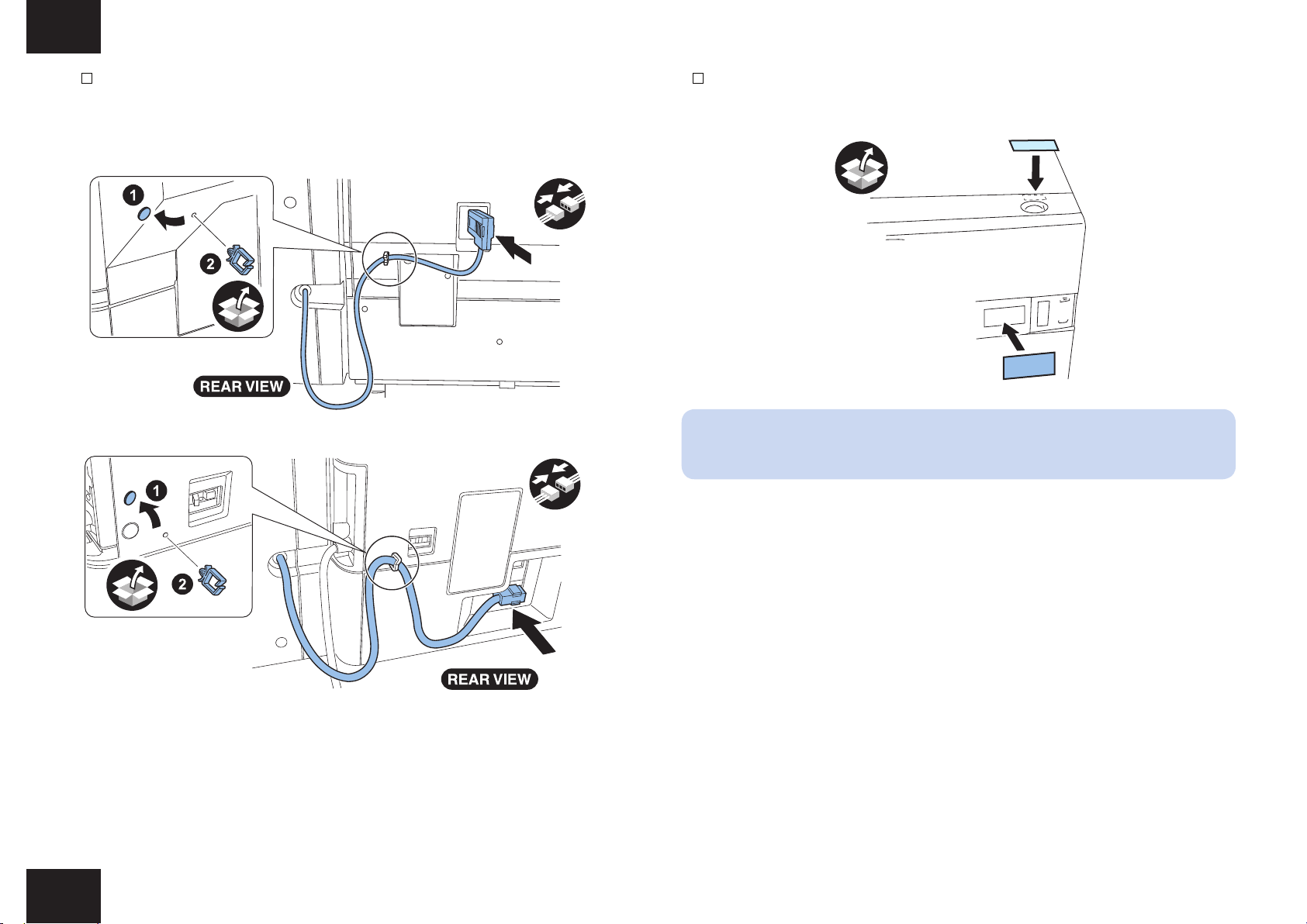
16) Remove the blindfold seal at the rear side of the host machine and attach the harness
guide to the place where the seal has been removed. Then clamp the cable as shown in
the gure.
x1
1
iR ADVANCE 4045/4051 series
F-1-46
x1
17) Find out the user's needs, and attach the paper size label and open label to the paper
deck.
F-1-48
NOTE:
Perform the following steps 18) and 19) when the deck paper size is A4.
iR ADVANCE C5051 series
Installation procedure > Preparing the Host Machine > Connecting with the Host Machine and Preparing the Paper Deck
F-1-47
17

Installation procedure > Preparing the Host Machine > Connecting with the Host Machine and Preparing the Paper Deck
18) When the host machine is turned on and the remaining paper indicator of this unit
changes to "black" (with lifter plate fully raised), press the release button of paper deck
compartment.
19) Remove the backing paper from the supplied lifter plate sheet, and then attach it to the
lifter plate.
F-1-49
18
A
B
F-1-50
NOTE:
When attaching the lifter plate sheet, attach the lifter plate sheet to the lifter plate while
butting the lifter plate sheet against sections A and B of the rear separation sheet. At
that time, check to see that the lifter plate sheet has not ridden over the front separation
sheet.
Installation procedure > Preparing the Host Machine > Connecting with the Host Machine and Preparing the Paper Deck
18

Changing the Paper Size
19
Changing the Paper Size
1) Open the compartment.
2) If the lifter of the paper deck is in up position, turn on the host machine and push down both
sensor levers (upper/lower) of the power supply position sensor inside the compartment
with your ngers so that the lifter will move to its lower limit.
F-1-51
3) Remove the screw, and mount the paper rear end guide plate to suit the new paper size.
4) In the same way, remove the screw (1pc.each), and adjust the position of the left/right
guide plates to suit the new paper size.
NOTE:
If the size is set to LTR, it is unnecessary to use the rear end guide plate.
To nd out the paper size, check the mark on the bottom plate.
5) In service mode, set the new paper size: LEVEL1/COPIER>OPTION>ACC>DK-P.
-When the host machine is iR ADVANCE 4045/4051 series:
0: A4, 2: LTR
-When the host machine is iR ADVANCE C5051 series:
0: A4, 1: LTR
NOTE:
After you have changed the paper size, be sure to turn off and then on the host
machine.
x3
Changing the Paper Size
19

Adjustment > Adjusting the Position of the Front Cover
20
Adjustment
Adjusting the Left Edge Margin
■For iR ADVANCE 4045/4051 series
1) Check to make sure that the 2 adjusters of the pedestal of the host machine are in contact
with the oor.
2) Turn on the host machine.
3) Check to see that the paper deck is used as the source of paper and the operation is
correct.
4) Make copies/prints of the test image, and check the output images to see that the left edge
margin of the paper deck is the standard: 2.5 +/- 1.5 mm. Otherwise, perform the following:
<Left Edge Margin Adjustment of Paper Deck>
4-1) Set the host machine to the service mode (LEVEL 2) and select “DK-ADJ-Y”.
LEVEL2/COPIER>ADJUST>MISC>DK-ADJ-Y
4-2) According to the test image, change the input value.
As the value is changed by 1, the left edge margin is increased or decreased by 0.1 mm.
+: Left margin becomes larger. (An image moves to the right.)
-: Left margin becomes smaller. (An image moves to the left.)
4-3) After the completion of the adjustment, exit the service mode.
As the value is changed by 1, the left edge margin is increased or decreased by 0.1 mm.
+: Left margin becomes larger. (An image moves to the right.)
-: Left margin becomes smaller. (An image moves to the left.)
4-3) After the completion of the adjustment, exit the service mode.
Adjusting the Position of the Front Cover
1) Be sure that the front cover is positioned so that the gap between the front cover and the
upper front cover is the standard: 3 +/- 1 mm. Otherwise, adjust the position of the front
cover with the 4 screws tightening the front cover.
■For iR ADVANCE 5051 series
1) Check to make sure that the 2 adjusters of the pedestal of the host machine are in contact
with the oor.
2) Turn on the host machine.
3) Check to see that the paper deck is used as the source of paper and the operation is
correct.
4) Make copies/prints of the test image, and check the output images to see that the left edge
margin of the paper deck is the standard: 2.5 +/- 1.5 mm. Otherwise, perform the following:
<Left Edge Margin Adjustment of Paper Deck>
4-1) Set the host machine to the service mode and select “ADJ-DK”.
LEVEL1/COPIER>ADJUST>FEED-ADJ>ADJ-DK
4-2) According to the test image, change the input value.
Adjustment > Adjusting the Position of the Front Cover
3±1mm
F-1-52
20
21
本設置手順書の見方について
同梱部品を使用する場合
本製品に同梱されている部品を使用する場合は、 イラスト内に同梱部品使用のシンボルを記
載してある。
同梱部品
イラスト内のシンボルマークについて
本手順書では、 よく行う動作などについてシンボルマークで表現している。
ビス
爪
取付け
コネクタ
取外し 取外し
取付け
束線
取外し取付け
設置環境の確認
以下に設置および保守作業に必要なスペースを記す。
100 mm以上
500 mm以上
F-1-1
本体主電源 OFF の確認
1. 本体、 ペディスタルの設置が完了してから本機を取付けること。
2. 本機の電源が OFF であることを確認する。
1) 本体の主電源スイッチを OFF する。
2) 操作パネルの表示と主電源ランプが消えたことを確認してから電源プラグを外す。
取付け
取外し
音確認確認 目視
押す
コンセント
差込み
スイッチON
21

B
C
[5]
[14]
[10]
[17]
[1]
[3]
[4]
[7]
[6]
[2]
[5]
[8]
[5][9]
[18]
C
A
[5]
[13]
[5]
[5]
[15]
[16]
[12]
[13]
[11]
22
同梱部品の確認
梱包箱を開けて、 同梱品がすべて揃っていることを確認する。
□ [1] ペーパーデッキ本体 1 個
□ [2] リフター板シート 1 個 (*1)
□ [3] オープンラベル 1 個
□ [4] ペーパーデッキ右カバー 1 個
□ [5] バインドビス (M4x8) 12 本 (*2)
□ [6] 底ステーカバー 2 個
□ [7] 用紙サイズラベル 1 個
□ [8] コロ支板 1 個
□ [9] 右下カバーガイド 1 個
□ [10] デッキ取付けステー 1 個
□ [11] バインドビス (M4x30) (黒) 5 本 (*3)
□ [12] バインドビス (M4x40) (銀) 5 本 (*4)
□ [13] ラッチ受け C 2 個 (*4)
□ [14] ラッチ前カバー 1 個
□ [15] ラッチ受け A 1 個 (*3)
□ [16] ラッチ受けガイド 1 個
□ [17] ラッチ受け B 1 個 (*3)
□ [18] 束線ガイド 1 個
*1 : A4 モデルのみ
*2 : iR ADVANCE C5051 シリーズに接続する場合は、 12 本使用する。
iR ADVANCE 4045 シリーズに接続する場合は、 11 本使用する。
*3 : iR ADVANCE 4045 シリーズ用
*4 : iR ADVZNCE C5051 シリーズ用
F-1-2
22

23
開梱手順
注意 :
輸送時の振動や衝撃から装置を保護するため、 固定テープ、 緩衝材などで固定されて
出荷されている。 手順に従って、 すべての固定テープ、 緩衝材を取り外してから設置
を行うこと。 なお、 取外した緩衝材は、 ペーパーデッキを移設や修理などで輸送する際
に利用する為、 保管しておくこと。
1) ペーパーデッキを梱包している袋を開け、 ペーパーデッキをパレットから降ろす。
2) ペーパーデッキから、 ローラー圧解除コマと梱包テープを外す。
F-1-4
F-1-3
注意 :
設置時にペーパーデッキを持ち上げる際は、 2 人以上で必ず左右のステーを持つこと。
他の部分を持つと変形の原因になる。 (本体重量 : 約 30Kg)
23

24
設置手順
接続機器側の取付け準備
接続機器によって準備作業が異なる。 それぞれの機器に応じた手順に従うこと。
・ iR ADVANCE 4045 シリーズと接続する場合 : P-24 ~ P-26
・ iR ADVANCE C5051 シリーズと接続する場合 : P-27 ~ P-31
■ 取付け準備 (iR ADVANCE 4045 シリーズに接続する場合)
1) 本体右側の目隠しカバーをニッパーで切取る。
2) 上段カセットを引出し、 ラッチ受け A をバインドビス 2 本 (M4 x 8) で取付ける。
x2
3) ラッチ受け A にラッチ受けガイドをバインドビス 1 本 (M4 x 8) で取付ける。 引き出した上
段カセットを戻す。
F-1-7
F-1-5
F-1-6
x1
F-1-8
24

25
4) ラッチ受け B をバインドビス 2 本 (M4 x 8) で取付ける。
B
x2
F-1-9
5) 本体の右下カバーを開け、 目隠しカバーを固定しているビス 2 本を外す。
x2
6) 右下カバーを閉める。 目隠しカバーのフックを解除して目隠しカバーを外す。
F-1-11
メモ :
外したビスの内 1 本は後の手順で使用する。
メモ :
外した目隠しカバーは使用しない。
F-1-10
25

26
7) 右カバーガイドを右下カバーの図の場所にセットする。 右カバーガイドを押えながら、 再度
右下カバーを開けてストッパを固定軸から解除して更に右下カバーを開き、 手順 5) で外し
たビス 1 本で右カバーガイドを固定する。 作業終了後、 ストッパを固定軸に戻して右下カ
バーを閉める。
x1
8) デッキ取付けステーをバインドビス (M4x30) 5 本で取付ける。
x5
F-1-13
メモ :
バインドビス (M4x40) 5 本は使用しない。
9) ラッチ前カバーをバインドビス (M4x8) で取付ける。
メモ :
カセットペディスタルが装備されている場合は、 右下カバーを開ける前に、 カセットペディスタ
ルの右カバーを開けること。
x1
x1
F-1-12
F-1-14
26
27
■ 取付け準備(iR ADVANCE C5051 シリーズに接続する場合)
1) 本体右後側の目隠しカバーをニッパで切取る。
F-1-15
2) 本体カセット 2 段目、 1 段目および前カバーを開け、 ビス 1 本で右側小カバーを外す。
x2
カセット
解除ボタン
F-1-16
x1
F-1-17
メモ :
外したビスは後で使用する。
27
28
3) 右前小カバーの上部をニッパーで切取り、 手順 2) で外したビスを使って下部を元の位置
に取付ける。
F-1-18
メモ :
切り取った上部は使用しない。
4) 本体の右扉を開けて、 取っ手カバー (前側) を外す。 その後、 右扉を閉める。
F-1-19
28

29
5) 右下カバーを開け、 目隠しカバーを固定しているビス 2 本を外す。 (内側 2 箇所)
x2
F-1-20
メモ :
外したビスのうち 1 本は後の手順で使用する。
6) 右下カバーを閉める。 本体右下扉部の目隠しカバーのフックを解除し外す。
F-1-21
メモ :
外した目隠しカバーは使用しない。
29

30
7) 手順 1) で外した目隠しカバーの部分に、 ラッチ受け C をバインドビス 2 本 (M4x8) で取
付ける。
x2
F-1-22
8) 取っ手を引上げて、 手順 2) で切取った右前小カバー上部の位置に、 バインドビス 3 本
(M4x8) で同梱のラッチ受け C を取付ける。
9) 本体右扉を開け、 手順 4) で外した本体の取っ手カバー (前側) を元の位置に取付ける。
開いているカバー類を全て閉め、 カセットを機内にセットする。
x2
F-1-23
10) ラッチ受け前側に同梱のバインドビス 1 本 (M4x8) で、 ラッチ受けガイドを取付ける。
x1
x3
F-1-24
30

31
11) 右カバーガイドを右下カバーの図の場所にセットする。 右カバーガイドを押えながら、 再
度右下カバーを開けてストッパを固定軸から解除して更に右下カバーを開き、 手順 5) で
外したビス 1 本で右カバーガイドを固定する。 作業終了後、 ストッパを固定軸に戻して右
下カバーを閉める。
x1
12) デッキ取付けステーをバインドビス 5 本 (M4x40) で取付ける。
x5
F-1-26
メモ :
バインドビス (M4x30) 5 本は使用しない。
13) ラッチ前カバーをバインドビス 1 本 (M4x8) で取付ける。
F-1-25
メモ :
カセットペディスタルが装備されている場合は、 右下カバーを開ける前に、 カセットペディスタル
の右カバーを開けること。
x1
x1
F-1-27
31

32
■ 接続機器との接続およびデッキの準備
1) ビス 4 本を外し、 ペーパーデッキ本体右側から固定金具を外す。
x4
メモ :
外したビスは、 後の手順で使用する。
3) デッキ取付け台を引出し、 位置決めピン部をデッキ取付けステーの穴に押し込み、 バイン
ドビス (M4x8) 3 本でデッキ取付け台を固定する。
F-1-30
F-1-28
x3
2) 手順 1) で外したビスのうち 2 本を使用し、 コロ支板をコロが床面から 3mm の位置になる
ように調整して取付ける。
x2
3㎜
F-1-29
x3
iR ADVANCE 4045 シリーズ
iR ADVANCE C5051 シリーズ
F-1-31
F-1-32
32

33
4) ビス 2 本を外し、 ペーパーデッキ収納庫の解除レバーを指で押し下げ、 収納庫を開く。
x2
F-1-33
5) 庫内の緩衝材を取出す。
F-1-35
6) ビス 4 本を緩めて、 デッキ前カバーを外す。
メモ :
デッキ前カバー取付け位置の目盛りに印をつけておくこと。
メモ :
外したビスは、 後の手順で使用する。
F-1-34
F-1-36
33

34
7) 収納庫を押し込んだ後、 ペーパーデッキを本体にセットする。
8) 本機正面のコロ支板のビス 4 本を緩め、 コロが床面から 3mm の位置になるように調整し
て取付ける。
3mm
F-1-37
9) ペーパーデッキを本体から解除し、 収納庫を引出す。
10) ペーパーデッキ前カバーを用紙残量表示のカップリングに
順 6) で付けておいた印に合わせて、 緩めたビスを締める。
メモ :
デッキ前カバーを取付ける前に残量表示部ギアを反時計方向に回し、 表示部が “白” になって
いることを確認する。
合わせるようにしてはめ込み、 手
F-1-39
F-1-40
F-1-38
11) ペーパーデッキをを本体にセットする。
34

35
12) バインドビス 2 本 (M4x8) で、 底ステーカバー 2 個を取付ける。
x2
F-1-41
13) 手順 1) と手順 4) で外したビスのうち 3 本で、 ペーパーデッキ右カバーを取付ける。
14) 収納庫を閉める。
15) 本体後側のコネクタ目隠し板を外す。
iR ADVANCE 4045 シリーズ
F-1-43
x2
x3
F-1-42
メモ :
ペーパーデッキ右カバー上部の爪をペーパーデッキ本体ステーの穴に、 右端を後ろカバーの
内側に入れて取付けること
iR ADVANCE C5051 シリーズ
F-1-44
35

36
16) 本体後面の目隠しシールをはがし、 その位置に束線ガイドを取付け、 図のようにケーブ
ルを固定する。
x1
iR ADVANCE 4045 シリーズ
F-1-45
x1
17) ユーザーの希望を確認し、 用紙サイズラベル、 およびオープンラベルをペーパーデッキ
に貼る。
F-1-47
メモ :
以下の手順 (18)、 (19) は、 デッキ用紙サイズが A4 の場合に行う。
iR ADVANCE C5051 シリーズ
F-1-46
36

18) 本体の電源を入れ、 本体の紙残量表示が” 黒” になったら (リフタ板が完全に上昇した
状態)、 ペーパーデッキ収納庫解除ボタンを押す。
19) 同梱のリフタ板シートから剥離紙をはがし、 図のようにリフタ板に貼る。
F-1-48
37
A
B
F-1-49
メモ :
リフタ板シート貼付け時は、 奥側分離シートの A 部と B 部にリフタ板シートを突き当てた状態で
貼る。 その時、 リフタ板シートが手前側分離シートに乗り上げていないことを確認する。
37

38
用紙サイズの切り替え
1) 収納庫を開く。
2) ペーパーデッキのリフタが上がっている場合は、 収納庫内の用紙補給位置センサのセン
サレバー (上 ・ 下) を同時に指で押し、 リフタを下限まで下げる。
F-1-50
3) ビス 1 本を外し、 用紙後端規制板の取付け位置を新しい用紙サイズに合わせて取付ける。
4) 同様にビス各 1 本を外し、 左右規制板の取付け位置を新しい用紙サイズに合わせる。
5) 本体のサービスモード (LEVEL1/COPIER > OPTION > ACC > DK-P) を用紙サイズに合
わせて設定する。
・ iR ADVANCE 4045 シリーズの時 :
0: A4、 2: LTR
・ iR ADVANCE C5051 シリーズの時 :
0: A4、 1: LTR
メモ :
設定変更後は必ず本体の電源を OFF/ON すること。
x3
メモ :
LTR サイズでは後端規制板を使用しない。 また、 用紙サイズは底板に刻印されている。
F-1-51
38

39
調整
左端余白調整
■ iR ADVANCE 4045 シリーズの場合
1) 本体のアジャスタ 2 個が着地していることを確認する。
2) 本体の電源スイッチを ON する。
3) ペーパーデッキから給紙を行い、 動作に問題が無いことを確認する。
4) テスト画像をコピー / プリントし、 画像の左端余白が規格 : 2.5±1.5mm 以内であることを
確認する。 規格から外れている場合は、 以下の手順に従いサービスモードで左端余白調
整を行う。
< ペーパーデッキ左端余白調整 >
4-1) サービスモード (レベル 2) に入り、” DK-ADJ-Y” を選択する。
LEVEL2/COPIER>ADJUST>MISC>DK-ADJ-Y
4-2) テスト画像の結果に応じて入力値を変える。
入力値 1 ごとに、 左端余白が 0.1mm ずつ増減する。
+ : 左端余白が広がる (画像が右に移動する)
- : 左端余白が狭まる (画像が右に移動する)
4-3) 調整が終了したら、 サービスモードから抜ける。
入力値 1 ごとに、 左端余白が 0.1mm ずつ増減する。
+ : 左端余白が広がる (画像が右に移動する)
- : 左端余白が狭まる (画像が左に移動する)
4-3) 調整が終了したら、 サービスモードから抜ける。
前カバーの取付け位置調整
1) 前カバーと前上カバーの隙間が規格 : 3±1mm であることを確認する。 規格から外れてい
る場合は、 前カバーの固定ビス 4 本で、 前カバー取付け位置を調整する。
3±1mm
■ iR ADVANCE C5051 シリーズの場合
1) 本体のアジャスタ 2 個が着地していることを確認する。
2) 本体の電源スイッチを ON する。
3) ペーパーデッキから給紙を行い、 動作に問題が無いことを確認する。
4) テスト画像をコピー / プリントし、 画像の左端余白が規格 : 2.5±1.5mm 以内であることを
確認する。 規格から外れている場合は、 以下の手順に従いサービスモードで左端余白調
整を行う。
< ペーパーデッキ左端余白調整 >
4-1) サービスモードに入り、” ADJ-DK” を選択する。
LEVEL1/COPIER>ADJUST>FEED-ADJ>ADJ-DK
4-2) テスト画像の結果に応じて入力値を変える。
F-1-52
39
 Loading...