

Page 1

CXDI Image Processing Software
MLT (S)
User’s Manual
Before using the instrument, be sure to read this manual thoroughly.
Also, read the manuals of other instruments in this system.
Keep the manual where it is easily accessible.
Page 2

Please Note
1. In no event will Canon be liable for direct or indirect consequential damage arising out of the use of this
product. Canon will not be liable for loss of image data due to any reason.
2. Please have this product installed by Canon representative or distributor.
3. Canon reserves the right to change the specifications of the product without prior notice.
© CANON INC. 2009
All rights reserved.
Under copyright laws, this manual may not be copied, in whole or in part, without the written consent of
Canon.
Page 3

Contents
1. Overview .....................................................................................................1
1.1 About MLT (S) ........................................................................................................... 1
1.2 Available Functions of MLT (S) ................................................................................. 2
2. Edit Exposure Mode Settings ......................................................................3
2.1 Procedures to Set Exposure Mode ........................................................................... 3
2.2 Setting Enhancement ................................................................................................ 7
2.3 Setting Noise Reduction ............................................................................................ 8
2.4 Setting Dynamic Range Adjustment ......................................................................... 9
2.4.1 Setting high-density sections ............................................................................. 9
2.4.2 Setting low-density sections ............................................................................. 10
3. QA Mode Settings .....................................................................................11
3.1 Procedures to Change Parameters ......................................................................... 11
3.2 Changing Enhancement .......................................................................................... 14
3.3 Changing Noise Reduction .....................................................................................15
3.4 Changing Dynamic Range Adjustment ................................................................... 16
3.4.1 Changing high-density sections ....................................................................... 16
3.4.2 Changing low-density sections ........................................................................ 17
4. QA Parameters .........................................................................................18
Page 4

Page 5

Notation Conventions
Notation 1
In this manual, the name of button is enclosed with a pair of brackets [ ], and the buttons that are selected in succession
are connected with > to indicate the order.
Example: On the Exposure screen, touch the followings:
[SYSTEM] > [EDIT EXPOSURE MODE]
Notation 2
If any detailed explanation for the operation or setting is available on other page in this manual, the page to refer is indicated with (→ page number).
Example: Please set the parameters by referring to 2.2 Setting Enhancement (→ P. 7 ) .
Notation 3
When description of the procedure or setting continues from an odd-numbered page (right page) to the subsequent evennumbered page (left page), a small note, [Continued on the following page »] appears at the bottom-right of the oddnumbered page to draw your attention.
Page 6

Page 7
1. Overview
1.1 About MLT (S)
NOTE: This user’s manual is for version 7.1 and later of the CXDI System Software.
The CXDI Image Processing Software MLT (S) (called “MLT (S)” in this manual) is
designed to extend the image processing functions provided with the CXDI series of Canon digital radiography system (called “CXDI” in this manual).
By installing MLT (S) on the Control PC, the advanced image processing features of MLT (S)
are brought into full scope both in the Edit Exposure Mode and QA Mode.
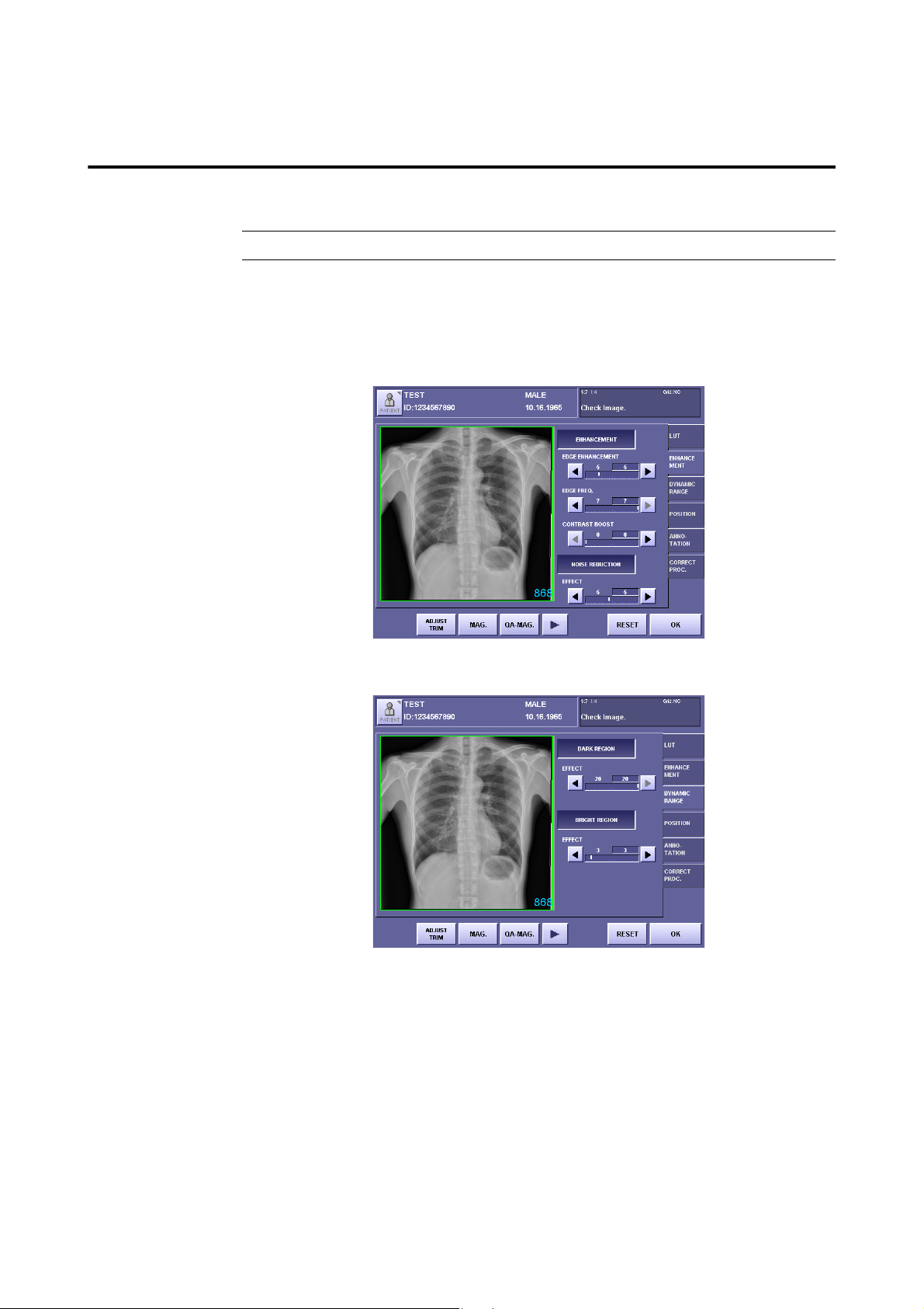
QA Mode Screen Extended by MLT (S) (ENHANCEMENT Tab)
QA Mode Screen Extended by MLT (S) (DYNAMIC RANGE Tab)
– 1 –
Page 8

1.Overview
1.2 Available Functions of MLT (S)
This manual describes the operating procedures of the following image processing function that
is available with MLT (S). For details and information on other image processing functions,
please refer to Operation Manual and Setup Guide.
Enhancement
This accentuates edge details and local contrast of the exposure image for improving
sharpness.
The degree of enhancement can be adjusted by setting the edge enhancement parameters.
The frequency band for edge enhancement can also be modified by setting the edge
frequency parameters.
The degree of enhancement of the local contrast can be adjusted by setting the contrast
boost parameters.
Noise Reduction
This reduces noise in the exposure image for improving granularity.
The EFFECT parameter setting can be used to adjust the degree of noise reduction.
Dynamic Range Adjustment
This improves the detectability of high-density and low-density areas in the exposure
image.
The settings for the maximum density parameter and minimum density parameters can
be used to adjust the dynamic range.
NOTE: The effects resulting from changes to the parameters may be difficult to check
in the exposure image of the QA mode screen.
In these cases, check by touching [MAG.] or [QA-MAG.] to display the
enlarged screen.
– 2 –
Page 9
Continued on the following page >>
2. Edit Exposure Mode Settings
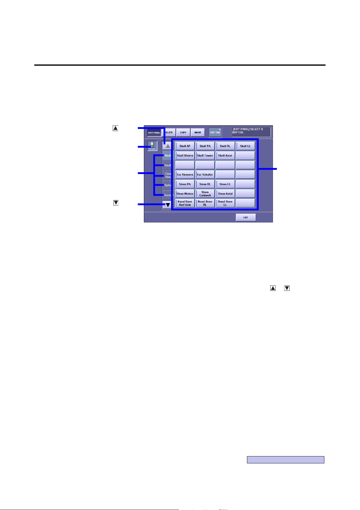
Sensor Unit
Button
Button
Button
Category Tab
Exposure Mode
2.1 Procedures to Set Exposure Mode
Display the Edit Exposure Mode screen
1
On the Exposure screen, touch the followings:
[SYSTEM] > [EDIT EXPOSURE MODE]
Edit Exposure Mode Screen
Select the Sensor Unit
2
If two or more sensor units are being used in the system, touch the Sensor Unit button,
then select the Sensor Unit.
Select the Category tab
3
If eight or more categories are registered in the system, touch the or button to display the Category tabs that are not currently visible.
– 3 –
Page 10
2.Edit Exposure Mode Settings
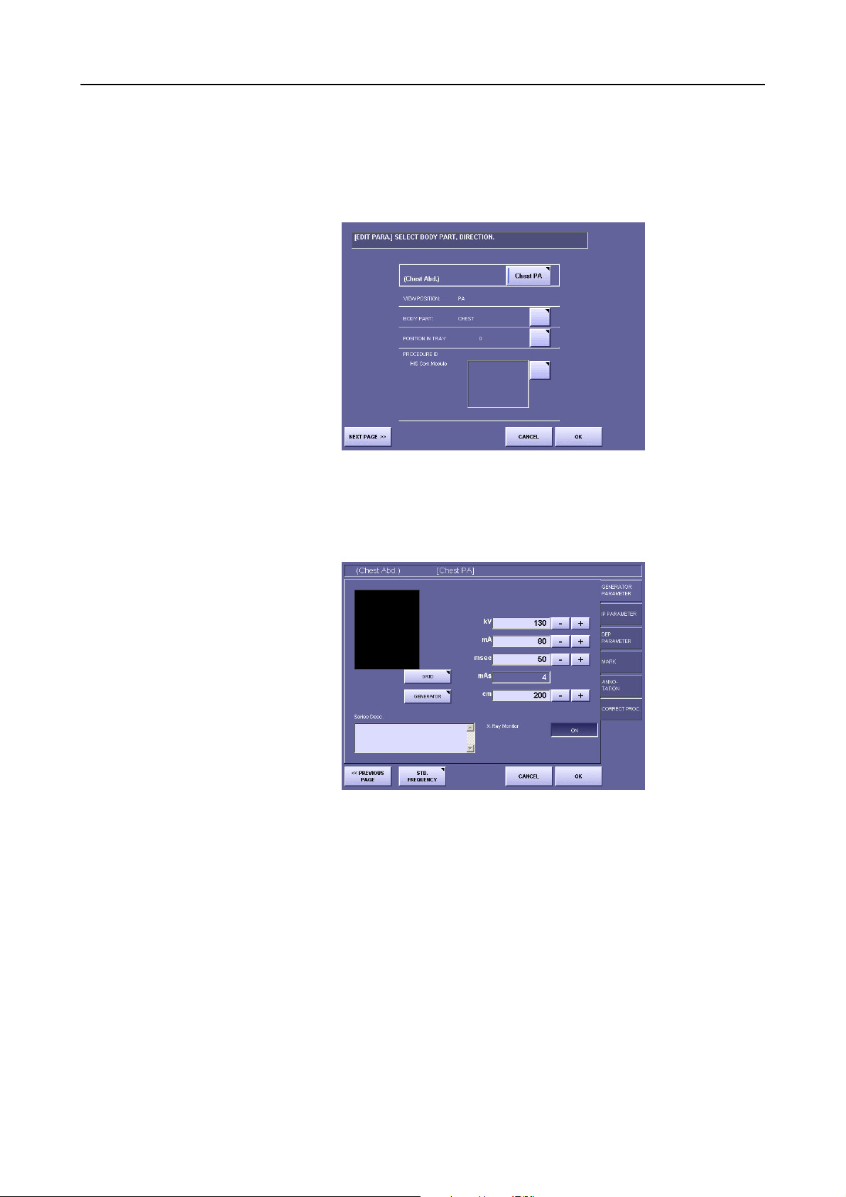
Select the Exposure Mode
4
Make sure that [EDIT PARA.] at the top-left is displayed in highlight, then select the
desired Exposure Mode.
The EDIT PARA. screen appears.
EDIT PARA. Screen (PREVIOUS PAGE)
Display the next page
5
Touch [NEXT PAGE].
EDIT PARA. Screen (NEXT PAGE)
– 4 –
Page 11
Continued on the following page >>
2.Edit Exposure Mode Settings
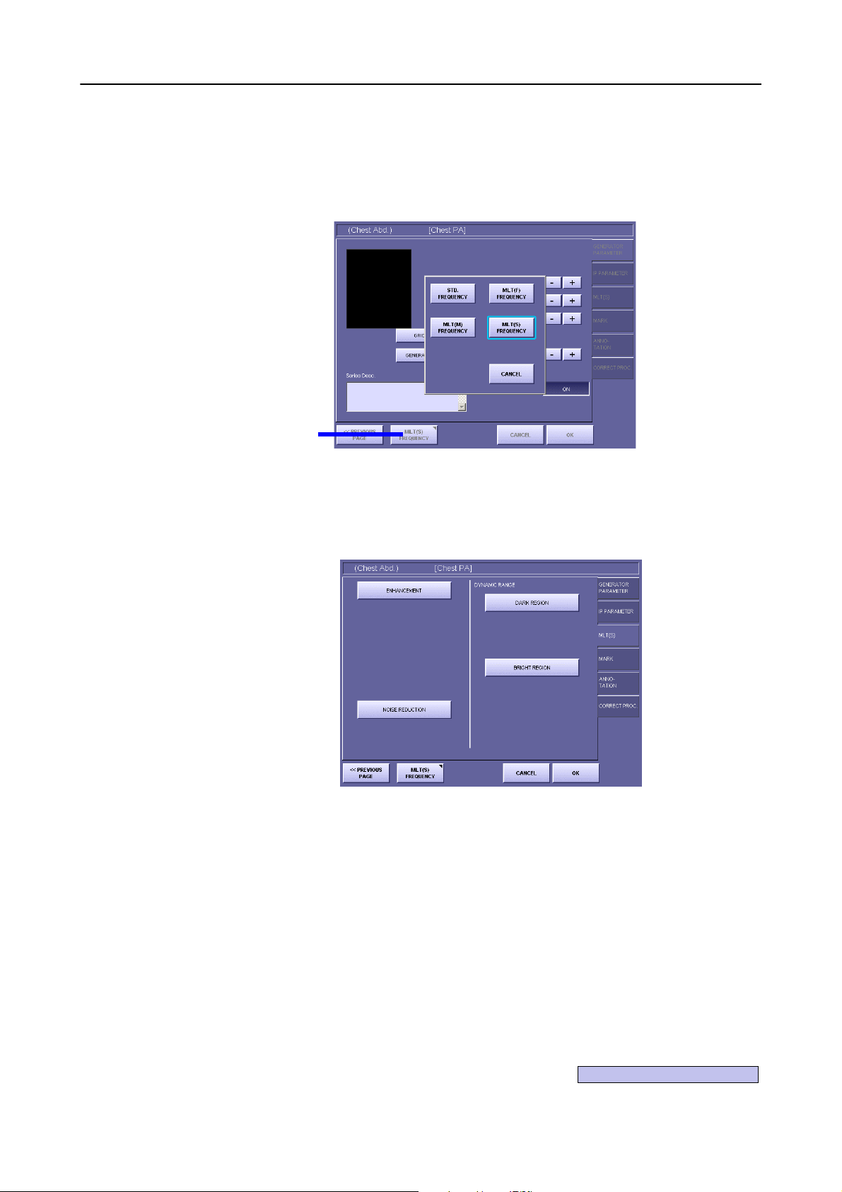
Frequency
Processing
Mode
Button
Select MLT (S) FREQUENCY
6
If MLT (S) FREQUENCY is not currently selected (in this case, the MLT(S) tab is not
displayed), touch the Frequency Processing Mode button to open the window, then
touch [MLT(S) FREQUENCY].
Frequency Processing Mode Window
Select the tab
7
Touch the MLT(S) tab.
Screen Appearance when MLT(S) FREQUENCY is Selected
Set the parameters
8
Set the parameters by referring to 2.2 Setting Enhancement (→ P. 7 ) , 2.3 Setting
Noise Reduction (→ P. 8 ) , and 2.4 Setting Dynamic Range Adjustment (→
P. 9) .
– 5 –
Page 12
2.Edit Exposure Mode Settings
Save the parameters
9
Touch [OK]. The window displaying the following message appears:
Save the changed parameter.
Then, touch [OK].
When Password is required
If the password is specified, a different message is displayed in the window as follows:
Administrator’s authority is needed. Enter system password.
In this case, touch anywhere within the frame to display On-Screen-Keyboard, type
your password, then touch [OK].
– 6 –
Page 13
2.2 Setting Enhancement
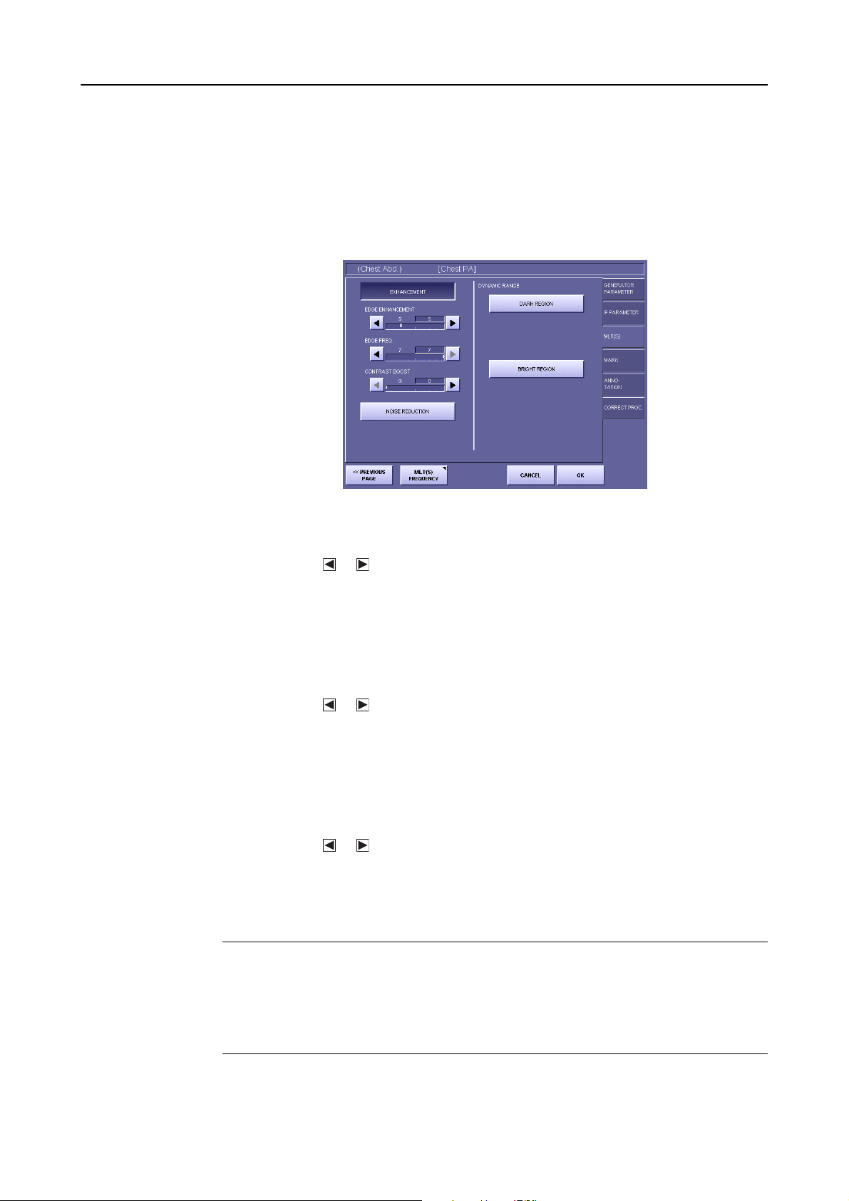
Enable enhancement
1
Each time [ENHANCEMENT] is touched, the setting switches between the highlight
(white outline characters against a colored background) and normal display. Edge
enhancement is enabled when in the highlighted state.
2.Edit Exposure Mode Settings
Screen Appearance when Enhancement is Enabled
Set the EDGE ENHANCEMENT parameter
2
Touch the or button, and set the degree of edge enhancement within the range
between 0 to 20.
The value on the left is the setting saved previously, and the value on the right is the
modified value.
This setting value determines the degree of edge enhancement. Larger values result in
more enhancement, and smaller values result in less enhancement.
Set the EDGE FREQ. parameter
3
Touch the or button, and set the edge frequency within the range between 1 to 7.
The value on the left is the setting saved previously, and the value on the right is the
modified value.
This setting value determines the frequency range for edge enhancement. Smaller values
enhance ranges containing low frequencies over high frequencies. Large values, on the
other hand, enhance high frequencies only.
Set the CONTRAST BOOST parameter
4
Touch the or button, and set the contrast boost within the range between 0 to 20.
The value on the left is the setting saved previously, and the value on the right is the
modified value.
This setting value is the degree of enhancement of the local contrast. Large values provide
more enhancement of the local contrast, and smaller values provide less enhancement.
NOTE: If the EDGE ENHANCEMENT and CONTRAST BOOST parameters under
the ENHANCEMENT are set to excessive values, artifacts may occur in the
image, or the effective data of the exposure image may be damaged. Check
the exposure image, and if the enhancement is too strong, either set the
EDGE ENHANCEMENT and CONTRAST BOOST to smaller values or
disable the enhancement.
– 7 –
Page 14
2.Edit Exposure Mode Settings
2.3 Setting Noise Reduction
Enable noise reduction
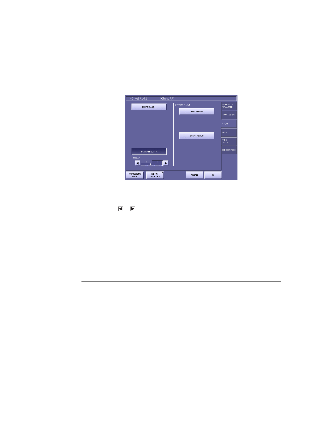
1
Each time [NOISE REDUCTION] is touched, the setting switches between the highlight (white outline characters against a colored background) and normal display. Noise
reduction is enabled when in the highlighted state.
Screen Appearance when Noise Reduction is Enabled
Set the EFFECT parameter
2
Touch the or button, and set the EFFECT parameter within the range between 1 to
10.
The value on the left is the setting saved previously, and the value on the right is the
modified value.
This value determines the degree of noise reduction. Larger values result in stronger
noise reduction, and smaller values result in weaker noise reduction.
NOTE: If the EFFECT parameter is set to an excessive value, artifacts can occur in
the image, or the effective data of the exposure image may be damaged.
Check the exposure image, and if noise reduction is too strong, either set the
EFFECT parameter to a smaller value or disable the setting.
– 8 –
Page 15
2.4 Setting Dynamic Range Adjustment
2.4.1 Setting high-density sections
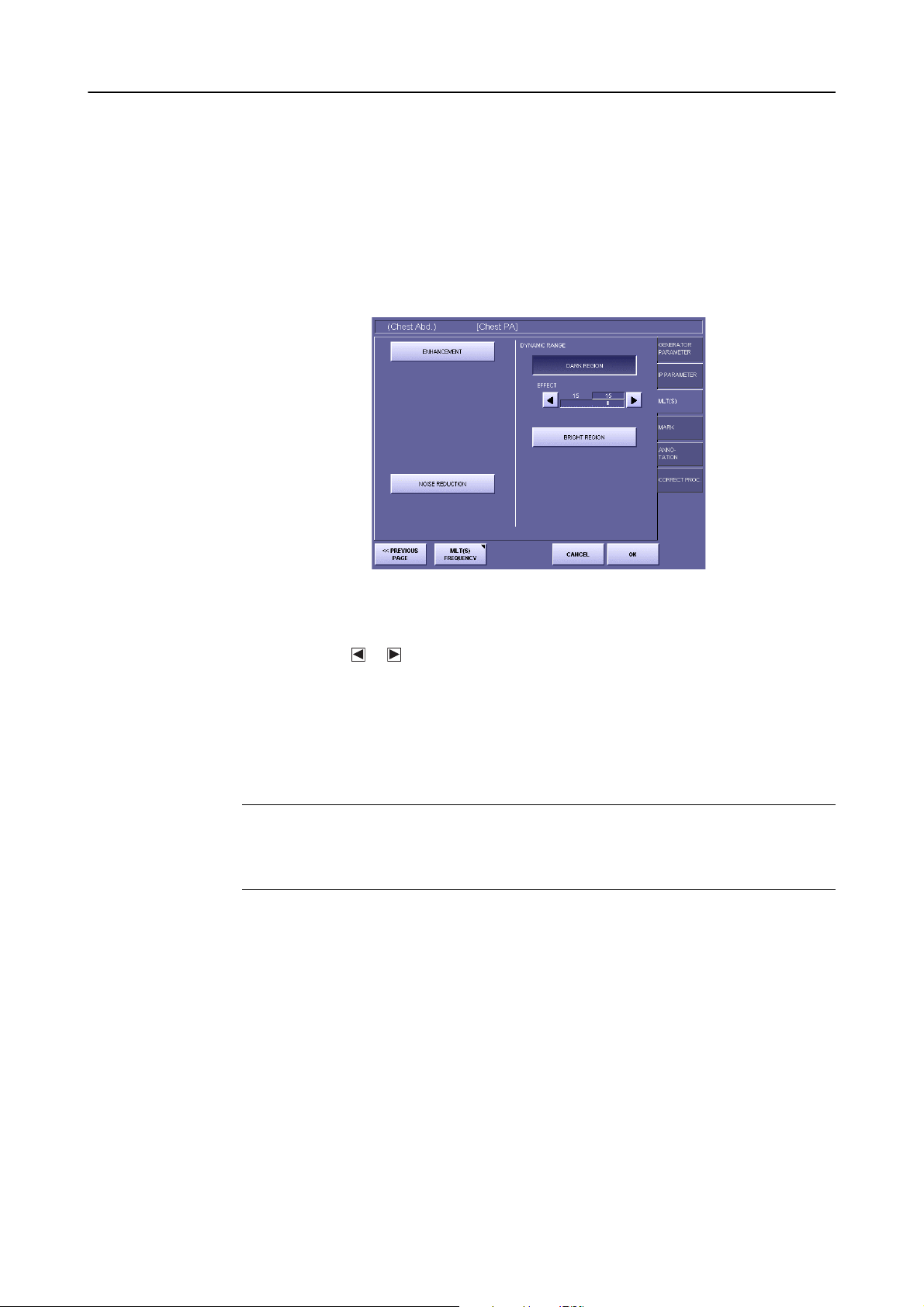
Enable dynamic range adjustment (DARK REGION)
1
Each time [DARK REGION] is touched, the setting switches between the highlight
(white outline characters against a colored background) and normal display. This is
enabled when in the highlighted state.
2.Edit Exposure Mode Settings
Screen Appearance when Dynamic Range Adjustment (DARK REGION) is Enabled
Set the maximum density
2
Touch the or button, and set the EFFECT parameter within the range between 1 to
20.
The value on the left is the setting saved previously, and the value on the right is the
modified value.
This value determines the maximum density assigned to the subject range. Larger values
result in higher maximum densities, and smaller densities result in lower maximum densities.
NOTE: If the EFFECT parameter is set to a value that is too low, artifacts can occur
in the image, or the effective data of the exposure image may be damaged.
Check the exposure image, and if the image is proccessed excessively, either
set to a larger maximum density or disable the setting.
– 9 –
Page 16
2.Edit Exposure Mode Settings
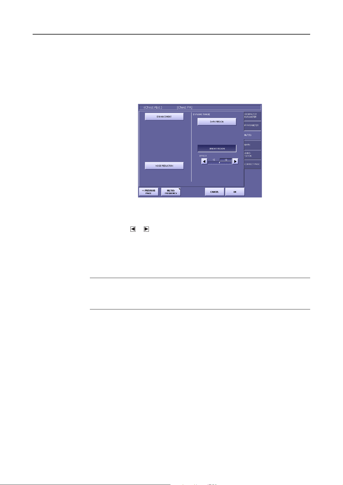
2.4.2 Setting low-density sections
Enable dynamic range adjustment (BRIGHT REGION)
1
Each time [BRIGHT REGION] is touched, the setting switches between the highlight
(white outline characters against a colored background) and normal display. This is
enabled when in the highlighted state.
Screen Appearance when Dynamic Range Adjustment (BRIGHT REGION) is Enabled
Set the minimum density
2
Touch the or button, and set the EFFECT parameter within the range between 1 to
20.
The value on the left is the setting saved previously, and the value on the right is the
modified value.
This value determines the minimum density assigned to the subject range. Larger values
result in higher minimum densities, and smaller values result in lower minimum densities.
NOTE: If the EFFECT parameter is set to a value that is too high, artifacts can occur
in the image, or the effective data of the exposure image may be damaged.
Check the exposure image, and if the image is proccessed excessively, either
set to a smaller minimum density or disable the setting.
– 10 –
Page 17
Continued on the following page >>
3. QA Mode Settings
3.1 Procedures to Change Parameters
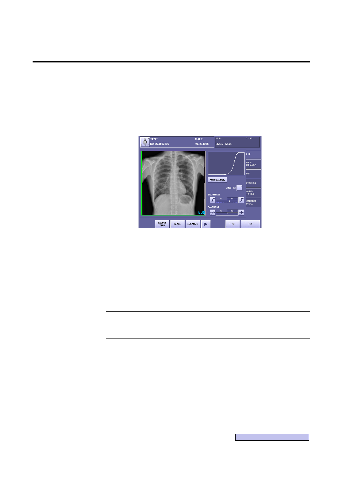
Image processing of exposure image with CXDI is called QA (Quality Assurance) Processing,
and can be performed by adjusting the parameters on the QA Mode screen to optimize the exposure image.
Display the QA Mode screen
1
Display the QA Mode screen by one of the following methods:
QA Mode Screen
To display the QA Mode screen automatically right after x-ray exposure
On the Exposure screen, touch the followings to display the DISPLAYING PARAMETER CHANGE/QA SCREEN DURING EXPOSURE screen:
[SYSTEM] > [SETUP MENU] > [SYSTEM SETUP] > [DISPLAYING PARAMETER CHANGE/QA SCREEN DURING EXPOSURE]
Then set the QA Mode screen effective.
To perform QA Processing right after x-ray exposure
Touch [QA] on the Preview screen.
To perform QA Processing after examination
Select the exposure image from the Study List, display the selected image, then touch
[QA].
– 11 –
Page 18
3.QA Mode Settings
Frequency
Processing
Mode
Button
Select MLT(S) FREQUENCY
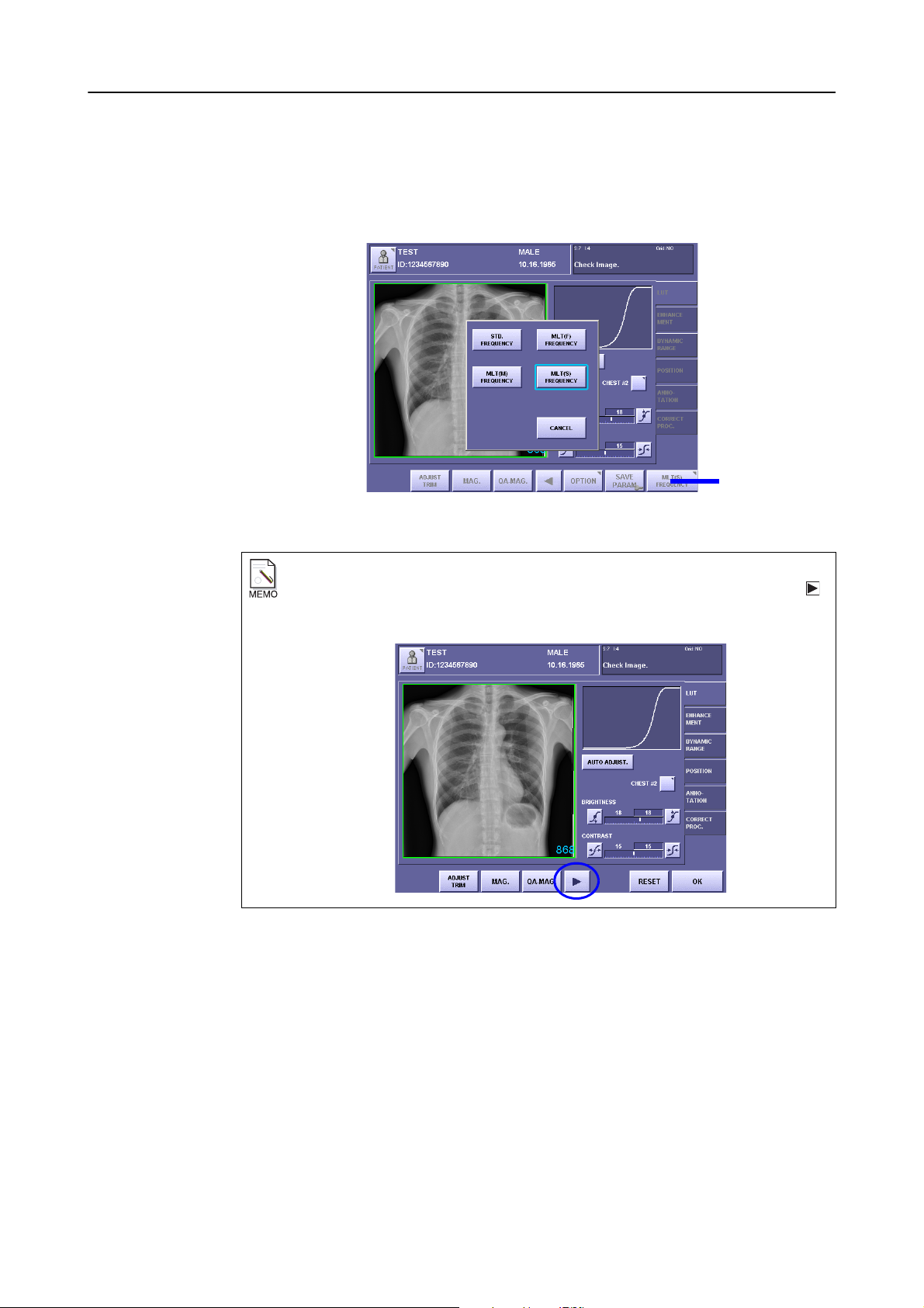
2
If MLT(S) FREQUENCY is not currently selected (in this case, the ENHANCEMENT
and DYNAMIC RANGE tabs are not displayed), touch the Frequency Processing Mode
button to open the window, then touch [MLT(S) FREQUENCY].
Frequency Processing Mode Window
When the Frequency Processing Mode button is not visible
If the Frequency Processing Mode button is not displayed on the screen, touch the
button at the bottom part of the screen.
Select the tab
3
To change enhancement and noise reduction, touch the ENHANCEMENT tab.
To change the dynamic range adjustment, touch the DYNAMIC RANGE tab.
Change the parameters
4
Change the parameters by referring to 3.2 Changing Enhancement (→ P. 1 4 ) ,
3.3 Changing Noise Reduction (→ P.15), and 3.4 Changing Dynamic Range
Adjustment (→ P.16).
– 12 –
Page 19
3.QA Mode Settings
Save the new parameters
5
To save new parameters as the default values of the Exposure Mode (except opening
from Study List), touch [SAVE PARAM]. The window displaying the following message
appears:
Are you sure you want to change the default generator parameters?
Then, touch [YES].
When Password is required
If the password is specified, a different message is displayed as follows:
Administrator’s authority is needed. Enter system password.
In this case, touch within the frame to display On-Screen-Keyboard, type your
password, then touch [OK].
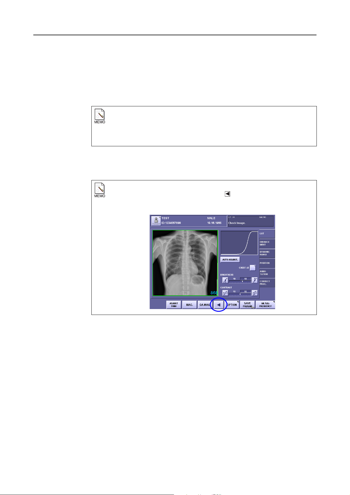
Close the QA Mode screen
6
Touch [OK].
When [OK] is not visible on the screen
If [OK] is not displayed on the screen, touch the button at the bottom part of the
screen.
– 13 –
Page 20
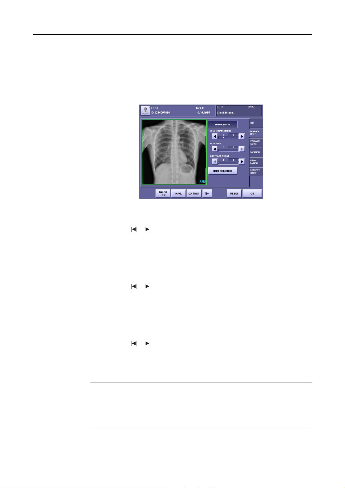
3.QA Mode Settings
3.2 Changing Enhancement
Enable enhancement
1
Each time [ENHANCEMENT] is touched, the setting switches between the highlight
(white outline characters against a colored background) and normal display. This is
enabled when in the highlighted state.
Screen Appearance when Enhancement is Enabled
Set the EDGE ENHANCEMENT parameter
2
Touch the or button, and set the degree of edge enhancement within the range
between 0 to 20.
The value on the left is the setting saved previously, and the value on the right is the
modified value.
This setting value determines the degree of edge enhancement. Larger values result in
more enhancement, and smaller values result in less enhancement.
Set the EDGE FREQ. parameter
3
Touch the or button, and set the edge frequency within the range between 1 to 7.
The value on the left is the setting saved previously, and the value on the right is the
modified value.
This setting value determines the frequency range for edge enhancement. Smaller values
enhance ranges containing low frequencies over high frequencies. Large values, on the
other hand, enhance high frequencies only.
Set the CONTRAST BOOST parameter
4
Touch the or button, and set the contrast boost within the range between 0 to 20.
The value on the left is the setting saved previously, and the value on the right is the
modified value.
This setting value is the degree of enhancement of the local contrast. Large values provide
more enhancement of the local contrast, and smaller values provide less enhancement.
NOTE: If the EDGE ENHANCEMENT and CONTRAST BOOST parameters under
the ENHANCEMENT are set to excessive values, artifacts may occur in the
image, or the effective data of the exposure image may be damaged. Check
the exposure image, and if the enhancement is too strong, either set the
EDGE ENHANCEMENT and CONTRAST BOOST to smaller values or
disable the enhancement.
– 14 –
Page 21
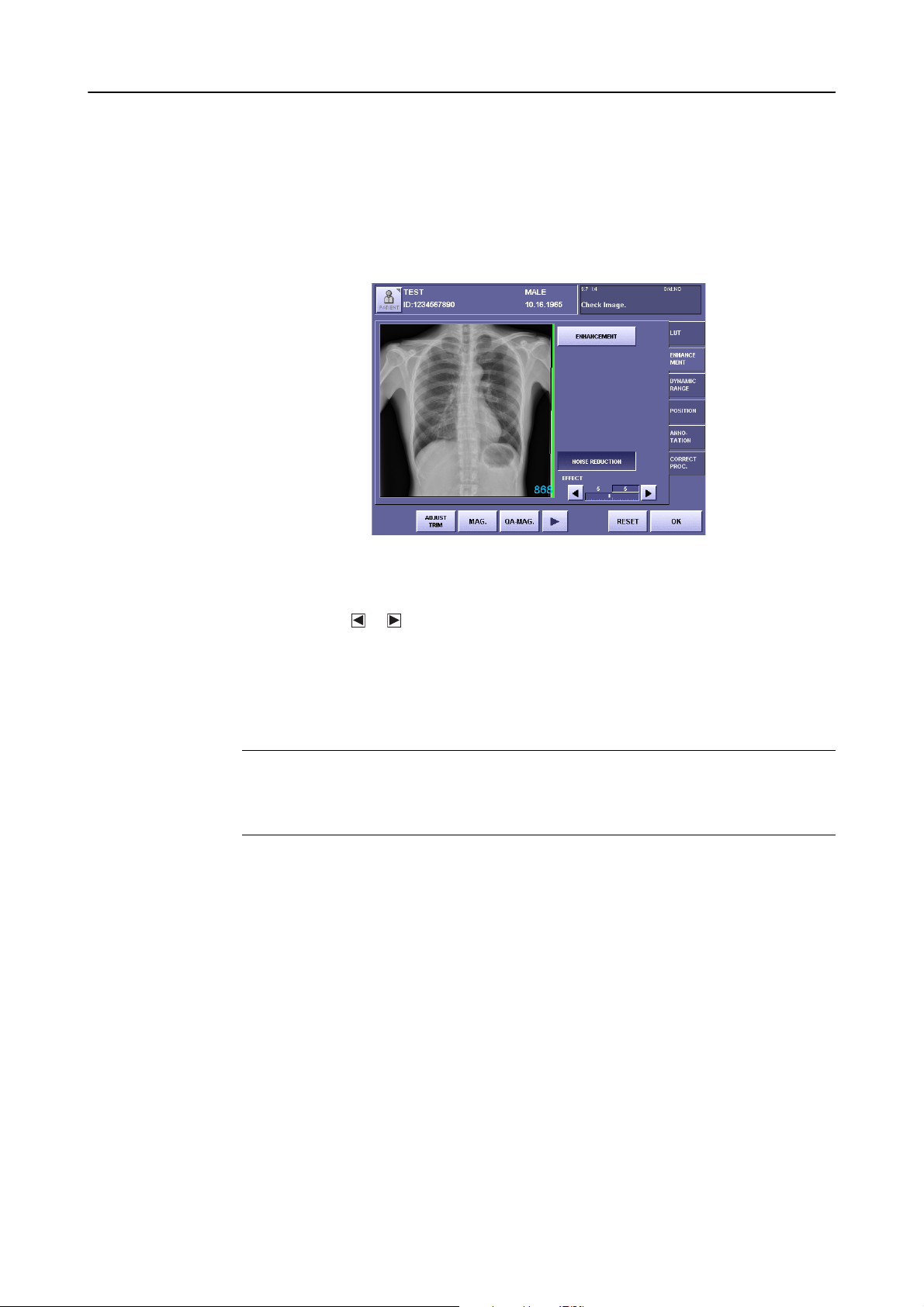
3.3 Changing Noise Reduction
Enable noise reduction
1
Each time [NOISE REDUCTION] is touched, the setting switches between the highlight (white outline characters against a colored background) and normal display. Noise
reduction is enabled when in the highlighted state.
3.QA Mode Settings
Screen Appearance when Noise Reduction is Enabled
Set the EFFECT parameter
2
Touch the or button, and set the EFFECT parameter within the range between 1 to
10.
The value on the left is the setting saved previously, and the value on the right is the
modified value.
This value determines the degree of noise reduction. Larger values result in stronger
noise reduction, and smaller values result in weaker noise reduction.
NOTE: If the EFFECT parameter is set to an excessive value, artifacts can occur in
the image, or the effective data of the exposure image may be damaged.
Check the exposure image, and if noise reduction is too strong, either set the
EFFECT parameter to a smaller value or disable the setting.
– 15 –
Page 22
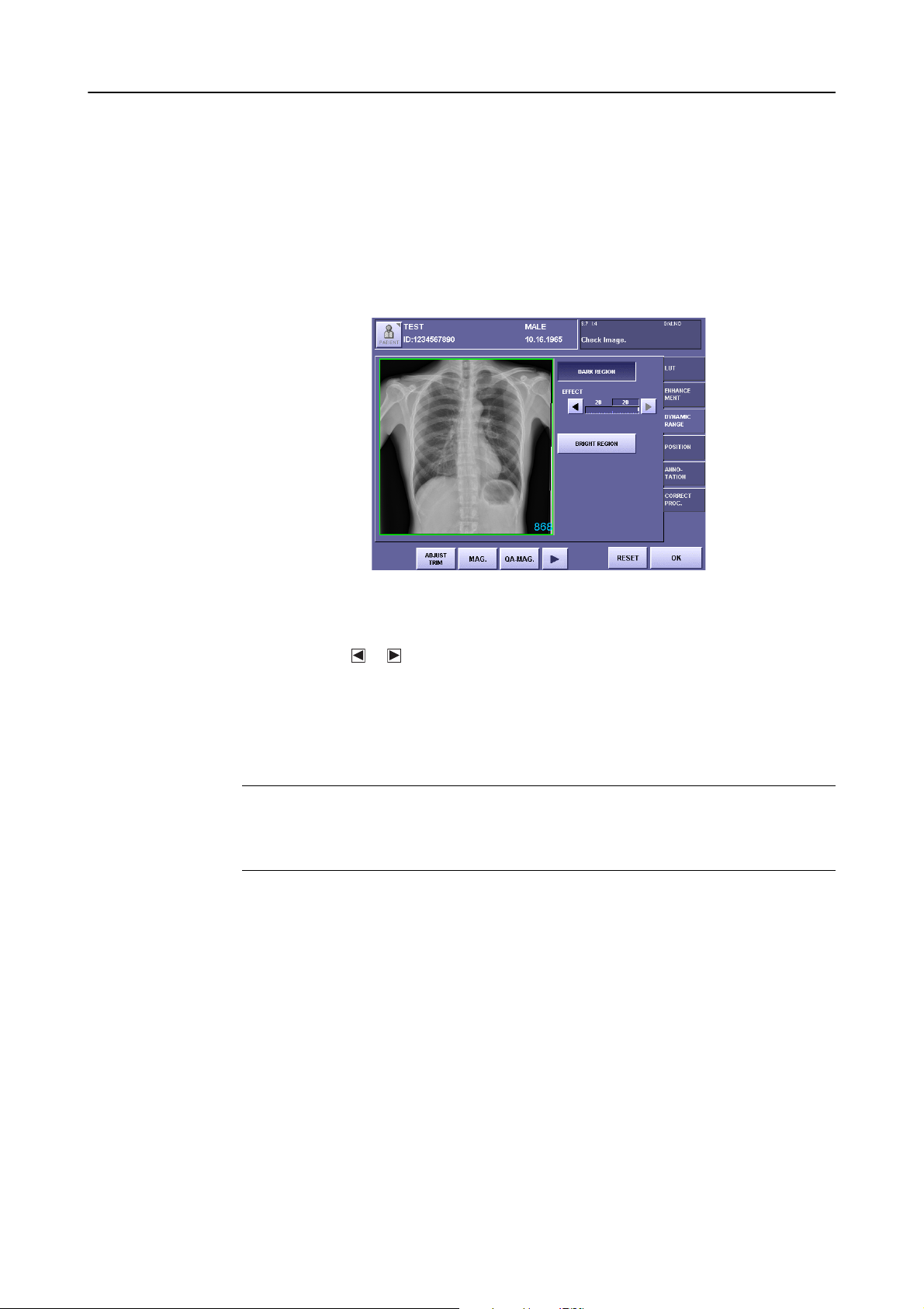
3.QA Mode Settings
3.4 Changing Dynamic Range Adjustment
3.4.1 Changing high-density sections
Enable dynamic range adjustment (DARK REGION)
1
Each time [DARK REGION] is touched, the setting switches between the highlight
(white outline characters against a colored background) and normal display. This is
enabled when in the highlighted state.
Screen Appearance when Dynamic Range Adjustment (DARK REGION) is Enabled
Set the maximum density
2
Touch the or button, and set the EFFECT parameter within the range between 1 to
20.
The value on the left is the setting saved previously, and the value on the right is the
modified value.
This value determines the maximum density assigned to the subject range. Larger values
result in higher maximum densities, and smaller values result in lower maximum densities.
NOTE: If the EFFECT parameter is set to a value that is too low, artifacts can occur
in the image, or the effective data of the exposure image may be damaged.
Check the exposure image, and if the image is proccessed excessively, either
set to a larger maximum density or disable the setting.
– 16 –
Page 23
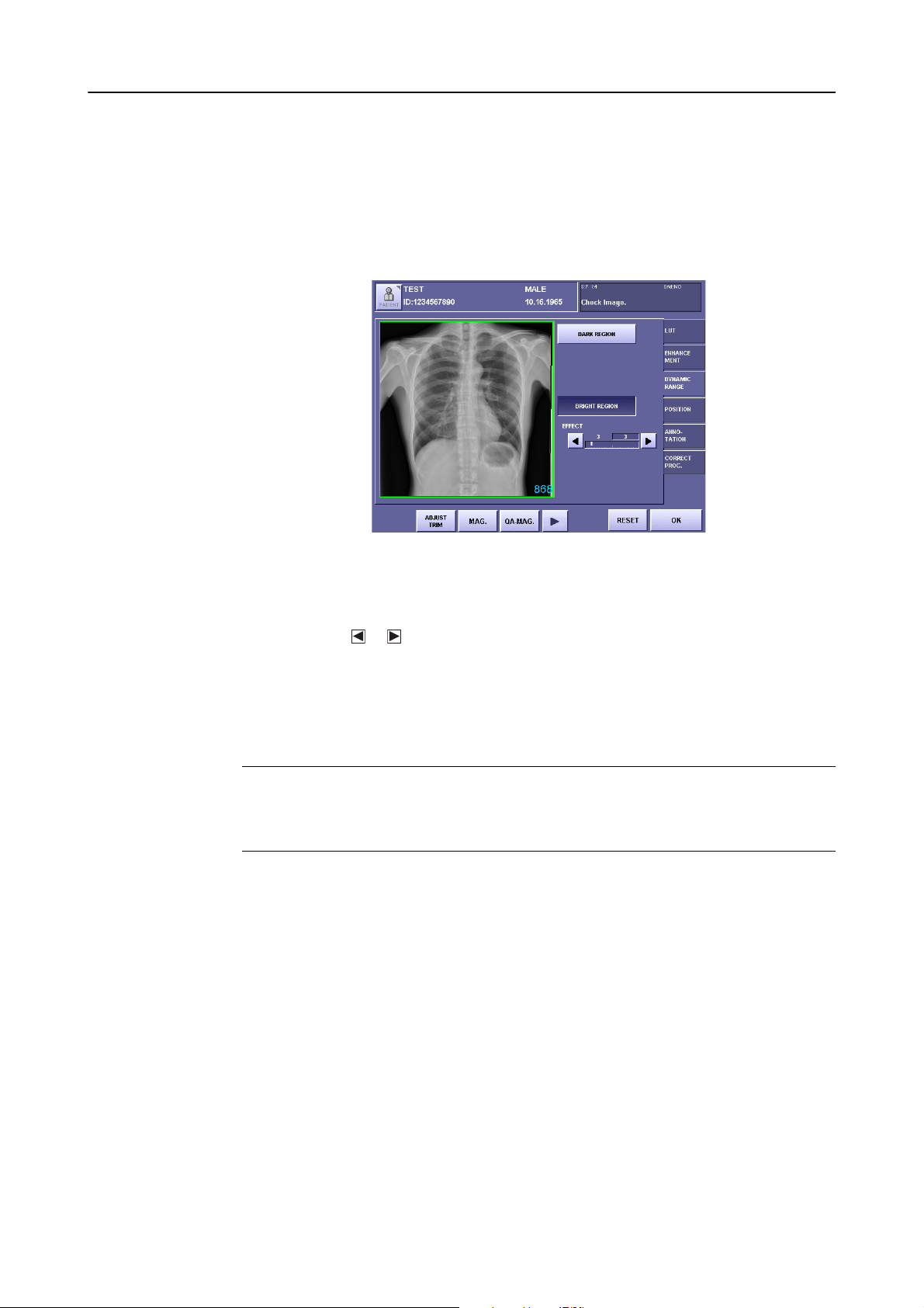
3.4.2 Changing low-density sections
Enable dynamic range adjustment (BRIGHT REGION)
1
Each time [BRIGHT REGION] is touched, the setting switches between the highlight
(white outline characters against a colored background) and normal display. This is
enabled when in the highlighted state.
3.QA Mode Settings
Screen Appearance when Dynamic Range Adjustment (BRIGHT REGION) is Enabled
Set the minimum density
2
Touch the or button, and set the EFFECT parameter within the range between 1 to
20.
The value on the left is the setting saved previously, and the value on the right is the
modified value.
This value determines the minimum density assigned to the subject range. Larger values
result in higher minimum densities, and smaller values result in lower minimum densities.
NOTE: If the EFFECT parameter is set to a value that is too high, artifacts can occur
in the image, or the effective data of the exposure image may be damaged.
Check the exposure image, and if the image is proccessed excessively, either
set to a smaller minimum density or disable the setting.
– 17 –
Page 24

4. QA Parameters
When MLT (S) frequency processing is selected, the QA parameters (%IP_PARAM%) in
Annotation are displayed in the format below.
REX680 Q3 E5,7,0 D20,3 N5 GCS18,15 R RT+90 Z0 M2,1,1 P1
This section describes the parameters specific to the MLT(S) (underlined 1 to 4).
For details about the other parameters, please refer to the Operation Manual (Setup Guide).
1 Frequency Processing Mode
If MLT (S) FREQUENCY is selected, Q3 is displayed.
2 Enhancement
The parameter is displayed as: E edge enhancement, edge frequency, contrast boost
Nothing is displayed if the enhancement is disabled.
3 Dynamic Range Adjustment
The parameter is displayed as: D Maximum density, minimum density
Nothing is displayed if both the DARK REGION and BRIGHT REGION are disabled.
If the DARK REGION only is disabled, the parameter is displayed as D*, 3, and if the
BRIGHT REGION only is disabled, it is displayed as D20, *.
12 34
4 Noise Reduction
The parameter is displayed as: N Effect
Nothing is displayed if NOISE REDUCTION setting is disabled.
– 18 –
Page 25

Page 26

Page 27

Page 28

CANON INC. Medical Equipment Group
30-2, Shimomaruko 3-chome, Ohta-ku, Tokyo, Japan
Telephone: (81)-3-3758-2111
CANON U.S.A., INC.
CANON MEDICAL SYSTEMS
15955 Alton Parkway, Irvine, CA 92618-3616, U.S.A.
Telephone: (1)-949-753-4160
CANON EUROPA N.V. Medical Products Division
Bovenkerkerweg 59-61, 1185 XB Amstelveen, The Netherlands
Telephone: (31)-20-545-8926
PUB. L-IE-4146A
 Loading...