

Canon MF720 Series, MF727Cdw, MF726Cdw, MF724Cdw, MF728Cdw Service Manual
...
MF720 Series
Service Manual
Revision 2.0

1x
1x
Introduction
Introduction
Important Notices
Application
This manual has been issued by Canon Inc. for qualified persons to learn technical theory, installation, maintenance, and repair
of products.
This manual covers all localities where the products are sold. For this reason, there may be information in this manual that does
not apply to your locality.
Corrections
This manual may contain technical inaccuracies or typographical errors due to improvements or changes in products.
When changes occur in applicable products or in the contents of this manual, Canon will release technical information as the
need arises. In the event of major changes in the contents of this manual over a long or short period, Canon will issue a new
edition of this manual.
The following paragraph does not apply to any countries where such provisions are inconsistent with local law.
Trademarks
The product names and company names used in this manual are the registered trademarks of the individual companies.
Copyright
This manual is copyrighted with all rights reserved. Under the copyright laws, this manual may not be copied, reproduced or
translated into another language, in whole or in part, without the consent of Canon Inc.
© CANON INC. 2015
Caution
Use of this manual should be strictly supervised to avoid disclosure of confidential information.
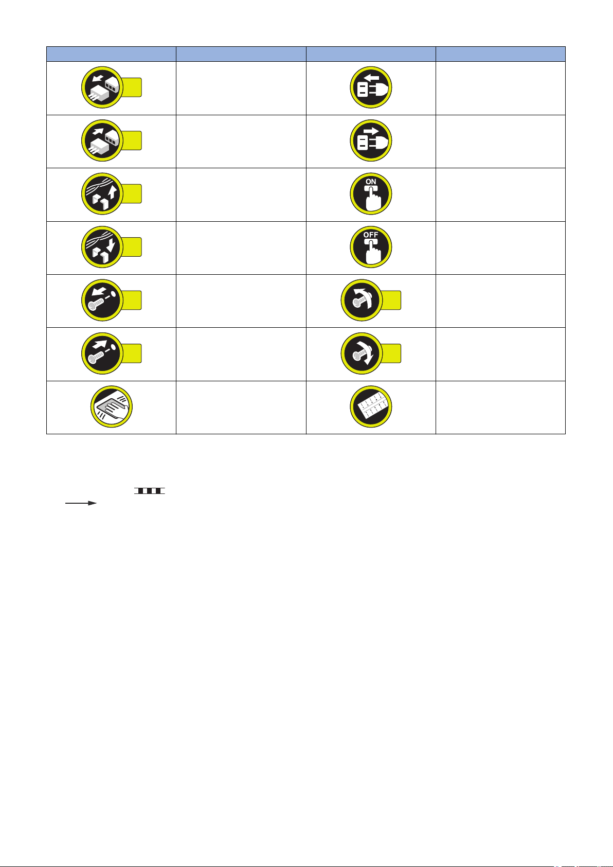
Explanation of Symbols
The following symbols are used throughout this Service Manual.
Symbols Explanation Symbols Explanation
Check.
Remove the claw.
Check visually.
Check a sound. Push the part.
Insert the claw.
1x
1x
1x
1x
1x
1x
1x
1x
Introduction
Symbols Explanation Symbols Explanation
Disconnect the connector. Connect the power cable.
Connect the connector. Disconnect the power cable.
Remove the cable/wire from the
cable guide or wire saddle.
Install the cable/wire to the cable
guide or wire saddle.
Remove the screw.
Install the screw.
Cleaning is needed. Measurement is needed.
The following rules apply throughout this Service Manual:
1. Each chapter contains sections explaining the purpose of specific functions and the relationship between electrical and
mechanical systems with reference to the timing of operation.
In the diagrams, represents the path of mechanical drive; where a signal name accompanies the symbol, the arrow
indicates the direction of the electric signal.
The expression "turn on the power" means flipping on the power switch, closing the front door, and closing the delivery unit
door, which results in supplying the machine with power.
2. In the digital circuits, '1' is used to indicate that the voltage level of a given signal is "High", while '0' is used to indicate "Low".
(The voltage value, however, differs from circuit to circuit.) In addition, the asterisk (*) as in "DRMD*" indicates that the DRMD
signal goes on when '0'.
In practically all cases, the internal mechanisms of a microprocessor cannot be checked in the field. Therefore, the operations
of the microprocessors used in the machines are not discussed: they are explained in terms of from sensors to the input of
the DC controller PCB and from the output of the DC controller PCB to the loads.
The descriptions in this Service Manual are subject to change without notice for product improvement or other purposes, and
major changes will be communicated in the form of Service Information bulletins.
All service persons are expected to have a good understanding of the contents of this Service Manual and all relevant Service
Information bulletins and be able to identify and isolate faults in the machine.
Turn on the power.
Turn off the power.
Loosen the screw.
Tighten the screw.

Contents
Contents
Safety Precautions...............................................................................................1
Laser Safety........................................................................................................................................ 2
How to Handle the Laser Scanner Unit...............................................................................................2
Toner Safety........................................................................................................................................2
About Toner..........................................................................................................................................2
Handling Adhered Toner........................................................................................................................2
Notes When Handling a Lithium Battery............................................................................................. 3
Notes on Assembly/Disassembly........................................................................................................3
1. Product Overview.............................................................................................4
Product Lineups.................................................................................................................................. 5
Host Machine........................................................................................................................................5
Options................................................................................................................................................ 6
Product Features.................................................................................................................................7
Features...............................................................................................................................................7
Specifications...................................................................................................................................... 8
Specifications of Host Machine.............................................................................................................. 8
ADF Specifications..............................................................................................................................10
Wireless LAN Specifications................................................................................................................ 10
SEND Specifications........................................................................................................................... 11
FAX Specifications.............................................................................................................................. 12
Paper types / Paper size......................................................................................................................13
Name of Parts................................................................................................................................... 14
External View......................................................................................................................................14
Cross Section View............................................................................................................................. 16
Control Panel......................................................................................................................................18
2. Technical Explanation................................................................................... 19
Basic Configuration........................................................................................................................... 20
Configuration function..........................................................................................................................20
Basic Sequence..................................................................................................................................20
Document Exposure/Feeder System................................................................................................ 22
Document Exposure System................................................................................................................22
Document Feeder System................................................................................................................... 23
Controller System..............................................................................................................................26
Overview............................................................................................................................................ 26
Controls..............................................................................................................................................26
Laser Control System........................................................................................................................29
Overview............................................................................................................................................ 29
Controls..............................................................................................................................................29
Image Formation System.................................................................................................................. 30
Overview............................................................................................................................................ 30
Parts.................................................................................................................................................. 30
Image Forming Process.......................................................................................................................30
i

Contents
Controls..............................................................................................................................................35
Fixing System....................................................................................................................................41
Overview............................................................................................................................................ 41
Controls..............................................................................................................................................41
Pickup / Feed System....................................................................................................................... 44
Overview............................................................................................................................................ 44
Parts Configuration..............................................................................................................................44
Drive Configuration..............................................................................................................................45
Controls..............................................................................................................................................45
Embedded RDS................................................................................................................................ 48
Product Overview................................................................................................................................48
Service cautions..................................................................................................................................48
E-RDS Setup...................................................................................................................................... 49
FAQ................................................................................................................................................... 51
Troubleshooting.................................................................................................................................. 53
Error code and strings......................................................................................................................... 54
Setting Information Export/Import Function (DCM)........................................................................... 58
Function Overview.............................................................................................................................. 58
Specifications..................................................................................................................................... 60
Limitations.......................................................................................................................................... 62
Procedure for Exporting/Importing Service Mode Setting Information......................................................64
List of Items Which Can Be Imported....................................................................................................73
3. Periodical Service.......................................................................................... 93
Periodically Replaced Parts.............................................................................................................. 94
Durable Parts.................................................................................................................................... 95
Periodical Services............................................................................................................................96
Cleaning............................................................................................................................................ 97
4. Disassembly/Assembly................................................................................. 98
List of Parts....................................................................................................................................... 99
List of External / Internal Cover............................................................................................................ 99
List of Main Unit................................................................................................................................ 101
List of Motor / Fan............................................................................................................................. 103
List of Clutch / Solenoid / Heater / Thermistor / Switch / Speaker..........................................................104
List of Sensor....................................................................................................................................105
PCB................................................................................................................................................. 106
List of Connector...............................................................................................................................108
External Cover, Internal Cover........................................................................................................116
Location............................................................................................................................................116
External Cover, Internal Cover Disassembly/Assembly Procedure................................................ 118
Removing the Left Cover................................................................................................................... 118
Removing the Right Cover................................................................................................................. 120
Removing the Right Front Cover........................................................................................................ 121
Removing the Front Cover................................................................................................................. 122
Removing the Rear Upper Cover........................................................................................................123
Removing the Rear Cover..................................................................................................................123
Removing the Rear Lower Cover........................................................................................................123
Removing the Rear Cover Rib Unit.....................................................................................................125
ii

Contents
Removing the Upper Cover................................................................................................................125
Removing the Cartridge Tray............................................................................................................. 127
Document Exposure, Feed System.................................................................................................128
Location............................................................................................................................................128
Document Exposure, Feed System Disassembly/Assembly Procedure......................................... 130
Removing the ADF Unit + Reader Unit................................................................................................130
Separating the ADF Unit + Reader Unit.............................................................................................. 131
Removing the ADF Roller Unit............................................................................................................136
Removing the ADF Pickup Roller....................................................................................................... 137
Removing the ADF Separation Roller................................................................................................. 138
Removing the ADF Separation Pad.................................................................................................... 138
Removing the ADF Pickup Feed Unit..................................................................................................140
Removing the ADF Pickup Motor........................................................................................................141
Removing the Scoopup sheet holder.................................................................................................. 142
Removing the Reader Unit Upper Cover............................................................................................. 144
Removing the CIS Unit...................................................................................................................... 146
Removing the Reader Scanner Motor.................................................................................................151
Controller System............................................................................................................................154
Location............................................................................................................................................154
Controller System Disassembly/Assembly Procedure.................................................................... 157
Removing the Controller Cover.......................................................................................................... 157
Removing the Wireless LAN PCB (MF728Cdw / 727Cdw / 724Cdw).....................................................157
Removing the Main Controller PCB.................................................................................................... 157
Removing the Main Controller Support Plate.......................................................................................161
Removing the DC Controller PCB.......................................................................................................162
Removing the High Voltage Power Supply PCB.................................................................................. 163
Removing the Low Voltage Unit..........................................................................................................165
Removing the Fixing Sub PCB........................................................................................................... 166
Removing the Driver PCB.................................................................................................................. 167
Removing the Relay PCB.................................................................................................................. 168
Removing the Control Panel Unit........................................................................................................169
Removing the NFC PCB (MF727Cdw / 726Cdw).................................................................................171
Removing the FAX PCB (MF728Cdw / 727Cdw / 725Cdw).................................................................. 171
Removing the Off Hook PCB (MF728Cdw / 727Cdw / 725Cdn)............................................................ 172
Removing the Main Drive Unit............................................................................................................172
Removing the Duplex Reverse Drive Unit........................................................................................... 179
Removing the Fixing/Fixing Power Supply Cooling Fan Unit.................................................................180
Removing the Duplex Feeding Fan.....................................................................................................181
Removing the Speaker (MF728Cdw / 727Cdw / 725Cdn).....................................................................183
Laser Exposure System.................................................................................................................. 184
Location............................................................................................................................................184
Laser Exposure System Disassembly/Assembly Procedure...........................................................185
Removing the Laser Scanner Unit...................................................................................................... 185
Image Formation System................................................................................................................ 190
Location............................................................................................................................................190
Image Formation System Disassembly/Assembly Procedure.........................................................191
Removing the ITB Unit.......................................................................................................................191
Removing the Patch Density and Registration Sensor unit................................................................... 193
Removing the Developing Motor.........................................................................................................195
Removing the Drum Motor................................................................................................................. 196
Removing the Secondary Transfer Outer Roller...................................................................................198
iii

Contents
Fixing System..................................................................................................................................199
Location............................................................................................................................................199
Fixing System Disassembly/Assembly Procedure.......................................................................... 200
Removing the Fixing Assembly.......................................................................................................... 200
Removing the Fixing Film Unit............................................................................................................201
Removing the Fixing Pressure Roller..................................................................................................205
Removing the Fixing Motor Unit..........................................................................................................205
Pickup Feeder System.................................................................................................................... 208
Location............................................................................................................................................208
Pickup Feeder System Disassembly/Assembly Procedure.............................................................209
Removing the Cassette Pickup Roller.................................................................................................209
Removing the Cassette Separation Roller...........................................................................................210
Removing the MP Tray Pickup Roller..................................................................................................211
Removing the MP Tray Separation Pad.............................................................................................. 211
Removing the Pickup Motor............................................................................................................... 212
Removing the Pickup Unit..................................................................................................................213
Removing the MP Tray Pickup Unit.................................................................................................... 218
Removing the Secondary Transfer Feed Unit...................................................................................... 219
Removing the Delivery Unit................................................................................................................220
Removing the Duplex Feed Unit.........................................................................................................221
Removing the Re-pickup Guide Unit................................................................................................... 222
5. Adjustment................................................................................................... 224
Overview......................................................................................................................................... 225
Adjustment at Parts Replacement...................................................................................................226
Document Exposure / Feed System....................................................................................................226
Controller System..............................................................................................................................234
Laser Exposure System.....................................................................................................................239
6. Troubleshooting...........................................................................................240
Test Print.........................................................................................................................................241
Engine test print................................................................................................................................ 241
Controller test print............................................................................................................................ 241
Trouble shooting items....................................................................................................................243
Recurring faulty image.......................................................................................................................243
Confirming nip width..........................................................................................................................243
Version Upgrade............................................................................................................................. 244
Overview.......................................................................................................................................... 244
Upgrading by UST.............................................................................................................................244
Preparation.......................................................................................................................................244
Downloading System Software...........................................................................................................245
Upgrading via Internet....................................................................................................................... 247
Debug Log ......................................................................................................................................248
Function Overview.............................................................................................................................248
Conditions for collecting logs..............................................................................................................248
Collection procedure..........................................................................................................................248
7. Error/Jam/Alarm........................................................................................... 250
Outline.............................................................................................................................................251
iv

Contents
Outline..............................................................................................................................................251
Jam code..........................................................................................................................................251
Error Codes.....................................................................................................................................252
Jam Code........................................................................................................................................257
8. Service Mode................................................................................................ 259
Overview......................................................................................................................................... 260
Service Mode Menu...........................................................................................................................260
Backing up Service Mode.................................................................................................................. 260
Screen flow of Service mode..............................................................................................................261
Remote UI service mode....................................................................................................................262
COPIER...........................................................................................................................................264
DISPLAY.......................................................................................................................................... 264
I/O....................................................................................................................................................265
ADJUST........................................................................................................................................... 266
FUNCTION.......................................................................................................................................277
OPTION........................................................................................................................................... 290
COUTER.......................................................................................................................................... 295
FEEDER..........................................................................................................................................300
ADJUST........................................................................................................................................... 300
FUNCTION.......................................................................................................................................301
FAX................................................................................................................................................. 302
Lis of SSSW..................................................................................................................................... 302
List of MENU.....................................................................................................................................303
List of NUM.......................................................................................................................................303
Setting of NCU Parameters................................................................................................................304
TESTMODE.................................................................................................................................... 308
PRINT.............................................................................................................................................. 308
FAX..................................................................................................................................................309
APPENDICES....................................................................................................314
Service Tools...................................................................................................................................315
Special Tools.................................................................................................................................... 315
Solvents and Oils.............................................................................................................................. 315
General Circuit Diagram..................................................................................................................316
Print Sequence................................................................................................................................317
Backup Data ...................................................................................................................................318
v

Safety Precautions
Laser Safety..........................................2
How to Handle the Laser Scanner Unit
...........................................................2
Toner Safety..........................................2
Notes When Handling a Lithium
Battery............................................... 3
Notes on Assembly/Disassembly..........3

Safety Precautions
Laser Safety
Since radiation emitted inside the machine is completely confined within protective housings and external covers, the laser beam
cannot escape from the machine during any phase of user operation.
Therefore this machine is classified in Class 1 laser products that are regarded as safe during normal use according to
International Standard IEC60825-1.
How to Handle the Laser Scanner Unit
This machine is classified in Class 1 laser products.
However, inside the scanner unit, there is source of Class 3B laser beam and the laser beam is hazardous when entered into an
eye. So, be sure not to disassemble the laser scanner unit. No adjustment can be made to the laser scanner unit in this machine
in the field.
The label show in the following figure is attached on the laser scanner unit.
The following warnings are given to comply with Safety Principles (EN60950-1).
Diese Maschine ist der Klasse 1 der Laserprodukte zugeordnet.
Innerhalb der Scannereinheit befindet sich jedoch die Laserstrahlquelle der Klasse 3B und es ist gefährlich, wenn dieser Strahl
in die Augen gerät. Die Laserscannereinheit darf unter keinen Umständen entfernt werden. Es dürfen in diesem Umfeld der
Maschine keine Justagen an der Laserscannereinheit vorgenommen werden.
Das Etikett in folgendem Bild ist auf der Laserscannereinheit angebrachtt.
Toner Safety
About Toner
Toner is a nontoxic matter composed of plastic, iron and a trace of pigments.
CAUTION:
Never throw toner in flames to avoid explosion.
Handling Adhered Toner
• Use dry tissue paper to wipe off toner adhered to skin or clothes and wash in water.
2
ACHTUNG
Zweipolige bzw. Neutralleiter-Sicherung
Safety Precautions
• Never use warm water for cleaning up toner to prevent toner particles from being gelated to soak into fibers permanently.
• Toner particles are reactive with vinyl polymers. Avoid contacting these materials.
Notes When Handling a Lithium Battery
CAUTION:
RISK OF EXPLOSION IF BATTERY IS REPLACED BY AN INCORRECT TYPE.
DISPOSE OF USED BATTERIES ACCORDING TO THE INSTRUCTIONS.
The following warnings are given to comply with Safety Principles (EN60950-1).
CAUTION:
Wenn mit dem falschen Typ ausgewechselt, besteht Explosionsgefahr.
Gebrauchte Batterien gemäß der Anleitung beseitigen.
Notes on Assembly/Disassembly
Follow the items below to assemble/disassemble the device.
1. Disconnect the power plug to avoid any potential dangers during assembling/disassembling works.
2. If not specially instructed, reverse the order of disassembly to reinstall.
3. Ensure to use the right screw type (length, diameter, etc.) at the right position when assembling.
4. To keep electric conduction, binding screws with washers are used to attach the grounding wire and the varistor. Ensure to
use the right screw type when assembling.
5. Unless it is specially needed, do not operate the device with some parts removed.
6. Never remove the paint-locked screws when disassembling.
CAUTION:
Double pole/neutral fusing
3

1
Product Overview
Product Lineups.................................... 5
Product Features...................................7
Specifications........................................8
Name of Parts..................................... 14
1. Product Overview
Product Lineups
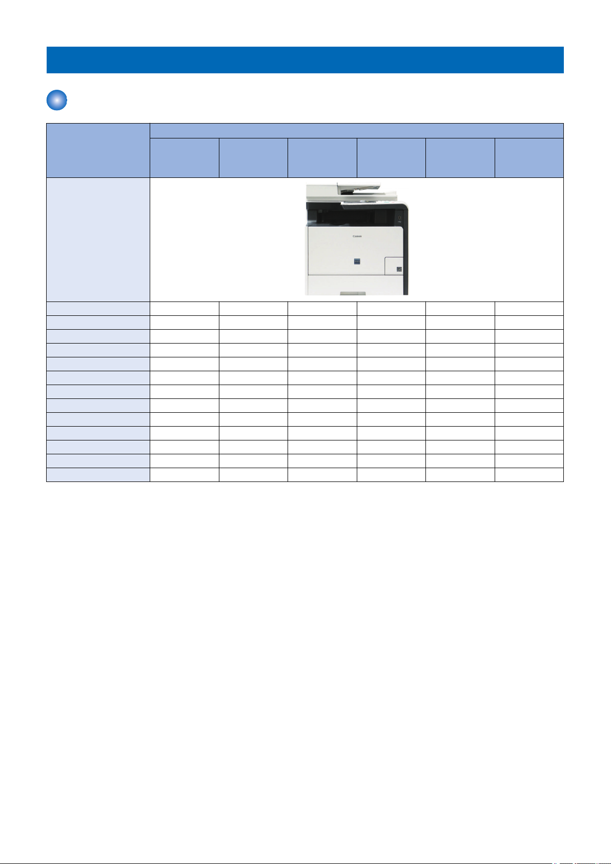
Host Machine
Function MF720 Series (COUNTRY / REGION)
MF728Cdw
(EUR)
Appearance
Copy Yes Yes Yes Yes Yes Yes
Print Yes Yes Yes Yes Yes Yes
Fax Yes Yes Yes Yes No No
USB Scan Yes Yes Yes Yes Yes Yes
Network Scan Yes Yes Yes Yes Yes Yes
Wireless LAN Yes Yes Yes No Yes Yes
Direct Mode Yes Yes Yes No Yes Yes
NFC No Yes Yes No No No
SEND Yes Yes Yes Yes Yes Yes
Sequre Print Yes Yes Yes Yes Yes Yes
Remote UI Yes Yes Yes Yes Yes Yes
ADF (2-side) Yes Yes Yes Yes Yes Yes
Automatic 2-sided Print Yes Yes Yes Yes Yes Yes
MF727Cdw
(CHN, KOR)
MF726Cdw
(USA/CND/
LTN, JP)
MF725Cdn
(CHN)
MF724Cdw
(EUR)
MF722Cdw
(JP)
5
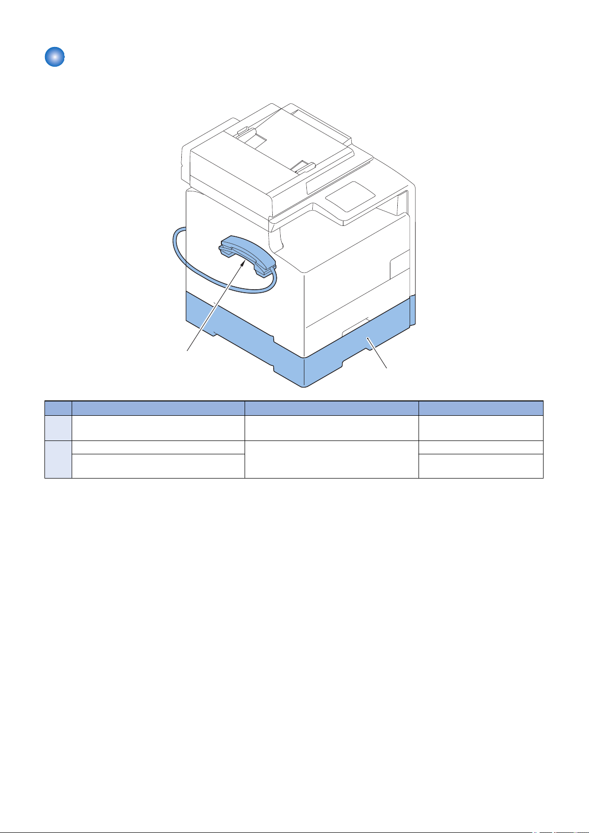
Options
[2]
[1]
■ Hardware Products
1. Product Overview
No. Name Description Remarks
1 Cassette Feeding Module-V1 Expansion of the number of sheets picked up:
250 sheets (60 to 90 g/m2)
2 TELEPHONE 6 KIT Long cord Cool White Addition of phone MF728Cdw
HANDSET KIT 3 Long cord Cool White Standard: MF727Cdw (CHN) /
MF725Cdn
6

434 mm
478.5 mm
1. Product Overview
Product Features
Features
■ Compact Size MFP
A compact body size for A4 color laser MFP has been realized.
■ Improved Control Panel operability
A 3.5-inch color Touch Panel is installed. Support for touch and flick has realized the operability like a smartphone.
In addition, reducing the hard keys and changing them to icons in the display have realized the UI that allows for easy
customization while maintaining the level of operability.
■ Direct Mode supported (supported models only)
Direct communication between the host machine and smartphone, tablet, PC, etc. has been realized.
■ Mobile print supported (Apple Air Print, Google Cloud Print)
Mobile print that enables printing from smartphone, tablet, PC, etc. via an application such as Google DocsTM and GmailTM has
been realized.
■ Wireless LAN supported (supported models only)
Connection between the host machine and PC by wireless communication (radio wave) via wireless LAN router has been realized.
7
1. Product Overview
Specifications
Specifications of Host Machine
Item Specification / Function
Copyboard Fixed
Device Installation Desktop
Light source LED (RGB)
Photoreceptor OPC drum (φ24)
Image scanning CIS (color)
Light exposure method Laser beam exposure
Charging method Roller charging
Developing method Contact development
Transfer method Primary transfer: Sequential 4 colors transfer to Intermediate Transfer Belt
Secondary transfer: 4-color batch transfer onto the transfer material by the Transfer Roller
Separation method Curvature separation
Cassette paper feed Simple separation retard
MP Tray paper feed Pad separation method
Drum cleaning method Cleaning blade
Transfer cleaning method Cleaning brush and roller
Fixing method On-demand fixing
Paper delivery method Face-down
Toner level sensor Mounted
Toner type Non-magnetic one-component toner
Toner supply method All-in-one cartridge (drum + toner)
Toner save mode N/A
Document types Sheet / book
Maximum document size Copyboard Glass: 216 mm × 297 mm
Feeder: 216 mm × 356 mm
Document size sensor N/A
Image size magnification AB series: 25.0%, 50.0%, 70.7%, 81.6%, 86.5%, 100.0%, 115.4%, 122.4%, 141.4%, 200.0%, 400.0%
INCH series: 25.0%, 50.0%, 64.7%, 78.5%, 100.0%, 129.4%, 200.0%, 400.0%
A series: 25.0%, 50.0%, 70.7%, 100.0%, 141.4%, 200.0%, 400.0%
AB/INCH series: 25.0%, 50.0%, 70.7%, 81.6%, 86.5%, 100.0%, 115.4%, 122.4%, 141.4%, 200.0%,
400.0%
Zoom: 25 to 400% (1% increment)
Warm-up Time *1 About 20 seconds or less
Print area Cassette For print jobs (Non-envelope):
• Leading edge: 5.0 +/- 2.0 mm
• Left Side: 5.0 +/- 1.5 mm
For print jobs (envelope):
• Leading edge: 10.0 +/- 2.0 mm
• Left Side: 10.0 +/- 1.5 mm
For copy jobs:
• Leading edge: 5.0 +/- 2.0 mm
• Left Side: 5.0 +/- 1.5 mm
FAX / Report:
• Leading edge: 5.0 +/- 2.0 mm
• Left Side: 5.0 +/- 1.5 mm
8

1. Product Overview
Item Specification / Function
Print area
Reading resolution Color: 600 x 600 dpi, 300 x 600 dpi, 300 x 300 dpi
Reading Speed Fixed (A4/LTR):
Copy resolution 600 x 600 dpi
Print resolution 600 x 600 dpi
First copy time Fixed (A4/LTR):
First print time Color / B&W: 14.5 seconds or less (A4/LTR)
Print Speed 1-sided print (A4/LTR):
Available paper type for cassette
Available paper type for MP
Tray
Available paper size in cassette
MP Tray paper size A4, B5, A5, LGL, LTR, STMT, EXEC, OFFICIO, B-OFFICIO, M-OFFICIO, GLTR, GLGL, FLS, AFLS,
Cassette capacity
MP Tray capacity
Delivery tray stacking capacity
*2
Continuous copying 1 to 99 sheets
Automatic 2-sided Available (A4, B5, LGL, LTR, EXEC, FLS)
Memory capacity 1 GB
Sleep mode Available
Allowable environmental temperature
Allowable humidity 20 to 80% in relative humidity (no condensation)
MP Tray (Non-envelope)
For print jobs:
• Leading edge: 5.0 +/- 2.0 mm
• Left Side: 5.0 +/- 1.5 mm
For copy jobs:
• Leading edge: 5.0 +/- 2.0 mm
• Left Side: 5.0 +/- 1.5 mm
FAX / Report:
• Leading edge: 5.0 +/- 2.0 mm
• Left Side: 5.0 +/- 1.5 mm
(envelope)
For print jobs / For copy jobs:
• Leading edge: 10.0 +/- 2.5 mm
• Left Side: 10.0 +/- 2.5 mm
B&W: 600 x 600 dpi, 300 x 600 dpi
• N/A
Continuous reading, SEND:
• Color: 10 images / minute (A4/LTR)
• B&W: 20 images / minute (A4)
• B&W: 21 images / minute (LTR)
• Color: 16.2 seconds or less
• B&W: 15.5 seconds or less
Continuous reading (A4/LTR):
• Color: 16.7 seconds or less
• B&W: 16.4 seconds or less
• Color / B&W: 20 ppm
2-sided print (A4/LTR):
• Color / B&W: 10 ppm
Plain paper, Recycled paper, Color paper, Thick paper, Coated paper, Label, Postcard, Envelope
(Refer to “Paper types / Paper size” on page 13)
Plain paper, Recycled paper, Color paper, Thick paper, Coated paper, Transparency, Label, Postcard,
Envelope
(Refer to “Paper types / Paper size” on page 13)
A4, B5, A5, LGL, LTR, STMT, EXEC, OFFICIO, B-OFFICIO, M-OFFICIO, GLTR, GLGL, FLS, AFLS,
indLGL, K16, Postcard, Reply Postcard, Envelopes (COM10, Monarch, Nagagata 3, Yougatanaga 3,
C5, DL), Custom Paper Size
(Refer to “Paper types / Paper size” on page 13)
indLGL, K16, Postcard, Reply Postcard, Envelopes (COM10, Monarch, Nagagata 3, Yougatanaga 3,
C5, DL), Custom Paper Size
(Refer to “Paper types / Paper size” on page 13)
Cassette: 250 sheets (60 to 90 g/m2)
Option: 250 sheets (60 to 90 g/m2)
50 sheets (60 to 90 g/m2)
125 sheets (60 to 90 g/m2)
10 to 30 deg C
9
1. Product Overview
Item Specification / Function
Operational noise At stand-by:
• 43 dB or lower (acoustic power level)
During copy jobs:
• Color: 67 dB or lower
• B&W: 66 dB or lower
Power rating Rated input voltage: 100 V (100 V system), 120 to 127 V (120 V system), 220 to 240 V (200 V system)
Rated input frequency: 50/60 Hz
Maximum power consumption 100 V / 120 V / 230 V: 1200 W or lower
Average power at operation 100 V / 120 V / 230 V: 550 W or lower
Average power at standby 100 V / 120 V: 23 W
230 V: 25 W
Average power at sleep mode 100 V / 120 V / 230 V: 1 W (wired) / 2 W (wireless)
Power consumption at Main
Power Switch OFF
Ozone emission Color: 3.0 mg/h
Dimensions (W x D x H) ADF model: 434 × 484 × 478.5 mm
Weight Device (including toner cartridges): Approx. 31 kg
Accessories Refer to “Options” on page 6
0.5 W or lower
B&W: 1.5 mg/h
ADF model (with the optional cassette): 434 × 484 × 578.5 mm
Optional cassette: Approx. 4 kg
*1 : Warm-up time is an interval between when the machine is turned ON and when the main screen appears on the display.
Warm-up time may vary depending on the use conditions and environment of the machine.
*2 : The actual stack capacity varies depending on the site environment and the type of paper used.
ADF Specifications
Item Specification / Function
Document setting direction Set the document face up (face-up method)
Document setting position Center reference
Document processing mode 1-sided document: 1-sided copy/2-sided copy
2-sided document: 1-sided copy/2-sided copy
Document scanning Continuous reading
Loadable sheets
Mixed paper reading Copyboard Glass: 216 mm × 297 mm
Mixed paper Available
Document AE sensor N/A
Document size sensor N/A
Stamp function N/A
Allowable environment Same as device
A4/LTR: 50 sheets (80 g/m2), LGL: 30 sheets (80 g/m2)
Feeder: 216 mm × 356 mm
Wireless LAN Specifications
Item Specification / Function
Standard IEEE 802.11g / IEEE 802.11b / IEEE 802.11n *
Transmission Scheme DS-SS System / OFDM System
Frequency Range 2412 to 2472 MHz
10

Item Specification / Function
Data Transmission Rate IEEE 802.11g:
• 6 / 9 / 12 / 18 / 24 / 36 / 48 / 54 Mbps
IEEE 802.11b:
• 1/2/5.5/11 Mbps
IEEE 802.11n:
• SGI Invalidated 20 MHz : 6.5 / 13 / 19.5 / 26 / 39 / 52 / 58.5 / 65 Mbps
• SGI Validated 20 MHz : 7.2 / 14.4 / 21.7 / 28.9 / 43.3 / 57.8 / 72.2 Mbps
• SGI Invalidated 40 MHz : 13.5 / 27 / 40.5 / 81 / 108 / 121.5 / 135 Mbps
• SGI Validated 40 MHz : 15 / 30 / 45 / 60 / 90 / 120 / 150 Mbps
Communication Mode • Infrastructure Mode
• Direct Mode
Security WEP, WPA-PSK (TKIP/AES-CCMP), WPA2-PSK (TKIP/AES-CCMP)
*: WPS (Wi-Fi Protected Setup), Connection can be established by manually setting values.
SEND Specifications
Item Specification / Function
File Server Transmission E-mail Sending IFAX
Reception Transmission
Communication Protocol
Data Format
System
Environment
Interface 100BASE-TX, 10BASE-T
Inputted
Image
Color
Mode
Paper Size AB configuration: A4, A5, B5
SMB (TCP/IP) , FTP SMTP
PDF, PDF (Compact), PDF(Compact/OCR),
PDF(OCR), JPEG, TIFF
• Windows XP / Vista / 7 / 8 / Server 2003 /
Server 2008 / Server 2012
• Solaris Version 2.6 or later
• Mac OS X
(Mac OS X 10.7 and 10.8 are not supported.)
• Red Hat Linux 7.2 or later
Text, Text / Photo, Photo
Color, Black/White
Inch configuration: Legal (LGL), Letter (LTR), Statement (STMT)
PDF, PDF (Compact),
PDF(Compact/OCR),
PDF(OCR), JPEG, TIFF
• Windows XP / Vista / 7 / 8 / Server 2003 / Server 2008 / Server 2012
• Solaris Version 2.6 or later
• Mac OS X
• Red Hat Linux 7.2 or later
TIFF (BW) JPEG, TIFF (Profile-S,
1. Product Overview
Profile-F)
*1: Size of recording paper at I-Fax reception is A4 size or larger.
11

FAX Specifications
Item Specification / Function
Suitable line Public Switched Telephone Network (PSTN) *
Telephone line connection: 1
Communication Protocol Super G3, G3
Modulation method Image modulation: V.34 / V.17 / V.29 / V.27ter
Transmission procedure: V.21
Transmission speed 33,600 bps
Compression method JBIG, MMR, MR, MH
Error correction method ECM
Minimum receivable input level V.17 / V.27ter / V.29:
• -6 to -43 dBm
V.34:
• 24.0 k to 28.8 k bps: -43 dBm
• 28.8 k to 33.6 k bps: -38 dBm
• 33.6 k bps: -9 dBm
Modem IC SiliconLabs Si2435
Scanning line density Normal: 200 x 100 dpi
Fine: 200 x 200 dpi
Photo: 200 x 200 dpi
Super fine: 200 x 400 dpi
Ultra fine: 400 x 400 dpi
Half tone 256 tones
Receivable reduction setting Automatic reduction: 75-100% (1% increment)
FAX/TEL switching Available
Answering machine transfer setting Available
Remote reception Available
Auto-dialing Available
Delayed transmission N/A
Broadcast transmission Destinations: up to 210
Dual access Up to 10 schedules
Image data backup Available
1. Product Overview
*: Up to 33.6Kbps in modem speed is currently available in PSTN. Note that available modem speed is telephone-line dependent.
12

Paper types / Paper size
1. Product Overview
Type Size Width di-
rection
(mm)
Recycled paper (60 to 74 g/m2)
Color paper (60 to 74 g/m2)
Plain paper 1 (60 to 74 g/m2)
Plain paper 2 (70 to 84 g/m2)
Plain paper 3 (75 to 90 g/m2)
Thick paper 1 (86 to 119 g/m2)
Thick paper 2 (120 to 128 g/m2)
Thick paper 3 (129 to 163 g/m2)
Coated paper 1 (100 to 110 g/m2)
Coated paper 2 (120 to 130 g/m2)
Coated paper 3 (155 to 165 g/m2)
Coated paper 4 (210 to 220 g/m2)
Transparency *1 A4 210.0 297.0 Yes No
Label A4 210.0 297.0 Yes Yes
Postcard Postcard 100 148 Yes Yes
Envelopes Envelopes COM10 104.7 241.3 Yes Yes
A4 *2 210.0 297.0 Yes Yes
B5 182.0 257.0 Yes Yes
A5 148.0 210.0 Yes Yes
LGL 215.9 355.6 Yes Yes
LTR *2 215.9 279.4 Yes Yes
STMT 139.7 215.9 Yes Yes
EXEC 184.1 266.7 Yes Yes
OFFICIO 215.9 317.5 Yes Yes
B-OFFICIO 215.9 355.0 Yes Yes
M-OFFICIO 215.9 341.0 Yes Yes
GLTR 203.2 266.7 Yes Yes
GLGL 203.2 330.2 Yes Yes
FLS 215.9 330.2 Yes Yes
AFLS 206.0 338.0 Yes Yes
indLGL 215.0 345.0 Yes Yes
K16 195.0 270.0 Yes Yes
Custom Paper Size - Yes *3 Yes *4
A4 210.0 297.0 Yes Yes
LTR 215.9 279.4 Yes Yes
A4 210.0 297.0 Yes No
LTR 215.9 279.4 Yes No
LTR 215.9 279.4 Yes No
LTR 215.9 279.4 Yes Yes
Custom Paper Size - Yes *3 Yes *4
Reply Postcard 148 200 Yes Yes
Envelopes Monarch 98.4 190.5 Yes No
Envelopes Nagagata 3 120 235 Yes Yes
Envelopes Yougatanaga
3
Envelopes C5 162 229 Yes Yes
Envelopes DL 110 220 Yes Yes
Custom Paper Size - Yes *3 Yes *4
120 235 Yes Yes
Feeding
direction
(mm)
Pickup position
MP Tray Cassette
*1: Use transparency sheets for laser printers. (Canon’s genuine transparency sheets are specially recommended.)
*2: Fax-received documents or reports can be printed. (excluding heavy paper)
*3: Paper of the following custom paper sizes can be loaded.
• Width 3" to 8 1/2" (76.2 to 215.9 mm); Length 5" to 14"(127 to 355.6 mm)
*4: Paper of the following custom paper sizes can be loaded.
• Width 4" to 8 1/2" (100 to 215.9 mm); Length 5 7/8" to 14" (148 to 355.6 mm)
13
Name of Parts
1
4
6
5
3
2
9
10
8
11
14
13
12
8
7
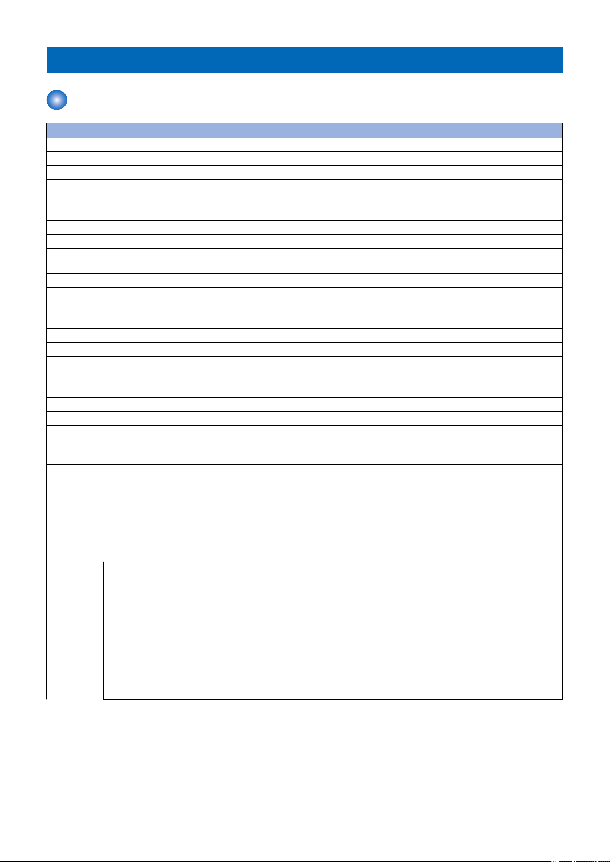
External View
■ Front Side
1. Product Overview
No. Name No. Name
1 Feeder 8 Grip
2 Control panel 9 Paper scanner for document from feeder
3 Front cover 10 Delivery tray
4 Paper cassette 11 Manual feed guide
5 Main power switch 12 Copyboard glass
6 Vent-hole 13 USB memory port
7 Speaker 14 Multi-purpose tray (MP tray)
14
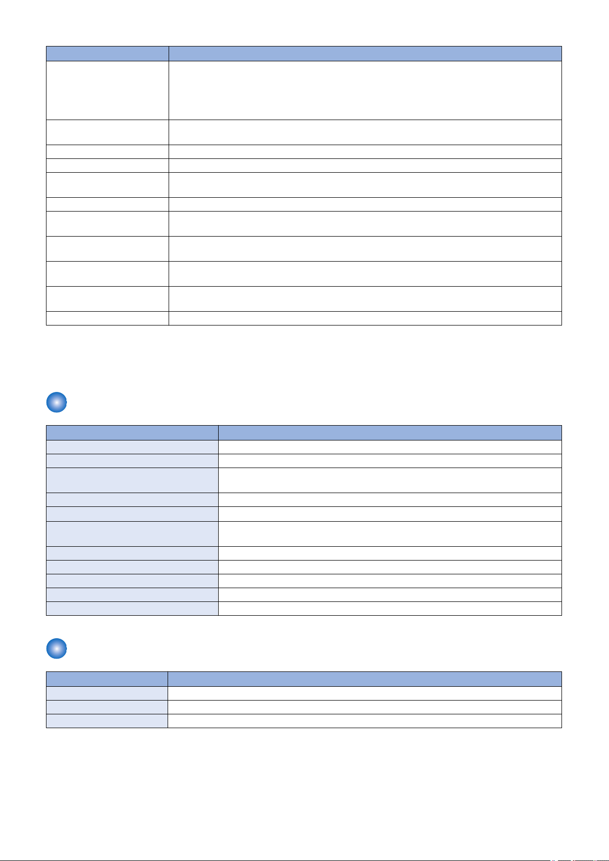
■ Rear Side
3
1
2
4 5 6
7
8
9
10
4
3
2
1
5
No. Name No. Name
1 USB port 6 Handset terminal
2 LAN port 7 Rear cover
3 USB port 8 Rating plate
4 Telephone line terminal 9 Vent-hole
5 External telephone terminal 10 Power socket
1. Product Overview
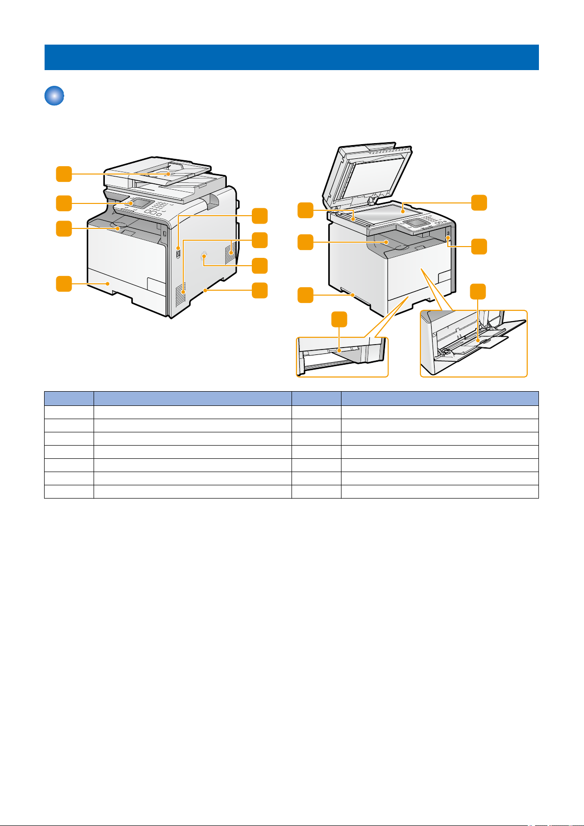
■ Inside
No. Name
1 Y toner cartridge slot
2 M toner cartridge slot
3 C toner cartridge slot
4 Bk toner cartridge slot
5 Toner cartridge tray
15
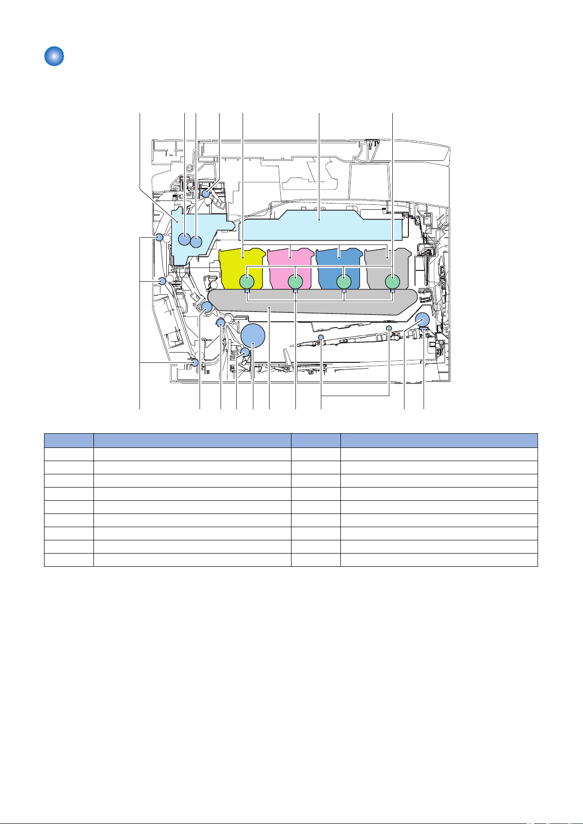
Cross Section View
[1] [2]
[3]
[4]
[5] [6] [7]
[8][9]
[10][11][12][13]
[14][15][16][17]
■ Host Machine
1. Product Overview
No. Name No. Name
1 Fixing assembly 10 MP tray feed roller
2 Pressure roller 11 Primary transfer pad
3 Fixing film unit 12 ITB unit
4 Delivery roller 13 Cassette pickup roller
5 Toner cartridge 14 Cassette separation roller
6 Laser scanner unit 15 Registration roller
7 Photosensitive drum 16 Secondary transfer external roller
8 MP tray separation pad 17 Duplex feed roller
9 MP tray pickup roller
16
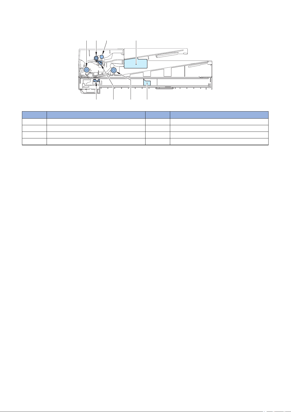
■ Reader / ADF Unit
[1] [2] [3] [4]
[5][6][7]
[8]
No. Name No. Name
1 ADF registration roller 5 Reader unit
2 ADF separation roller 6 ADF delivery roller
3 ADF pickup roller 7 ADF separation pad
4 ADF unit 8 CIS unit
1. Product Overview
17
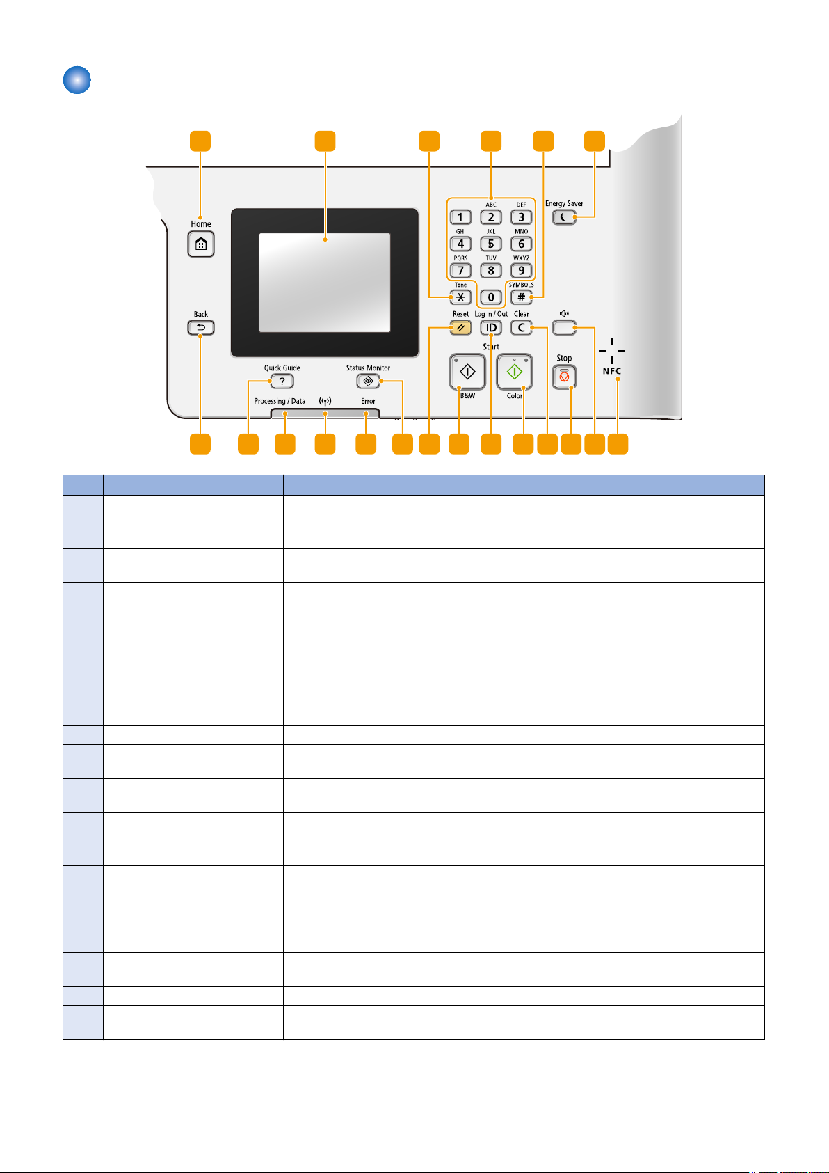
Control Panel
1 2
151617181920
3
4
5
6
78
9101112
1314
1. Product Overview
No. Name Explanation
1 [Home] key Press to display the <Home> Screen.
2 Display You can view the progress of copy, fax, and other jobs and error statuses. The display is a
touch panel, allowing you to operate the screen by touch to specify settings.
3 [*] key • Press to switch the type of text that is entered.
• Press to use tone dialing such as when receiving fax information services.
4 Numeric keys ([0]-[9] keys) Press to enter numbers and text.
5 [#] key Press to enter symbols such as "@" or "/".
6 [Energy Saver] key Press to put the machine into sleep mode. The key lights up green when the machine is in
sleep mode. Press the key again to exit sleep mode.
7 NFC (Near Field Communication)
mark *1
8 [Sound Volume] key Press to adjust volume.
9 [Stop] key Press to cancel copying, faxing, and other operations.
10 [Clear] key Press to delete the entered numbers and text.
11 [Start] (Color) key Press to scan or copy documents in color. In addition, if you press this key when you start
12 [ID] key Press after entering the ID and PIN to log on when Department ID Management is enabled.
13 [Start] (B&W) key Press to scan or copy documents in black and white. In addition, if you press this key when
14 [Reset] key Press to cancel the settings and restore the previously specified settings.
15 [Status Monitor] key Press to check the status of printing or faxing, to view the usage history, or to view the network
16 [Error] indicator Blinks or lights up when an error such as a paper jam occurs.
17 Wi-Fi indicator *2 Lights up when the machine is connected to wireless LAN.
18 [Processing/Data] indicator Blinks while operations such as sending or printing are being performed. Lights up when
19 [Quick Guide] key Press to view operation guidance and error causes/solutions.
20 [Back] key Press to return to the previous screen. If you press this key when specifying settings, for
Pass an NFC-enabled smartphone,etc. with a Canon NFC-compliant application installed on
it over this mark to perform printing and other operations.
printing images from a USB memory device, printouts are printed in color.
After you finish using the machine, press this key again to log off.
you start printing images from a USB memory device, printouts are printed in black and white.
settings such as the IP address of the machine. You can also check the status of the machine,
such as the remaining amounts of paper and toner, or whether any errors occurred.
there are documents waiting to be processed.
example, the settings are not applied and the display returns to the previous screen.
*1 : Models supporting NFC only
*2 : Models supporting wireless LAN only
18

Technical
2
Explanation
Basic Configuration.............................20
Document Exposure/Feeder System
.........................................................22
Controller System................................26
Laser Control System..........................29
Image Formation System....................30
Fixing System......................................41
Pickup / Feed System......................... 44
Embedded RDS.................................. 48
Setting Information Export/Import
Function (DCM)............................... 58
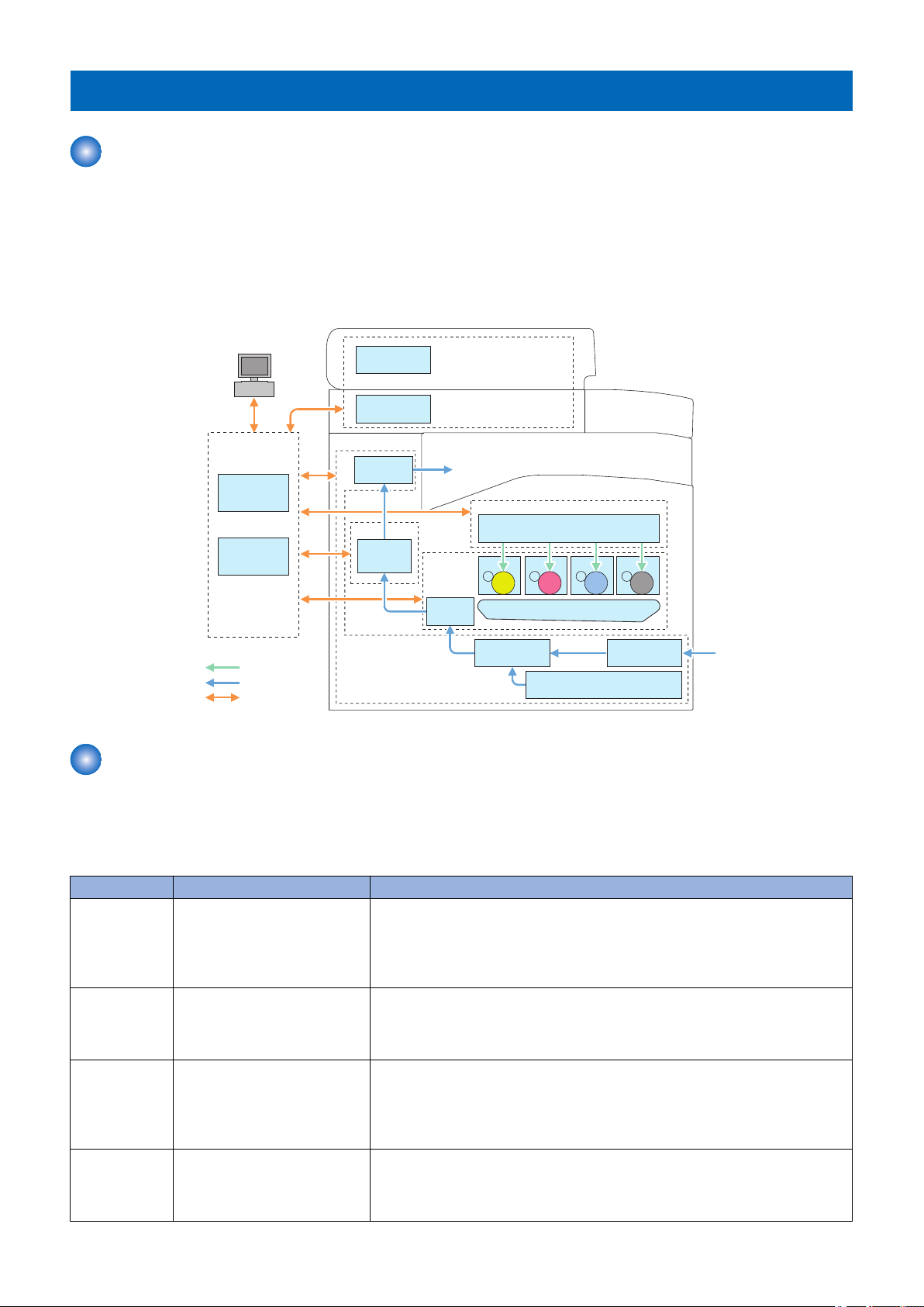
Basic Configuration
Laser Scanner
Laser Exposure System
Main
Controller
DC
Controller
Controller System
Laser beam
㻼㼍㼜㼑㼞㻌㼒㼘㼛㼣
Signal flow
ITB Unit
Secondary
Transfer
Image
Formation
System
Cassette
Manual Feed
Pickup Unit
Pickup
Unit
Pickup/feed System
Fixing
Assembly
Fixing System
Delivery
Assembly
CIS Unit
PC
ADF
Document Exposure/
Feeding System
Drum Drum Drum Drum
Configuration function
This device is roughly composed of the 6 functional blocks as shown in the figure below
• Document exposure/delivery system
• Controller system
• Laser exposure system
• Image formation system
• Fixing system
• Pickup / Feed System
2. Technical Explanation
■ Basic Operational Sequence
The CPU on the DC controller PCB controls the operational sequence. The table below shows the operation and the purposes
in each status from start-up of the device and to last rotation after print job completion.
WAIT
(Wait)
STBY
(STBY)
INTR
(IINTR)
PRINT
(Print)
Basic Sequence
Section Outline Operation
Interval from power-ON or reactivation from sleep mode upon
shutting the door(s) to entering
the print-ready status
Interval from the wait time or the
last rotation to issuance of a print
command from the main controller or power-OFF.
Interval from issuance of a print
command from the main controller during the stand-by status to
warming up the fixing assembly
to the target temperature.
Interval from the initial rotation to
completion of last page fixation.
Activate the printer to be ready for printing. During WAIT time, the following operations are done: pressure is applied to the pressure roller of the fixing assembly;
check cartridges and units being in place; move the developing unit to the home
position; and, clean the ITB. When needed, color displacement is corrected and the
image is stabilized.
Maintain the print-ready status. The printer enters the sleep mode upon receiving
a “sleep” command from the main controller during the stand-by status. The printer
executes color displacement correction or image stabilization upon receiving corresponding commands from the main controller.
To make the printer ready for print jobs, activate high-voltage bias PCBs, the laser
scanner unit and the fixing assembly.
Based on the video signals input from the main controller, form the static latent
image on the photosensitive drum to transfer and fix the toner image on paper.
When a certain pages are printed after power-ON, the device undergoes color displacement correction and/or image stabilization.
20

Section Outline Operation
LSTR
(Last rotation)
Interval from print job completion
to motor deactivation.
The last page of the print job is completely delivered. In this status, the laser scanner
unit and high-voltage bias PCBs are inactive. The printer starts the initial rotation
upon receiving a print command from the main controller during this status.
■ Print Sequence
See "Appendix" > "Print Sequence" in this manual.
■ Print Mode
The models of this series switch among 3 print modes to optimize the paper feed speed for printing.
2. Technical Explanation
Print mode Paper feed
speed
Normal speed
1/1 speed
mode
1/2 speed mode 1/2 speed
1/3 speed mode 1/3 speed
Paper type Print speed Remarks
Plain paper 1 (60 to 74 g/m2)
Plain paper 2 (70 to 84 g/m2)
Plain paper 3 (75 to 90 g/m2)
Recycled paper (60 to 74 g/m2)
Color paper (60 to 74 g/m2)
Thick paper 1 (86 to 119 g/m2)*
1
Thick paper 2 (120 to 128 g/m2)*
Coated paper 1 (100 to 110 g/m2)*
Thick paper 1 (91 to128 g/m2)*
1
Thick paper 2 (120 to 128 g/m2)*
Thick paper 3 (129 to163 g/m2)*
3
Coated paper 1 (100 to 110 g/m2)*
Postcards*
5
Thick paper 3 (129 to 163 g/m2)*
Coated paper 2 (120 to 130 g/m2)
Coated paper 3 (155 to 165 g/m2)
Coated paper 4 (210 to 220 g/m2)
Transparency
Labels
Postcards*
5
Envelopes
6
20 ppm*
Common to color and B&W
printing
2
4
2
9.7 ppm*
4
2
7.6 ppm*
6
6
*1: For Thick Paper 1 (86 to 119 g/m2), switched to normal mode when environment temperature is 20 deg C and above, and
switched to 1/2 speed mode when the temperature is lower than 20 deg C.
*2: For Thick Paper 2 (120 to 128 g/m2), switched to normal mode when environment temperature is 20 deg C and above, and
switched to 1/2 speed mode when the temperature is lower than 20 deg C.
*3: For Ticick Paper 3 (129 to 163 g/m2), switched to 1/2 speed mode when environment temperature is 20 deg C and above,
and switched to 1/3 speed mode when the temperature is lower than 20 deg C.
*4: For Coated paper 1 (100 to 110 g/m2), switched to normal mode when environment temperature is 20 deg C and above, and
switched to 1/2 speed mode when the temperature is lower than 20 deg C.
*5: For Postcard, switched to 1/2 speed mode when environment temperature is 20 deg C and above, and switched to 1/3 speed
mode when the temperature is lower than 20 deg C.
*6: The fastest print speed in each mode.
21
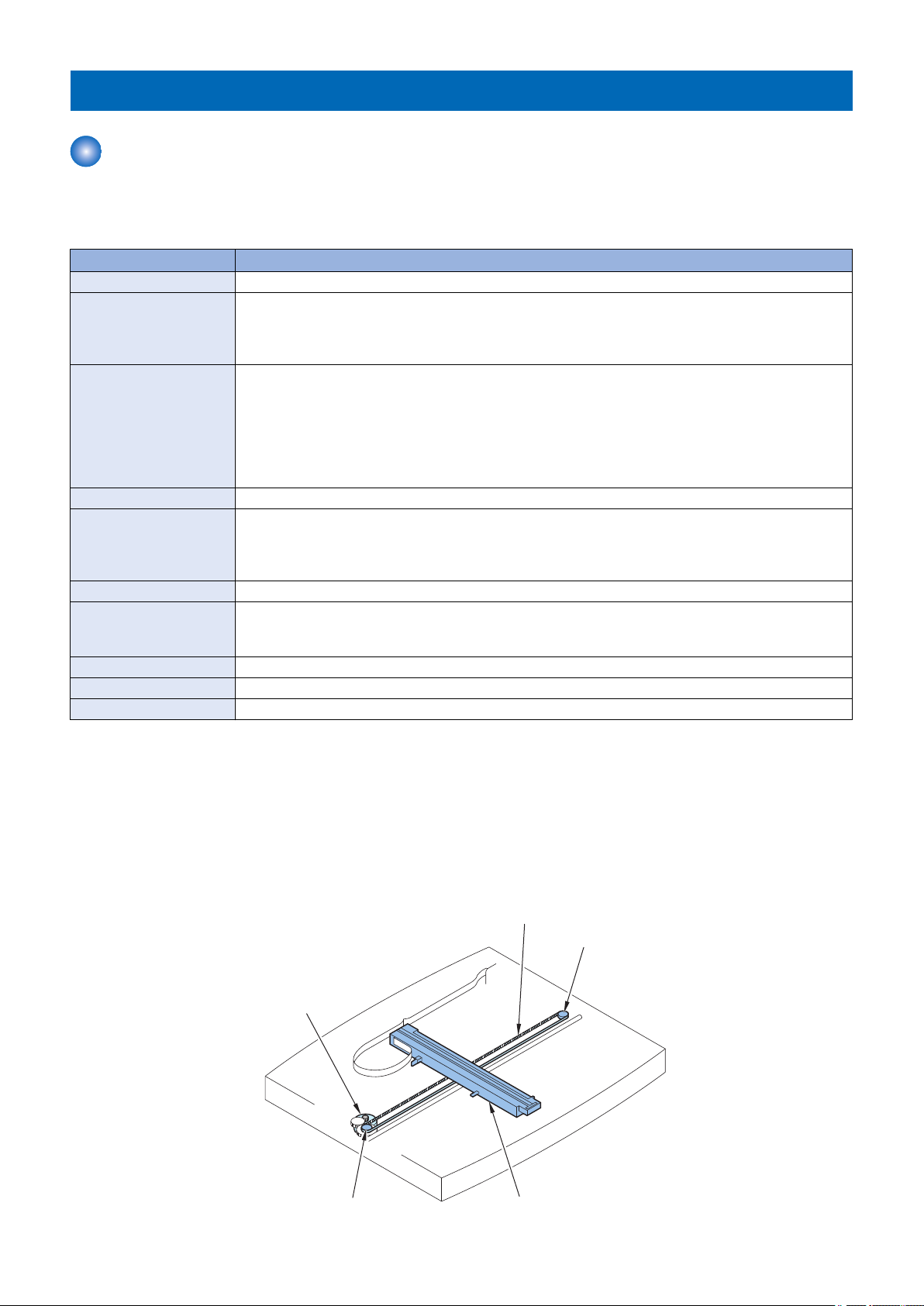
Document Exposure/Feeder System
Drive Belt
Drive Pulley
Drive Pulley
Contact Image Sensor (CIS)
Reader Motor
(M720)
Document Exposure System
■ Overview
Specifications / Control / Function List
Item Function / Method
Document Exposure LED
Document Scan Book Mode:
• Scan by the shift of the contact sensor (CIS)
ADF:
• Document stream reading by fixed contact sensor (CIS)
Scanning Resolution Color:
• 600 dpi (horizontal scanning) x 600 dpi (vertical scanning)
• 300 dpi (horizontal scanning) x 600 dpi (vertical scanning)
• 300 dpi (horizontal scanning) x 300 dpi (vertical scanning)
Black and White:
• 600 dpi (horizontal scanning) x 600 dpi (vertical scanning)
• 300 dpi (horizontal scanning) x 600 dpi (vertical scanning)
Number of Gradations 256 Gradations
Magnification 25% to 400%
Horizontal scanning direction: Image processing by the Main Controller PCB
Vertical scanning direction: The speed at which the carriage moves and image processing by the Main
Controller PCB
Lens CIS/Color
CIS Number of lines: 1 line
Number of pixels: 5184 pixels as total pixels (5107 pixels as effective pixels)
Maximum document scanning width: 216mm
CIS Drive Control Drive Control by Reader Motor (M720)
Document Size Detection None
Dirt Sensor Detection None
2. Technical Explanation
■ Major Components
Followings are the major components for Document Exposure System.
• The contact sensor to scan document.
• The Reader motor (M720), The drive pulley, The drive belt, to shift The contact sensor
In image scanning control, the contact sensor is shifted by rotating the Reader motor based on the drive signal from the Main
Controller PCB and scan the original on the copyboard glass. When ADF is in use, image is scanned by feeding the originals by
ADF instead of shifting the contact sensor.
22
 Loading...