

E
INSTRUCTION
MANUAL

Introduction
The Canon Macro Twin Lite MT-26EX-RT is a flash unit for shooting closeups with Canon EOS cameras, compatible with E-TTL II/E-TTL autoflash
systems. The flash unit is equipped with various functions suitable for a
wide range of shooting objectives, from simple shooting to advanced
shooting. It has functions to control the flash ratio between flash heads A
and B, single-side firing, radio/optical transmission wireless multiple flash
photography using additional slave flash units, and manual flash.
Before Starting to Shoot, Be Sure to Read the Following
To avoid botched pictures and accidents, first read the “Safety
Instructions” (pages 8-9). Also, read this manual carefully to ensure that
you use the product correctly.
Read This Instruction Manual while also Referring to Your
Camera’s Instruction Manual
Before using the product, read this Instruction Manual and your
camera’s Instruction Manual to familiarize yourself with their operations.
Be sure to store this manual safely, too, so that you can refer to it again
when necessary.
Using the MT-26EX-RT with a Camera
Using with an EOS DIGITAL camera (Type-A camera)
You can use the MT-26EX-RT for easy macro flash photography
using autoflash control in the same way as a camera’s built-in flash.
Using with an EOS film camera
An EOS camera with E-TTL II/E-TTL autoflash metering
system (Type-A camera)
You can use the MT-26EX-RT for easy macro flash photography
using autoflash control in the same way as a camera’s built-in flash.
An EOS camera with TTL autoflash metering system (Type-B
camera)
See page 121.
* This Instruction Manual assumes that the MT-26EX-RT is used with a
Typ e -A ca m e ra.
2

Chapters
Introduction
Getting Started with Macro Flash Photography
1
Preparing for macro flash photography and basic shooting operations
Setting Flash Functions with Camera Controls
2
Setting the flash functions from the camera’s menu screen
Radio Transmission Wireless Multiple Flash
3
Photography
Wireless multiple flash shooting by radio transmission
Optical Transmission Wireless Multiple Flash
4
Photography
Wireless multiple flash shooting by optical transmission
Customizing the MT-26EX-RT
5
Customizing with Custom Functions and Personal Functions
Reference
6
System map, troubleshooting guide, using with a type-B camera
2
17
51
57
81
97
107
3

Conventions Used in this Manual
Icons in this Manual
9 : Indicates the Select dial.
8 : Indicates the Select/Set button.
3/1/4/ : Indicates that the respective function remains
7/2 active for approx. 4 sec., 6 sec., 8 sec., 10 sec., or 16
(p.**) : Reference page numbers for more information.
M : M shown on the upper right of the page title indicates
Basic Assumptions
The operation procedures assume that the MT-26EX-RT is attached to
the camera and that both are turned on.
The icons used for buttons, dials, and symbols in the text match the icons
found on the MT-26EX-RT and the camera.
The selection operation performed when setting a function basically
describes selecting a function by turning <9>.
When <?> is displayed at the Function button 4 position, the screen
returns to the previous screen by pressing <?>.
The operation procedures assume that the Custom Functions and
Personal Functions of the MT-26EX-RT, and the menu and Custom
Functions of the camera are at their default settings.
All figures such as the number of flashes are based on the use of four
AA/LR6 alkaline batteries and Canon’s testing standards.
The operation procedures assume that a macro lens is used.
sec. after you let go of the button.
: Warning to prevent shooting problems.
: Supplemental information.
that the function is performed when the camera’s
shooting mode is set to <d/s/f/a/bulb(B)>
(Creative Zone mode).
4

Contents
Introduction 2
Chapters ...........................................................................................3
Conventions Used in this Manual .....................................................4
Index to Features..............................................................................7
Safety Instructions ............................................................................8
Nomenclature..................................................................................10
Getting Started with Macro Flash Photography 17
1
Installing the Batteries.....................................................................18
Attaching and Detaching the Control Unit to and from
the Camera .....................................................................................20
Attaching and Detaching the Flash Unit to the Lens.......................21
Adjusting the Flash Unit..................................................................22
Turning on the Power......................................................................27
a: Fully Automatic Flash Photography ...................................30
E-TTL II/E-TTL Autoflash by Shooting Mode ..................................32
Effective Flash Metering Range......................................................35
D Combined Use with the Diffuser Adapter .................................36
l Setting the Flash Ratio .....................................................38
f Flash Exposure Compensation .................................................40
g FEB...........................................................................................41
7: FE Lock...................................................................................42
c High-speed Sync........................................................................43
r Second-curtain Sync................................................................44
q: Manual Flash.............................................................................45
Clearing MT-26EX-RT Settings ......................................................49
Setting Flash Functions with Camera Controls 51
2
Flash Control from the Camera’s Menu Screen..............................52
5

Contents
Radio Transmission Wireless Multiple Flash Photography
3
' Radio Transmission Wireless Multiple Flash Photography ....... 58
Radio Transmission Wireless Settings........................................... 64
a: Multiple Flash Photography with Slave C Added .............. 69
a: Advanced Multiple Flash Photography with Slaves A, B,
and C Added .................................................................................. 74
q: Multiple Flash Photography with Manual Flash Output ............ 76
[: Shooting in a Different Flash Mode for Each Group ................ 78
Optical Transmission Wireless Multiple Flash Photography
4
:Optical Transmission Wireless Multiple Flash Photography .... 82
Optical Transmission Wireless Settings ......................................... 85
a: Multiple Flash Photography with Slave C Added .............. 88
a: Advanced Multiple Flash Photography with Slaves A, B,
and C Added .................................................................................. 92
q: Wireless Multiple Flash Photography with Manual Flash
Output............................................................................................. 94
Customizing the MT-26EX-RT 97
5
C / >: Setting Custom and Personal Functions................... 98
C: Setting Custom Functions.................................................. 101
>: Setting Personal Functions................................................. 104
Reference 107
6
MT-26EX-RT System ................................................................... 108
f Flash Firing Restrictions due to Temperature Increase ......... 110
Troubleshooting Guide................................................................. 112
Specifications ............................................................................... 116
Using with a Type-B Camera ....................................................... 121
Radio Transmission Wireless Function........................................ 122
Index............................................................................................. 125
57
81
6

Index to Features
Power Source
Batteries Î p.18
Firing interval/count Î p.18
Power ON/OFF Î p.27
Flash ready Î p.27
Quick flash Î p.27
Auto power off Î p.28
Operations
Attaching and detaching
the MT-26EX-RT Î p.20,
p.21
Lock function Î p.28
LCD panel illumination Î p.29
Normal Flash Photography
Full auto (E-TTL) Î p.30
Autoflash by shooting
mode Î p.32
Manual flash Î p.45
Metered manual flash Î p.48
Function
Modeling flash Î p.34
Diffuser adapter Î p.36
Flash exposure
compensation Î p.40
FEB Î p.41
FE lock Î p.42
High-speed sync Î p.43
Second-curtain sync Î p.44
Clearing settings
(Reverting to defaults) Î p.49
Flash function settings Î p.51
Flash firing restriction Î p.110
Typ e-B c am e ra Î p.121
Radio Transmission Wireless
Photography
Remote release Î p.67
Memory function Î p.68
Manual flash Î p.76
Group flash Î p.78
Optical Transmission Wireless
Photography
Memory function Î p.87
Manual flash Î p.94
Customization
Clear all Î p.100
Custom Functions (C.Fn)
Personal Functions (P.Fn)
Î p.101
Î p.104
7

Safety Instructions
Be sure to read these instructions in order to operate the product safely.
Follow these instructions to prevent injury or harm to the operator of the
product or others.
WARNING:
Keep the product out of the reach of young children.
A strap or cord wrapped around a person’s neck may result in strangulation.
The battery is dangerous if swallowed. If swallowed, seek immediate medical
assistance.
Use only power sources specified in this instruction manual for use with the product.
Do not disassemble or modify the product.
Do not expose the product to strong shocks or vibration.
Do not touch any exposed internal parts.
Stop using the product in any case of unusual circumstances such as the presence of
smoke or a strange smell.
Do not use organic solvents such as alcohol, benzine or paint thinner to clean the
product.
Do not get the product wet. Do not insert foreign objects or liquids into the product.
Do not use the product where flammable gases may be present.
This may cause electric shock, explosion or fire.
Observe the following instructions when using commercially available batteries or
provided battery packs.
• Use batteries/battery packs only with their specified product.
• Do not heat batteries or expose them to fire.
• Do not charge batteries/battery packs using non-authorized battery chargers.
• Do not expose the terminals to dirt or let them come into contact with metallic pins or
other metal objects.
• Do not use leaking batteries/battery packs.
• When disposing of batteries/battery packs, insulate the terminals with tape or other
means.
This may cause electric shock, explosion or fire.
If a battery/battery pack leaks and the material contacts your skin or clothing, flush the
exposed area thoroughly with running water. In case of eye contact, flush thoroughly
with copious amounts of clean running water and seek immediate medical assistance.
Do not allow the product to maintain contact with the same area of skin for extended
periods of time during use.
This may result in low-temperature contact burns, including skin redness and blistering,
even if the product does not feel hot. The use of a tripod or similar equipment is
recommended when using the product in hot places and for people with circulation
problems or less sensitive skin.
Denotes the risk of serious injury or death.
8

Safety Instructions
Follow any indications to turn off the product in places where its use is forbidden.
Not doing so may cause other equipment to malfunction due to the effect of
electromagnetic waves and even result in accidents.
To prevent fire, excessive heat, chemical leakage, explosions, and electrical shock,
follow the safeguards below:
• Do not insert the battery’s plus and minus ends incorrectly.
Do not fire the flash at anyone driving a car or other vehicle.
It may cause an accident.
Do not use or store the equipment in dusty or humid places.
This is to prevent fire, excessive heat, electrical shock, and burns.
CAUTION:
Do not fire the flash near the eyes.
It may hurt the eyes.
Flash emits high temperatures when fired. Keep fingers, any other part of your body,
and objects away from the flash unit while taking pictures.
This may cause burns or malfunction of the flash.
Do not leave the product in places exposed to extremely high or low temperatures.
The product may become extremely hot/cold and cause burns or injury when touched.
Do not touch any parts inside the product.
This may cause injury.
When the product is not in use for a prolonged period, make sure to remove the
batteries before storing.
This is to prevent malfunction or corrosion.
Be careful when you replace the batteries after continually firing.
The batteries may be hot and it may cause a skin burn.
Denotes the risk of injury.
9
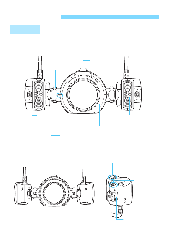
Nomenclature
Flash Unit
Connecting
cord
Focusing lamp
(p.33)
Rotate button
(p.22)
Flash Unit
Hood mount (p.26)
Release button
(p.21, 22)
Flash head B
(p.21, 36)
Flash head mount
(p.21, 22)
Standard position index
(Vertical angle) (p.22)
Flash Unit Rear Flash Head Side & Bottom
Release levers
<a> Indicator
(p.36)
10
Mount ring (p.21, 22)
Filter mounting thread (p.25)
(58 mm dia.)
<b> Indicator
(p.36)
Tripod socket
Flash head A
(p.21, 36)
Diffuser adapter
attachment mount (p.36)
Standard
position index
(Horizontal
angle)
Angle setting
scale
(p.22)
Mounting foot
(Flash unit) (p.21)
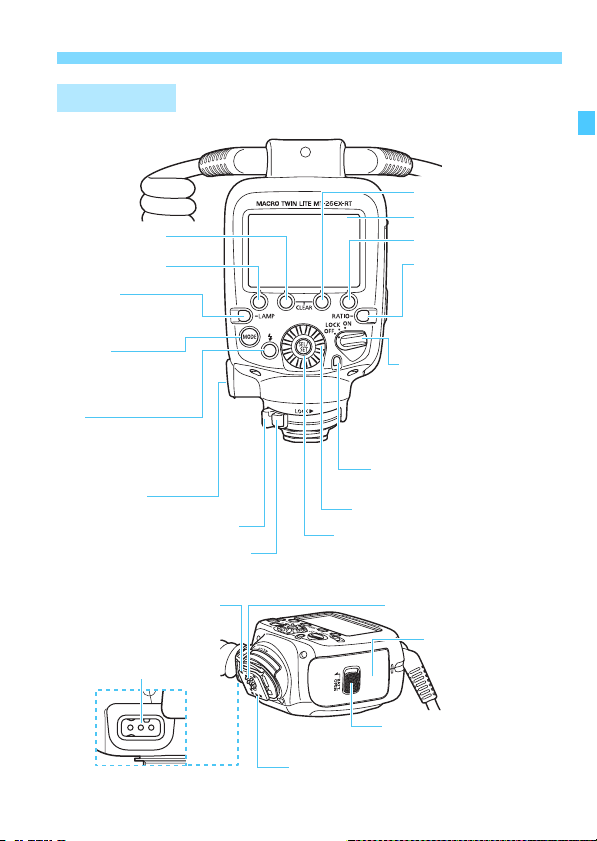
Control Unit
Function button 2
Function button 1
<d>
Focusing lamp button
(p.33)
<E>
Flash mode button
(p.30, 45, 69, 76, 78,
88, 94)
<Q>
Flash-ready lamp/
Test flash button
(p.28, 70, 89, 101, 105,
112 )
Terminal cover
Mounting foot lock lever (p.20)
Lock-release button (p.20)
Function button 3
LCD panel
Function button 4
<,>
Flash ratio setting/
Flash head select button
(p.38, 45, 64, 69, 74, 76,
85, 88, 92, 94)
Power switch (p.27)
<K>:Power on
<a> : Button/Dial lock
<J>:Power off
Flash exposure confirmation
lamp (p.30, 71, 89)
<9> Select Dial
<8> Setting button
Nomenclature
(Power on)
Mounting foot (Control unit)
(p.20)
External power
source terminal
Contacts
Battery compartment cover
lock release lever (p.18)
Mounting foot locking pin
Battery compartment
cover (p.18)
11
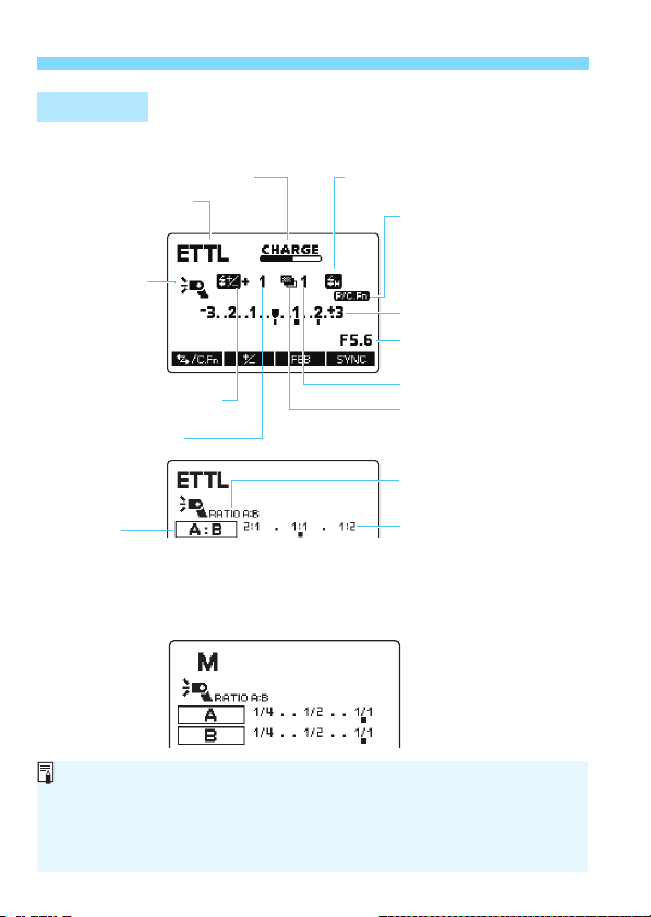
Nomenclature
LCD Panel
E-TTL II/E-TTL Autoflash (p.30)
G : Charge indicator (p.27)
a : E-TTL II/E-TTL
autoflash
Diffuser adapter
(p.36)
E : Attached to A
F : Attached to B
D : Attached to
A, B
f : Flash exposure
compensation (p.40, 55)
Flash exposure
compensation amount
Firing group
l : Fire A:B (flash ratio control)
4 : Fire A (single-side firing)
5 : Fire B (single-side firing)
Manual Flash (p.45)
c : High-speed sync (p.43, 55)
r : Second-curtain sync (p.44, 55)
< : Personal Functions
(p.98, 101)
= : Custom Functions
(p.98, 104)
> : Personal/Custom
Functions
Flash exposure level
Aperture
FEB sequence (p.102)
g : FEB (p.41, 55)
, : Flash ratio setting
(p.38)
Flash ratio
The displays shown are examples. The display will show only the
conditions currently applied.
The functions displayed above function buttons 1 to 4, such as <u>
and <@>, change according to the setting status.
When a button or dial is operated, the LCD panel illuminates (p.29).
12
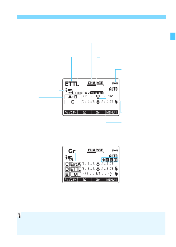
Nomenclature
Radio Transmission Wireless Multiple Flash Photography
(p.57)
Firing group control G : Master unit/Slave unit charge
, : Flash ratio control
Flash mode
a : E-TTL II/E-TTL
autoflash
q : Manual flash
[ : Group flash
g
: Wireless shooting
(master)
Firing group
l: Fire A:B
(flash ratio control)
4:Fire A
5:Fire B
6: Fire C (slave C)
j: Fire A, B, and C
Flash mode for each
group ([ only)
status
k : Sync speed warning
M : Master setting
v : Sub-master status (p.73)
' : Radio transmission
wireless shooting
w: Unconnected
x: Connection error
* : Transmission
channel
): Transmission
channel
automatic setting
Q : Slave flash ready
Flash ratio
Firing group charge
status ([ only)
m : Flash not ready
x : Flash ready
During radio transmission wireless multiple flash shooting, when the master
unit and slave unit are fully charged, <G> disappears. Also, during
<[> flash shooting, when all flash units are fully charged, the “firing group
charge status” indication also disappears.
13
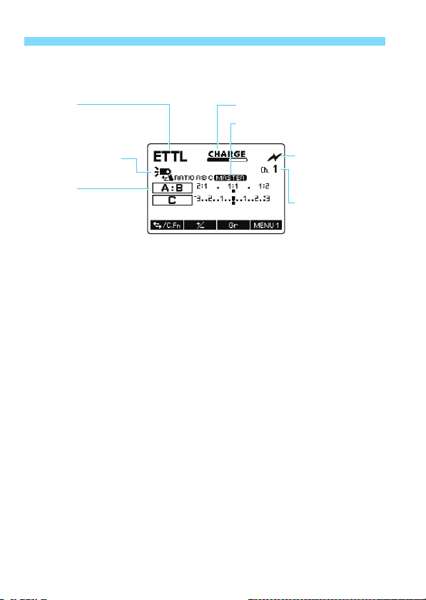
Nomenclature
Optical Transmission Wireless Multiple Flash Photography
(p.81)
Flash mode
a : E-TTL II/E-TTL
autoflash
q : Manual flash
g
: Wireless shooting
(master)
Firing group
l: Fire A:B
(flash ratio control)
4:Fire A
5:Fire B
6: Fire C (slave C)
j: Fire A, B, and C
G : Charge indicator
M : Master setting
:: Optical
transmission
wireless
shooting
* : Transmission
channel
14
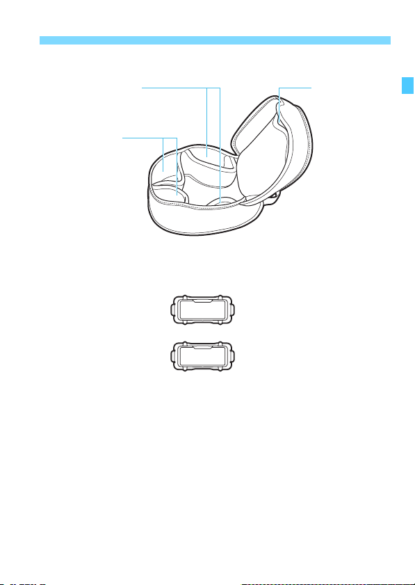
Provided Accessories
Nomenclature
Diffuser adapter pockets
Flash head pockets
Case
Diffuser adapter
SDA-E1
(p.36)
Mount ring pocket
15

16

1
Getting Started with
Macro Flash Photography
This chapter describes the preparations before starting
macro flash photography and the basic shooting
operations.
Cautions for firing continuous flash
To avoid degrading and damaging the flash unit due to
overheating, limit the continuous firing at full output to 20
times or less. After continuously firing the flash 20 times,
allow a rest time of at least 10 min.
If you fire the flash continuously 48 times and then fire the
flash again repeatedly at short intervals, the safety function
may activate and restrict flash firing. With flash firing
restriction, the firing interval is automatically set to approx.
8-20 sec. If this happens, allow a rest time of at least 25 min.
For details, see “Flash Firing Restrictions due to
Temperature Increase” on page 110.
Conditions of the subject greatly influence the exposure when
shooting close-ups. Therefore, it is recommended to shoot the
same subject with different exposures (p.40) and check the
exposure after shooting.
17
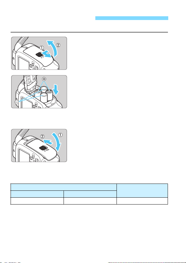
Installing the Batteries
Install four AA/R6 batteries for power supply.
Open the cover.
1
Slide the lock-release lever to the left
as shown in the illustration, slide the
cover down, then open the battery
compartment cover.
Install the batteries.
2
Make sure the “+” and “-” electrical
contacts are correctly oriented as
shown in the battery compartment.
The grooves on the side surfaces of
the battery compartment indicate “-”.
This is convenient when replacing the
batteries in a dark place.
Close the cover.
3
Close the battery compartment cover
and slide it up.
X When it clicks in place, the battery
compartment cover is locked.
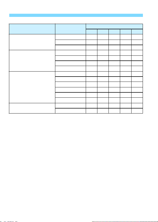
Firing Interval and Number of Flashes
MT-26EX-RT alone
Firing Interval
Quick Flash Normal Flash
Approx. 0.1-3.3 seconds Approx. 0.1 - 5.5 seconds Approx. 100 - 700 times
Based on new AA/LR6 alkaline batteries, both-sides firing, and Canon’s testing
standards.
The Quick flash function enables flash photography before the flash is fully
charged (p.27).
Number of Flashes
18
Installing the Batteries
CAUTION
Do not use “AA/R6 lithium batteries”.
Note that certain “AA/R6 lithium batteries” may become extremely hot in
rare cases during use. Due to safety reasons, do not use “AA/R6 lithium
batteries”.
When performing continuous flash, do not touch the flash unit,
batteries, or the area near the battery compartment.
When continuous flash or modeling flash is repeatedly fired at short
intervals, do not touch the flash unit, batteries, or the area near the battery
compartment. The flash unit, batteries, and area near the battery
compartment may become hot, resulting in the risk of burn.
Do not allow the product to maintain contact with the same area of
skin for extended periods of time during use.
This may result in low-temperature contact burns, including skin redness
and blistering, even if the product does not feel hot. The use of a tripod or
similar equipment is recommended when using the product in hot places
and for people with circulation problems or less sensitive skin.
Using AA/R6 batteries other than the alkaline type may cause contact
failure because their battery contact shapes are not standardized.
When using the Compact Battery Pack CP-E4N (sold separately, p.109),
also refer to the CP-E4N Instruction Manual.
When <!> is displayed or the LCD panel display turns off during
recharging, replace the batteries with new ones.
Use a new set of four batteries of the same brand. When replacing the
batteries, replace all four at one time.
AA/HR6 Ni-MH batteries can also be used.
19
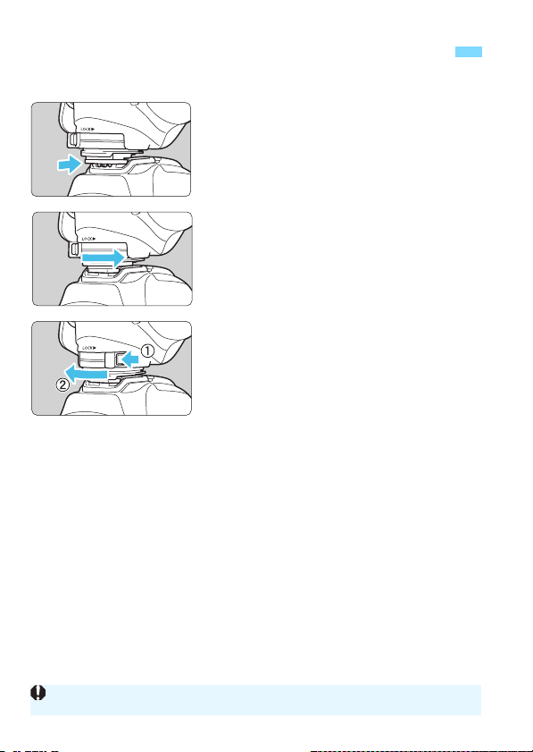
Attaching and Detaching the Control Unit to and from the Camera
Attach the control unit.
1
Slip the control unit’s mounting foot
all the way into the camera’s hot
shoe.
Secure the control unit.
2
Slide the mounting foot lock lever to
the right.
X When the lock lever clicks in place, it
is locked.
Detach the control unit.
3
While pressing the lock-release
button, slide the lock lever to the left
and detach the control unit from the
camera.
Be sure to turn off the MT-26EX-RT before attaching or detaching it.
20
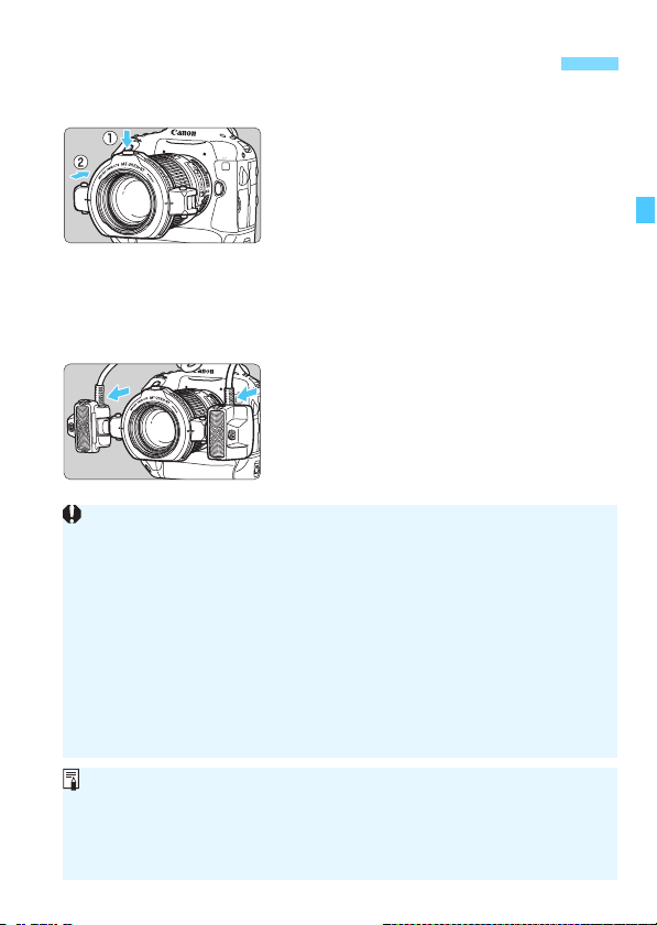
Attaching and Detaching the Flash Unit to the Lens
Attach the flash unit to the front
1
of the lens while holding down
the release button on the mount
ring.
Position the release button toward the
top.
Make sure that the flash unit is
securely attached.
Detach the flash unit while holding
down the release button.
Attach flash heads A and B to
2
flash head mounts.
Push them in to the mounting feet
until they click in place.
To detach the flash heads, press the
release lever (p.10).
Be sure to attach the flash unit to the lens when shooting. Shooting while
holding the flash unit in your hand may result in a low temperature burn.
Do not touch the flash unit or batteries immediately after continuous flash
firing or modeling flash (p.34). Touching them may result in a burn. Make
sure that the flash unit has cooled before detaching the flash unit or
replacing batteries.
To rotate the mount ring, be sure to first hold down the release button.
If the Macrolite Adapter 72C screwed onto the EF180mm f/3.5L Macro
USM lens filter thread becomes stuck and cannot be unscrewed, without
pressing the release button, turn the mount ring against the lens in the
direction you would to detach the adapter.
The flash unit cannot be attached to the EF-M28mm f/3.5 Macro IS STM.
When using the following lenses, attach the Macrolite Adapter (sold
separately) to the front of the lens (filter mounting thread) and then attach
the flash unit.
• EF100mm f/2.8L Macro IS USM: Macrolite Adapter 67
• EF180mm f/3.5L Macro USM: Macrolite Adapter 72C
21

Adjusting the Flash Unit
Flash Unit Adjustment Range
The MT-26EX-RT’s flash unit can be adjusted within the range shown
below to match the lens and subject.
Standard position index
(Horizontal angle)
Angle setting scale
Flash head
Rotate button
Standard position index (Vertical angle)
"To rotate the mount ring, rotate it while holding down the release
button.
#To rotate the flash head mount, rotate it while holding down the
rotate button.
$To rotate the flash head in the direction of %, directly move the
flash head.
Release button
Release button
Do not adjust the flash head angle beyond the adjustable range. Doing so
may cause the flash head to detach and fall from the flash head mount.
The adjustable range may be further limited depending on the camera
and lens.
22
Adjusting the Flash Unit
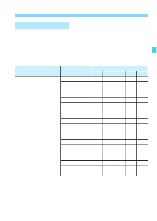
Adjustment Guidelines
This is a general guide to setting the flash angle for various
magnifications with a macro lens. Refer to the angle scale (15°
increments) on the side of the flash head and set the same angle for
both flash heads A and B. The angle specifications in the table below
indicate the inner angle relative to the flash head’s standard position
index (horizontal).
Lens Magnification
EF50mm f/2.5
Compact Macro
EF50mm f/2.5
Compact Macro
+Life-Size
Converter EF
EF100mm f/2.8L
Macro IS USM
EF100mm f/2.8 Macro
USM
EF100mm f/2.8 Macro
1:2
1:2.5 - 1:3
1:4
1:5 - 1:6
1:8
1:10
1:1
1:1.2
1:1.5 - 1:2
1:4
1:1 - 1:1.5
1:2
1:2.5 - 1:3
1:4
1:1
1:1.5
1:2
1:2.5 - 1:3
1:4
Flash Head Inner Angle
60° 45° 30° 15° 0°
23
Adjusting the Flash Unit
Lens Magnification
EF180mm f/3.5L Macro
USM
EF-S35mm f/2.8 Macro IS
STM
EF-S60mm f/2.8 Macro
USM
MP-E65mm f/2.8 1-5x
Macro Photo
* Near the closest focusing distance, the flash unit may touch the subject
depending on the shape or size of the subject. Also, the light from the focusing
lamp may be obstructed.
1:1
1:1.2 - 1:1.5
1:2 - 1:10
1:1*
1:1.4
1:2
1:3.3
1:1
1:1.5
1:2
1:3
1:4
1:5
5x - 2x
1x
Flash Head Inner Angle
60° 45° 30° 15° 0°
24
Adjusting the Flash Unit
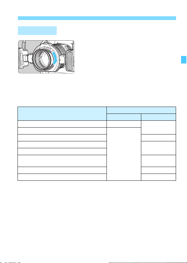
Using a Filter
A commercially-available filter can be
used during flash photography. A filter
can be attached, using the two
procedures described below. Filters may
not be used together with some macro
lenses.
(1) Attach a 58 mm filter to the filter mounting thread of the mount ring
(see the above illustration).
(2) Attach the flash unit to the lens with the filter attached to the front of
the lens (filter mounting thread).
Macro Lens
EF50mm f/2.5 Compact Macro Not usable*
EF100mm f/2.8 Macro
EF100mm f/2.8 Macro USM Not Usable
EF100mm f/2.8L Macro IS USM
EF180mm f/3.5L Macro USM
EF-S35mm f/2.8 Macro IS STM
EF-S60mm f/2.8 Macro USM Usable
MP-E65mm f/2.8 1-5x Macro Photo Not Usable
*1: The lens cannot be used with a filter, since focusing is interrupted by an
attached filter touching the front of the lens. Also, filter may be damaged or the
lens malfunction may result.
*2: Attach a filter to the front of the lens before attaching Macrolite Adapter (p.21) to
the front part of the filter. If attachment threads are not provided on the front rim
of the filter, the flash unit cannot be attached since Macrolite Adapter cannot be
attached. Note that if the flash unit is attached after a filter and Macrolite
Adapter are attached to the front of the lens, the periphery of the photo may
look darker.
*3: Attach the Lens Hood ES-27 to the front of the lens before attaching a 49 mm
filter.
Filter Compatibility
(1) (2)
1
Conditionally
Usable
Conditionally
Usable
usable*
usable*
2
3
25

Adjusting the Flash Unit
Using a Hood
When mounting a dedicated hood (sold separately) to the MP-
E65mm f/2.8 1-5x Macro Photo or mounting the Lens Hood ES-27 to
EF-S35mm f/2.8 Macro IS STM, first attach the hood, then attach the
mount ring. If a hood is attached, a 58 mm filter cannot be attached
to the filter mounting thread of the mount ring.
With the EF100mm f/2.8 Macro USM, the Lens Hood ET-67 can be
attached to the mount ring’s hood mount. Use ambient light for
shooting. Using flash will result in darkened edges.
26

Turning on the Power
Set the power switch to <K>.
1
X The flash recharge starts.
X During recharging, <G> is
displayed on the LCD panel. When
flash recharge is complete, this
indicator disappears.
Check that the flash is ready.
2
The status of the flash-ready lamp
changes from off to green (Quick
flash ready), then to red (fully
charged).
You can press the test flash button
(flash-ready lamp) to fire a test flash.
Quick Flash Function
The Quick flash function enables flash photography when the flashready lamp is lit green (before the flash is fully charged). Quick flash is
available regardless of the camera’s drive mode setting. Although the
flash output will be approx. 1/2 to 1/6 of the full output, it is useful for
shooting with a shorter firing interval.
During manual flash shooting, this function is available when the flash
output is set to 1/4 or smaller. Note that you cannot use Quick flash with
FEB or during wireless multiple flash shooting.
When Quick flash is fired during continuous shooting, underexposure
may occur since the flash output decreases.
Note that the test flash cannot be performed while the camera’s metering
timer, etc. is operating.
For the display of <G> during radio transmission wireless multiple
flash shooting, see page 72.
27

Turning on the Power
Auto Power Off Function
To save battery power, the power will turn off automatically after approx.
90 sec. of idle use. To turn on the MT-26EX-RT again, press the
camera’s shutter button halfway or press the test flash button (flashready lamp).
When set as the master unit for radio transmission wireless multiple
flash shooting (p.58), the time until auto power off takes effect is approx.
5 min.
Lock Function
By setting the power switch to <a>, you can disable the flash’s
button and dial operations. It is useful when you want to prevent the
flash function settings from being accidentally changed after you set
them.
If you operate a button or dial, <k> is displayed on the LCD panel.
While the lock is active, the functions displayed above function buttons
1 to 4, such as <u> and <@>, are not displayed.
28

Turning on the Power
LCD Panel Illumination
When a button or dial is operated, the LCD panel illuminates for approx.
12 sec. (p).
During normal flash photography and radio/optical transmission
wireless multiple flash shooting (p.58/82), the LCD panel illuminates in
green.
For the LCD panel Illumination during radio transmission wireless
multiple flash shooting, see page 72.
The flash settings will remain in effect even after the power is turned off.
To retain the settings when replacing the batteries, replace the batteries
after turning off the power switch.
You can fire a test flash or turn on/off the focusing lamp while the power
switch is set to the <a> position. Also, when a button or dial is
operated, the LCD panel illuminates.
You can disable Quick flash (P.Fn-05, p.105).
Auto power off can be disabled (C.Fn-01, p.101).
You can select the charging method to be used when an external power
source is used (C.Fn-12, p.102).
You can change the setting of the LCD panel illumination (C.Fn-22,
p.103).
You can change the color of the LCD panel illumination (P.Fn-04, p.104).
29
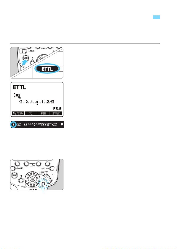
a
When you set the camera’s shooting mode to <d> (Program AE) or
fully automatic mode, you can shoot in E-TTL II/E-TTL fully automatic
flash mode.
: Fully Automatic Flash Photography
Set the flash mode to <a>.
1
Press the <E> button.
Turn <9>, select <Q>, then
press <8>.
Check that <M> is not
displayed.
Focus on the subject.
2
Press the shutter button halfway to
focus.
X The shutter speed and aperture are
displayed in the viewfinder.
Check that <Q> is lit in the viewfinder.
Take the picture.
3
When you press the shutter button
completely, the flash will fire and the
picture will be taken.
X If the standard flash exposure is
Flash exposure
confirmation lamp
obtained, the flash exposure
confirmation lamp lights for approx. 3
sec.
30
 Loading...