

87654321
Service Manual
M3010 Series

Application
This manual has been issued by Canon Inc. for qualied persons to learn technical theory,
installation, maintenance, and repair of products. This manual covers all localities where the
products are sold. For this reason, there may be information in this manual that does not
apply to your locality.
Corrections
This manual may contain technical inaccuracies or typographical errors due to improvements
or changes in products. When changes occur in applicable products or in the contents of this
manual, Canon will release technical information as the need arises. In the event of major
changes in the contents of this manual over a long or short period, Canon will issue a new
edition of this manual.
The following paragraph does not apply to any countries where such provisions are
inconsistent with local law.
Trademarks
The product names and company names used in this manual are the registered trademarks
of the individual companies.
Copyright
This manual is copyrighted with all rights reserved. Under the copyright laws, this manual may
not be copied, reproduced or translated into another language, in whole or in part, without the
consent of Canon Inc.
© CANON INC. 2011
Caution
Use of this manual should be strictly supervised to avoid disclosure of condential
information.
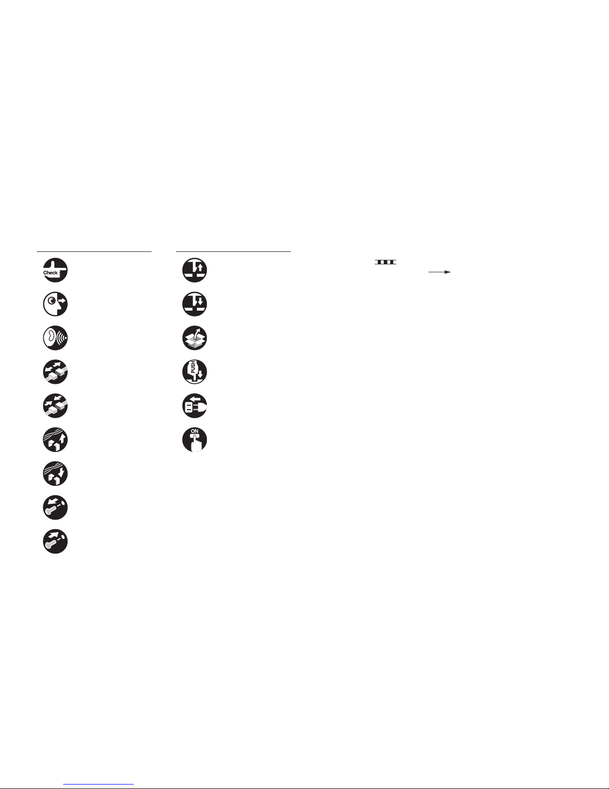
Explanation of Symbols
The following symbols are used throughout this Service Manual.
Symbols Explanation Symbols Explanation
Check. Remove the claw.
Check visually. Insert the claw.
Check the noise. Use the bundled part.
Disconnect the connector. Push the part.
Connect the connector. Plug the power cable.
Remove the cable/wire
from the cable guide or wire
saddle.
Turn on the power.
Set the cable/wire to the
cable guide or wire saddle.
Remove the screw.
Tighten the screw.
The following rules apply throughout this Service Manual:
1. Each chapter contains sections explaining the purpose of specic functions and the
relationship between electrical and mechanical systems with reference to the timing of
operation.
In the diagrams,
represents the path of mechanical drive; where a signal name
accompanies the symbol, the arrow
indicates the direction of the electric signal.
The expression "turn on the power" means ipping on the power switch, closing the front
door, and closing the delivery unit door, which results in supplying the machine with power.
2. In the digital circuits, '1' is used to indicate that the voltage level of a given signal is "High",
while '0' is used to indicate "Low". (The voltage value, however, differs from circuit to
circuit.) In addition, the asterisk (*) as in "DRMD*" indicates that the DRMD signal goes on
when '0'.
In practically all cases, the internal mechanisms of a microprocessor cannot be checked
in the eld. Therefore, the operations of the microprocessors used in the machines are not
discussed: they are explained in terms of from sensors to the input of the DC controller
PCB and from the output of the DC controller PCB to the loads.
The descriptions in this Service Manual are subject to change without notice for product
improvement or other purposes, and major changes will be communicated in the form of
Service Information bulletins.
All service persons are expected to have a good understanding of the contents of this Service
Manual and all relevant Service Information bulletins and be able to identify and isolate faults
in the machine.

Contents
0 Safety Precautions
CDRH Provisions -------------------------------------------------------------0-2
Laser Safety --------------------------------------------------------------------0-2
About Laser Beams --------------------------------------------------------------- 0-2
Handling Laser Scanner Unit --------------------------------------------------- 0-2
Toner Safety --------------------------------------------------------------------0-3
About Toner ------------------------------------------------------------------------- 0-3
Handling Adhered Toner --------------------------------------------------------- 0-3
Notes on Handling Lithium Battery ---------------------------------------0-3
Notes on Assembly/Disassembly ----------------------------------------- 0-3
1 Product Overview
Product Lineup -----------------------------------------------------------------1-2
Host Machine ----------------------------------------------------------------------- 1-2
Options ------------------------------------------------------------------------------- 1-2
Product Features --------------------------------------------------------------1-2
Product Features ------------------------------------------------------------------- 1-2
Specications ------------------------------------------------------------------1-3
Product Specications ------------------------------------------------------------ 1-3
Parts Name ---------------------------------------------------------------------1-4
External View ----------------------------------------------------------------------- 1-4
Front side of the machine----------------------------------------------------------------- 1-4
Rear side of the machine ----------------------------------------------------------------- 1-4
Cross Section View ---------------------------------------------------------------- 1-5
Control Panel ----------------------------------------------------------------------- 1-5
2 Technical Overview
Basic Conguration -----------------------------------------------------------2-2
Conguration function ------------------------------------------------------------ 2-2
Basic Sequence -------------------------------------------------------------------- 2-2
Basic Sequence of Operation ----------------------------------------------------------- 2-2
Print Sequence ------------------------------------------------------------------------------ 2-3
Power-On Sequence----------------------------------------------------------------------- 2-4
Controller System -------------------------------------------------------------2-5
Main Controller --------------------------------------------------------------------- 2-5
Overview -------------------------------------------------------------------------------------- 2-5
Engine Controller ------------------------------------------------------------------ 2-5
General description ------------------------------------------------------------------------ 2-5
Service Works ---------------------------------------------------------------------- 2-6
At parts replacement ----------------------------------------------------------------------- 2-6
Maintenance --------------------------------------------------------------------------------- 2-6
Notes on service works ------------------------------------------------------------------- 2-6
Original Exposure System -------------------------------------------------- 2-7
Overview ----------------------------------------------------------------------------- 2-7
Major Components ---------------------------------------------------------------- 2-7
Service Works ---------------------------------------------------------------------- 2-8
At parts replacement ----------------------------------------------------------------------- 2-8
Maintenance --------------------------------------------------------------------------------- 2-8
Notes on service works ------------------------------------------------------------------- 2-8
Laser Exposure System -----------------------------------------------------2-9
Overview ----------------------------------------------------------------------------- 2-9
Overview -------------------------------------------------------------------------------------- 2-9
Controlling the Laser Activation Timing -------------------------------------- 2-10
Laser ON/OFF Control -------------------------------------------------------------------2-10
Horizontal Sync Control ------------------------------------------------------------------2-10
Laser Control ----------------------------------------------------------------------- 2-11
Auto Power Control (APC) -------------------------------------------------------------- 2-11
Laser Scanner Motor Control -------------------------------------------------- 2-11
Overview ------------------------------------------------------------------------------------- 2-11
Scanner Motor Fault Detection --------------------------------------------------------- 2-12
Service Works ---------------------------------------------------------------------2-12
At parts replacement ---------------------------------------------------------------------- 2-12
Maintenance --------------------------------------------------------------------------------2-12
Notes on service works ------------------------------------------------------------------2-12

Image Formation System ------------------------------------------------- 2-13
Overview/Conguration ---------------------------------------------------------2-13
Overview -------------------------------------------------------------------------------------2-13
Print Process --------------------------------------------------------------------------------2-13
Static Latent Image Formation Block ------------------------------------------------- 2-14
Development Block------------------------------------------------------------------------2-14
Transfer Block ------------------------------------------------------------------------------ 2-15
Fixing Block ---------------------------------------------------------------------------------2-15
Drum Cleaning Block ---------------------------------------------------------------------2-15
High-Voltage Control ------------------------------------------------------------- 2-16
Overview -------------------------------------------------------------------------------------2-16
Generating Primary Charging Bias ---------------------------------------------------- 2-16
Generating Developing Bias ------------------------------------------------------------ 2-16
Generating Transfer Bias ----------------------------------------------------------------2-16
Toner Cartridge --------------------------------------------------------------------2-17
Toner Level Detection -------------------------------------------------------------------- 2-17
Toner Cartridge Absence/Presence Detection -------------------------------------2-17
Service Works ---------------------------------------------------------------------2-18
At parts replacement ---------------------------------------------------------------------- 2-18
Maintenance --------------------------------------------------------------------------------2-18
Notes on service works ------------------------------------------------------------------2-18
Fixing System ---------------------------------------------------------------- 2-19
Overview/Conguration ---------------------------------------------------------2-19
Overview -------------------------------------------------------------------------------------2-19
Main Parts of Fixing assembly ---------------------------------------------------------2-19
Various Control Mechanisms --------------------------------------------------2-20
Fixing Temperature Control -------------------------------------------------------------2-20
Protective Functions ----------------------------------------------------------------------2-20
Other Functions -------------------------------------------------------------------2-22
Throughput Down Control --------------------------------------------------------------- 2-22
Service Works ---------------------------------------------------------------------2-23
At parts replacement ---------------------------------------------------------------------- 2-23
Maintenance --------------------------------------------------------------------------------2-23
Notes on service works ------------------------------------------------------------------2-23
Pickup Feed System ------------------------------------------------------- 2-24
Overview ----------------------------------------------------------------------------2-24
Overview -------------------------------------------------------------------------------------2-24
Detecting Jams -------------------------------------------------------------------- 2-25
Jam Detection Outline --------------------------------------------------------------------2-25
Delay Jam -----------------------------------------------------------------------------------2-25
Stationary Jam -----------------------------------------------------------------------------2-27
Other Jams ----------------------------------------------------------------------------------2-27
Service Works ---------------------------------------------------------------------2-28
At parts replacement ---------------------------------------------------------------------- 2-28
Maintenance --------------------------------------------------------------------------------2-28
Notes on service works ------------------------------------------------------------------2-28
External And Controls System ------------------------------------------- 2-29
Power Supply ----------------------------------------------------------------------2-29
Power Supply -------------------------------------------------------------------------------2-29
Protective Functions ----------------------------------------------------------------------2-29
Service Works ---------------------------------------------------------------------2-30
At parts replacement ---------------------------------------------------------------------- 2-30
Maintenance --------------------------------------------------------------------------------2-30
Notes on service works ------------------------------------------------------------------2-30
3 Periodical Services
Periodically Replaced Parts ------------------------------------------------ 3-2
Periodically Replaced Parts ----------------------------------------------------- 3-2
Consumables ------------------------------------------------------------------3-2
Consumables ----------------------------------------------------------------------- 3-2
Periodical Service -------------------------------------------------------------3-3
Scheduled Servicing -------------------------------------------------------------- 3-3
Cleaning -------------------------------------------------------------------------3-3
4 Disassembly/Assembly
Outline ---------------------------------------------------------------------------4-2
List Of Parts --------------------------------------------------------------------4-3
External View ----------------------------------------------------------------------- 4-3
Front Side ------------------------------------------------------------------------------------- 4-3
Rear Side ------------------------------------------------------------------------------------- 4-3
List of Main Unit -------------------------------------------------------------------- 4-4
Reader Unit ---------------------------------------------------------------------------------- 4-4
Printer Unit ----------------------------------------------------------------------------------- 4-4
Electrical Components ------------------------------------------------------------ 4-5
Reader Unit ---------------------------------------------------------------------------------- 4-5

Motor ------------------------------------------------------------------------------------------- 4-5
Solenoid --------------------------------------------------------------------------------------- 4-6
Sensor ----------------------------------------------------------------------------------------- 4-6
Switch ------------------------------------------------------------------------------------------ 4-7
Heater/Thermistor/Thermoswitch/ ------------------------------------------------------ 4-7
PCB -------------------------------------------------------------------------------------------- 4-8
List of Connectors -------------------------------------------------------------4-9
Reader Unit -------------------------------------------------------------------------- 4-9
Printer Unit --------------------------------------------------------------------------4-10
External Cover / Interior System ---------------------------------------- 4-12
Layout Drawing -------------------------------------------------------------------- 4-12
Front Side ------------------------------------------------------------------------------------4-12
Rear Side ------------------------------------------------------------------------------------4-12
Removing the Left Cover -------------------------------------------------------4-13
Removing the Right Cover -----------------------------------------------------4-14
Removing the Front Cover Unit -----------------------------------------------4-15
Preparation ----------------------------------------------------------------------------------4-15
Procedure ------------------------------------------------------------------------------------4-15
Removing the Upper Cover ----------------------------------------------------4-15
Preparation ----------------------------------------------------------------------------------4-15
Procedure ------------------------------------------------------------------------------------4-15
Removing the Rear Cover ------------------------------------------------------4-17
Preparation ----------------------------------------------------------------------------------4-17
Procedure ------------------------------------------------------------------------------------4-17
Original Exposure System ------------------------------------------------ 4-19
Layout Drawing -------------------------------------------------------------------- 4-19
Removing the Copyboard Cover. ---------------------------------------------4-19
Removing the Reader Unit -----------------------------------------------------4-20
Preparation ----------------------------------------------------------------------------------4-20
Procedure ------------------------------------------------------------------------------------4-20
Removing the Copyboard Glass Unit ----------------------------------------4-21
Preparation ----------------------------------------------------------------------------------4-21
Procedure ------------------------------------------------------------------------------------4-21
Removing the Reader Motor Unit --------------------------------------------- 4-23
Preparation ----------------------------------------------------------------------------------4-23
Procedure ------------------------------------------------------------------------------------4-23
Removing the CIS Unit ---------------------------------------------------------- 4-26
Preparation ----------------------------------------------------------------------------------4-26
Procedure ------------------------------------------------------------------------------------4-26
Controller System ----------------------------------------------------------- 4-28
Layout Drawing -------------------------------------------------------------------- 4-28
Removing the Control Panel Unit ---------------------------------------------4-29
Removing the Drive Belt --------------------------------------------------------4-29
Preparation ----------------------------------------------------------------------------------4-29
Procedure ------------------------------------------------------------------------------------4-29
Removing the Main Motor ------------------------------------------------------4-31
Preparation ----------------------------------------------------------------------------------4-31
Procedure ------------------------------------------------------------------------------------4-31
Removing the Main Controller PCB ------------------------------------------4-34
Preparation ----------------------------------------------------------------------------------4-34
Procedure ------------------------------------------------------------------------------------4-34
After Replacing the Main Controller PCB -------------------------------------------- 4-34
Removing the Engine Controller PCB --------------------------------------- 4-35
Preparation ----------------------------------------------------------------------------------4-35
Procedure ------------------------------------------------------------------------------------4-35
Removing the Paper Leading Edge Sensor--------------------------------4-38
Preparation ----------------------------------------------------------------------------------4-38
Procedure ------------------------------------------------------------------------------------4-38
Removing the Fixing Delivery/Paper Width Sensor PCB ---------------4-40
Preparation ----------------------------------------------------------------------------------4-40
Procedure ------------------------------------------------------------------------------------4-40
Laser Exposure System --------------------------------------------------- 4-42
Layout Drawing -------------------------------------------------------------------- 4-42
Removing the Laser Scanner Unit --------------------------------------------4-42
Preparation ----------------------------------------------------------------------------------4-42
Procedure ------------------------------------------------------------------------------------4-42
Image Formation System ------------------------------------------------- 4-44
Layout Drawing -------------------------------------------------------------------- 4-44
Removing the Transfer Roller --------------------------------------------------4-44
Fixing System ---------------------------------------------------------------- 4-46
Layout Drawing -------------------------------------------------------------------- 4-46
Removing the Fixing Assembly ------------------------------------------------4-46
Preparation ----------------------------------------------------------------------------------4-46
Procedure ------------------------------------------------------------------------------------4-46

Pickup Feed System ------------------------------------------------------- 4-51
Layout Drawing -------------------------------------------------------------------- 4-51
Removing the Pickup Unit ------------------------------------------------------ 4-51
Preparation ----------------------------------------------------------------------------------4-51
Procedure ------------------------------------------------------------------------------------4-51
Removing the Pickup Roller ----------------------------------------------------4-54
Removing the Pickup Solenoid ------------------------------------------------ 4-55
Preparation ----------------------------------------------------------------------------------4-55
Procedure ------------------------------------------------------------------------------------4-55
Removing the Separation Pad -------------------------------------------------4-57
5 Adjustment
Mechanical Adjustment ------------------------------------------------------5-2
Conrming Nip Width ------------------------------------------------------------- 5-2
6 Trouble Shooting
Test Print ------------------------------------------------------------------------6-2
Test Print Function ----------------------------------------------------------------- 6-2
Trouble Shooting Items ------------------------------------------------------6-3
Image Faults ------------------------------------------------------------------------ 6-3
Smudged/Streaked ------------------------------------------------------------------------- 6-3
Version Upgrade --------------------------------------------------------------6-4
Overview ----------------------------------------------------------------------------- 6-4
Preparation -------------------------------------------------------------------------- 6-4
System Requirements --------------------------------------------------------------------- 6-4
Preparation ----------------------------------------------------------------------------------- 6-5
Downloading System Software ------------------------------------------------- 6-5
7 Error Codes
Overview ------------------------------------------------------------------------7-2
Error Codes ---------------------------------------------------------------------7-3
8 Service Mode
Overview ------------------------------------------------------------------------8-2
Preparation -------------------------------------------------------------------------- 8-2
Service Mode Menu --------------------------------------------------------------- 8-2
Entering Service Mode ----------------------------------------------------------- 8-2
Exiting Service Mode ------------------------------------------------------------- 8-2
Screen Operation in Service Mode -------------------------------------------- 8-3
COPIER -------------------------------------------------------------------------8-4
DISPLAY ----------------------------------------------------------------------------- 8-4
ADJUST ------------------------------------------------------------------------------ 8-5
FUNCTION -------------------------------------------------------------------------- 8-7
COUNTER --------------------------------------------------------------------------- 8-9
TYPE --------------------------------------------------------------------------------- 8-10
TESTMODE ------------------------------------------------------------------ 8-11
SCAN -------------------------------------------------------------------------------- 8-11
COPY --------------------------------------------------------------------------------8-12
Appendix
Service Tools --------------------------------------------------------------------- II
Solvent/Oil List -------------------------------------------------------------------III
General Circuit Diagram ------------------------------------------------------ IV
General Timing Chart ---------------------------------------------------------- V
■CDRH Provisions
■Laser Safety
■Toner Safety
■Notes on Handling
Lithium Battery
■Notes on Assembly/
Disassembly
Safety Precautions
M3010 Series
0-2
0-2
CDRH Provisions
Food and Drug CDRH (Center for Devices and Radiological Health) under FDA (Food and
Drug Administration) enforced provisions of the section for laser and laser products on August
2, 1976. These provisions are applicable to all laser products manufactured or assembled
after August 1, 1976 and allow only products certied their compliance with the provisions
to market in the US. Each product shall have afxed the applicable label as shown below to
follow the labeling requirements prescribed in CDRH provisions.
Note that the wording included in labels is different depending on laser product
classications.
F-0-1
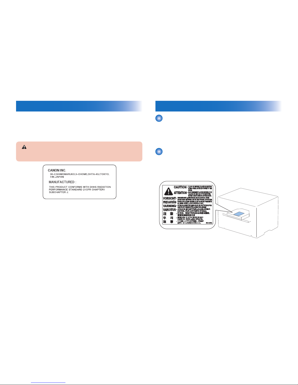
Laser Safety
About Laser Beams
Laser radiation may be hazardous to human. The laser scanner unit mounted in this device is
sealed in the protective housing and the external cover to prevent laser beams from leaking
to the environment. As long as the device is operated under normal conditions, users are
safely guarded from laser leaks.
Handling Laser Scanner Unit
Before providing service works for the laser scanner unit and its peripherals, ensure to turn
off the power of the device.
Any cover with potential dangers of laser beam reection has afxed the caution label at the
position shown in the gure below.
F-0-2

0-3
0-3
Toner Safety
About Toner
Toner is a non-toxic material composed of plastic, iron, small amount of pigment, etc.
Never throw toner in ames to avoid explosion.
Handling Adhered Toner
• Use dry tissue paper to wipe off toner adhered to skin or clothes and wash in water.
• Never use warm water for cleaning up toner to prevent toner particles from being able to
soak into bers permanently.
• Toner particles are reactive with vinyl polymers. Avoid contacting these materials.
Notes on Handling Lithium Battery
Replacing with wrong battery types may cause explosion.
Follow instructions to dispose used batteries properly.
Notes on Assembly/Disassembly
Follow the items below to assemble/disassemble the device.
1. Disconnect the power plug to avoid any potential dangers during assembling/disassembling
works.
2. If not specially instructed, reverse the order of disassembly to reinstall.
3. Ensure to use the right screw type (length, diameter, etc.) at the right position when
assembling.
4. To keep electric conduction, binding screws with washers are used to attach the grounding
wire and the varistor. Ensure to use the right screw type when assembling.
5. Unless it is specially needed, do not operate the device with some parts removed.
6. Never remove the paint-locked screws when disassembling.

1
1
Product Overview
Product Overview
■Product Lineup
■Product Features
■Specications
■Parts Name
1
1
1-2
1-2
Product Overview > Product Features > Product Features
Product Overview > Product Features > Product Features
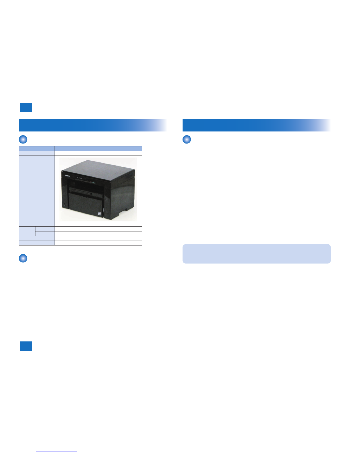
Product Lineup
Host Machine
Model name MF3010
Conguration
3in1 single-sided platen
Design
ADF
-
Engine
2-sided
-
1-sided
Yes
LAN Port
-
FAX
-
Options
None
T-1-1
Product Features
Product Features
1. Compact/high-speed printer
This machine is a high-speed B&W printer with a compact body design and the print speed
of 19 ppm (LTR).
2. Reduced standby time and low energy consumption
This machine uses the on-demand xing method in which power is supplied to the heater
only at printing.
This realized the reduction of standby time and low energy consumption during standby.
3. Reduced operation noise and stabilized image quality
This machine uses the belt drive method for the Main Motor's drive transmission.
The operation noise is reduced and image quality is stabilized compared to the
conventional gear drive method (see NOTE).
4. Improved user operability
User operability is improved by concentrating the maintenance processes (jam removal
and cartridge replacement) in a single location at the Upper Cover.
Note:
By changing the drive method from gear to belt, uneven cycle of the Photosensitive
Drum is reduced. This makes it possible to realize stabilized image quality.

1
1
1-3
1-3
Product Overview > Specications > Product Specications
Product Overview > Specications > Product Specications
Specications
Product Specications
Copyboard Fixed Copyboard
Machine installation method Desktop
Light source LED (RGB)
Image reading method CIS (color)
Photosensitive medium OPC Drum
Exposure method Laser beam (semiconductor laser)
Charging method Roller charging
Developing method Toner projection
Transfer method Roller transfer
Separation method Curvature separation
Pickup method Pickup Tray: Pad separation method
Multi-purpose Tray: None
Delivery method Face-down
Drum cleaning method Blade cleaning
Fixing method On-demand method
Toner supplying method Toner Cartridge replacement
Toner level detection None
Document type Sheet
Maximum document size 216 mm x 297 mm
Magnication ratio 100 % magnication
50 to 200 % (in increments of 10 %)
Resolution at reading 600 dpi × 400 dpi / 600 dpi × 600 dpi *
Print resolution 600 dpi × 400 dpi / 600 dpi × 600 dpi *
Warm-up time 10 sec. or less (when replacing the Toner Cartridge with a new
one: 42 sec. or less)
First print time Approx. 7.7 sec. or less (LTR, default setting)
First copy time Approx. 12 sec. or less (LTR, default setting)
Print speed 19 ppm (LTR, initial setting)
12 ppm (when output adjustment mode is used)
Copy speed 19 ppm (LTR)
Paper size Fixed size:
A4, B5, A5, LGL, LTR, Statement, Executive, Ofcio, B-ofcio,
M-ofcio, Government-Letter, Government-Legal, Foolscap,
A-foolscap, Envelope COM10, Envelope C5, Envelope B5,
Envelope DL
Custom size:
Width: 76.2 to 216 mm, Length: 127 to 356 mm
Paper types Plain paper (60 to 89 g/m
2
), Heavy paper (90 to 163 g/m2), Rough
paper (60 to 163 g/m2), Transparency, Label, Envelope
Pickup Tray capacity Approx. 150 sheets (plain paper: 60 to 80 g/m
2
)
Delivery Tray capacity Approx. 100 sheets (plain paper: 60 to 80 g/m
2
)
Environment temperature range 10 to 30 degrees Centigrade
Environment humidity range 20 to 80 %
Duplex method None
Host Interface Standard: USB/Hi-speed USB, Options: None
Hard disk capacity Standard: None, Options: None
Memory capacity Standard: 64 MB, Options: None
Power supply AC120 to 127V +/- 10 %, ( 50,60 Hz +/- 2 Hz)
AC220 to 240V +/- 10 %, ( 50,60 Hz +/- 2 Hz)
Maximum power consumption 900 W or less (120 V), 960 W or less (230 V)
Power consumption 460 W or less (120 V), 450 W or less (230 V)
External dimensions (W x D xH) 372 × 276 × 254 mm
Weight Approx. 8.2 kg (including Toner Cartridge)
*: Resolution switching
With this machine, 2 types of resolution can be switched by setting "Copy Type" on the
printer driver.
Speed priority (at the time of shipment): 600 dpi × 400 dpi
Resolution priority: 600 dpi × 600 dpi
T-1-2
1
1
1-4
1-4
Product Overview > Parts Name > External View > Rear side of the machine
Product Overview > Parts Name > External View > Rear side of the machine
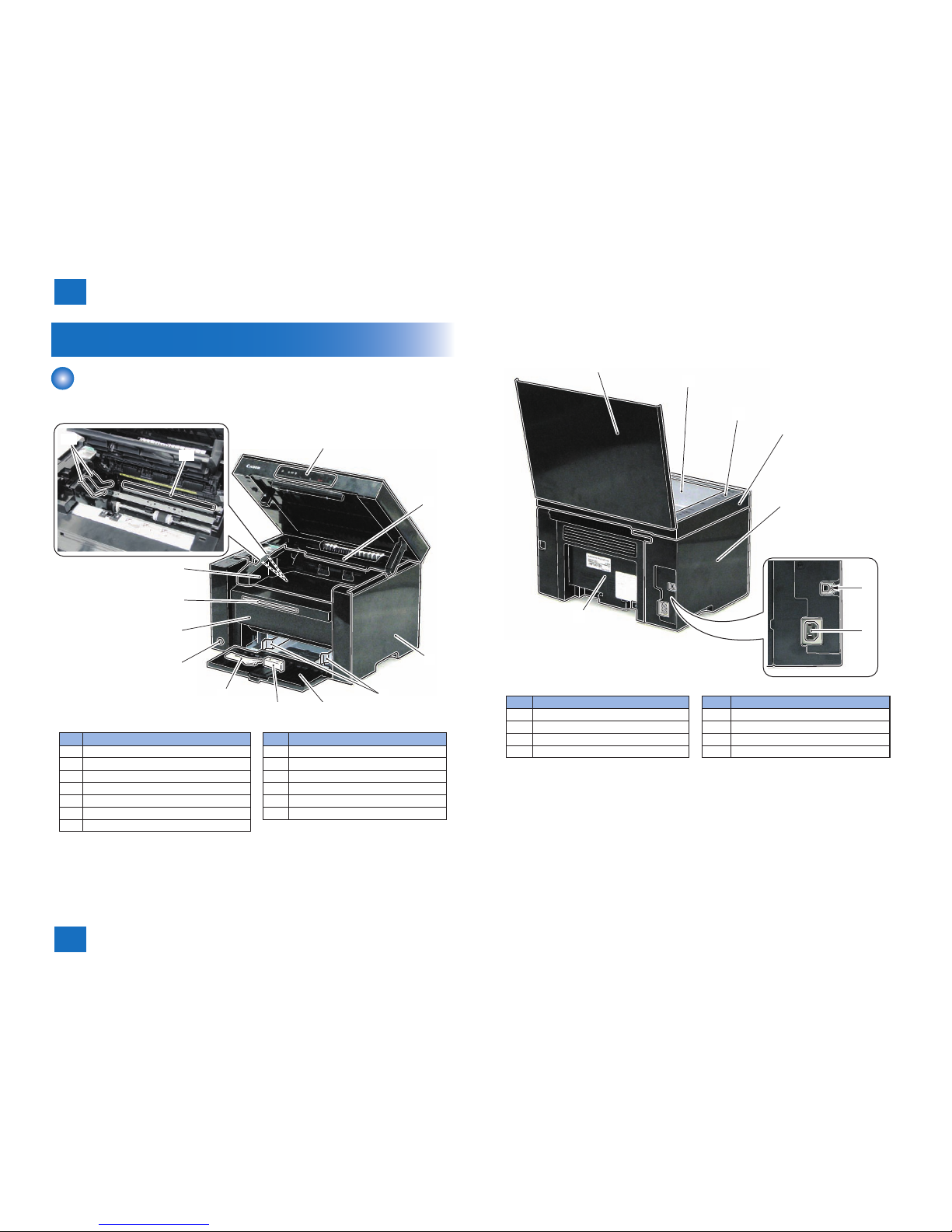
Parts Name
External View
■Front side of the machine
[3]
[11]
[10]
[6]
[7]
[5]
[9]
[8]
[1]
[2]
[4]
[13]
[12]
No. Name No. Name
[1] Control Panel Unit [8] Power Switch
[2] Upper Cover [9] Front Cover Unit
[3] Right Cover [10] Delivery Auxiliary Tray
[4] Pickup Tray Paper Guides [11] Delivery Tray
[5] Pickup Tray [12] Toner Cartridge Guide
[6] Pickup Tray Trailing Edge Paper Guides [13] Transfer Roller
[7] Small Size Paper Guides
F-1-1
■Rear side of the machine
[1]
[2]
[3]
[4]
[5]
[8]
[7]
[6]
No. Name No. Name
[1] Copyboard Cover [5] Left Cover
[2] Copyboard Glass [6] USB Device Port
[3] Copyboard Upper Cover [7] Power Supply Cord Slot
[4] Copyboard Lower Cover [8] Rear Cover
F-1-2
1
1
1-5
1-5
Product Overview > Parts Name > Control Panel
Product Overview > Parts Name > Control Panel
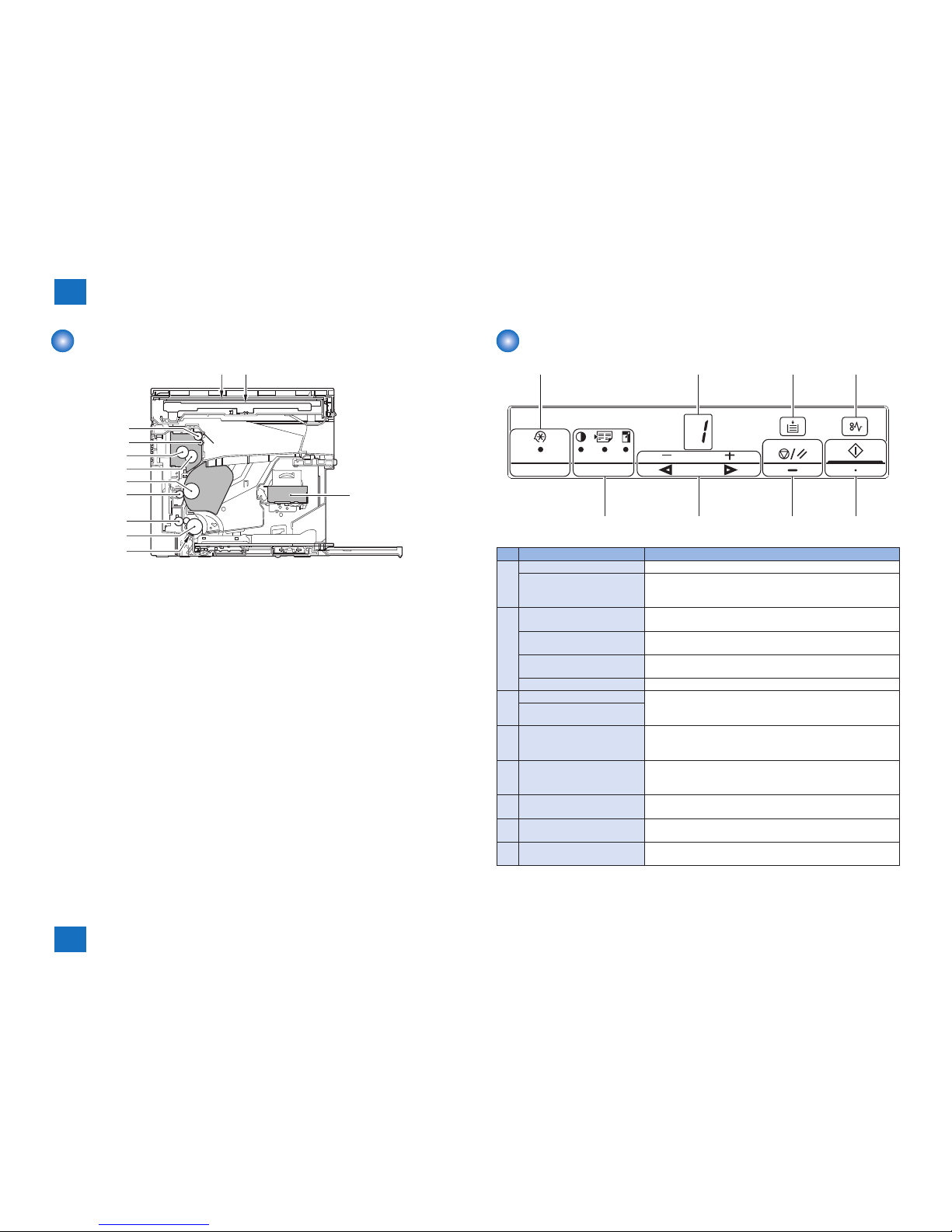
Cross Section View
[10]
[1]
[11]
[2]
[3]
[4]
[5]
[6]
[7]
[8]
[9]
[12]
No. Name No. Name
[1] Copyboard Glass [7] Photosensitive Drum
[2] CIS Unit [8] Fixing Film Unit
[3] Separation Pad [9] Fixing Pressure Roller
[4] Pickup Roller [10] Fixing Assembly
[5] Feed Roller [11] Delivery Roller
[6] Transfer Roller [12] Laser Scanner Unit
F-1-3
Control Panel
[1]
[2] [3]
[5]
[6][7][8]
[4]
No. Name Function
[1] Menu setting lamp (green) Blinking: Menu is being set.
Menu setting key Menu setting mode is entered.
Pressing this key while menu is being set returns to one layer
above.
[2] Density setting amp (green) Blinking: Density is being set.
Lit: When changing from the initial value
Page aggregation setting lamp
(green)
Blinking: Reduced layout/ID Card copy is being set.
Lit: When changing from the initial value
Enlargement/reduction setting
lamp (green)
Blinking: Enlargement/reduction is being set.
Lit: When changing from the initial value
Copy setting key Copy setting items are switched by each press of this key.
[3] - (◄) key The menu items are switched or the setting values are
increased/decreased in the menu setting mode. Also, the
setting values of copy setting items are increased/decreased.
+ (►) key
[4] Stop/reset key The job is stopped.
Pressing this key while menu is being set returns to one layer
above.
[5] Start/OK key Copy operation is started.
In the menu setting mode, the menu items are selected or the
setting values are determined.
[6] Jam occurrence lamp (orange) Blinking: At occurrence of a jam
Lit: At occurrence of a service error
[7] Out of paper lamp (orange) Blinking: When paper on the Pickup Tray runs out
Lit: At occurrence of a service error
[8] Indicator (green) The setting values of copy setting items or the status of this
product are displayed.
F-1-4
T-1-3

2
2
Technical Overview
Technical Overview
■Basic Conguration
■Controller System
■Original Exposure System
■Laser Exposure System
■Image Formation System
■Fixing System
■Pickup Feed System
■External And Controls System

2
2
2-2
2-2
Technical Overview > Basic Conguration > Basic Sequence > Basic Sequence of Operation
Technical Overview > Basic Conguration > Basic Sequence > Basic Sequence of Operation
Basic Conguration
Conguration function
The machine may be broadly divided into the following 7 functional blocks: engine control
system,original exposure system, laser exposure system, image formation system, pickup
feed system, xing system, and external and control system.
Original exposure system
External device
Engine control
system
Laser exposure system
Pickup feed system
Image formation system
Fixing system
External and controls system
F-2-1
Basic Sequence
■Basic Sequence of Operation
The engine controller controls the operation sequence. The following table provides an outline
of machine operation occurring from when the power switch is turned on to when printing
ends and Main Motor (M1) stop, indicating the purposes of intervals and engine operation.
Interval Purpose Remarks
WAIT
(Wait)
From power-ON until initial
drive for Main Motor (M1) is
completed.
To clear potential from the drum
surface and to clean the transfer
roller.
Also to bring the heater
temperature up to the targeted
temperature.
Detect whether the
Toner cartridge is
installed or not.
STBY
(Standby)
From the end of the WAIT
period or the LSTR period
until the print command is
sent from the main controller.
Or, from the end of the LSTR
period until power switch is
turned OFF.
To keep the printer ready to
print.
INTR
(initial
rotation)
From the input of the print
command from the main
controller until the Pickup
Solenoid (SL1) is turned ON.
To stabilize the photosensitive
drum sensitivity in preparation
for printing. Also to clean the
transfer roller.
PRINT
(print)
From the end of the INTR
period until the Paper
Leading Edge Sensor
(PS751) detects the trailing
edge of paper.
To form image on the
photosensitive drum based on
the VIDEO (/VDO, VDO) signals
input from the main controller,
and to transfer the toner image
onto paper.
LSTR
(last
rotation)
From the end of PRINT
period until the Main Motor
(M1) stops.
To deliver the last paper
completely out of the printer.
Return to the INTR
period as soon as
another print command
is sent from the main
controller.
T-2-1
2
2
2-3
2-3
Technical Overview > Basic Conguration > Basic Sequence > Print Sequence
Technical Overview > Basic Conguration > Basic Sequence > Print Sequence
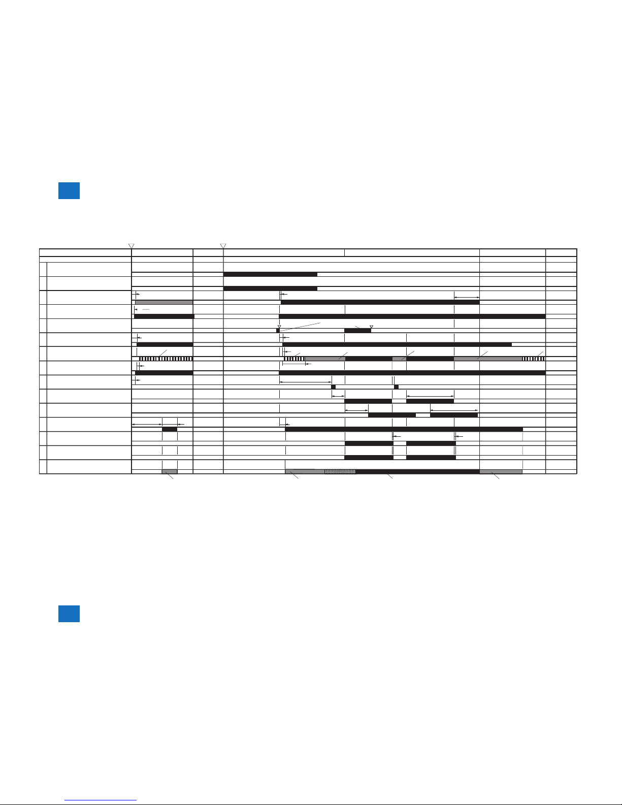
■Print Sequence
Fixing heater
CIS Unit
Reader Motor (M3)
Sequence
WAIT
Power-on
Start KEY
0.9
0.1
0.3
0.1
Max.1.5
2.4
0.5
0.5
0.06
0.06
0.9
2.0
2.0
Forcible emission
Forcible emission
Masking emission Masking emission Masking emission
1.3Print temperature control
Print command
Print command
Waiting for
a print command
0.5
1.1
0.1
0.8
Max.4.1
1.1
Cleaning bias Cleaning bias Print bias Cleaning bias
BD emission/
Forcible emission
Controls at 80 C
Relay
1
Print command
Scanner motor (M2)
Laser diode
Main motor (M1)
Pickup solenoid (SL1)
Leading edge sensor (PS751)
Fixing delivery sensor (PS701)
Primary charging bias (DC)
Developing bias (AC)
Developing bias (DC)
Transfer bias
STBY INTR PRINT LSTR STBY
(Unit:Seconds)
2
3
4
5
6
7
8
9
10
11
12
13
14
15
F-2-2

2
2
2-4
2-4
Technical Overview > Basic Conguration > Basic Sequence > Power-On Sequence
Technical Overview > Basic Conguration > Basic Sequence > Power-On Sequence
■Power-On Sequence
The sequences from the power-ON to the STBY period are described below.
1) Power-ON.
2) CPU initialization.
3) Video interface communication start.
4) Residual paper check.
Detecting paper presence by each sensor signaling.
5) Initial drive for Main Motor (M1).
6) Initial drive for Fixing Heater (H1).
Controlling xing temperature targeting for 120 deg C.
7) Initial drive of the Scanner Motor (M2).
8) High-voltage control.
Detect cartridge presence after primary charging AC bias is applied.
Cleaning transfer roller.
9) Failure/Abnormality check.
Detecting xing unit failure and door open during above periods.
2
2
2-5
2-5
Technical Overview > Controller System > Engine Controller > General description
Technical Overview > Controller System > Engine Controller > General description
Controller System
Main Controller
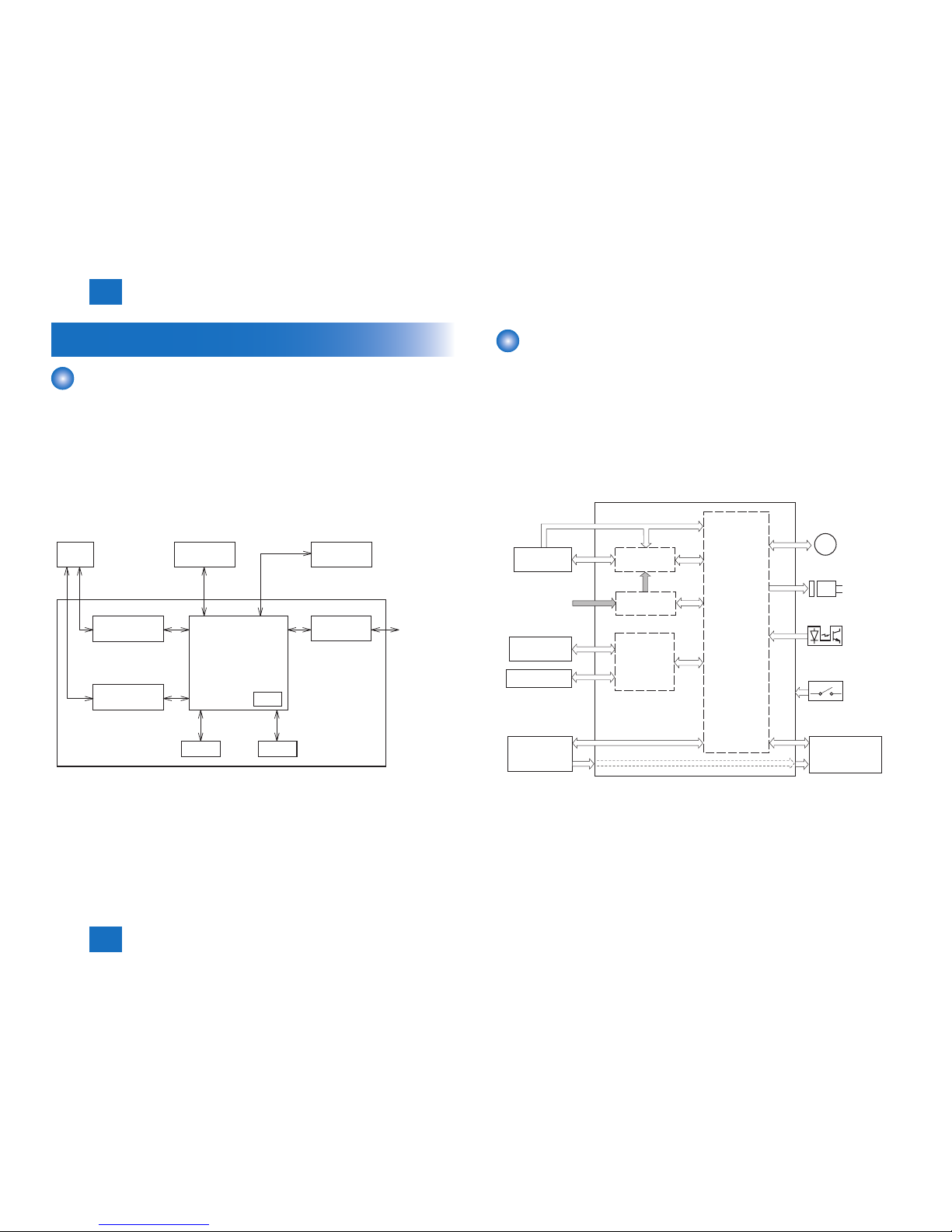
■Overview
The Main Controller receives print information from the Reader and external equipment
(computer, etc.). Video data is created from the received print information, and is sent to the
Engine Controller.
There are 2 types of print information from the external equipment: engine command data to
exchange the status or unique information of a printer and dot data for printing.
In the case of receiving dot data, video data is created and is sent to the Engine Controller.
In the case of receiving engine command data, printer status is returned to the external
equipment after communicating with the Engine Controller.
EXTERNAL
DEVICE
USB
INTERFACE
CONTROL PANEL
ENGINE
CONTROLLER
DRAM
MAIN CONTROLLER
EEPROM
READER
CONVERTER
ANALOG TO DIGITAL
MOTOR DRIVER
DC/DC CONVERTER
CPU
ASIC
F-2-3
Engine Controller
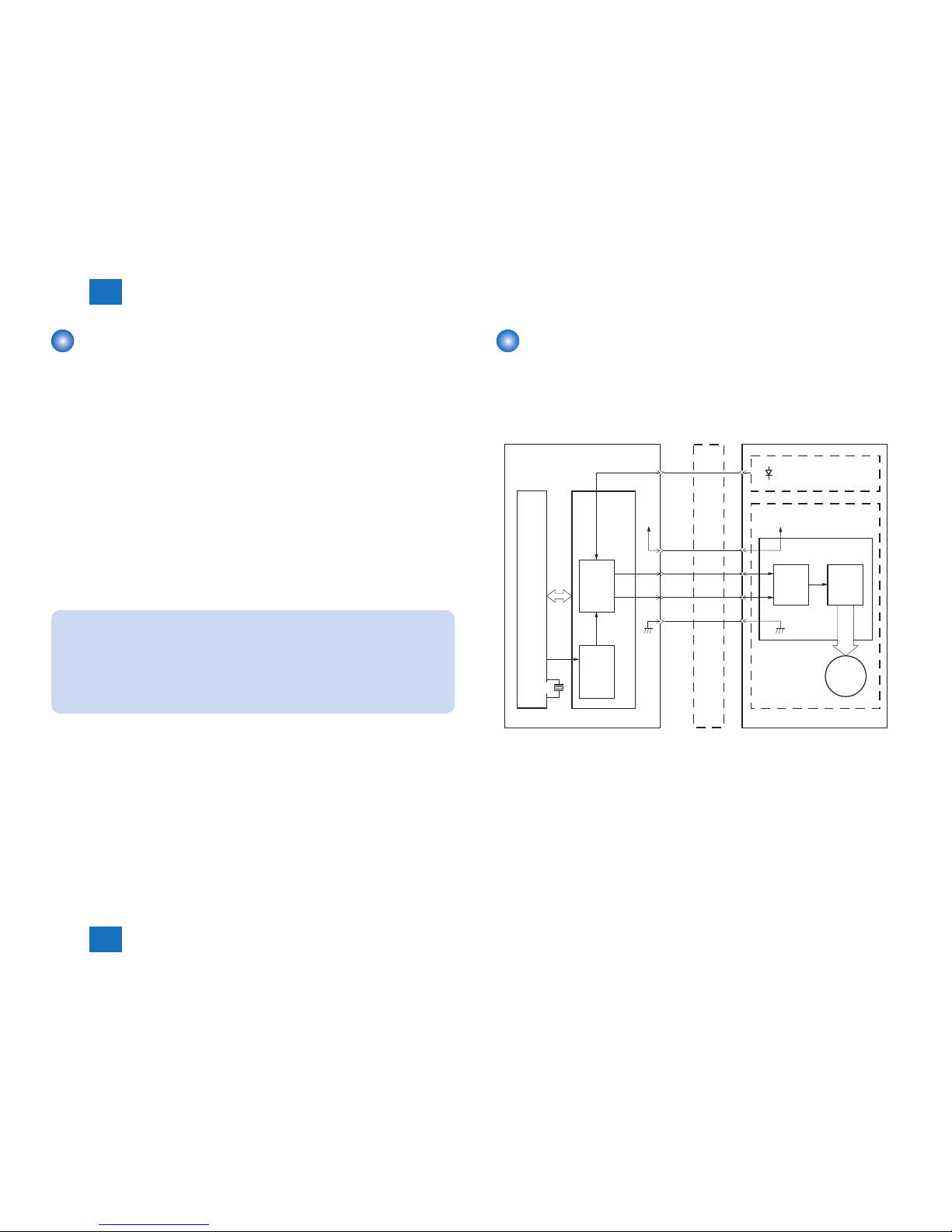
■General description
Engine controller is the circuit to control the operation sequence of the host machine and it is
controlled by the CPU inside the engine controller.
When the Power Switch (SW1100) is turned ON and DC power is supplied through the low
voltage power inside engine controller, CPU starts the printer operation control.
Then, CPU drives the loads such as laser diode, motors and solenoids etc. according to the
image data that is input by the main controller when status becomes stand-by mode.
The following is the block diagram of this circuit.
AC input
Fixing
assembly
Motor
M
Transfer roller
High-voltage
power supply
Low-voltage
power supply
Laser scanner
unit
Solenoid
Main controller
Toner Cartridge
Sensor
CPU
Switch
Engine controller
Fixing control
F-2-4

2
2
2-6
2-6
Technical Overview > Controller System > Service Works > Notes on service works
Technical Overview > Controller System > Service Works > Notes on service works
Service Works
■At parts replacement
No work is required for this product at parts replacement.
■Maintenance
No periodically replaced parts, durable parts or periodical service is set for this product.
■Notes on service works
None.
2
2
2-7
2-7
Technical Overview > Original Exposure System > Major Components
Technical Overview > Original Exposure System > Major Components
Original Exposure System
Overview
item function / method
document exposure
LED
document scan
Scan by the shift of the CIS Unit
scanning resolution
600 dpi x 400 dpi, 600 dpi x 600 dpi (Horizontal x Vertical)
number of gradations
256 gradations
magnication
50 % to 200 % (10 % increment)
Horizontal: image processing by Main Controller PCB
Vertical: change of carriage shift speed, image processing by Main
Controller PCB
lens
CIS / Color
CIS Unit
number of lines: 1 line
number of pixels: 5148 pixels as total pixels (5104 pixels as effective
pixels)
maximum document scanning width: 216 mm
CIS Unit drive control
drive control by Reader motor (M3)
document size detection
none
T-2-2
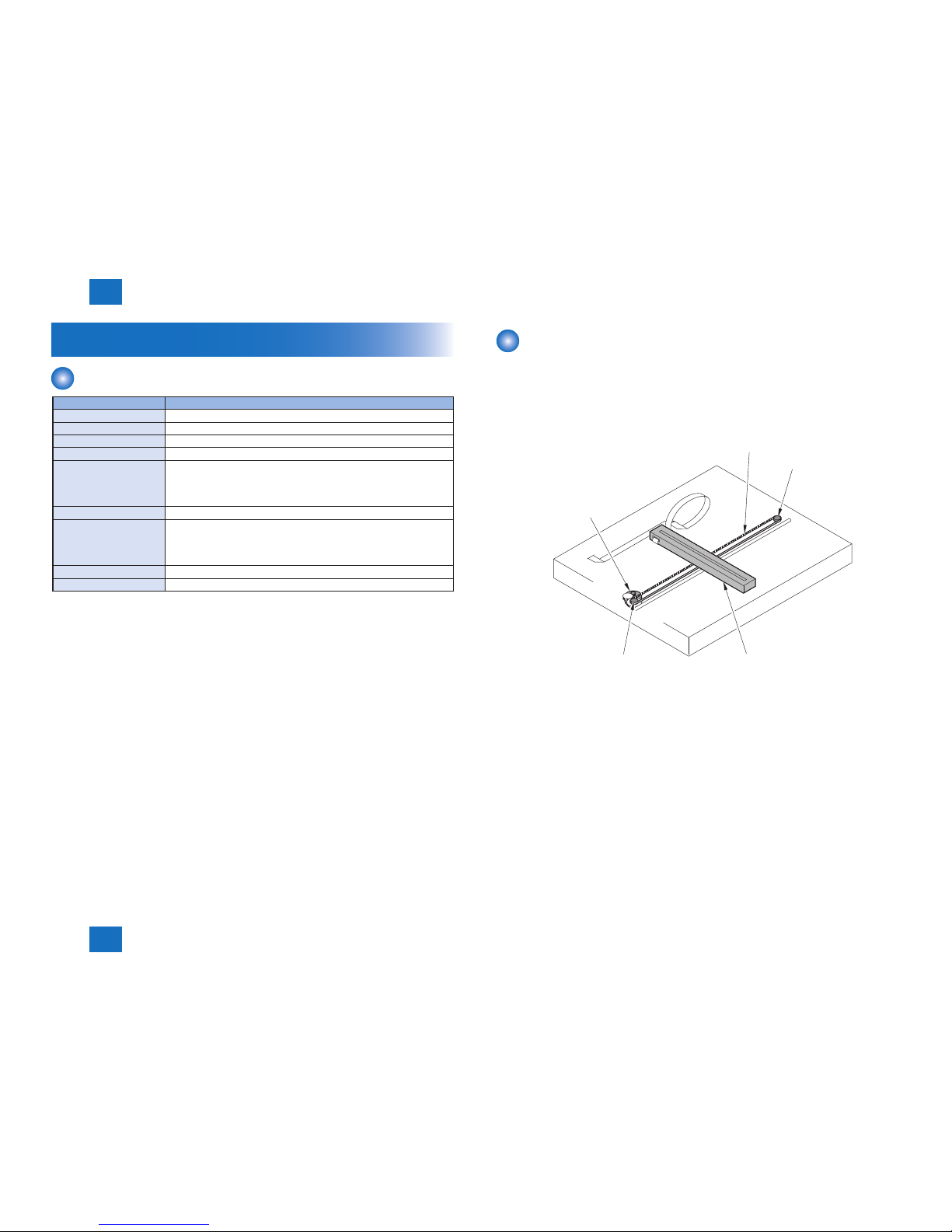
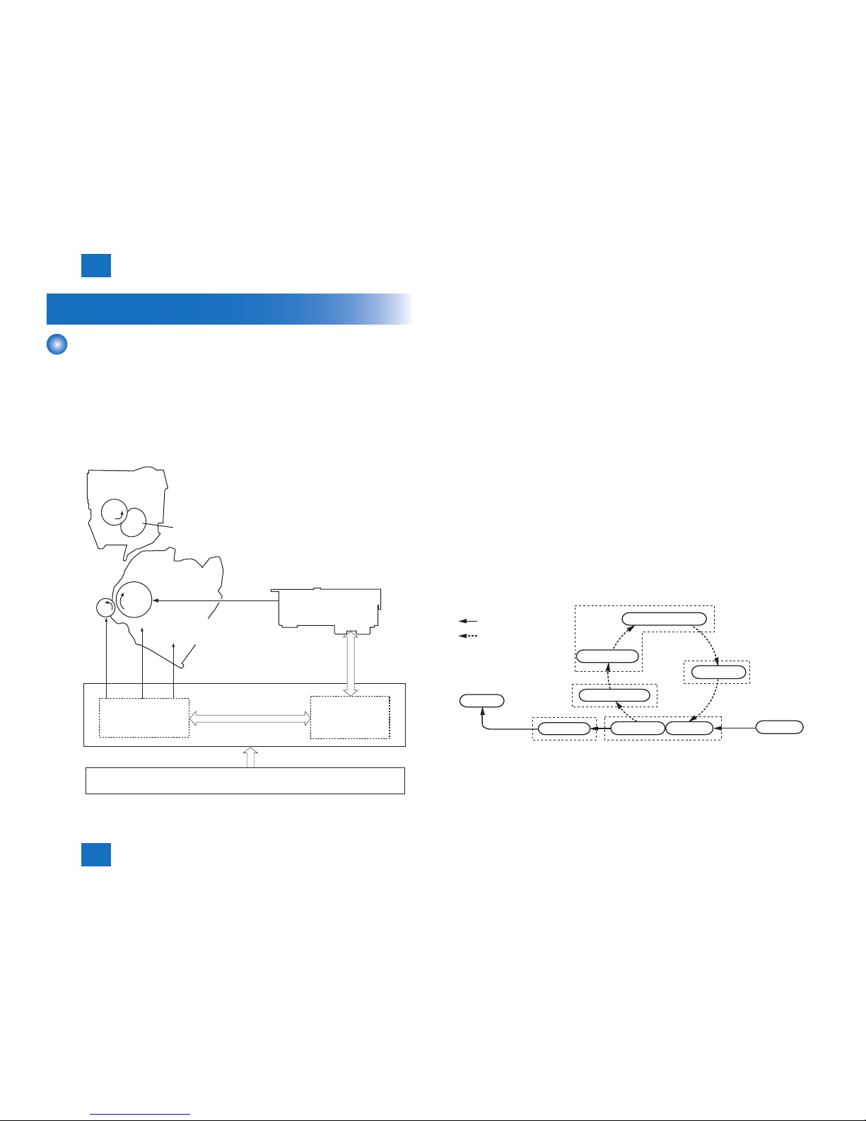
Major Components
Followings are the major components for Document Exposure System.
• The CIS Unit to scan document
• The Reader motor, the drive pulley, the drive belt, to shift the CIS Unit
In image scanning control, the CIS Unit is shifted by rotating the Reader motor based on the
drive signal from the Engine Controller PCB and scan the original on the copyboard glass.
Drive Belt
Drive Pulley
Drive Pulley
CIS Unit
Reader Motor(M3)
F-2-5

2
2
2-8
2-8
Technical Overview > Original Exposure System > Service Works > Notes on service works
Technical Overview > Original Exposure System > Service Works > Notes on service works
Service Works
■At parts replacement
No work is required for this product at parts replacement.
■Maintenance
No periodically replaced parts, durable parts or periodical service is set for this product.
■Notes on service works
None.
2
2
2-9
2-9
Technical Overview > Laser Exposure System > Overview > Overview
Technical Overview > Laser Exposure System > Overview > Overview
Laser Exposure System
Overview
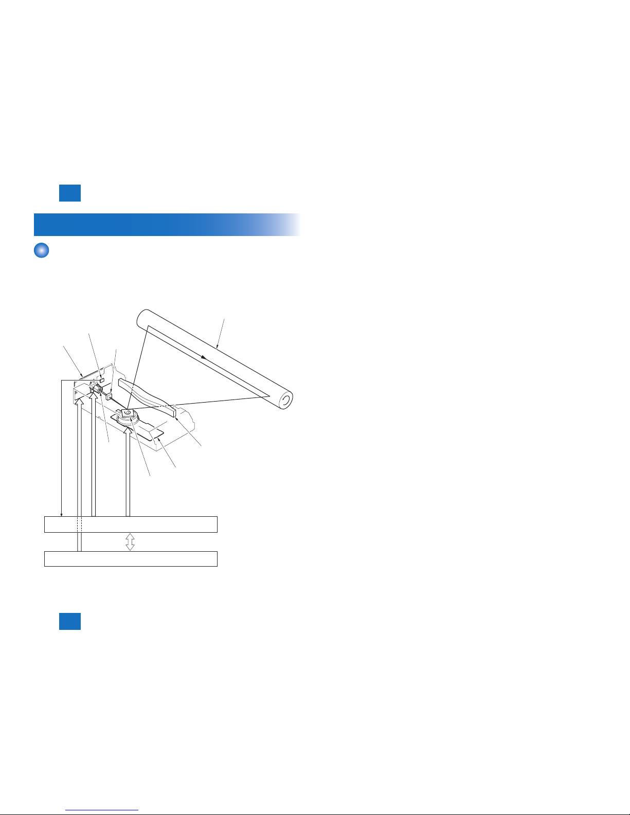
■Overview
The laser exposure system forms static latent images on the photosensitive drum according
to the VIDEO signals sent from the main controller, and is comprised of the laser driver and
scanner motor, etc. These are controlled by the engine controller. The following is the outline.
Laser unit
Scanner Motor (M2)
Four-faced mirror
Cylindrical lens
Photosensitive drum
Engine Controller
BD INPUT signal
VIDEO signal
LASER CONTROL signal
SCANNER MOTOR
SPEED CONTROL signal
Main controller
Focus lens
BD sensor
Collimator
lens
F-2-6
The operational sequence of the laser scanner unit is described below.
1) When the Main controller sends print instruction command, the Engine controller rotates
the Four-faced mirror, causing the Scanner Motor (M2) to rotate.
2) When the Scanner Motor (M2) starts to rotate, the Engine controller emits the laser forcibly
using the Laser control signal, causing the Engine controller to start rotation control for the
Scanner Motor (M2).
3) The Engine controller controls to keep a constant speed of rotation of the Scanner Motor
(M2) using the Scanner motor speed control signal.
4) After the rotation speed of the Scanner motor reaches its target, the Main controller sends
VIDEO signals to the Laser driver PCB.
5) The Laser driver emits laser diode according to these signals.
6) The laser beam passes through the collimator lens and the cylindrical lens and enters the
Four-faced mirror rotating at a constant speed.
7) The laser beam reected by the Four-faced mirror is focused on the Photosensitive drum
via the image-forming lens at the front of the Four-faced mirror.
8) When the Four-faced mirror rotates at a constant speed, the laser beam on the
Photosensitive drum is scanned on the Photosensitive drum at a constant speed.
9) When the Photosensitive drum rotates at a constant speed and the laser beam is scanned
on the Photosensitive drum at a constant speed, latent images are formed on the
Photosensitive drum.
2
2
2-10
2-10
Technical Overview > Laser Exposure System > Controlling the Laser Activation Timing > Horizontal Sync Control
Technical Overview > Laser Exposure System > Controlling the Laser Activation Timing > Horizontal Sync Control
Controlling the Laser Activation Timing
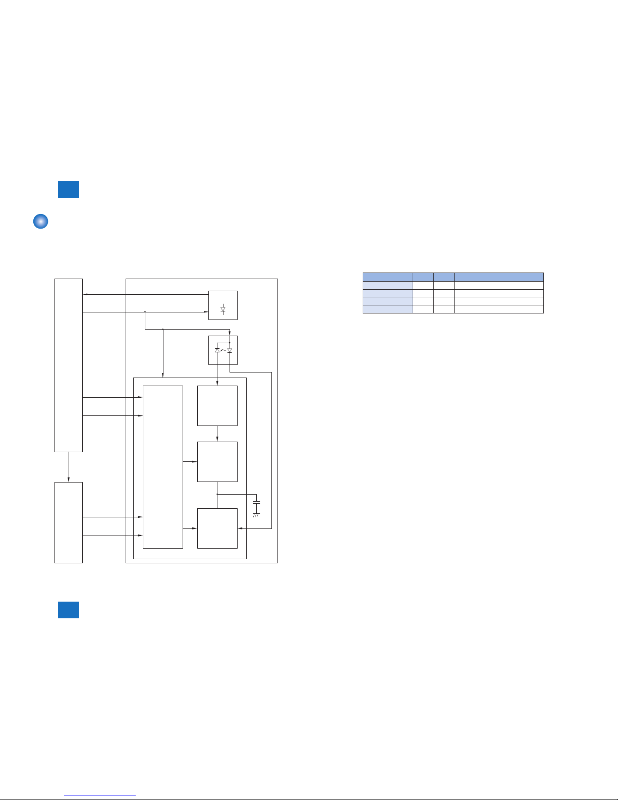
■Laser ON/OFF Control
In this control, the laser driver turns on/off the laser diode (LD) according to the laser control
signal sent from the engine controller.
The following is the circuit diagram of the laser control.
Engine
Controller
Main
Controller
Laser driver PCB
Laser driver IC
BD Sensor
LDPD
C1
CNT1
CNT0
VOD
/VOD
Sample hold
circuit
Drive
circuit
Comparator
Logic PCB
/BD
+3.3V
/BDI
F-2-7
The engine controller sends the laser control signals (CNT0, CNT1) for changing the
operation mode of the laser to the logic circuit in the laser driver IC, as well as the video
signals (VDO, /VDO) for image formation.
The laser driver IC executes laser control according to the combination of the CNT0, CNT1
signals.
The following is the combination of the laser control signal (CNT0, CNT1).
Operation mode CNT0 CNT1 Remarks
Discharge L L The capacitor (C1) is discharged.
Data output H H At normal print
APC H L At using APC
Forced OFF L H At using image mask
■Horizontal Sync Control
This is the control to adjust the writing position in the image horizontal direction.
The following is the details of control procedure.
1) The engine controller controls the laser control signal during unblanking (*) to emit the laser
diode (LD) forcibly.
2) The BD PCB exists on the scanning route of the laser beam, which is sent to the BD PCB.
3) The BD PCB detects this laser beam, creates BD input signal (/BDI) and sends it to the
engine controller.
4) The engine controller creates horizontal sync signals (/BD) based on /BDI signal and sends
the /BD signal to the main controller.
5) When /BD signal is input, the main controller outputs the video signal (VDO, /VDO) to the
engine controller to adjust the writing position in image horizontal direction.
*: Unblanking period
The period during which the laser diode is emitted in non-image area.
T-2-3
2
2
2-11
2-11
Technical Overview > Laser Exposure System > Laser Scanner Motor Control > Overview
Technical Overview > Laser Exposure System > Laser Scanner Motor Control > Overview
Laser Control
■Auto Power Control (APC)
This is the control to emit a constant level of laser diode.
There are two types of APC; initial APC (note 1), and line space APC (note 2). The laser
driver executes the same procedure for both controls. The following is the details of the
control procedure.
1) When the laser control signal enters APC mode (CNT0=H, CNT1=L), the laser driver emits
LD in APC mode.
2) The emission level of LD is detected with photo diode (PD), converted from current output
to voltage, and compared with the standard voltage (voltage equivalent to the target laser
level).
3) The laser driver controls the laser current to achieve the voltage of LD target level.
4) When the laser control signal enters LD forced OFF mode, the LD is forcibly turned off. The
laser driver saves the adjusted laser intensity to the capacitor (C1).
NOTE:
1. Initial APC
APC that is executed during initial rotation. APC adjusts laser intensity and detects
faults in the laser.
2. Line space APC
APC that is executed during printing. Laser intensity for one line is adjusted before
writing one line.
Laser Scanner Motor Control
■Overview
This is the control to rotate the Scanner Motor (M2) at a constant speed to emit the laser
beam on the correct position on the photosensitive drum.
The following is the control circuit of the Scanner Motor (M2).
Engine controller
Motor driver PCB
BD PCB
Oscillator
Reference
clock
Frequency
comparator
Laser scanner unit
Integration
circuit
M
Scanner motor
driver IC
Scanner motor
ACC
DEC
/BDI
Drive
circuit
CPU ASIC
X501
+24VA
+24VA
The engine controller creates standard clock based on oscillation frequency of the oscillator
(X501); the cycles of the standard clock is compared with that of BD input signal (/BDI) with a
frequency comparator and the rotations of the Scanner Motor (M2) is monitored.
The engine controller sends the scanner motor acceleration signal (ACC) and scanner motor
deceleration signal (DEC) to the scanner motor driver according to the detected rotation
speed to control the rotation speed.
F-2-8

2
2
2-12
2-12
Technical Overview > Laser Exposure System > Service Works > Notes on service works
Technical Overview > Laser Exposure System > Service Works > Notes on service works
■Scanner Motor Fault Detection
This is the detection of faults in the laser scanner unit.
When the laser scanner unit falls into either of the following status, the engine controller
judges it as a fault in the laser scanner unit system and notices the status of fault to the main
controller.
The operations of the host machine are stopped.
1. Fault in BD input
At startup of the scanner, /BDI signal cannot be detected within 0.1 sec from the completion
of forced acceleration of the Scanner Motor (M2).
2. Fault in startup
During activating the Scanner Motor (M2) at startup of the scanner, the motor rotation
exceeds the specied range (98.3 to 102.1%).
3. Fault in control
After startup of the scanner completes correctly, /BDI signal exceeds the specied value of
cycle 10 consecutive times.
Service Works
■At parts replacement
No work is required for this product at parts replacement.
■Maintenance
No periodically replaced parts, durable parts or periodical service is set for this product.
■Notes on service works
None.
2
2
2-13
2-13
Technical Overview > Image Formation System > Overview/Conguration > Print Process
Technical Overview > Image Formation System > Overview/Conguration > Print Process
Image Formation System
Overview/Conguration
■Overview
The image formation system is the core of this equipment; it forms toner images on papers.
The image formation system is comprised of the following components.
The engine controller controls the laser scanner unit and high-voltage power supply circuit
and forms images based on the video signals on papers.
The following are the details of print process for this equipment and the functions of image
formation.
Fixing assembly
Cartridge
Photosensitive drum
To primary charging roller
To developing cylinder
Engine controller
TR
PRI
DEV
High-voltage
power supply
VIDEO signal
Main controller
CPU
Laser/scanner unit
Laser beam
Fixing Film
Pressure roller
Transfer roller
F-2-9
■Print Process
This explains the basic process of the operations that a printer executes for image formation.
The print process of this equipment is divided largely into 5 blocks, 7 steps.
Toner images are formed on papers by executing the steps of each block in order.
The following are the blocks of print process and the steps.
1. Static latent image formation block
Step 1: Primary charging
Step 2: Laser beam exposure
2. Development block
Step 3: Development
3. Transfer block
Step 4: Transfer
Step 5: Separation
4. Fixing block
Step 6: Fixing
5. Drum cleaning block
Step 7: Drum cleaning
Paper path
Rotational direction of
the drum
Electrostatic latent image formation block
Transfer block
Fixing block
Development
block
Drum cleaning
block
Delivery
Pick-up
4. Transfer5. Separation
6. Fixing
2. Laser beam exposure
3. Development
7. Drum cleaning
1. Primary charging
F-2-10
2
2
2-14
2-14
Technical Overview > Image Formation System > Overview/Conguration > Development Block
Technical Overview > Image Formation System > Overview/Conguration > Development Block
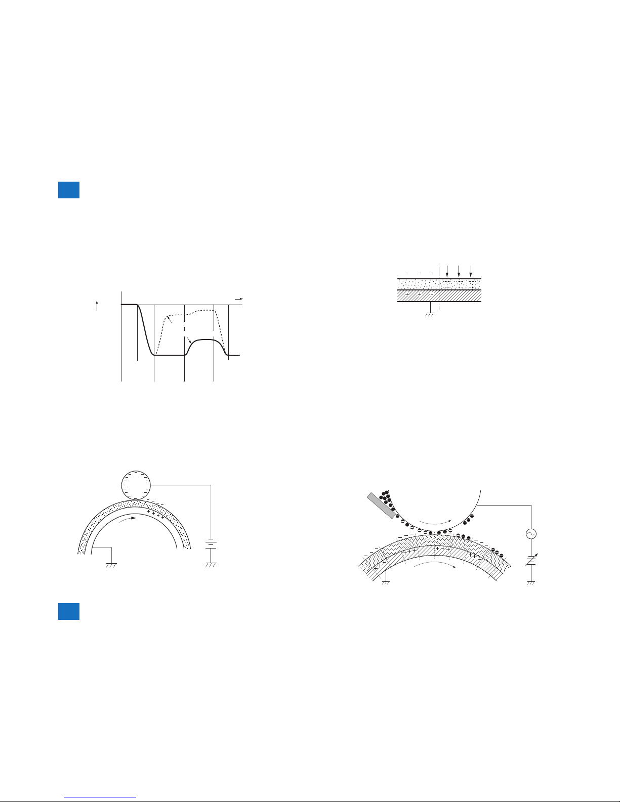
■Static Latent Image Formation Block
This block is comprised of two steps and forms static latent images on the photosensitive
drum.
When the nal step of this block completes, negative charge remains at dark areas on the
drum surface where laser beam has not been exposed, and negative charge is eliminated
from bright areas on the drum surface with laser beam exposed. The images on the drum
with negative charge are called static latent images because human eyes cannot detect them.
0
Time (t)
Surface
potential
(V)
Laser
beam
exposure
(step 2)
Transfer
(step 4)
Primary
charging
(step 1)
Primary
charging
(step 1)
Exposed area
Unexposed area
Step 1: Primary charging
For preparation of latent image formation, the surface of photosensitive drum is charged
with even negative potential. In this primary charging, the charge is applied from the primary
charging roller directly to the photosensitive drum.
DC bias is applied to the primary charging roller to maintain an even potential on the surface
of the photosensitive drum.
Primary charging roller
Photosensitive drum
DC bias
F-2-11
F-2-12
Step 2: Laser beam exposure
In this step, static latent images are formed on the photosensitive drum with laser beam.
When laser beams are scanned on the photosensitive drum negatively charged, bright areas
lose their charges, eliminating negative potential on the surface of the photosensitive drum;
on those portions, static latent images are formed.
Laser beam
Exposed
area
Unexposed
area
■Development Block
This block is comprised of one step; it puts toners to the static latent images on the surface of
the photosensitive drum and visualizes the images using toner projection development. The
toner projection development makes the toner jump on the surface of the photosensitive drum
and develops the images.
The toner (developer) used for this equipment is a one-component toner that comprises
magnetic body and resin, etc.
Step 3: Development
Toner is afxed to static latent images on the surface of the photosensitive drum.
The toner is charged negatively by friction between the developing cylinder and the surface of
the developing blade.
An area on the photosensitive drum exposed with laser beam has higher potential than the
developing cylinder; the potential difference between the drum surface and the cylinder
enables the toner to jump on the drum surface and makes them visible images.
AC bias superimposed with the development DC negative bias is applied to the developing
cylinder.
Blade
Developing cylinder
AC bias
DC bias
Photosensitive drum
Unexposed
area
Exposed area
Exposed area
Unexposed area
F-2-13
F-2-14
2
2
2-15
2-15
Technical Overview > Image Formation System > Overview/Conguration > Drum Cleaning Block
Technical Overview > Image Formation System > Overview/Conguration > Drum Cleaning Block
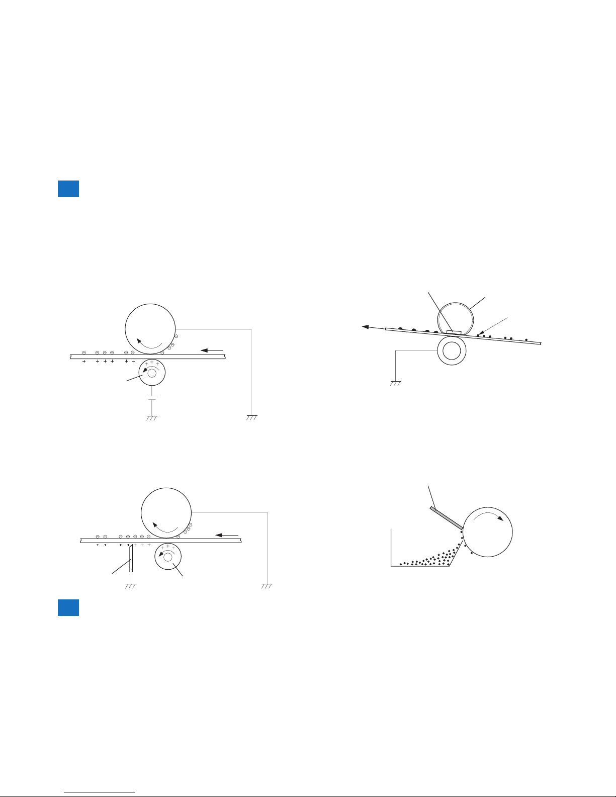
■Transfer Block
This block is comprised of two steps; it transfers toner images on the surface of the
photosensitive drum to papers.
Step 4: Transfer
In this step, toner images on the photosensitive drum are transferred to papers.
This equipment applies DC positive bias to the transfer roller facing the photosensitive drum
and charges papers positively. This enables toner negatively charged on the surface of the
photosensitive drum to be transferred to papers.
DC bias
Transfer roller
Photosensitive
drum
Media
Step 5: Separation
In this step, DC negative bias is applied to the static eliminator according to the elasticity of
papers to separate the papers from the photosensitive drum. The static eliminator is used to
stabilize the paper feed system (prevention of toner stray that appears as polka-dots on print
images in a low-temperature, low-humidity environment), and neutralizes the electric charge
at the back of papers.
Media
Transfer roller
Static charge eliminator
Photosensitive
drum
F-2-15
F-2-16
■Fixing Block
This block applies pressure and heat to papers and the toner on them to x toner images to
the papers.
Step 6: Fixing
This step employs on-demand xing that xes toner images transferred to papers on the
papers.
Fixing heater
Fixing film
Toner
Media
Pressure roller
■Drum Cleaning Block
The drum cleaning block removes the toner remained on the photosensitive drum.
Step 7: Drum cleaning
In this step, toner remained on the photosensitive drum is removed.
The cleaning blade scrapes the leftover toner on the surface of the photosensitive drum; the
toner is collected into the cleaner container.
By implementing the above step, the surface of the photosensitive drum is cleaned.
Cleaning blade
Cleaner container
Photosensitive
drum
F-2-17
F-2-18
 Loading...