

Canon ae1, ae2, m2, n1, p1 Installation Procedures Manual
...
FINISHER-AE1
SADDLE FINISHER-AE2
PUNCHER
UNIT-LIIMIINIIPI
INSTALLATION PROCEDURE
Follow the instructions herein when installing the Product to its host machine.
~%&~~4$~Z#3?~~5~13,
UTD?FJIR~Z@T
T
<
E$
b\o
PUB. F-IM-6673-000
PRINTED
IN
JAPAN
or
CHINA
1
.I
Page References for Installation
When installing the finisher and the puncher unit, first install the buffer path and unpack the finisher
then install them according to the following installation instructions.
When installing only the finisher: see
When installing the finisher and puncher unit at the same time: see
When installing the puncher unit after having installed the finisher: After following the procedure for installing only
the finisher
(P.12 - P.22),
see page
P.12.
P.23.
P.36.
(P.3 - P. 12),
and
1.2
Making
Pre-Checks
1.2.1
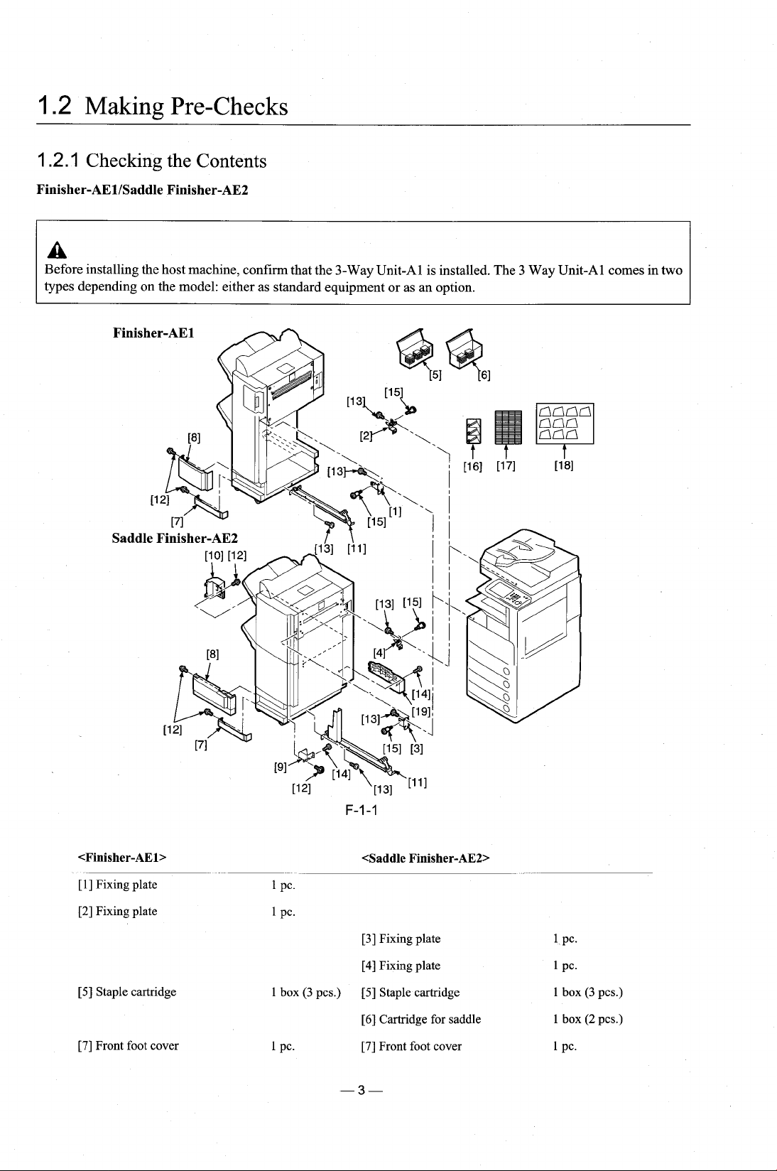
Finisher-AElISaddle Finisher-AE2
Checking the Contents
A
Before installing the host machine, confirm that the 3-Way Unit-A1 is installed. The 3 Way Unit-A1 comes in two
types depending on the model: either as standard equipment or as an option.
[I]
Fixing plate
[2]
Fixing plate
[5]
Staple cartridge
[7]
Front foot cover
1
1
box
PC.
(3
pcs.)
[3]
Fixing plate
[4]
Fixing plate
[5]
Staple cartridge
[6]
Cartridge for saddle
[7]
Front foot cover
1
1
1
1
1
PC.
PC.
box
box
PC.
(3
(2
pcs.)
pcs.)
[8]
Front lower extension cover
1
pc.
[8]
Front lower extension cover
1
PC.
Buffer
[l
11
Ground rail
[12]
Screw (RS tightening;
[13]
Screw (binding;
[15]
Stepped screw
[16]
Tray label
[17]
Settings label
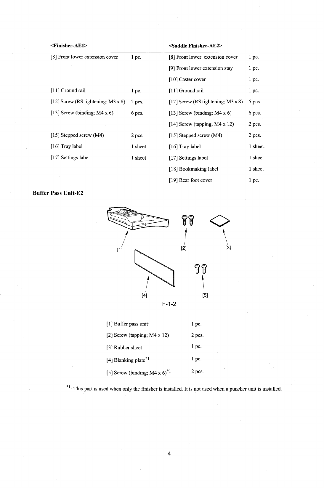
Pass Unit-E2
M3 x 8)
M4 x 6)
(M4) 2
1
PC.
2
pcs.
6
pcs.
pcs.
1
sheet
1
sheet
[9]
Front lower extension stay
[lo]
Caster cover
[l
11
Ground rail
[12]
Screw (RS tightening;
[13]
Screw (binding;
[14]
Screw (tapping;
[15]
Stepped screw
[16]
Tray label
[17]
Settings label
[18]
Bookmaking label
[19]
Rear foot cover
M4 x 6)
M4 x 12)
(M4)
M3 x 8)
1 PC.
1
PC.
1
PC.
5
pcs.
6
pcs.
2
pcs.
2
pcs.
1 sheet
1
sheet
1 sheet
1
PC.
[I]
Buffer pass unit
[2]
Screw (tapping;
[3]
Rubber sheet
[4]
Blanking plate*1
[5]
Screw (binding;
*':
This part is used when only the finisher is installed. It is not used when a puncher unit is installed.
M4 x 12)
M4 x 6)*l
1
2
1
1
2
PC.
pcs.
PC.
PC.
pcs.
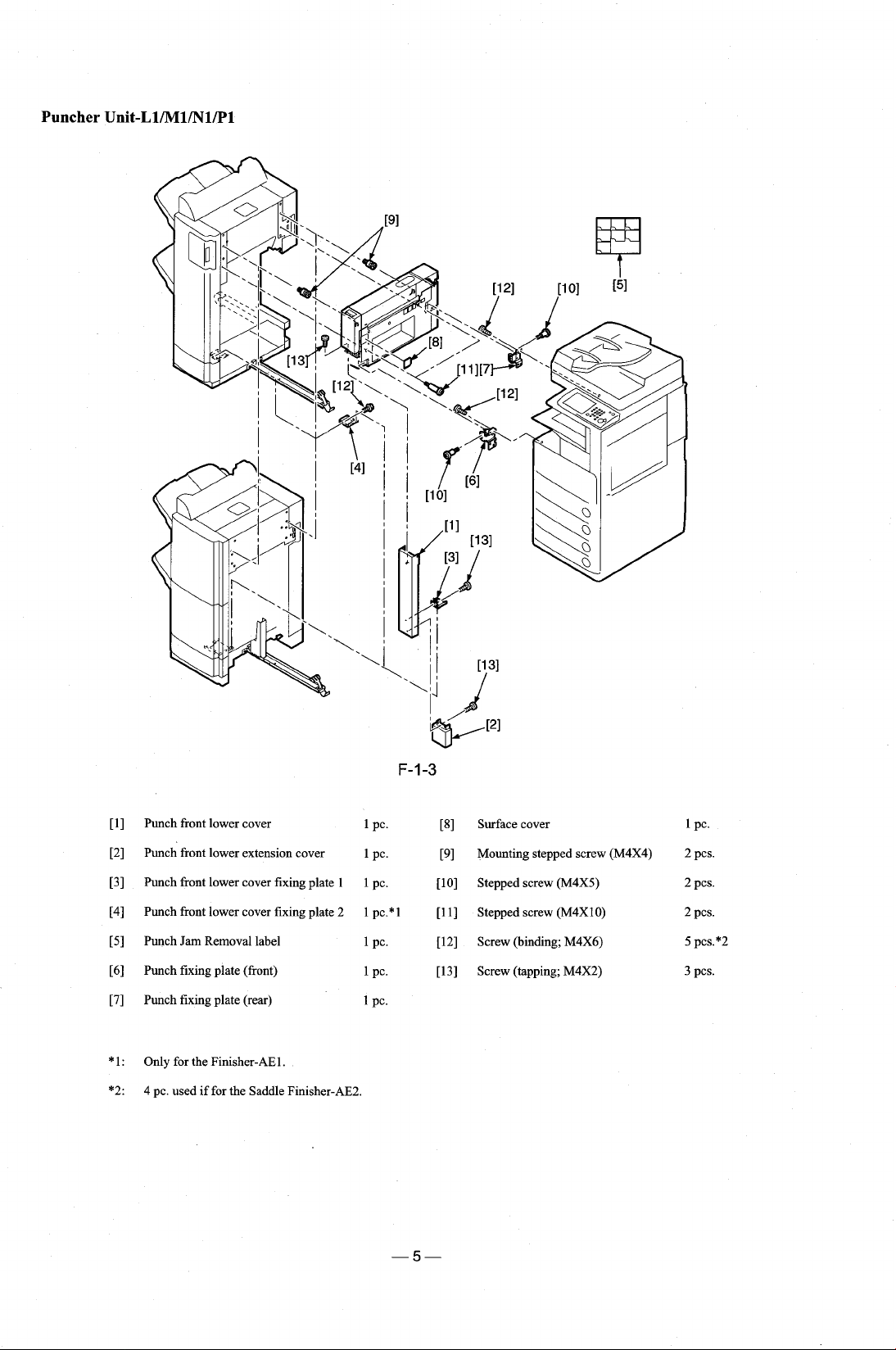
Puncher
Unit-Ll/Ml/Nl/Pl
[I] Punch front lower cover 1 PC. [8] Surface cover 1 PC.
[2] Punch front lower extension cover 1 pc. [9] Mounting stepped screw (M4X4) 2 pcs.
[3] Punch front lower cover fixing plate 1
[4] Punch front lower cover fixing plate 2
[5] Punch Jam Removal label
[6]
Punch fixing plate (front)
[7] Punch fixing plate (rear)
*
1 : Only for the Finisher-AEl
*2:
4 pc. used if for the Saddle Finisher-AE2.
.
1 pc. [lo] Stepped screw (M4X5) 2 pcs.
1 pc.*l [l 11 Stepped screw (M4X10)
1
PC. [12] Screw (binding; M4X6) 5 pcs.*2
1
PC. [13] Screw (tapping; M4X2) 3 pcs.
1 PC.
2
pcs.
I
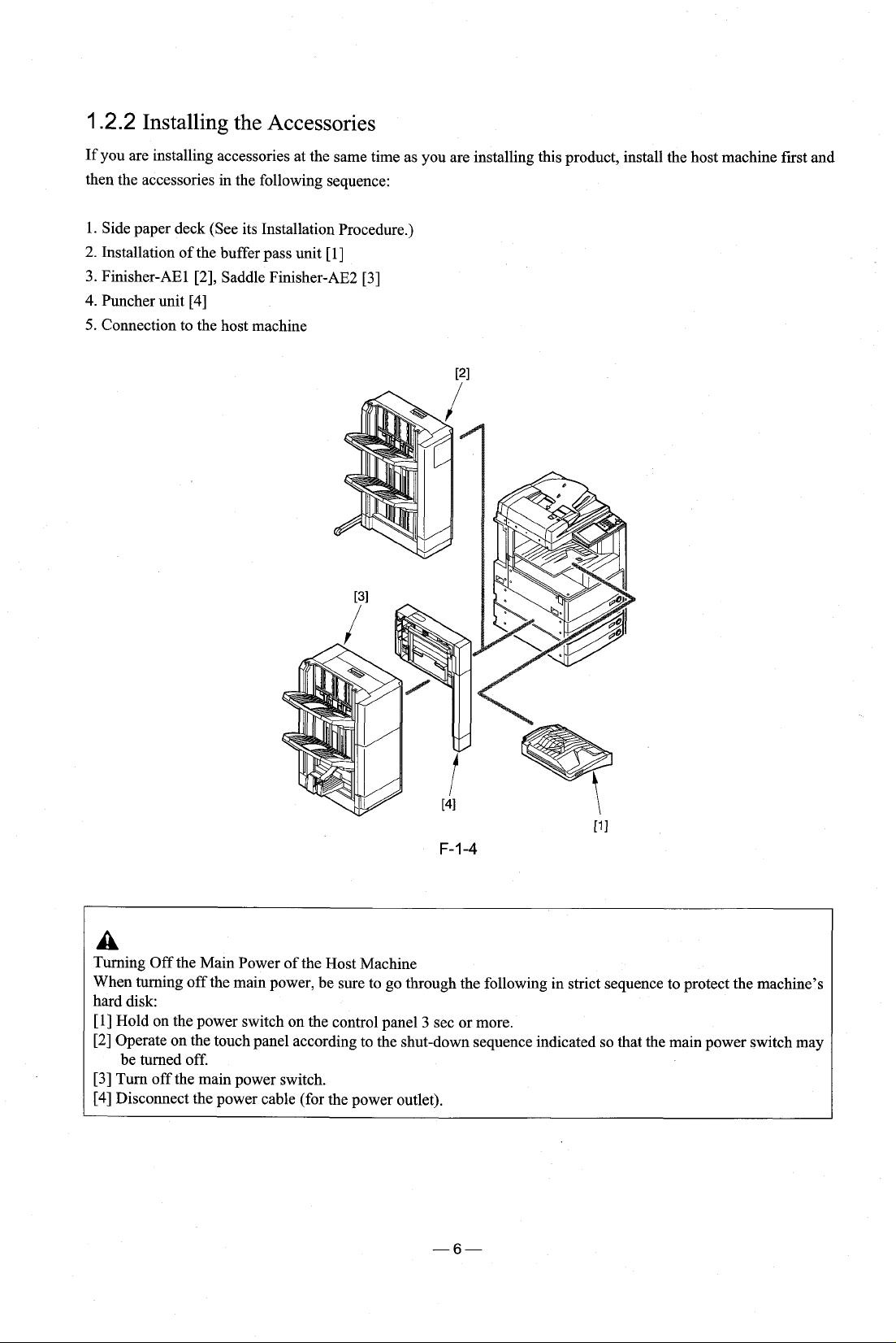
.2.2
Installing the Accessories
If you are installing accessories at the same time as you are installing this product, install the host machine first and
then the accessories in the following sequence:
1. Side paper deck (See its Installation Procedure.)
2. Installation of the buffer pass unit
3. Finisher-AE 1 [2], Saddle Finisher-AE2 [3]
4.
Puncher unit
5.
Connection to the host machine
[4]
[I]
a
Turning Off the Main Power of the Host Machine
When turning off the main power, be sure to go through the following in strict sequence to protect the machine's
hard disk:
[l]
Hold on the power switch on the control panel 3 sec or more.
[2] Operate on the touch panel according to the shut-down sequence indicated so that the main power switch may
be turned off.
[3] Turn off the main power switch.
,
[4]
Disconnect the power cable (for the power outlet).
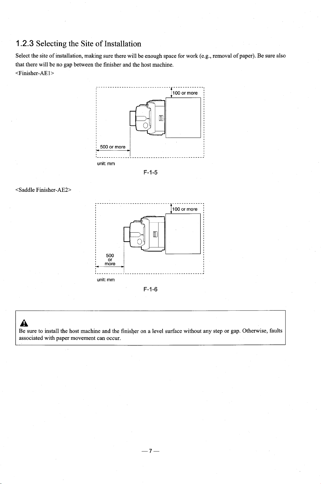
1.2.3
Select the site of installation, making sure there will be enough space for work (e.g., removal of paper). Be sure also
that there will be no gap between the finisher and the host machine.
<Finisher-AEl>
Selecting the Site of Installation
unit:
mm
F-1-5
100
or more
:
--------...
unit:
mm
!
----------------......-----------
F-1-6
:
A
Be sure to install the host machine and the finisher on a level surface without any step or gap. Otherwise, faults
associated with paper movement can occur.
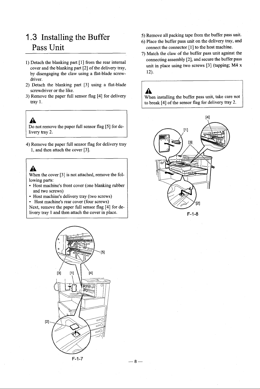
1.3
Installing the Buffer
Pass Unit
1) Detach the blanking part
cover and the blanking part [2] of the delivery tray,
by disengaging the claw using a flat-blade
driver.
2) Detach the blanking part [3] using a flat-blade
screwdriver or the like.
3) Remove the paper full sensor flag [4] for delivery
tray 1.
Do not remove the paper full sensor flag [5] for de-
livery tray 2.
4) Remove the paper full sensor flag for delivery tray
1, and then attach the cover
[I] from the rear internal
screw-
[3].
A
When the cover [3] is not attached, remove the following parts:
Host machine's front cover (one blanking rubber
and two screws)
Host machine's delivery tray (two screws)
Host machine's rear cover (four screws)
Next, remove the paper full sensor flag [4] for de-
1
livery tray
and then attach the cover in place.
5) Remove all packing tape from the buffer pass unit.
6)
Place the buffer pass unit on the delivery tray, and
connect the connector [l] to the host machine.
7)
Match the claw of the buffer pass unit against the
connecting assembly
unit in place using two screws [3] (tapping; M4 x
12).
When installing the buffer pass unit, take care not
to break
[4]
of the sensor flag for delivery tray
[2], and secure the buffer pass
2.
1.4
Unpacking and Checking
the Components
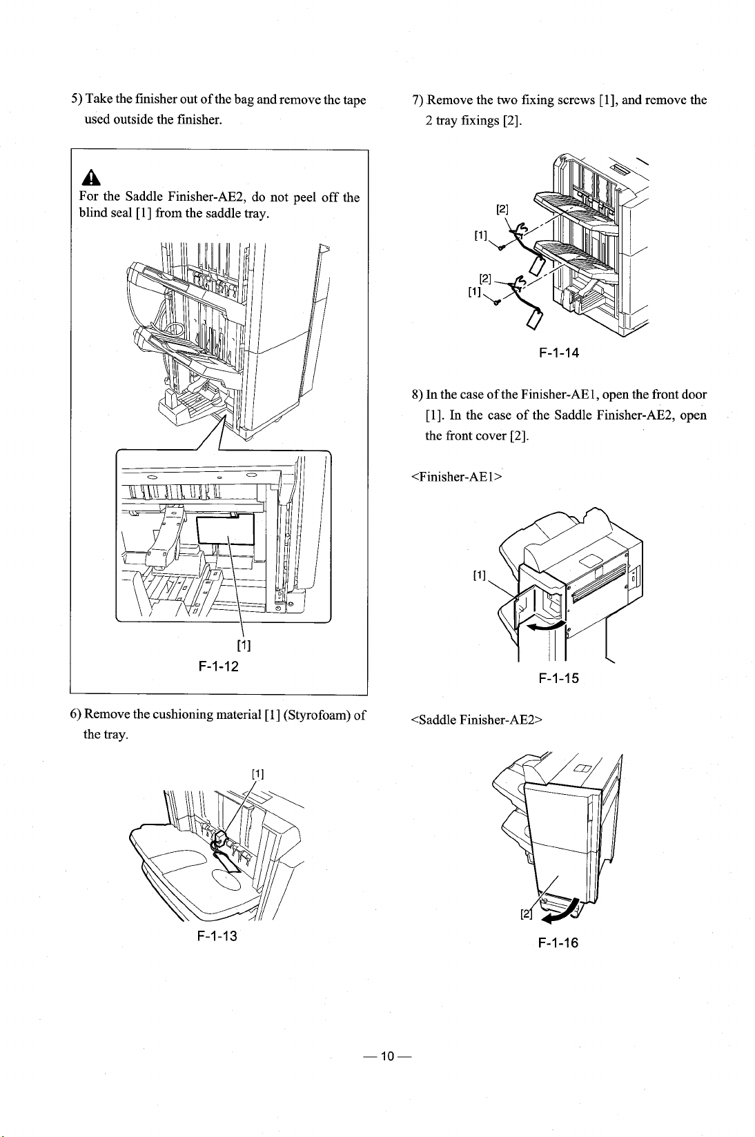
2) Lift the finisher together with its cushioning base
(Styrofoam). Be sure to work in a group of two persons.
1.4.1
1)
+
Unpacking (Finisher)
MEMO:
The machine is packed using tape and cushioning
materials to be protected against vibration and
shock during transit. Be sure to remove them before starting to install the machine. (It is a good
idea to store away the removed tape and cushioning material for possible relocation of the machine,
e.g., to a new site or for repairs.)
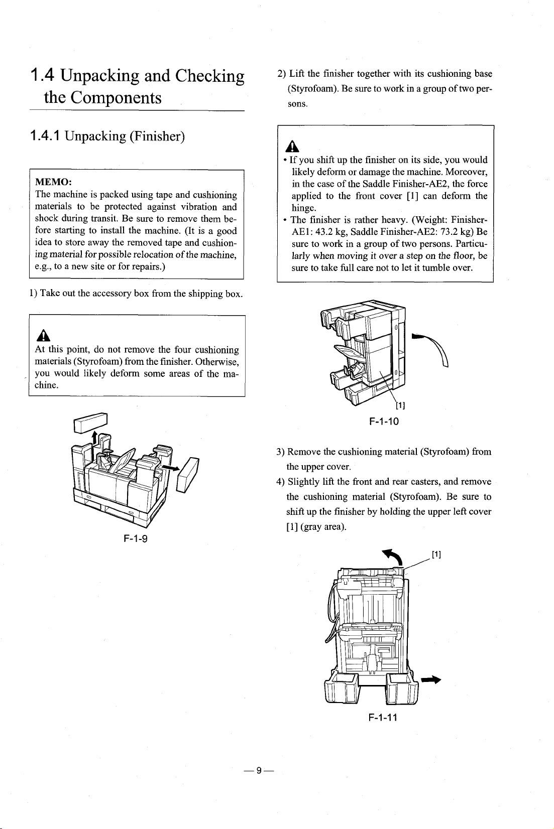
Take out the accessory box from the shipping box.
At this point, do not remove the four cushioning
materials (Styrofoam) from the finisher. Otherwise,
you would likely deform some areas of the machine.
A
If you shift up the finisher on its side, you would
likely deform or damage the machine. Moreover,
in the case of the Saddle
applied to the front cover
hinge.
The finisher is rather heavy. (Weight: Finisher-
AE1: 43.2 kg, Saddle Finisher-AE2: 73.2 kg) Be
sure to work in a group of two persons. Particularly when moving it over a step on the floor, be
sure to take
full care not to let it tumble over.
Finisher-AE2, the force
[l] can deform the
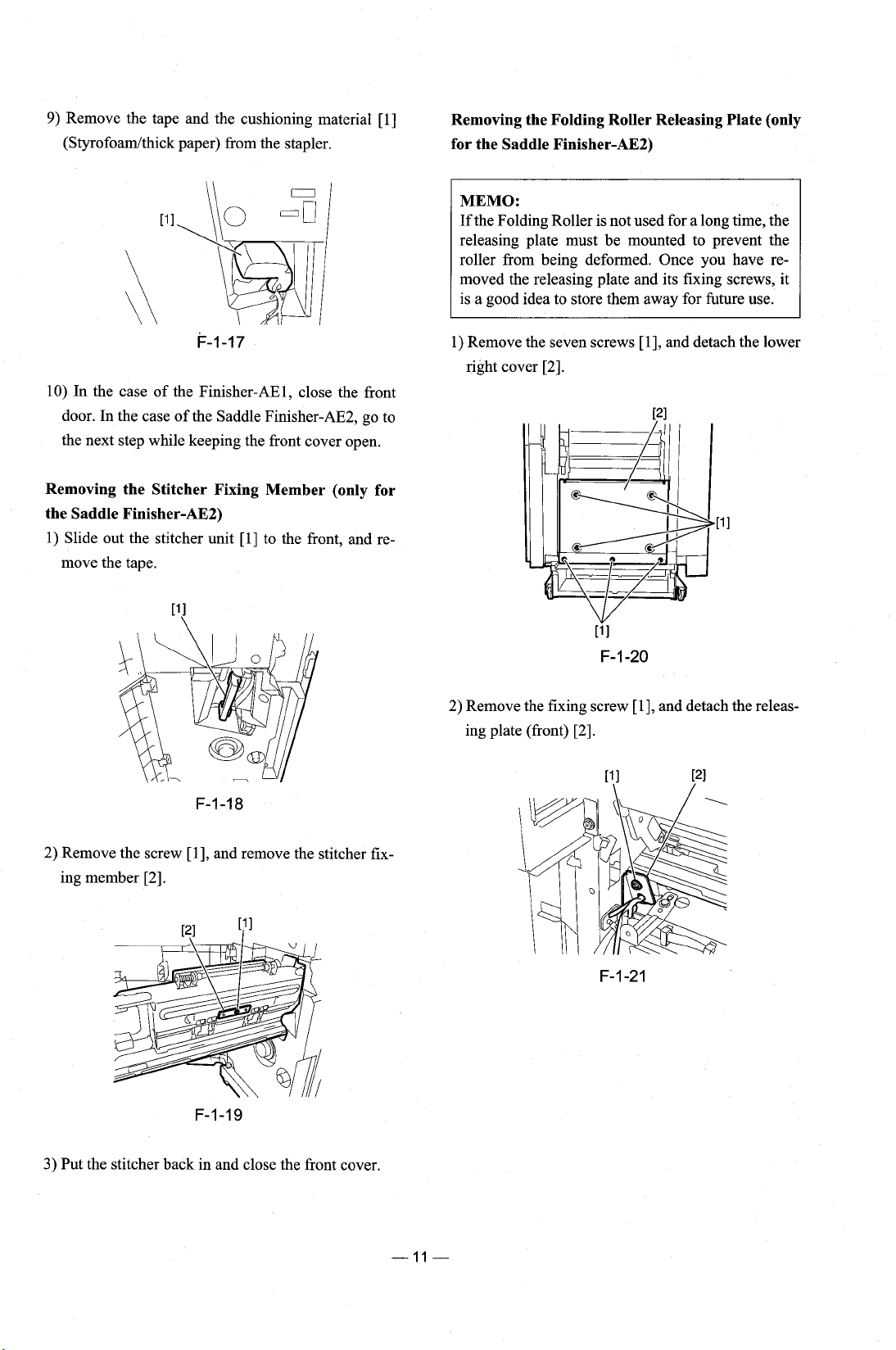
3) Remove the cushioning material (Styrofoam)
the upper cover.
4)
Slightly lift the front and rear casters, and remove
the cushioning material (Styrofoam). Be sure to
shift up the finisher by holding the upper left cover
PI
(gray area).
F-I
-1
I
from
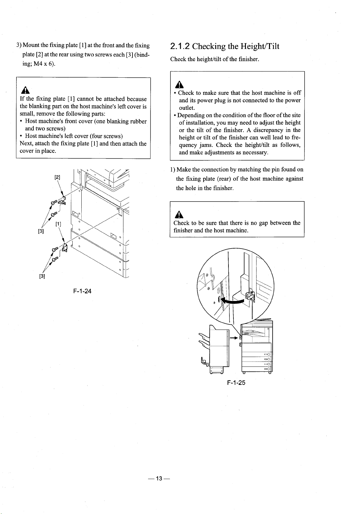
5)
Take the finisher out of the bag and remove the tape
used outside the finisher.
A
For the Saddle Finisher-AE2, do not peel off the
blind seal
[I] from the saddle tray.
7)
Remove the two fixing screws [I], and remove the
2 tray fixings
8)
In the case of the Finisher-AEl, open the front door
[I]. In the case of the Saddle Finisher-AE2, open
the front cover
[2].
[2].
[?I
F-1-12
6)
Remove the cushioning material [I] (Styrofoam) of
the tray.
<Saddle
Finisher-AE2>
9)
Remove the tape and the cushioning material [l]
(Styrofoarnlthick paper) from the stapler.
Removing the Folding Roller Releasing Plate (only
for the Saddle Finisher-AE2)
MEMO:
If the Folding Roller is not used for a long time, the
releasing plate must be mounted to prevent the
roller from being deformed. Once you have removed the releasing plate and its fixing screws, it
is a good idea to store them away for future use.
10) In the case of the Finisher-AEl, close the front
door. In the case of the Saddle Finisher-AE2, go to
the next step while keeping the front cover open.
Removing the Stitcher Fixing Member (only for
the Saddle Finisher-AE2)
1) Slide out the stitcher unit [I] to the front, and remove the tape.
1) Remove the seven screws
right cover
2)
Remove the fixing screw [I], and detach the releas-
ing plate (front)
[2].
[2].
[I], and detach the lower
2) Remove the screw
ing member
3)
Put the stitcher back in and close the front cover.
[I], and remove the stitcher fix-
[2].
F-1-19

3) Remove the fixing screw [I], and detach the releasing plate (rear) [2].
4)
Mount
the lower right cover you have removed us-
ing the
seven screws.
2.1
Installation Procedure
(When Installing Only the
Finisher)
2.1
.I
Making Preparing on the Host
Machine
Before connecting the finisher to its host machine,
mount the fixing plate to the host machine.
1) Detach the blanking covers
cover using a nipper.
2) Detach the blanking cover [3] from the left rear
cover using a nipper.
[I] and [2] from the left
3) Mount the fixing plate [I] at the front and the fixing
plate
[2]
at the rear using two screws each [3] (bind-
M4
x
ing;
6).
2.1
.2
Checking the HeightITilt
Check the heightltilt of the finisher.
A
If the fixing plate
the blanking part on the host machine's left cover is
small, remove the following parts:
Host machine's front cover (one blanking rubber
and two screws)
Host machine's left cover (four screws)
Next, attach the fixing plate
cover in place.
[I]
cannot be attached because
[l] and then attach the
A
Check to make sure that the host machine is off
and its power plug is not connected to the power
outlet.
Depending on the condition of the floor of the site
of installation, you may need to adjust the height
or the tilt of the finisher.
height or tilt of the finisher can well lead to frequency jams. Check the
and make adjustments as necessary.
1) Make the connection by matching the pin found on
the fixing plate (rear) of the host machine against
the hole in the finisher.
Check to be sure that there is no gap between the
finisher and the host machine.
A
discrepancy in the
heightltilt as follows,
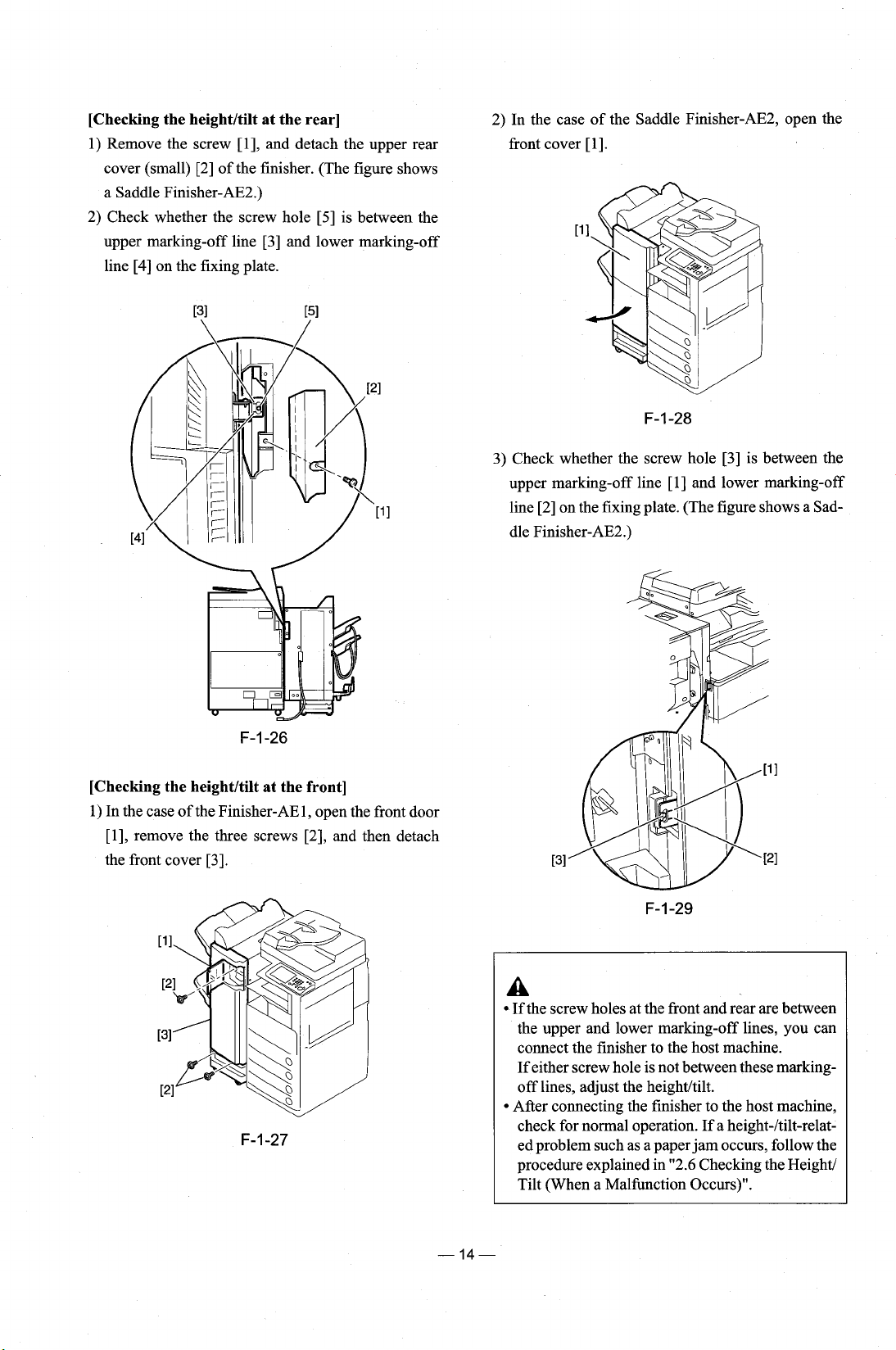
[Checking the heightltilt at the rear]
1) Remove the screw [I], and detach the upper rear
cover (small) [2] of the finisher. (The figure shows
a Saddle
2) Check whether the screw hole [5] is between the
upper marking-off line [3] and lower marking-off
line [4] on the fixing plate.
Finisher-AE2.)
2) In the case of the Saddle
front cover
3) Check whether the screw hole [3] is between the
upper marking-off line
line [2] on the fixing plate. (The figure shows a Saddle Finisher-AE2.)
[I].
Finisher-AE2, open the
[I]
and lower marking-off
[Checking the heightltilt at the front]
1) In the case of the Finisher-AE1, open the front door
[I], remove the three screws [2], and then detach
the front cover
[3].
A
If the screw holes at the front and rear are between
the upper and lower marking-off lines, you can
connect the finisher to the host machine.
If either screw hole is not between these
off lines, adjust the heightltilt.
After connecting the finisher to the host machine,
check for normal operation. If a
ed problem such as a paper jam occurs, follow the
procedure explained in "2.6 Checking the
Tilt (When a Malfunction Occurs)".
marking-
height-ltilt-relat-
Height/
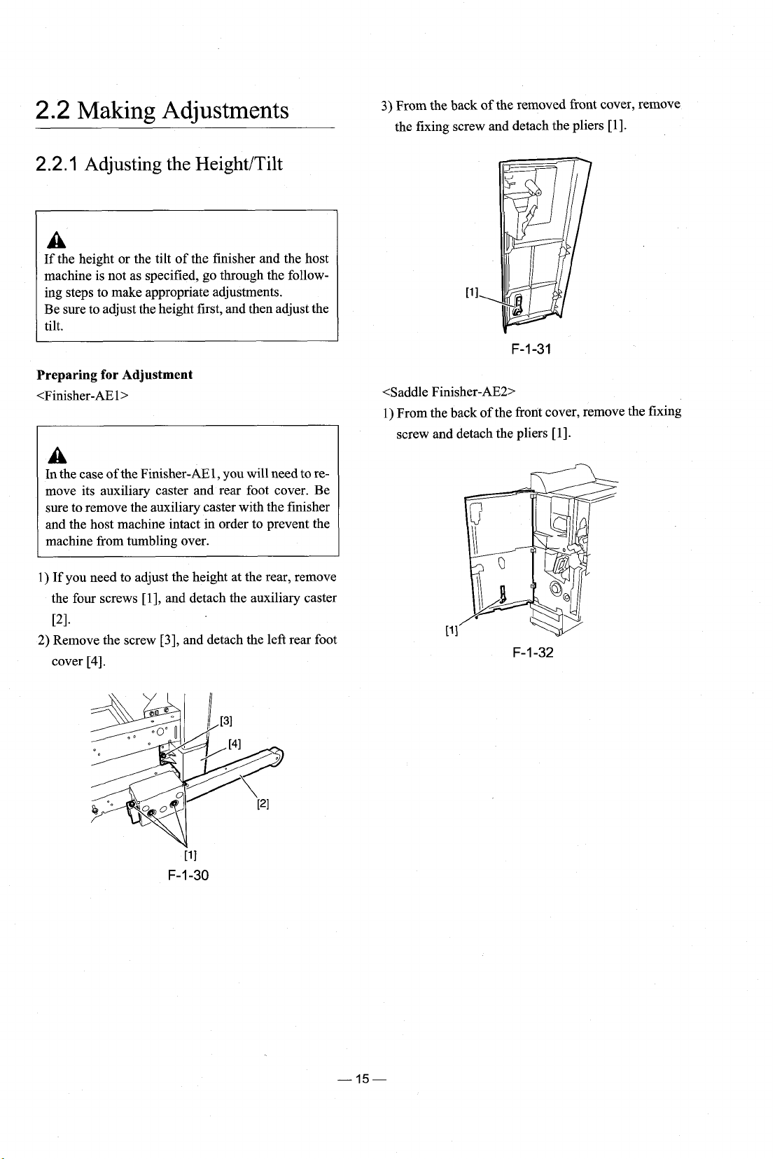
2.2
Making Adjustments
3)
From the back
the fixing screw and detach the pliers
of
the removed front cover, remove
[I].
2.2.1
Adjusting the HeightITilt
A
If
the height or the tilt of the finisher and the host
machine is not as specified, go through the following steps to make appropriate adjustments.
Be sure to adjust the height first, and then adjust the
tilt.
Preparing for Adjustment
<Finisher-AEl>
A
In the case of the Finisher-AE 1, you will need to remove its auxiliary caster and rear foot cover. Be
sure to remove the auxiliary caster with the finisher
and the host machine intact in order to prevent the
machine from tumbling over.
<Saddle Finisher-AE2>
1) From the back of the front cover, remove the fixing
screw and detach the pliers
[I].
1)
If you need to adjust the height at the rear, remove
the four screws
PI.
2)
Remove the screw
cover
[4].
[I], and detach the auxiliary caster
[3],
and detach the left rear foot
 Loading...