

Canon LV-X4U, LV-X4E, D78-5532, D78-5533 Service Manual
SERVICE MANUAL
English Edition
LV-X4U/D78-5532
LV-X4E/D78-5533
By Portable Document Format
1
General
0
PREFACE
2
Repair
3
Adjustment
4
Troubleshooting
5
Electrical Diagrams
5
Parts Catalog
6
Electrical Diagrams
DY8-1785-531 500

CANON Multimedia Projector
LV-X4U D78-5532
LV-X4E D78-5533
SERVICE
SMANUAL

Technical Documents
Application
This CD-ROM is issued by Canon Inc. for qualified persons to learn technical theory and product
repair. This CD-ROM covers all localities where the products are sold. For this reason, there
may be information in this CD-ROM that does not apply to the product sold in your locality.
The following paragraph does not apply to any countries where such provisions are
inconsistent with local law.
Trademarks
The product names and company names described in this CD-ROM are the registered
trademarks of the individual companies.
Copyright
Canon Inc. retains the copyright to all data contained on this CD-ROM. Reproduction,
publication (including on the World Wide Web) alteration, translation into another language, or
other use of the data in whole or part, contained on this CD-ROM without the written consent of
Canon Inc., is prohibited.
Copyright © 2004 by Canon Inc.
CANON INC.
30-2 Shimomaruko 3-Chome, Ohta-ku,
Tokyo 146-8501, Japan
First published November, 2004

PREFACE
1. Service Manual Composition
This manual contains information on servicing the product. It has the following
sections.
Part 1 General Information
Provides the basic information needed to understand the product.
(Operating instructions are not included. Refer to the product's instruction book if
necessary.)
Part 2 Repair Information
Provides information for disassembly, reassembly, and adjustment of the product, about
the tools required, and their application.
Part 3 Adjustment
Provides information for disassembly, reassembly, and adjustment of the product to
assure precision of the products, about the tools required, and their application.
Part 4 Troubleshooting
Part 5 Parts Catalog
Part 6 Electrical Diagrams
2. Model Differences
In this series of products, there are models suffixed "J", "U", and "E". The only
differences between the models are cosmetic, mainly the designation and rating plates.
Internally, they are identical.
The accessories bundled with the product may differ from country to country.
I
Main Marketing Area
Japan North America Europe
POWER PROJECTOR
MULTIMEDIA PROJECTOR MULTIMEDIA PROJECTOR
Model Name LV-X4J LV-X4U LV-X4E
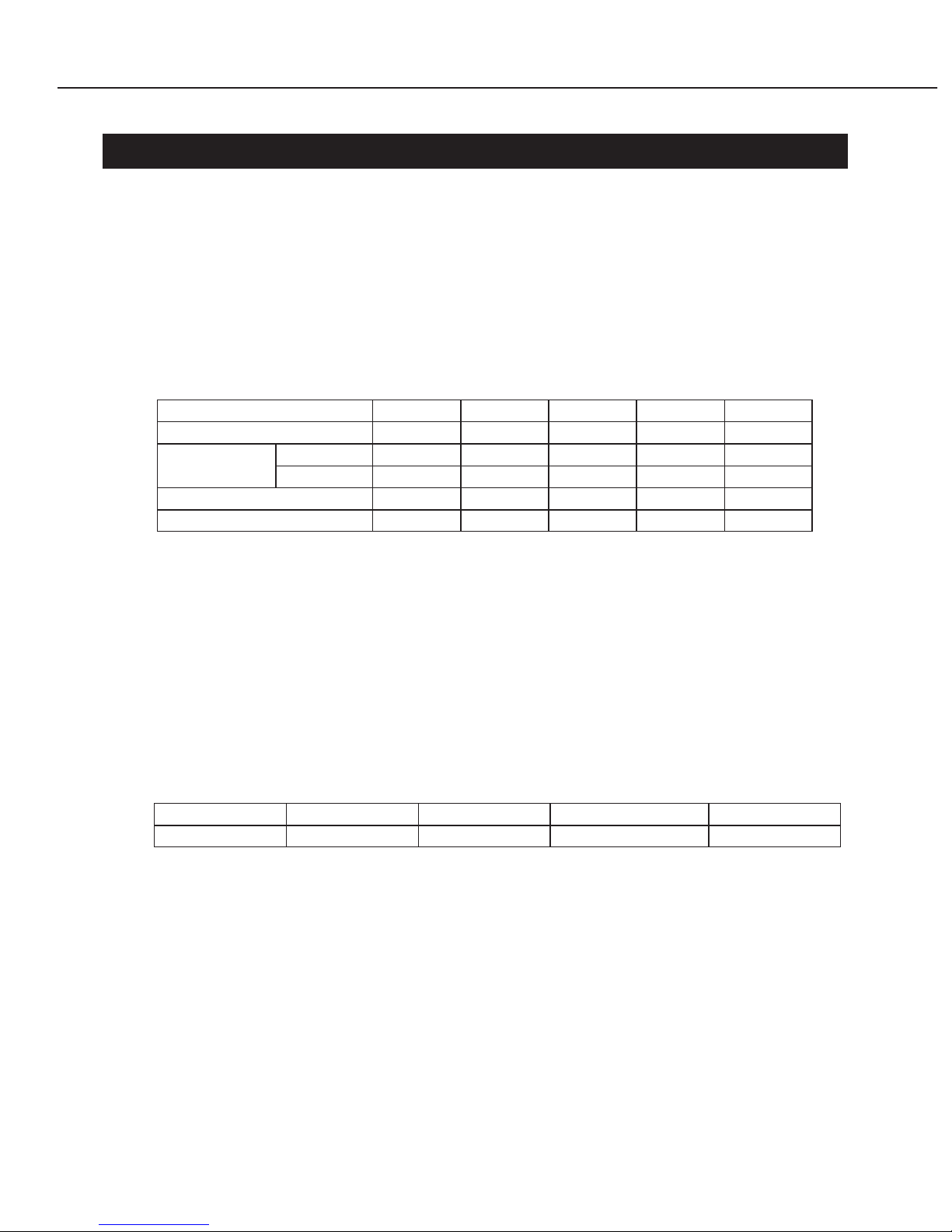
3. Tools & Test Equipment
The following tools and equipment are required to perform disassembly, reassembly
and adjustment.
1) Special Tools
None
2) General Purpose Tools (Commercially available, but can be purchased with
the following numbers.)
3) Test Equipment
4) Other Equipment
5) Chart/Software
II
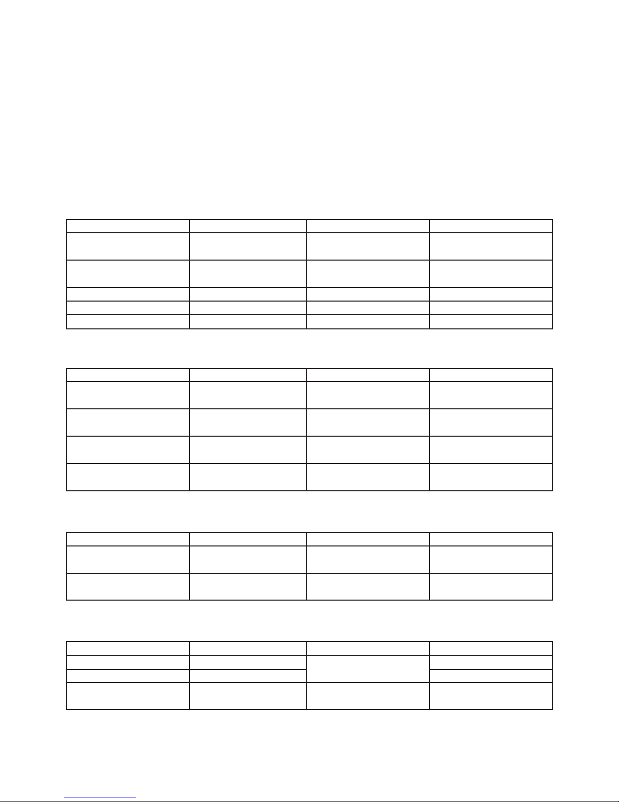
Description Tool No. Specification Remarks
Ball Driver CY9-5002-000 2.0mm Optical Parts Removal
& Adjustment
Hex Key Set CY9-5007-000 2.0mm Optical Parts Removal
& Adjustment
Driver, adjustment CY9-5003-000 1.8mm Electrical Adjustments
Driver, Slot CY9-5004-000 4.0mm
Optical Parts Adjustment
Driver, Cross-point CY9-5005-000 No.2 A
ssembly & Disassembly
Description Tool No. Specification Remarks
Digital Multi-meter Commercially DC1mmV~500V Electrical Adjustment
available
Video Signal Generator
Commercially Color Bars and Gray
Electrical Adjustment
available Scale
Computer Signal Commercially Gray Scale
Electrical Adjustment
Generator available (or personal computer)
Oscilloscope
Commercially 100MHz response or Waveform Checks and
available over Electrical Adjustment
Description Tool No. Specification Remarks
Screen
Commercially Over 40"
All Adjustment
available
Personal Computer
Commercially
Windows 98/2000 OS All
Adjustment
available
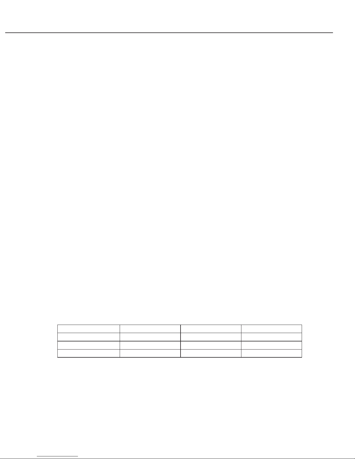
Description Tool No. Specification Remarks
Monitor Tester Supplied with manual Bitmap Data All Adjustment
Gray Scale Chart Supplied with manual (XGA and SVGA) All Adjustment
Color Shading
Supplied with manual Ver. 3.03
White Uniformity
Correction Tool Adjustment

CONTENTS
Page
Part 1: General Information
1. PRODUCT OVERVIEW ................................................................................... 1-1
2. MAIN FEATURES ............................................................................................ 1-2
3. SPECIFICATIONS ........................................................................................... 1-3
3.1 Type ......................................................................................................... 1-3
3.2 LCD panel ................................................................................................ 1-3
3.3 Optics ....................................................................................................... 1-3
3.4 Images ..................................................................................................... 1-3
3.5 Image signals ........................................................................................... 1-3
3.6 Mechanisms ............................................................................................. 1-3
3.7 Terminals ................................................................................................. 1-4
3.8 Ratings ..................................................................................................... 1-4
4. FUNCTIONS .................................................................................................... 1-5
4.1 Optics ....................................................................................................... 1-5
4.2 Images ..................................................................................................... 1-5
4.3 Image signals ........................................................................................... 1-7
4.4 Mechanisms and systems ....................................................................... 1-8
5. TERMINALS .................................................................................................... 1-10
5.1 Rear Panel ............................................................................................... 1-10
5.2 Configurations of terminals ...................................................................... 1-11
6. ACCESSORIES ............................................................................................... 1-12
6.1 Principal accessories ............................................................................... 1-12
6.2 Replacement parts ................................................................................... 1-12
6.3 Optional parts .......................................................................................... 1-12
7. PRECAUTIONS FOR USE .............................................................................. 1-13
8. DESCRIPTION ................................................................................................ 1-14
8.1 Optics ....................................................................................................... 1-14
8.2 Images ..................................................................................................... 1-14
8.3 Image signals ........................................................................................... 1-15
8.4 Mechanisms and Systems ....................................................................... 1-15
8.5 Design ...................................................................................................... 1-15
Part 2: Repair Information
1. SAFETY INSTRUCTIONS ............................................................................... 2-1
2. CIRCUIT PROTECTIONS ............................................................................... 2-2
2.1 Fuse ......................................................................................................... 2-2
2.2 Thermal Switch ........................................................................................ 2-2
2.3 Lamp Cover Switch .................................................................................. 2-2
2.4 Warning Temperature and Power Failure Protection .............................. 2-3
2.5 Air Filter Care and Cleaning .................................................................... 2-3
3. MECHANICAL DISASSEMBLIES .................................................................... 2-5
III

3.1 Cabinet Top, FN901 Removal ................................................................. 2-5
3.2 Cabinet Front, R/C Board, FN902, SP901 Removal ............................... 2-6
3.3 Main Board Removal ............................................................................... 2-6
3.4 Rear Panel and AV Board Removal ........................................................ 2-7
3.5 Optical Unit Removal ............................................................................... 2-7
3.6 Power, Lamp Ballast, Lamp Cover SW Board Removal .......................... 2-8
3.7 Fans Removal .......................................................................................... 2-8
4. OPTICAL PARTS DISASSEMBLIES ............................................................... 2-9
4.1 Projection Lens Removal ......................................................................... 2-9
4.2 Integrator Lens-In Disassembly ............................................................... 2-9
4.3 Relay Lens-Out Disassembly .................................................................. 2-10
4.4 Polarized Glass-In Removal .................................................................... 2-10
4.5 LCD Panel/Prism Ass’y Removal ............................................................. 2-11
4.6 Polarized Glasses-Out Removal............................................................... 2-12
4.7 Optical Unit Top Removal ........................................................................ 2-12
4.8 Locations and Directions ......................................................................... 2-13
5. CLEANING ....................................................................................................... 2-14
6. LAMP REPLACEMENT ................................................................................... 2-15
Part 3: Adjustment
1. ADJUSTMENT ................................................................................................. 3-1
1.1 Adjustments after Parts Replacement ..................................................... 3-1
1.2 Service Adjustment Menu Operation ....................................................... 3-2
1.3 Service Adjustment Data Table ............................................................... 3-3
2. CIRCUIT ADJUSTMENTS ............................................................................... 3-8
2.1 Output Voltage Adjustment ...................................................................... 3-8
2.2 Fan Control Adjustment ........................................................................... 3-9
2.3 Pedestal Adjustment [PC] ........................................................................ 3-9
2.4 Pedestal Adjustment [Component] .......................................................... 3-10
2.5 Gain Adjustment [PC] .............................................................................. 3-10
2.6 Gain Adjustment [AV-Video] .................................................................... 3-11
2.7 Gain Adjustment [Component] ................................................................. 3-11
2.8 Video Center Adjustment ......................................................................... 3-12
2.9 Black Reference Adjustment ................................................................... 3-12
2.10 Common Center Adjustment ................................................................. 3-13
2.11 Gamma Adjustment ............................................................................... 3-13
2.12 White Balance Adjustment ..................................................................... 3-14
2.13 Note On White Uniformity Adjustment ................................................... 3-14
3. OPTICAL ADJUSTMENTS .............................................................................. 3-15
3.1 Contrast Adjustment ................................................................................ 3-15
3.2 Integrator Lens Adjustment ...................................................................... 3-16
3.3 Relay Lens-Out Adjustment ..................................................................... 3-17
4. TEST POINTS AND LOCATIONS ................................................................... 3-18
IV

Part 4: Troubleshooting
1. TROUBLESHOOTING ..................................................................................... 4-1
1.1 Indicators and Projector Condition ........................................................... 4-1
1.2 No Power ................................................................................................. 4-2
1.3 Power Control Timing Chart ..................................................................... 4-5
1.4 No Picture ................................................................................................ 4-7
1.5 No Sound ................................................................................................. 4-9
2. CONTROL PORT FUNCTIONS ...................................................................... 4-10
2.1 System Control & I/O Port Table (IC301) ................................................ 4-10
2.2 IIC Bus D/A Converter (IC3531, M62398FP) Port Functions .................. 4-11
2.3 IIC Bus D/A Converter (IC7961, M62393FP) Port Functions .................. 4-12
2.4 Output Expander (IC1801, TC74LCX574FT) Port Functions .................. 4-12
2.5 Output Expander (IC1802, TC74LCX574FT) Port Functions .................. 4-12
2.6 Output Expander (IC1803, TC74LCX574FT) Port Functions ................... 4-13
2.7 Output Expander (IC1804, TC74LCX574FT) Port Functions ................... 4-13
2.8 LAMP CPU (IC4811, PIC16F88) Port Functions ...................................... 4-13
3. WAVEFORM .................................................................................................... 4-14
4. IC BLOCK DIAGRAMS .................................................................................... 4-15
Part 5: Parts Catalog
Part 6: Electrical Diagrams
1. PARTS DESCRIPTION AND READING IN SCHEMATIC DIAGRAM.............. 6-1
2. DIODE, TRANSISTOR AND IC PINS............................................................... 6-3
Chassis Block Diagrams ................................................................................... 6-4
Schematic Diagrams ......................................................................................... A3
Printed Wiring Board Diagrams......................................................................... A9
V

Part 1
General
Information
1. PRODUCT OVERVIEW
With 1500 lm brightness, XGA resolution, and weight of 2.9 kg, this projector is in the
micro-portable class.
It features the highest zoom ratio for its class (1.6×), the ratio that has had proven
results in the standard series. Above projection lens enables 100-inch projection from
only 2.5m away.
Equipped with image input and system functions actualized in a part of the models
launched after the LV-X2, such as 2-3 pull-down, this model also has new features
including blackboard mode and security functions that have been incorporated for the
first time ever in a Canon projector.
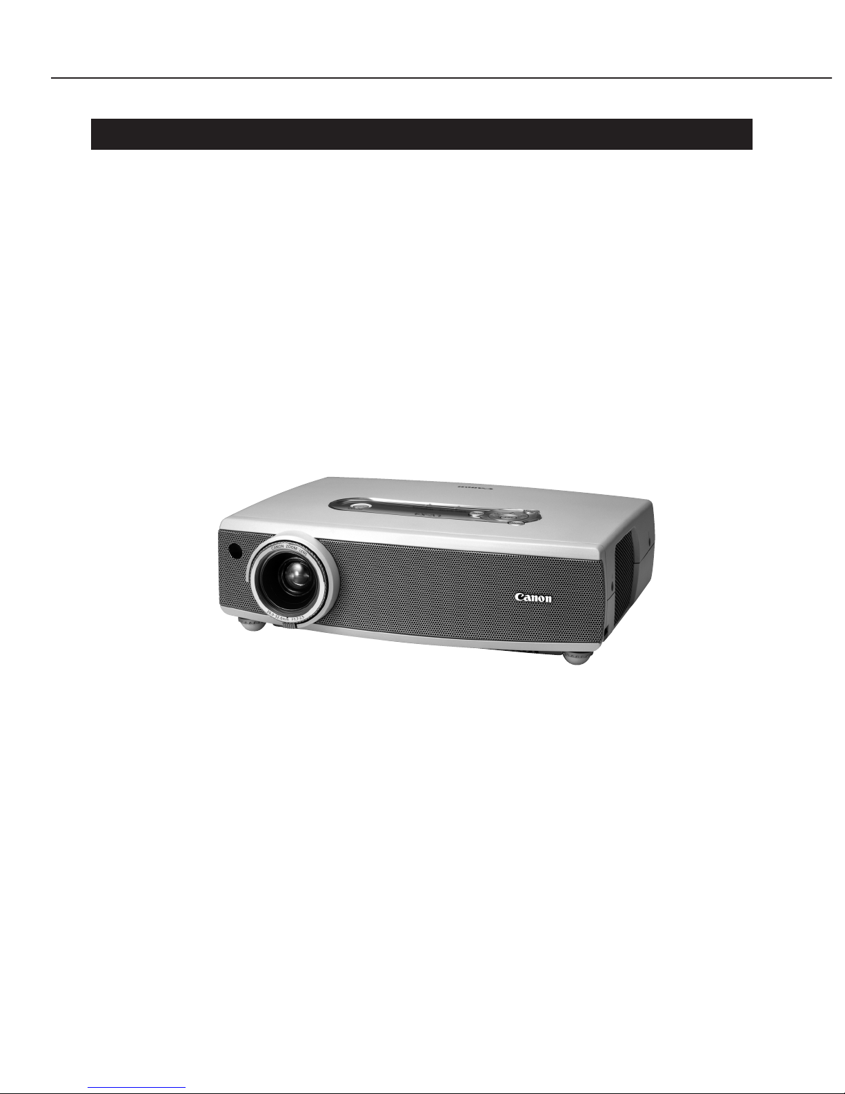
Fig. 1-1 Exterior of LV-X4
Part 1: General Information
1-1

2. MAIN FEATURES
● XGA and achieving 1500 lm
A 200 W SHP lamp has been adopted. The projector is compact and lightweight
(micro-portable), and XGA achieves a bright display of 1500 lm.
● A4-file size, 2.9 kg
With the compact body achieved through space-saving design, we were able to reduce
projector weight to 2.9kg. Together with the color, Frosty White Pearl, this gives the
projector a feeling of quality and lightness.
● 1.6x wide zoom lens (highest zoom ratio for its class) projecting 100 inches at 2.5 m
The compact wide zoom lens, with its proven results, utilizes two aspherical lenses
(one on each end) and one UD lens with anomalous dispersion characteristics.
Having the highest zoom ratio in its class, 1.6×, and the lens not only enables 100-
inch, large-screen projection from only 2.5m away but also produces high-quality
images with color bleeding curbed.
● Accommodates 2-3 pull-down (480i)
When there is 480i component signal and NTSC composite signal input, this function
automatically identifies input signals that have been converted from Cinema to
television image signals and faithfully converts them to progressive display.
● Blackboard mode
Added to the conventional image mode, this new mode was created for projection on
blackboards (in green). Mere selection of the dedicated video reproduction mode
makes it possible to approximate natural color tone.
● Security function
Setting a password makes it possible to institute usage restriction.
When this function is used, the password will be required when starting up the
projector and modifying the startup logo.
● Lamp modes
These products come with three lamp modes — Normal, Silent, and Auto — that allow
users to switch the lamp's brightness.
The Normal Mode prioritizes brightness, the Silent Mode runs quietly at 35 dB by
lowering the fan speed, and the Auto Mode improves the reproduction of black by
adjusting the lamp's output to suit the scene.
● Fan setting when power is off
Cooling fan operation when power is off can be set to high-speed revolution (for 90 sec)
or standard revolution (for 120 sec). With standard revolution, fan noise will not
become loud when the lamp is off, which is convenient in many cases, such as when
continuing a meeting with the lamp off.
Part 1: General Information
1-2

3. SPECIFICATIONS
3.1 Type
1. Product type Projector
2. Product class Micro Portable class
3. Imaging device Transmitting LCD panel
3.2 LCD panel
1. Number of pixels 1024 × 768 (XGA)
2. Size and number 16 × 12 mm (0.8", 4:3 aspect ratio), 3 panels
3. Micro-lens Not Attached
4. Drive system TFT active matrix
3.3 Optics
1. System Dichroic mirror separation and cross-prism
combination system
2. Light source 200W-SHP (Normal: 190 W/Silent: 168 W)
3. Projection lens configuration 11 groups of 11 elements
4. F number and focal length F1.7 - 2.5, f=20.3 - 32.5 mm
5. Zoom, Focus 1.6 times manual zooming, manual focusing
6. Lens shift 9:1, fixed
3.4 Images
1. Brightness 1500 lm (at Normal mode)
2. Marginal lumination ratio 90%
3. Contrast ratio 400:1 (100% white to 0% black)
4. Projection distance coverage 1.0 - 7.7 m (100" at 2.5 m - 4.0 m)
5. Screen size 40" (81 × 61 cm) - 300" (610 × 457 cm)
6. Electronic zoom ×0.5 - ×16
7. Keystone correction range ±20 degrees in up/down direction
3.5 Image signals
1. Analog RGB/Digital RGB SXGA/XGA/SVGA/VGA
2. Composite NTSC/PAL/SECAM/NTSC4.43/PAL-M/PAL-N
3. Component 1080i/1035i/720p/575p/575i/480p/480i
4. Scanning frequency (H) 15 - 100 kHz
5. Scanning frequency (V) 50 - 100 Hz
6. Dot clock 130 MHz
3.6 Mechanisms
1. Adjustable feet 11.9° maximum (To raise the projector)
2. Built-in speaker 1 W, Monaural
Part 1: General Information
1-3
3.7 Terminals
1. Mini D-sub15 pin (1) Analog RGB input/Component input/SCART input
2. Mini D-sub15 pin (2) Analog RGB input/Analog RGB output
3. RCA ×1 Composite input
4. S-video terminal
(Mini DIN 4 pin)
S-Video input
5. Stereo mini-jack (in) Audio input
6. RCA ×2 Audio input
7. Stereo mini-jack (out) Audio output
8. USB terminal (type B) Mouse control port
9. Service port (Mini DIN 8 pin) Connector used for servicing the projector
3.8 Ratings
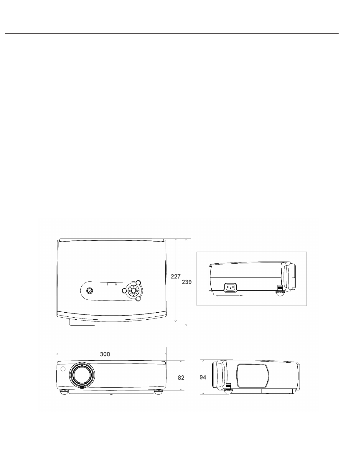
1. Dimensions W: 300 mm, D: 227 mm, H: 82 mm (See Outline
Drawings)
2. Mass 2.9 kg
3. Rated supply voltage AC100 - 240 V; 50/60 Hz
4. Power consumption Normal: 260 W/Silent: 230 W/Stand-by: 7 W
5. Noise Normal: 39 dB/Silent: 35 dB
6. Ambient temperature range 5 - 35°C
7. Storage temperature range –10 - 60°C
Fig. 1-2 Outline Drawings of LV-X4
Part 1: General Information
1-4
4. FUNCTIONS
4.1 Optics
● Zoom/Focus
This projector has a projection lens with a 1.6× zoom ratio.
Zoom and focus are adjusted manually.
● Projection distance and projection screen size
These products are capable of projecting accurately at distances between 1.0 and 7.7
meters.
Note that the displayable screen size ranges from 40 to 300 inches.
* The quantities H1 and H2 represent heights of the top section and bottom section of the
screen if the screen is divided vertically along a line level with the projector's lens axis. The
ratio of H1 to H2 is 9:1.
4.2 Images
● Image mode selection (by remote control)
This function selects the optimum gamma characteristic for the relevant video
content, by signal type.
The video modes shown in the table below are available.
This projector is equipped with blackboard mode, which is completely new.
• Standard (for computer and video input)
This setting works with general.
• High contrast (for computer input)
This mode brightens mid-range areas making the overall image appear brighter.
The High-contrast Mode can reproduce low-range arias clearly even in brightly lit
environments.
• Cinema (for video input)
This mode boosts dark areas, improving the reproduction of dark pictures.
In effect, this improves the expressiveness of scenes with many dark areas,
common in movies, by preventing black saturation.
Part 1: General Information
1-5
0.81 × 0.61 2.03 × 1.52 3.05 × 2.29 3.86 × 2.90 6.10 × 4.57
1.00 2.54 3.82 4.85 7.68
1.59 4.02 6.04 7.66 –
55 137 206 261 411
6 15 23 29 46
Size [m]
Zoom min
Zoom max
Projection
Distance [m]
Screen 40" 100"
150" 190" 300"
H1 [cm]
H2 [cm]
Computer input Standard High contrast Blackboard (Green)
Video input Standard Cinema Blackboard (Green)
Custom
Custom

• Blackboard (Green)
This is the optimum mode for projecting on blackboards (green).
The intensity of the green light has been made relatively low. (Thus, the total
amount of light is also low.)
• Custom
In this mode, users can make various video adjustments, based on one of the
previous modes, to suit their personal preferences. Users can also store their
Custom Mode settings.
● Keystone correction
Keystone correction is a function that digitally compensates for deformations in the
picture shape caused by the placement of the projector. This compensation is
adjustable ±20 degrees vertically.
● Progressive display
This function automatically converts inputs of interlaced VCR signals into progressive
scans. Progressive display supports composite signals, S-video signals, and 480i and
575i component signals. Off, L1 (for moving images), and L2 (for still images) can be
selected.
● Accommodates 2-3 pull-down (480i)
When there is 480i component signal and NTSC composite signal input, this function
automatically identifies input signals that have been converted from Cinema to
television image signals and faithfully converts them to progressive display.
To set this function, select [Film] from the menu, then select [On].
● Start-up screen customization (logo, capture)
This function allows users to select a still image as the start-up screen.
Users can capture an image during projection and use that image as the start-up
screen.
● Digital zoom
This function digitally scales a selected region of the picture.
The region can be projected at anywhere between 0.5 and 16 times its normal size.
● Freeze
This function temporarily pauses an image projection.
● No show
This function temporarily shuts off the image projection.
● Presentation timer
This function displays the elapsed time as a counter on the image.
● Blue back display
This function automatically displays a solid-blue background when there is no input
signal.
Part 1: General Information
1-6

● Reverse image
This function allows the projected image to be reversed horizontally or vertically.
When rear projection is selected, the projector projects images reversed horizontally.
(Line-symmetry)
When ceiling mount is selected, the projector projects images reversed both
horizontally and vertically. (Point-symmetry)
4.3 Image signals
● Computer input
These products support several analog signal of computer display.
The details of a computer display are omitted here, but some computer display cannot
be used due to the frequency of the input signal or the type of computer. (See the owner's
manual for details)
• Analog RGB
Display resolutions: SXGA (compressed), XGA, SVGA, VGA, MAC
• Multi-scan system
The projector recognizes the horizontal and vertical frequencies of the image signal
from the connected computer and automatically selects the corresponding display
system.
• Automatic PC adjustment
This function can be set to automatically adjust the number of horizontal pixels,
tracking, and screen position of the picture.
● Component video input
• Scanning systems
These products support 1080i, 1035i, 720p, 575p, 575i, 480p and 480i. (Auto and
manual selection)
● Composite video input or S-Video input
• Color systems
These products support NTSC, PAL, SECAM, NTSC 4.43, PAL-M, and PAL-N.
Except for PAL-M and PAL-N, the projector automatically selects the color system
when the color system is set to Auto.
● SCART input (use the optional cable LV-CA31)
The analog RGB input terminal (D-sub 15 pin) has ability to input the image signal
from the SCART terminal of video apparatus.
● Image signal output - analog RGB
This projector is equipped with two D-sub 15 pin terminals, only one of which can be
used as an analog RGB output terminal. Serial connection of two projectors makes it
possible to display output from the same video source and the like.
Part 1: General Information
1-7
4.4 Mechanisms and systems
● Security Settings
1) Logo PIN Code Lock
When this function is on, [Logo] and [Capture] can no longer be selected from the
menu. A PIN code is also required in order to switch this function off.
Therefore, you must enter the PIN code with the function on to use [Logo] or
[Capture] and switch this function off.
2) PIN Code Lock
When this function is used, a code number is required to start the projector.
There are two settings, [On 1] and [On 2]; [On 1] requires the PIN code every time
the projector is started and [On 2] requires the PIN code only when the power
supply cable is disconnected.
● Key Lock Setting
There are three possible selections with this function.
(1) Always accepting the operation input
(2) Ignoring input from the operation panel
(3) Ignoring input from the remote control
● Fan setting when power is off
Cooling fan operation when power is off can be selected as follows.
L1: High-speed revolution; 90 sec (conventional operation mode)
L2: Standard revolution; 120 sec
When the projector is shipped from the factory, the fan setting will be L1. If fan noise
is distracting when the lamp is off, change the setting to L2.
● On start
This function starts the projector when the power supply cable is plugged into the
projector.
Select [On Start] from the menu, then select [On] or [Off].
● Lamp mode selection
This function selects the power consumption of the lamp.
* The lamp is rated at 200 watts; however, the output under actual operating conditions is
related to the amount of heat generated.
Part 1: General Information
1-8
MODE Normal Silent Auto
LAMP POWER 190 W 168 W Fluctuate
Noise 38 dB 36 dB Fluctuate
Brightness 1500 lm 1275 lm Fluctuate

The Normal Mode is used to project with brightness priority. The Normal Mode is
appropriate for large meeting rooms or in situations where the room cannot be
darkened.
The Silent Mode lowers the noise level by reducing the brightness. The Silent Mode is
appropriate for small screens or in situations where lower light output is sufficient.
The Auto Mode automatically varies the output of the light source. The Auto Mode
adjusts the lamp's output according to the brightness of the scene. The Auto Mode
reproduces dark scenes in a movie with an emphasis on the black component.
● Audio Mute
This function temporarily turns off the output to the speaker.
* The projectors have a built-in 1-watt speaker. Audio from computers or VCRs is
played back in monaural.
● Adjustable feet
These products come with two adjustable feet at the front heel of the unit under the
projection lens side to tilt the unit. By adjusting these feet's height, the slant of the
projection can be changed easily. The projection axis can be slanted as much as 11.9
degrees from the surface the projector is placed on.
With one movement, the adjustable foot can be unlocked and stored inside the
projector body.
* Distortions in the picture's shape when the projector is tilted can be corrected using
the previously mentioned keystone correction function.
● Power management
This function turns the lamp off if no video signal is input or projector operation
performed for a preset period.
This duration can be set between one and 30 minutes.
When the lamp has been turned off with power management, it will automatically
turn on when a video signal is input again or a projector operation performed. (Note
that the lamp will not turn on during the cool down period effective immediately after
being turned off.)
* If you select [Ready], this only switches off the lamp, and if you select [Shutdown]
this switches off the power.
● Graphical user interface
The graphical user interface allows users to make adjustments easily while watching
the display on the screen.
* The display language can be selected from one of 12 languages (English, German,
French, Spanish, Italian, Portuguese, Dutch, Swedish, Chinese, Korean, Russian,
and Japanese).
Part 1: General Information
1-9
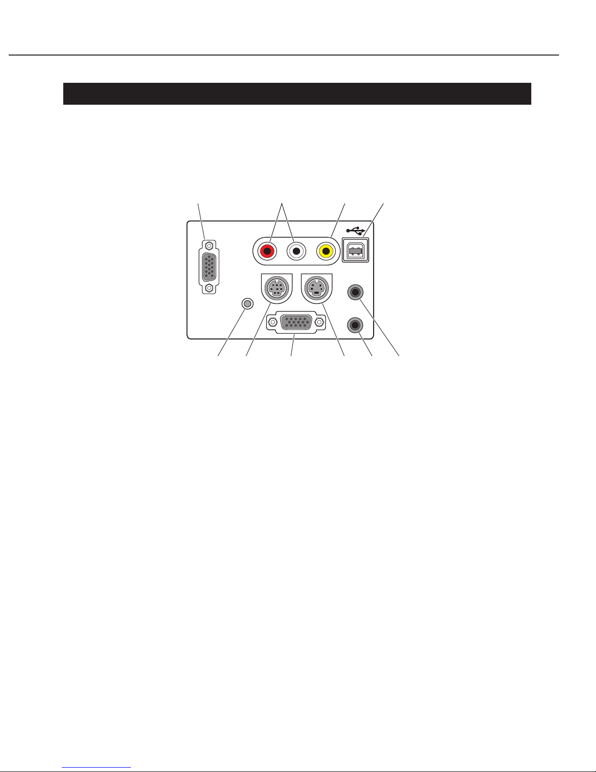
5. TERMINALS
5.1 Rear Panel
The inputs, outputs, and other connectors are located on the back of the projector.
● Image input
[1] Mini D-sub (HDB) 15 pin (1) Analog RGB, SCART, Component video
[2] Mini D-sub 15 pin (2) Analog RGB
[3] RCA ×1 Composite video
[4]
S-video connector (Mini DIN 4 pin)
S-video
● Audio input
[5] Mini pin-jack (in) Stereo (for Image inputs [1] and [2])
[6] RCA ×2 Stereo (for Image inputs [3] and [4])
* The built-in speaker provides only monaural
output.
● Output
[2]
Mini D-sub 15 pin (dual purpose)
Analog RGB
[7] Mini-pin jack (out) Stereo
● Control
[8] USB connector (Series B) USB port
[9]
Service connector (Mini DIN 8 pin)
Connector used for servicing the projector
● Others
[10] Reset button Used to restart the projector when its operation
becomes unstable
Part 1: General Information
1-10
SERVICE PORT
S-VIDEO IN
COMPUTER
AUDIO IN
AUDIO OUT
RGB IN-2/
RGB OUT
RESET
RGB IN-1/
COMPONENT IN
AUDIO
INR L VIDEO IN
1638
10 9 2 4 7
5
Fig. 1-3 Terminals
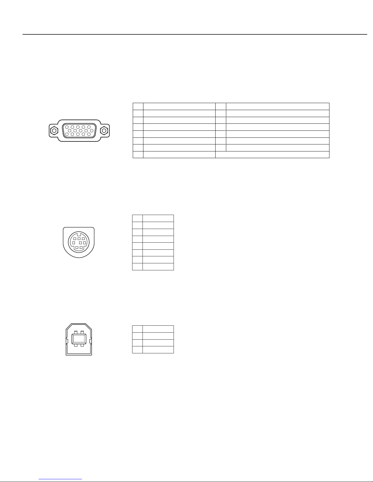
5.2 Configurations of terminals
● Mini D-sub 15 pin (HDB15 pin)
● Service Port (Mini DIN 8 pin)
● USB series B
Part 1: General Information
1-11
1
2
3
4
5
6
7
8
9
10
11
12
13
14
15
Red (R/Cr) Input / Output
Ground (H sync.)
Green (G/Y) Input / Output
-----
Blue (B/Cb) Input / Output
Ground (Red)
Ground (Green)
Ground (Blue)
-----
H sync. Input / Output (Composit H/V sync)
Ground (V sync.)
-----
Ground / -----
V sync. Input / Output
-----
51
234
10
9678
15 14 13 1112
RXD
-----
-----
GND
RTS / CTS
TXD
GND
GND
1
2
3
4
5
6
7
8
1
2
3
4
5
8 7 6
Vcc
- Data
+ Data
Ground
1
2
3
4
2
34
1
Fig. 1-4 Configurations of terminals

6. ACCESSORIES
6.1 Principal accessories
● Remote control unit
Equipped with functions to display the pointer icon onscreen and control the projector
via pushbuttons.
• Power supply 3.0 DC V; uses two AA alkaline batteries (included)
• Communication range Approx. 5 m (within ±30 degrees of the receiver)
• Dimensions 50 × 181 × 27 mm
• Weight: 154 g
● VGA cable (D-sub15 - D-sub15)
This cable is used to input analog RGB video signals from computers and other
devices.
● USB cable
6.2 Replacement parts
● Replacement lamp: LV-LP21
An indicator will light when the lamp should be replaced.
* This time guarantees a 50 percent survival rate and a 40 percent brightness-maintenance
rate.
6.3 Optional parts
● SCART cable (SCART 21 - D-sub 15): LV-CA31
● 3RCA - Dsub15 cable: LV-CA32
● Ceiling attachment: LV-CL08
This mounting bracket is used to hang the projector from a ceiling.
* Consult a building professional before attempting to mount the projector to a ceiling.
Part 1: General Information
1-12
Normal mode Silent mode
2000 hours 3000 hours

7. PRECAUTIONS FOR USE
● Do not unplug the projector after turning off the lamp until the cooling fan stops.
Not allowing the projector to cool sufficiently may damage the unit.
* The hot lamp will cause burns. Wait at least 45 minutes after the fan stops before
replacing the lamp.
● Always use the LV-CL08 ceiling attachment when mounting the projector to a ceiling.
The projector may fall or be damaged if mounted with a mounting bracket intended
for a different model.
● Do not look directly at the projection lens when it is in operation.
The projection is very bright and can damage eyesight.
● Replace the lamp with a new lamp promptly when lamp replacement is indicated.
A high-pressure mercury lamp is used as the projector's light source. Due to the
characteristics of the mercury lamp, it may burst because of deterioration over long
use.
Should the lamp burst, we recommend that you return the projector to the store
where you purchased it to have the lamp replaced and the unit inspected.
● Do not use the projector when tilted excessively.
Place the projector on surfaces with a horizontal slant of no more than ±20 degrees.
Due to the characteristics of the mercury lamp, using the projector at an excessive
inclination may cause the lamp to operate abnormally or shorten its service life.
The projector was not designed to be used while tilted; therefore, use the projector on
a level surface whenever possible.
Part 1: General Information
1-13

8. DESCRIPTION
8.1 Optics
This product adopts the features of the LV-7215 and other zoom lenses, the aperture
ratio of the LCD panel is large, a 0.79 type (nominally 0.8 type), and the size has been
reduced while achieving high luminosity with a 200 W SHP lamp.
● 1.6× wide zoom lens (Same as LV-7215/7210/5210)
This product incorporates a projection lens that has a first rate zoom ratio of 1.6×
magnification. Constructed of 11 layers in 11 groups, this is a 6-group zoom lens in
the configuration: Neg./Pos./Pos./Neg./Pos./Pos.
By using an aspherical lens (G2, G10) on both sides, the front lens is much smaller
and the number of lenses has been reduced, resulting in the realization of a more
compact wide-angle lens. Also, by using one UD lens (G9) with its error dispersal
characteristics, the occurrences of color aberrations have been suppressed while
achieving high pixelization.
In consideration of the environment, all the glass in the optical system is lead free.
● Projection distance (Same as LV-7215/7210/5210)
This product can display images with excellent fidelity on 100-inch screens at a throw
distance of 2.5 m.
Refer to the table below for the relationship between the throw distance and the screen
size.
* The projector displays correctly at screen sizes between 40 and 300 inches; the quality of
projections at other screen sizes is not guaranteed.
● LCD panels
This product consists of opposing 20 mm (0.79 type) LCD panels (without microlenses).
The capacity is essentially the same as the LV-7210.
● Lamp
This product adopts as its light source the 200 W SHP lamp to achieve luminance of
1500 lm.
However, the output is set to 190 W in order to balance luminance, production of heat,
and power consumption.
8.2 Images
There are no topics here that require special explanation.
Part 1: General Information
1-14
1 m
25.4 to 40.0
Distance
Screen size
2 m
50.1 to 79.0
3 m
74.8 to 117.9
4 m
99.5 to 156.8
5 m
124 to 196
6 m
149 to 235
7 m
173 to 274
8 m
198 to 313

8.3 Image signals
There are no topics here that require special explanation.
8.4 Mechanisms and Systems
The mechanism of this product, including external dimensions, is almost the same as
that of the LV7215.
● Lowering Temperature and Reducing Noise
To control temperature, this product has adopted the following features: enlargement
of the punching diameter of the ventilation port, changing the lamp duct, changing
the fixture that anchors the ventilation fan, and changing the power source holder.
These improvements make it possible to reduce the number of fan revolutions and
lower the level of fan noise.
Also, in addition the reduction in the number of fan revolutions mentioned above, a
himelon sheet is spread in the interior to baffle spurious noise from the front, and
cushions have been added near the ventilation ports on the sides to suppress
vibrations.
Compared to the current mode (LV-7215), this product achieves a reduction in
spurious noise of approximately 1.5 dB when operating in the Lamp Normal mode.
8.5 Design (Same as LV-7215/7210/5210 except for the underlined part)
These projectors continue the design concepts of Canon's power-projector series: an
intelligent and beautiful appearance; a solid three-dimensional form refined to the finest
detail; and the look and feel of an optical instrument. Canon's designers also aimed for a
next-generation standard of simplicity and transparency that creates an approachable
and agile impression.
● Styling
These products were styled to suit a variety of situations: from private living rooms to
office environments particular about interior design and retail stores where projectors
are used for promotional purposes.
The main unit employs an "air-style form", featuring a clean surface construction and
simple molded elements that blend naturally into the installation space. The
translucent operation panel, fashioned in the shape of a jellybean, accentuates the
overall style. Also, attention was paid to the surface finish and key layout so that
users can find their way around the operation panel just by touch in low-light
situations.
● Color scheme
Not used for the conventional models, Frosty White Pearl, the new body color,
engenders feelings of high quality and transparency.
* The initial LV-7215 models were given a double coat of paint. However, to simplify
the manufacturing process and reduce costs, later models were given a single coat,
giving them a different look.
Like the LV-7215, a later model, this product was also given a single coat.
Part 1: General Information
1-15

● Details
The optical engine is protected from impacts by encasing the focus ring with a
cylinder, thereby keeping unforeseen accidents from disrupting a presentation.
Furthermore, a more comfortable operating environment is created by placing the
exhaust vent on the same side as the projector lens, keeping exhaust heat and fan
noise away from people.
The punched metal cover, which encloses the exhaust vent, air intake, speaker, and
remote-control sensor window, gives a simpler, more stylish look than the former
blind-shaped louvers.
All connectors that users need to access are placed on the back panel.
By using luminous materials for the switches and giving a mirror finish to the base,
the standard remote control can be seen and used accurately in dark or poorly lit
conditions.
Part 1: General Information
1-16

Part 2
Repair
Information
Part 2: Repair Information
2-1
1. SAFETY INSTRUCTIONS
The following precautions must be observed during servicing and inspection.
Observe all safety precautions.
Comply with all caution and safety-related notes provided on the cabinet back, cabinet
bottom, inside the cabinet, on the chassis or components, as well as the precautions
shown in the instruction manual during servicing.
Avoid electric shock.
Since an AC voltage is applied to the chassis for the set, touching the chassis during
power-on may cause electric shock. When service is performed during power on, use an
insulation transformer, wear protective gloves, and remove the plug during parts
replacement. As there are high-voltage areas inside the projector, handle it with care
when the power is on.
Use specified parts.
The parts of the set have safety properties, such as inflammability and voltage
withstand. Therefore, use replacement parts with the same characteristics as the
original ones. The critical components for safety are indicated by mark in the schematic
diagram and parts list must be replaced by the recommended parts.
Reinstall parts and wires in their original positions.
Insulating materials, such as tubes and tape, are used and some components are
installed over a PC board for safety. Reinstall internal wires with clamps so that they do
not touch any heat-generating or high-voltage parts.
Safety c
heck after service
Verify that service locations are not deteriorated and all removed screws, parts and
wires are installed in their original positions. In addition, perform the following test to
ensure safety.
Insulation resistance test method
Remove the plug from the electric outlet and press the power switch. Using a 500V
insulation resistance tester (or a multimeter if any insulation resistance tester is not
available), check that the insulation resistance between each terminal of the plug and
external exposed connector (external speaker connector, remote control connector, AV
input/output connector, etc.) is 1Mohm or higher
. If not, the set must be inspected and
repaired.
Components indicated by mark in the parts list and the schematic diagram designate components in
which safety can be of special significance. It is, therefore, particularly recommended that the
replacement of there parts be made by exactly the same parts. Using unspecified parts may worsen
failure or cause fire or electric shock.
Eye damage may result from directly viewing the light produced by the lamp used in this equipment.
Always turn off the lamp before opening the cover.
Never turn the power on without the lamp to avoid electric shock or damage of the devices since the
stabilizer generates high voltages (2kV - 3kV) at its starts.
Since the lamp is very high temperature during units operation replacement of the lamp should be done at
least 45 minutes after the power has been turned off, to allow the lamp cool-off.
Precautions for servicing
Part 2: Repair Information
2-2
2. CIRCUIT PROTECTIONS
This projector provides the following circuit protections to operate in safety. If the
abnormality occurs inside the projector, it will automatically turn off by operating one of
the following protection circuits.
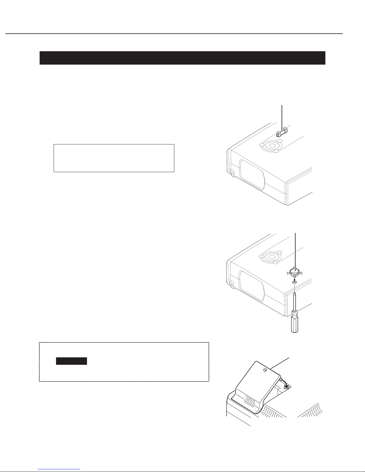
2.1 Fuse
A fuse is located inside of the projector. When the
POWER indicator is not lightning, the fuse may be
opened. Check the fuse as following steps.
The fuse should be used with the following type;
[Fuse replacing steps]
1. Remove the cabinet top and cabinet front following
to “Mechanical Disassemblies”.
2. Replace the new one with the specified type.
2.2 Thermal Switch
There is the thermal switch (SW902) inside of the
projector to detect the internal temperature rising
abnormally. When the internal temperature reaches
near 90˚C, it cuts off the AC main power supply.
The thermal switch cannot be reset itself
automatically even if the internal temperature
becomes normal. Reset the thermal switch following
to the below procedure.
[How to reset the thermal switch]
1. Insert the sharp tool like a screwdriver into a hole
on the cabinet bottom.
2. Press the reset button on the thermal switch 11
with the screwdriver.
2.3 Lamp Cover Switch
The lamp cover switch (SW901) cuts off the drive
signal to the lamp circuit when the lamp cover is
removed or not closed completely. After opening the
lamp cover for replacing the lamp ass’y, place the lamp
cover correctly otherwise the projector can not turn on.
Fuse Part No. DY4-5918-000
TYPE T6.3AH 250V FUSE
LITTLE FUSE INC. TYPE 21506.3
Before press the reset button,
make sure that the AC cord
must be disconnected from the
AC outlet.
CAUTION
Fig. 2-1
Fig. 2-2
Fig. 2-3
Fuse
Thermal switch (SW902)
Lamp cover switch
2.4 Warning Temperature and Power Failure Protection
The projector will be automatically turned off when the internal temperature of the
projector is abnormally high, or the cooling fans stop spinning, or the power supplies in
the projector are failed.
• If the WARNING indicator is flashing, it may detect the abnormal temperature inside
the projector. Check the following possible causes and wait until the WARNING
indicator stops flashing, and then try to turn on the projector.
• If the WARNING indicator lights red, it may defect the cooling fans or power supply
circuits. Check fans operation and power supply lines referring to the chapter “Power
supply & protection circuit” in the Chassis Block Diagram section.
[Possible causes]
• Air filters are clogged with dust particles. Remove dust from the air filters by following
instructions in the “Air filter care and cleaning” below.
• Ventilation slots of the projector are blocked. In such an event, reposition the
projector so that ventilation slots are not obstructed.
• Check if projector is used at higher temperature place (Normal operating temperature
is 5 to 35˚C or 41 to 95˚F)
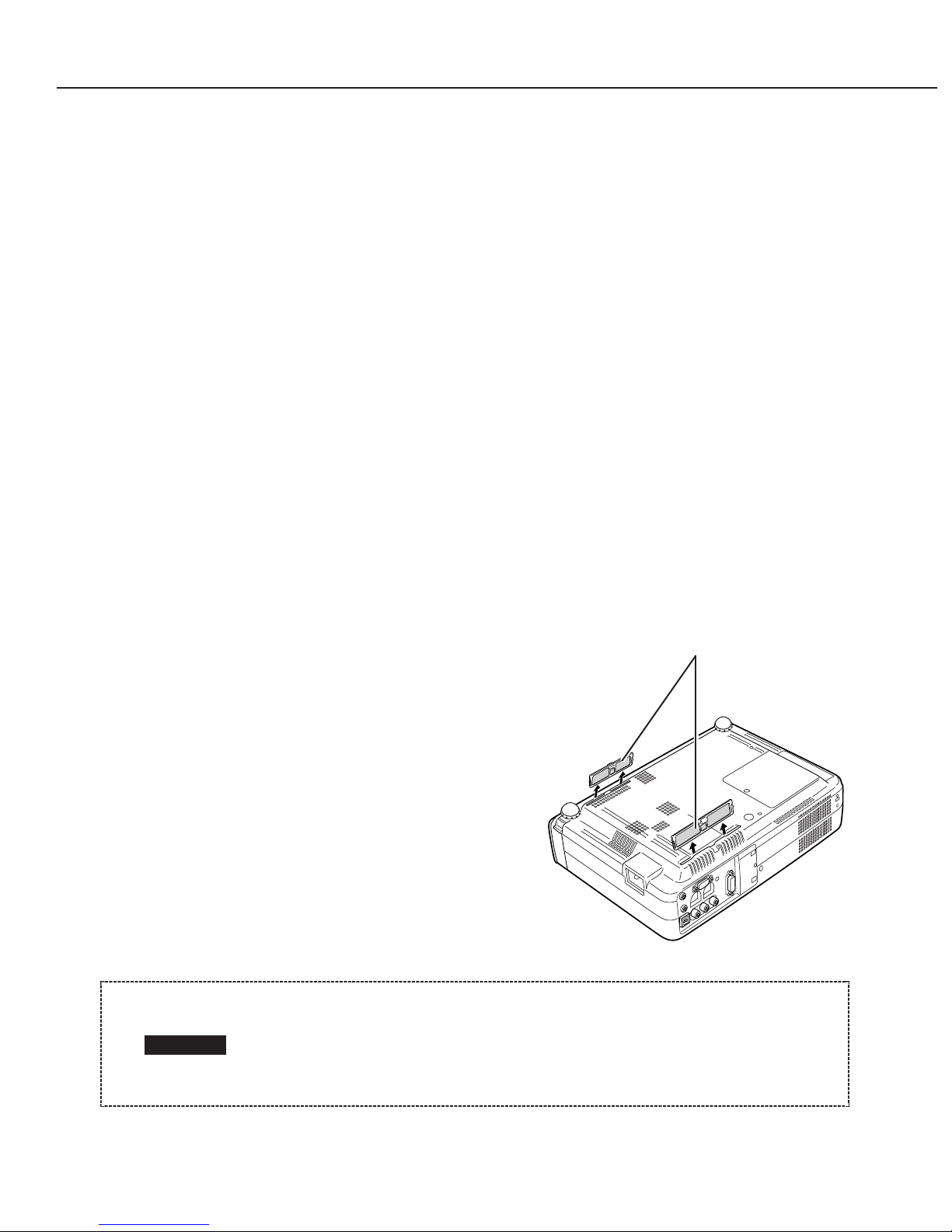
2.5 Air Filter Care and Cleaning
The removable air filter prevents dust from accumulation on the surface of the
projection lens and projection mirror. Should the air filter become clogged with dust
particles, it will reduce the cooling fan’s effectiveness and may result in internal heat
build up and reduce the life of the projector.
To clean up the air filters, follow the cleaning
procedure below:
1. Turn the power off, and disconnect the AC
power cord from the AC outlet.
2. Turn the projector up side down and remove
air filters by pulling the latches of it upward.
3. Clean the air filters with brush or wash out
the dust and particles.
4. Replace the air filters properly. Make sure
that the air filters are fully inserted.
Part 2: Repair Information
2-3
Do not operate the projector with the air filters removed. Dust may
accumulate on the LCD panel and the projection mirror degrading picture
quality.
Do not put small parts into the air intake vents. It may result in
malfunction of the projector.
CAUTION
Fig. 2-4
Air filter

Part 2: Repair Information
2-4
[RECOMMENDATION]
We recommend not to use the projector in dusty, smoky places. Using it in dusty place
may cause the poor picture quality.
When using under the dusty or smoky conditions, dust may accumulate on the LCD
panel and lens inside it, and may resultantly be projected on the screen together with
the picture.
When the above symptoms are noticed, please clean up the LCD panel and lens
following to the “Cleaning Method”.
 Loading...