

Canon LV-X2U/D78-5352, LV-S2U/D78-5362, LV-S2E/D78-5363, LV-X2J D78-5351, LV-S2J D78-5361 Service Manual
...
English Edition
PREFACE
0
General
1
SERVICE MANUAL
By Portable Document Format
LV-X2U/D78-5352
LV-X2E/D78-5353
LV-S2U/D78-5362
LV-S2E/D78-5363
Repair
2
Adjustment
3
Parts Catalog
4
Electrical Diagrams
5
DY8-1785-351 500

CANON Power Projector
LV-X2J D78-5351
LV-S2J D78-5361
CANON Multimedia Projector
LV-X2U D78-5352
LV-S2U D78-5362
LV-X2E D78-5353
LV-S2E D78-5363
SERVICE
SMANUAL

Technical Documents
Application
This CD-ROM is issued by Canon Inc. for qualified persons to learn technical theory and product
repair. This CD-ROM covers all localities where the products are sold. For this reason, there
may be information in this CD-ROM that does not apply to the product sold in your locality.
The following paragraph does not apply to any countries where such provisions are
inconsistent with local law.
Trademarks
The product names and company names described in this CD-ROM are the registered
trademarks of the individual companies.
Copyright
Canon Inc. retains the copyright to all data contained on this CD-ROM.
Reproduction, publication (including on the World Wide Web) alteration, translation into another
language, or other use of the data in whole or part, contained on this CD-ROM without the
written consent of Canon Inc., is prohibited.
PDF Files
This CD-ROM contains PDF files created using Adobe®Acrobat 4.0J. PDF files can be viewed
using Adobe®Acrobat Reader 4.0 or later.
Copyright © 2002 by Canon Inc.
CANON INC.
30-2 Shimomaruko 3-Chome, Ohta-ku,
Tokyo 146-8501, Japan
First published December, 2002

PREFACE
1. Service Manual Composition
This manual contains information on servicing the product. It has the following sections.
Part 1 General Information
Provides the basic information needed to understand the product.
Operating instructions are not included. Refer to the product's instruction book if
necessary.
Part 2 Repair Information
Provides information for disassembly, reassembly, and adjustment of the product, about
the tools required, and their application.
Part 3 Adjustment
Provides information for disassembly, reassembly, and adjustment of the product to
assure precision of the products, about the tools required, and their application.
Part 4 Parts Catalog
Part 5 Electrical Diagrams
2. Model Differences
In this series of products, there are models suffixed "J", "U", and "E". The only
differences between the models are cosmetic, mainly the designation and rating plates.
Internally, they are identical.
The accessories bundled with the product may differ from country to country.
I
Main Marketing Area Japan North America Europe
POWER PROJECTOR
MULTIMEDIA PROJECTOR MULTIMEDIA PROJECTOR
Model Name LV-X2J LV-X2U LV-X2E
LV-S2J LV-S2U LV-S2E
3. Tools & Test Equipment
The following tools and equipment are required to perform disassembly, reassembly and
adjustment.
1) Special Tools
None
2) General Purpose Tools (Commercially available, but can be purchased with the
following numbers.)
3) Test Equipment
4) Other Equipment
5) Chart/Software
II
Description Tool No. Specification Remarks
Ball Driver CY9-5002-000 2.0mm Optical Parts Removal
& Adjustment
Hex Key Set CY9-5007-000 2.0mm Optical Parts Removal
& Adjustment
Driver, adjustment CY9-5003-000 1.8mm Electrical Adjustments
Driver, Slot CY9-5004-000 4.0mm Optical Parts
Adjustment
Driver, Cross-point CY9-5005-000 No. 2 Assembly &
Disassembly
Description Tool No. Specification Remarks
Digital Multi-meter Commercially available DC1mmV~500V Electrical Adjustment
Video Signal Generator Commercially available Color Bars and Electrical Adjustment
Gray Scale
Computer Signal Commercially available Gray Scale Electrical Adjustment
Generator (or personal computer)
Oscilloscope Commercially available 100MHz response or Waveform checks and
over Electrical Adjustment
Description Tool No. Specification Remarks
Screen Commercially available Over 40" All Adjustment
Personal Computer Commercially available Windows 95 OS All Adjustment
(with a floppy disk)
Description Tool No. Specification Remarks
Monitor Tester Supplied with manual Bitmap Data All Adjustment
Gray Scale Chart Supplied with manual (XGA and SVGA) All Adjustment
Color Shading Supplied with manual Ver. 3.01 Color Shading
Correction Tool Adjustment

CONTENTS
Page
Part 1: General Information
1. FEATURES ...................................................................................................... 1-1
1.1 Development objectives ........................................................................... 1-1
1.2 Product Overview .................................................................................... 1-1
1.3 Major Features ......................................................................................... 1-2
2. SPECIFICATIONS ........................................................................................... 1-3
2.1 Type ......................................................................................................... 1-3
2.2 LCD panel ................................................................................................ 1-3
2.3 Optical box ............................................................................................... 1-3
2.4 Mechanism .............................................................................................. 1-3
2.5 Video/audio .............................................................................................. 1-3
2.6 Connectors .............................................................................................. 1-4
2.7 Standard .................................................................................................. 1-4
2.8 Accessories ............................................................................................. 1-4
2.9 Replacement Parts .................................................................................. 1-4
2.10 Options .................................................................................................. 1-5
3. NOMENCLATURE ........................................................................................... 1-6
3.1 Nomenchtor ............................................................................................. 1-6
3.2 Top controls ............................................................................................. 1-6
3.3 Rear panel terminals ................................................................................ 1-6
3.4 Computer Input terminal / Control port connector .................................... 1-6
3.5 Remote control ........................................................................................ 1-6
3.6 Remote control operating range .............................................................. 1-6
4. COMMENTARY ............................................................................................... 1-7
4.1 Optical System ......................................................................................... 1-7
4.2 Functions ................................................................................................. 1-7
4.3 Design ...................................................................................................... 1-8
5. CONNECTION DIAGRAM ............................................................................... 1-9
5.1 Connection to the computer ..................................................................... 1-9
5.2 Connecting to the video equipment ......................................................... 1-9
6. SETTING-UP THE PROJECTOR .................................................................... 1-10
6.1 Positioning the projector .......................................................................... 1-10
6.2 Installation precautions ............................................................................ 1-10
7. SUPPORTED COMPUTER SYSTEM MODE ................................................. 1-11
Part 2: Repair Information
1. SAFETY INSTRUCTIONS ............................................................................... 2-1
2. LAMP REPLACEMENT ................................................................................... 2-2
3. CIRCUIT PROTECTIONS ............................................................................... 2-4
3.1 Fuse ......................................................................................................... 2-4
3.2 Temperature Protection equipment ......................................................... 2-4
4. MECHANICAL DISASSEMBLIES .................................................................... 2-6
4.1 Cabinet - Top Removal ............................................................................ 2-6
4.2 Cabinet - Front Removal ......................................................................... 2-6
III

4.3 Main Board and Sub-Board Removal ...................................................... 2-7
4.4 Power Supply Unit and Fan (FN903) Removal ........................................ 2-7
4.5 AV Unit and Fan (FN907) Removal ......................................................... 2-8
4.6 Lamp Ballast Unit Removal ..................................................................... 2-8
4.7 Optical Unit, Fan (FN901) and Fan Louver Removal .............................. 2-9
4.8 Air Duct and Fan Removal ....................................................................... 2-9
4.9 Lens and Panel Prism Assembly Removal .............................................. 2-10
5. CLEANING ....................................................................................................... 2-11
Part 3: Adjustment
1. PRECAUTIONS FOR ADJUSTMENT ............................................................. 3-1
1.1 Service Mode ........................................................................................... 3-1
1.2 Adjustments Required after Parts Assembly and Replacement .............. 3-1
1.3 Service Mode Adjustment Items .............................................................. 3-2
1.4 IC Adjustment Data .................................................................................. 3-3
2. ELECTRICAL ADJUSTMENTS ....................................................................... 3-9
2.1 Fan Voltage Adjustment .......................................................................... 3-9
2.2 PSIG Adjustments ................................................................................... 3-9
2.3 Signal Center DC Voltage Adjustment ..................................................... 3-10
2.4 Contrast Adjustment ................................................................................ 3-11
2.5 Gain (Signal Amplitude) Adjustment ........................................................ 3-12
2.6 Flicker Adjustment ................................................................................... 3-13
2.7 White Balance Adjustment ....................................................................... 3-13
2.8 Contrast Linearity Adjustment .................................................................. 3-13
2.9 Color Shading Correction ........................................................................ 3-14
3. TEST POINTS LOCATIONS ............................................................................ 3-15
4. OPTION RESISTORS ..................................................................................... 3-16
5. CIRCUIT BLOCK DIAGRAM ............................................................................ 3-17
6. POWER SUPPLY LINES.................................................................................. 3-18
7. POWER SOURCE LIST OF IC......................................................................... 3-19
8. TROUBLESHOOTING ..................................................................................... 3-21
Part 4: Parts Catalog
Part 5: Electrical Diagrams
1. PARTS DESCRIPTION AND READING IN SCHEMATIC DIAGRAM ............. 5-1
2. DIODE, TRANSISTOR AND IC PINS .............................................................. 5-3
Schematic Diagrams ........................................................................................ A1
Printed Wiring Board Diagrams ........................................................................ B1
Schematic Diagrams (0.7SVGA 2nd) ............................................................... C1
IV

Part 1
General
Information
Part 1: General Information
1-1
1. FEATURES
1.1 Development objectives
This projector has been developed as a successor to the Multimedia Projectors "LV-
X1/LV-S1" featuring a 0.7-inch XGA panel, which were put on the market last fall.
It has the Canon's latest technologies and various new features to expand Canon's
XGA ultra-portable LCD projector product offerings in the market.
The LV-X2/LV-S2 incorporates Canon's latest technologies, such as new wide lens,
original 3P clear prisms and the latest LCD panel, to cover a wide range of fields, such
as offices and education.
1.2 Product Overview
These products are micro-portable models of Canon LV series LCD projectors.
The high-resolution model with a 0.7-inch LCD panel is equipped with a ×1.4 wide
zoom lens, which has the best magnification in the industry for the current models. The
projection distance range has been expanded so that the projector can be installed
closer to the screen.
In addition, the newly developed LCD panel improves efficiency of using light, and the
Canon's original optical box with a 3P prism provides the same level of brightness as the
previous model at a lower cost.
Users can select one of two models: a high-end model with an LCD panel with a
microlens and an inexpensive model with an LCD panel with no microlens.
LV-X2 External View (LV-S2 is identical to the LV-X2 except the logo)

1.3 Major Features
●Newly-developed 1.4× wide zoom lens
The wide projection lens is equipped with a ×1.4 power-driven zoom that is the
highest magnification in the industry by using the Canon's latest optical design
technology. The 100" screen size is supported in the range 2.8 to 4.0m.
● Canon's original optical box
In addition to the newly developed wide zoom lens, Canon's original technologies,
such as 3P clear prism and free curvature mirror, have been adopted.
The cost has been reduced by using original techniques, and the efficiency of using
light has been improved drastically with a new LCD panel.
● Provision of reproducibility suited to display contents with a newly designed image
processing LSI
The following two functions can be turned on or off to project the optimum images.
• Monochrome expansion: Images with low contrast are displayed clearly by
emphasizing gradations.
• Flesh color correction: Dull skin color can be corrected by changing gradations.
● XGA real projection, SXGA high-quality compression display (LV-X2)
A 0.7" LCD panel with 1024 × 768 pixels is used to achieve XGA real projection and
SXGA high-quality digital compression display.
* The LV-S2 has an LCD panel with 800 × 600 pixels for SVGA real projection and
XGA compression display.
● XGA model with 1100 ANSI lumen and SVGA model with 1000 ANSI lumen
A newly developed LCD panel with a high aperture ratio is used with a F1.6 lens to
provide the same level of brightness as the conventional model.
Part 1: General Information
1-2

Part 1: General Information
1-3
2. SPECIFICATIONS (Model-specific items are underlined.)
2.1 Type Micro-portable LCD Projector
2.2 LCD panel
1. Type: Polysilicon active matrix TFT
LV-X2: with microlens; LV-S2: with no microlens
2. Size/number: 0.7 model (4:3 aspect ratio) × 3
3. Number of pixels: LV-X2: 1024 × 768 pixels (XGA);
LV-S2: 800 × 600 (SVGA)
4. Contrast ratio: LV-X2: 300:1; LV-X2: 350:1
(all white: all black)
2.3 Optical box
1. Type: Dichroic mirror separation/prism synthesis system
2. Light source: LV-X2: 132W UHP lamp; LV-S2: 150W UHP lamp
3. Projection lens configuration: 10 groups, 10 lenses
4. F value/focal length: F1.6 to 1.9, f20.3 to 28.2mm
5. Zoom magnification: ×1.4
6. Zoom/focus: Manual
2.4 Mechanism
1. Lens shift: 19:1 fixed
2. Elevation mechanism: Up by 10.7 degrees
2.5 Video/audio
1. Brightness/periphera: LV-X2: 1100 ANSI lumen, illuminance ratio 85%;
illuminance ratiol LV-S2: 1000 ANSI lumen, illuminance ratio 85%
2. Correct projection distance: 1.1 to 8.0 m
3. Size of projection image: 29" to 200"
4. Resolution of display supported: LV-X2: SXGA (compression)/XGA/SVGA/VGA
LV-S2: XGA (compression)/SVGA/VGA
5. Digital zoom magnification: LV-X2: ×56% to ×16;
LV-S2: ×66% to ×16
6. Keystone correction range: Vertical and horizontal: ±20 degrees
7. Horizontal resolution (Video input): LV-X2: 550 TV lines; LV-S2: 500 TV lines
8. Scanning frequency: 15KHz to 100KHz for horizontal sync. 50Hz to
100Hz for vertical sync. Up to 140MHz for dot clock
9. Color system: NTSC/PAL/SECAM/NTSC4.43/PAL-M/PAL-N
10. Built-in speaker: 2cm × 3.5cm, 1W monaural

2.6 Connectors
1. Analog RGB input: Mini D-sub 15-pin
2. Video input: RCA × 3: (Use three RCA terminals for component
input and Y terminal for composite input.)
Mini DIN 4-pin: S-Video
3. Audio input: Stereo mini jacks × 2 (computer input, video input)
4. Audio output: Stereo mini jack
5. Mouse control: Mini DIN 8 pins, USB type (type B)
2.7 Standard
1. Dimensions (W × D × H): 260mm × 244.5mm × 76mm
(Not total length)
2. Net Weight: 2.9 kg
3. Rated supply voltage: Japan: 100V / United States:100-120V /
Europe: 200-240V, 50/60Hz
4. Power consumption: LV-X2: 210W; LV-S2: 250W
5. Noise: 38 dB
6. Operating/Storage temperature: 5 to 35˚C/–10 to 60˚C
2.8 Accessories
1. Remote control
Thin card type remote control. The image can be wirelessly controlled.
A lithium battery is included.
2. Computer connection cable (Dsub 15-Dsub 15)
Used to input an analog RGB video signal from a PC.
3. Lens cap
Used to protect the lenses against dirt and dust when they are not used or are being
transported.
4. Soft carrying case
Used to prevent contamination when the projector is being transported or not in use.
5. Power cord
Connect the power cable into the socket in the main unit and supply voltage from an
outlet.
(A power cord for Japan, United States or Europe is supplied.)
2.9 Replacement Parts
1. Canon replacement lamp (LV-LP15) (LV-X2)
Recommended lamp replacement time: 1000 hours
* Time when residual rate of 50% and illuminance maintenance rate of 50% are
maintained
2. Canon replacement lamp (LV-LP14) (LV-S2)
Recommended lamp replacement time: 1000 hours
* Time when residual rate of 50% and illuminance maintenance rate of 50% are
maintained
Part 1: General Information
1-4

2.10 Options
1. Remote control with mouse laser LV-RC01
2. Mouse control cable LV-CA25 (PS/2), LV-CA26 (serial), LV-CA27 (ADB)
3. Canon ceiling mount fitting LV-CL06
Hanger for ceiling mount
Part 1: General Information
1-5

3. NOMENCLATURE
3.1 Nomenchtor: See the attached sheet
(Owner's Manual, page 7).
3.2 Top controls: See the attached sheet
(Owner's Manual, page 16).
3.3 Rear panel terminals: See the attached sheet
(Owner's Manual, page 11).
3.4 Computer Input terminal / Control port connector:
See the attached sheet
(Owner's Manual, page 43).
3.5 Remote control: See the attached sheet
(Owner's Manual, page 14).
3.6 Remote control operating range: See the attached sheet
(Owner's Manual, page 15).
Part 1: General Information
1-6

Part 1: General Information
1-7
4. COMMENTARY
4.1 Optical System
High brightness and high contrast are implemented at a low cost by a newly designed
×1.4 wide zoom lens and an improved LCD panel, combined with the Canon's unique 3P
prisms.
● ×1.4 wide zoom lens
A wide zoom lens with a short focal length of 20.3 mm and high magnification of ×1.4
is designed as a bright large-aperture projection lens (F1.6).
The optical system has 10 groups of 10 lenses, including 5 groups of zoom lenses.
The number of lenses has been reduced and the zoom lenses have been designed
optimally using a replica aspherical lens for G1 and double-sided aspherical lens for
G9 to suppress distortion aberrations due to widened angles.
All lenses are made from lead-free glass.
● LCD panel
The new type of LCD panel has a higher open area ratio than conventional ones by
improving production technologies to increase efficiency of using light.
* Since the wide projection lenses are used, the F value increases, but the light
intensity is the level of the previous model.
● 3P prism
Like the clear prisms for X1/S1, the 3P prism produces images with uniform color on
the screen.
The cost has been cut down by reducing the number of parts.
● Projection screen size
A29 to 200" screen display at the proper projection distance of 1.1 to 8.0 m
(See 6.1 Relationship between screen distance and screen size.)
4.2 Functions
● Zoom/focus
The Wide/Tele zoom ratio is 1.4, and the projection size can be changed by manual
zooming within the range.
The focus can be adjusted to the correct point manually.
● Monochrome expansion
It is effective when projecting dark images at night scenes or blurred images with a
low contrast.
When this function is turned on, the video signal output is controlled automatically to
maximize the black and white levels of output images.

Part 1: General Information
1-8
● Flesh color correction
The image is processed so that the color of the skin of persons on the screen is real.
When this function is turned on, gradations are changed to the flesh color is set to the
preset value.
Since gradations are changed, the background color may become different.
4.3 Design
The high-quality and all-round "Stylish Form" fits various office environments and
presentation scenes.
The wide zoom lens with a short focal length makes it possible to install the projector
in various places, from bright offices and home theaters for watching movies.
● Styling
The comfortable and elastic three-dimensional form is combined with a design like a
video equipment to produce a shape that makes the user proud of owning it and give
an impression of precision and high quality.
The impressive and stylish design, measures to assure high intensity and high image
quality, and the compact layout are balanced at a high level.
● Details
The operation panel is designed to be round with a curved relief and have Caribbean
water blue color. The "circle" symbolizes "harmony, link, bond and communication",
and "water" symbolizes "light, life, purity and transparency". It evokes a sophisticated
image, high quality and is user-friendly so that it can be used in various places.
The operation panel on top of the projector is inclined backward to improve
operability. Operation keys are laid out around the cursor keys so that they can be
operated by touching without looking at them.
The exhaust port that exhausts heat and causes noise has been laid out at the front
panel far away from audience, and is covered with a punching metal to improve the
appearance of the front panel and give an impression of sophisticated image.
● Long life design
A material with a color that is not faded easily by stain or discoloration has been
selected. It is designed to be in harmony with the atmosphere of many installation
locations, and gives a feeling of high quality so that it can be used for a long period of
time.
● Remote control
A thin card type of remote control is used like the one used with the LV-X1/S1. The
remote control is designed not only to look good, but also be user friendly, and can be
used easily.

Part 1: General Information
1-9
5. CONNECTION DIAGRAM
5.1 Connection to the computer: See the attached sheet
(Owner's Manual, page 12).
5.2 Connecting to the video equipment: See the attached sheet
(Owner's Manual, page 13).

Part 1: General Information
1-10
6. SETTING-UP THE PROJECTOR
6.1 Positioning the projector: See the attached sheet
(Owner's Manual, page 9).
6.2 Installation precautions: See the attached sheet
(Owner's Manual, page 10).

Part 1: General Information
1-11
7. SUPPORTED COMPUTER SYSTEM MODE
See the attached sheet (Owner's Manual, page 23).


Part 2
Repair
Information
Part 2: Repair Information
2-1
1. SAFETY INSTRUCTIONS
The following precautions must be observed during servicing and inspection.
Observe all safety precautions.
Comply with all caution and safety-related notes provided on the cabinet back, cabinet
bottom, inside the cabinet, on the chassis or components, as well as the precautions
shown in the instruction manual during servicing.
Avoid electric shock.
Since an AC voltage is applied to the chassis for the set, touching the chassis during
power-on may cause electric shock. When service is performed during power on, use an
insulation transformer, wear protective gloves, and remove the plug during parts
replacement. As there are high-voltage areas inside the projector, handle it with care
when the power is on.
Use specified parts.
The parts of the set have safety properties, such as inflammability and voltage
withstand. Therefore, use replacement parts with the same characteristics as the
original ones. The critical components for safety are indicated by mark in the
schematic diagram and parts list must be replaced by the recommended parts.
Reinstall parts and wires in their original positions.
Insulating materials, such as tubes and tape, are used and some components are
installed over a PC board for safety. Reinstall internal wires with clamps so that they do
not touch any heat-generating or high-voltage parts.
Safety check after service
Verify that service locations are not deteriorated and all removed screws, parts and
wires are installed in their original positions. In addition, perform the following test to
ensure safety.
Insulation resistance test method
Remove the plug from the electric outlet and press the power switch. Using a 500V
insulation resistance tester (or a multimeter if any insulation resistance tester is not
available), check that the insulation resistance between each terminal of the plug and
external exposed connector (external speaker connector, remote control connector, AV
input/output connector, etc.) is 1M ohm or higher. If not, the set must be inspected
and repaired.
Components indicated by mark designate components in which safety can be of special significance.
It is, therefore, particularly recommended that the replacement of these parts be made by exactly the
same parts. Using unspecified parts may worsen failure or cause fire or electric shock.
Eye damage may result from directly viewing the light produced by the lamp used in this equipment.
Always turn off the lamp before opening the cover.
Never turn the power on without the lamp to avoid electric shock or damage of the devices since the
stabilizer generates high voltages (15kV - 25kV) at its starts.
Since the lamp is very high temperature during units operation replacement of the lamp should be done
at least 45 minutes after the power has been turned off, to allow the lamp cool-off.
Precautions for servicing
Part 2: Repair Information
2-2
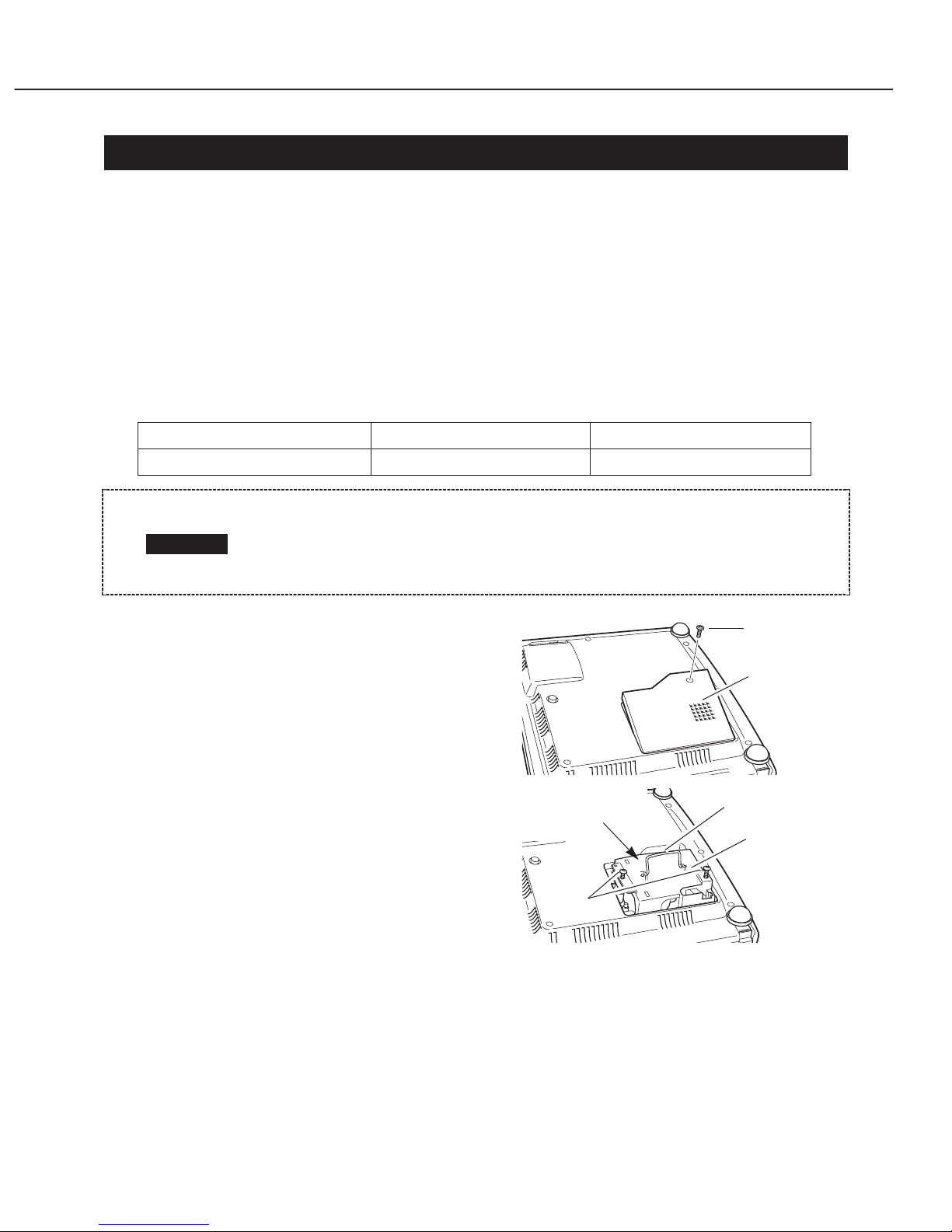
2. LAMP REPLACEMENT
LAMP REPLACE indicator illumination
When the lamp is approaching the end of its life cycle, the LAMP REPLACE indicator
(yellow) lights. If the image is dark or color is unnatural, the lamp should be replaced.
The LAMP REPLACE indicator lights whenever the projector is turned ON until the lamp
is replaced.
Lamp replacement procedure
Replace the entire lamp assembly when replacing the lamp. Be sure to install a lamp
assembly of the same type. Contact your dealer to purchase a lamp assembly. The
following information is necessary when ordering it.
1. Turn off the projector and disconnect the
AC cord. Let the projector cool for at least
45 minutes.
2. Remove a screw with a Phillips
screwdriver and remove the lamp cover.
3. Loosen 2 screws on the lamp assembly
and pull it out by grasping the handle.
4. Install the new lamp assembly securely
and tighten the 2 screws.
5. Reinstall the lamp cover and tighten the
2 screws.
The lamp becomes very hot when the projector is in operation. Allow the
projector to cool for at least 45 minutes before replacing the lamp. Burns
can occur from touching the light bulb immediately after the projector
stops.
CAUTION
Lamp cover
Screw
Screw
Handle
Do not touch the glass
surface to prevent
contamination.
Lamp Assembly
Fig. 2-1
Replacement Lamp Parts No. LV-LP15 (DY5-0202-000)
Projector Model No. LV-X2 (PHILIPS)
LV-LP14 (DY5-0211-000)
LV-S2 (OSRAM)

Reset the lamp replacement monitor timer.
When the Lamp Replace Counter is reset, the LAMP REPLACE Indicator (yellow) stops
lighting. How to reset the lamp replacement monitor timer.
1. Turn the projector on. Press the MENU button to display the ON-SCREEN MENU.
Press the POINT LEFT/RIGHT buttons to position the pointer at the setting menu
icon.
2. Press the POINT DOWN button to move the pointer down to the "Lamp Counter
Reset" icon, then press the SET button.
3. The message "Lamp Counter Reset?" is displayed. Press the POINT UP/DOWN
buttons to position the pointer at and press the SET button to select it. The
counter will be reset.
* Do not reset the Lamp Replacement Monitor Timer, except after the lamp is
replaced.
How to check the lamp replacement monitor timer
The LAMP REPLACEMENT indicator will illuminate
when the lamp counter reaches 1000 hours. This is to
indicate that lamp replacement is required.
You can check the accumulated illumination time of
the lamp as follows:
1. Press and hold the pointer ( ^) on the projector for more than 20 seconds to enter
the service mode.
2. The lamp replacement counter service menu is displayed as shown in the photograph
on the right.
The menu will disappear automatically in approx. five seconds.
Yes
Part 2: Repair Information
2-3
Part 2: Repair Information
2-4
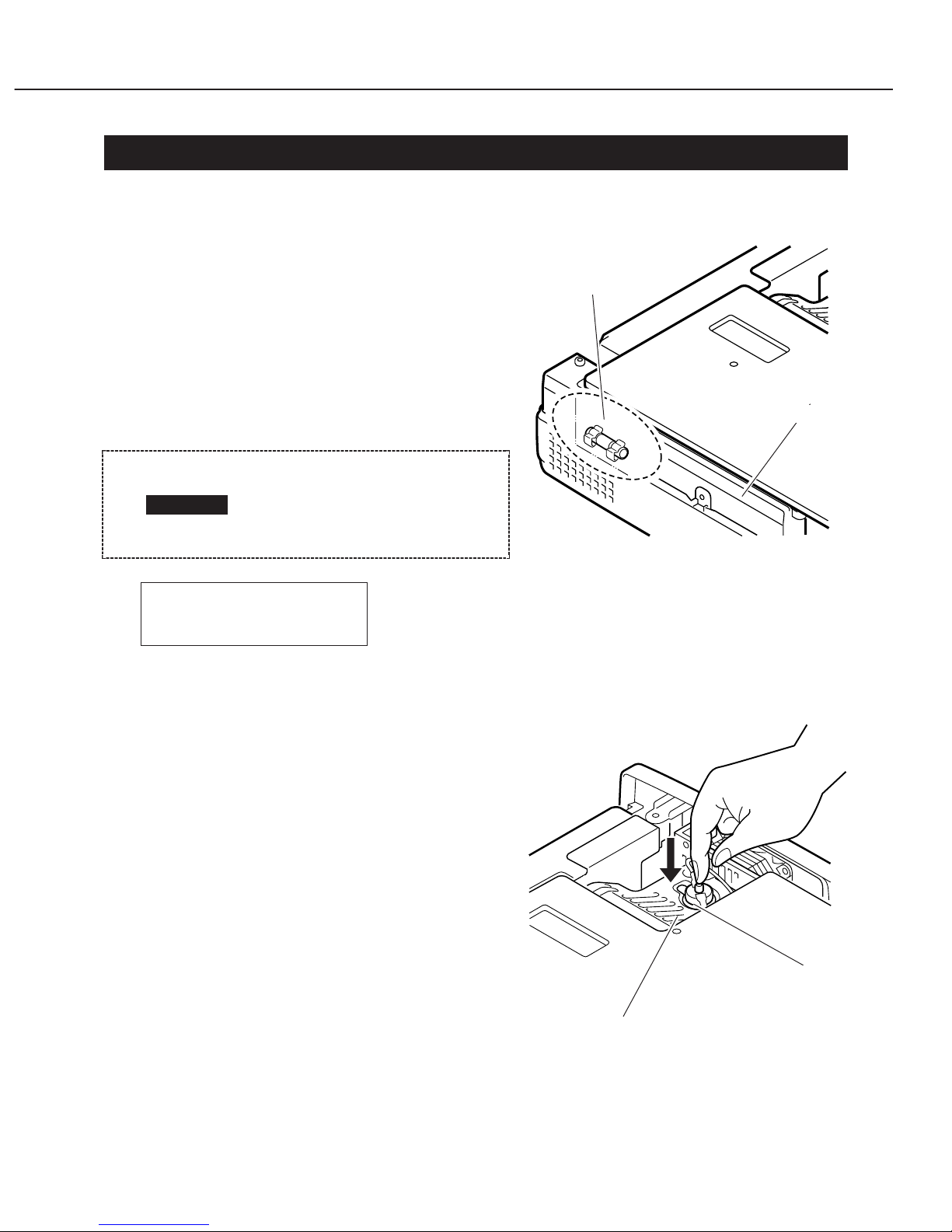
3. CIRCUIT PROTECTIONS
This projector is equipped with the following circuit protections.
3.1 Fuse
A fuse is attached to the power supply.
When the LAMP indicator or the READY
indicator is illuminated, the fuse is normal.
Check the fuse as follows:
1. Remove the power supply unit according
to the servicing procedure.
2. Remove the fuse and check it with a
multimeter.
3.2 Temperature Protection equipment
To protect circuitry and optical components from abnormal rise of the internal
temperature, the following temperature
protections are provided:
1) Thermal Sensor Circuit
If the internal temperature of the projector
rises excessively, the WARNING TEMP.
indicator flashes and the cooling fan starts to
run to cool the projector. When the
temperature becomes normal, the indicator
stops flashing. If it does not stop, unplug the
AC cord from the outlet and check and clean
the air filter. If the indicator still flashes,
inspect the inside (cooling fan, etc.) of the
projector.
Fuse 250V 6.3AAA
Part No. DY4-5918-000
The specified fuse should
be used. Using an
unspecified fuse may cause
fire or electric shock.
CAUTION
Fig. 2-2
Fig. 2-3
Fuse
Power supply unit
Reset button
Thermal switch
(SW902)

2) Thermal Switch (SW902)
When the internal temperature of the lamp or projector rises abnormally, the thermal
switch (SW902) located in the projector turns off the power supply automatically. Reset
the thermal switch manually. To reset it, unplug the AC cord from the outlet, open the
top cabinet, and press the reset button.
Part 2: Repair Information
2-5
Let the projector cool sufficiently before resetting the thermal switch.
Pressing the reset button while the projector is hot may cause burns.
CAUTION

4. MECHANICAL DISASSEMBLIES
4.1 Cabinet - Top Removal
1. Remove five screws A and B.
2. Grasp the rear both ends of
Cabinet-front with both hands,
and slightly pull upward.
3. Release hook, by pressing down
"C" portion lightly with finger.
4. Grasp the rear both ends of
Cabinet-front with both hands,
pull up and remove upwards.
4.2 Cabinet - Front Removal
1. Remove four screws A and B.
Screws-A and screws-B are used
different kind screws. Check the
kind of screw, and proper screw
should be used.
2. Turn the focus-ring of Projection
lens fully clockwise.
3. Set zoom-lever of Projection lens
to under lens.
4. Slightly pull the upper part of
Cabinet-front forward with both
hands. (hook is released and
cabinet front is removed.)
5. Remove a screw and, next,
remove Unit R/C.
Part 2: Repair Information
2-6
Fig. 2-5
Fig. 2-4
Be careful not to damage Hook. Cabinet-top is being fixed with cabinetfront by hook.
CAUTION
Be careful not to damage Hook. There is hook which is fixing Cabinetfront and Cabinet-bottom under Projection lens.
CAUTION
A
A
B
B
B
C
Hook
Front cabinet
Top cabinet
A
A
B
B
Front cabinet
Bottom cabinet
Hook
R/C unit
 Loading...