

Canon LV-7545U, D78-5232, LV-7545E, D78-5233 Service Manual
SERVICE MANUAL
English Edition
LV-7545U/D78-5232
LV-7545E/D78-5233
By Portable Document Format
1 General
0 PREFACE
2 Repair
3 Adjustment
4 Troubleshooting
5 Parts Catalog
6 Electrical Diagrams
To Contents
DY8-1785-231 500

CANON Power Projector
LV-7545E D78-5231
SERVICE
SMANUAL

Technical Documents
Application
This CD-ROM is issued by Canon Inc. for qualified persons to learn technical theory and product
repair. This CD-ROM covers all localities where the products are sold. For this reason, there
may be information in this CD-ROM that does not apply to the product sold in your locality.
The following paragraph does not apply to any countries where such provisions are
inconsistent with local law.
Trademarks
The product names and company names described in this CD-ROM are the registered
trademarks of the individual companies.
Copyright
Canon Inc. retains the copyright to all data contained on this CD-ROM. Reproduction,
publication (including on the World Wide Web) alteration, translation into another language, or
other use of the data in whole or part, contained on this CD-ROM without the written consent of
Canon Inc., is prohibited.
PDF Files
This CD-ROM contains PDF files created using Adobe®Acroba 4.0J. PDF files can be viewed
using Adobe®Acrobat Reader 4.0 or later.
Copyright © 2001 by Canon Inc.
CANON INC.
30-2 Shimomaruko 3-Chome, Ohta-ku,
Tokyo 146-8501, Japan
First published Novemver, 2001

PREFACE
1. Service Manual Composition
This manual contains information on servicing the product. It has the following
sections.
Part 1 General Information
Provides the basic information needed to understand the product.
(Operating instructions are not included. Refer to the product's instruction book if
necessary.)
Part 2 Repair Information
Provides information for disassembly, reassembly, and adjustment of the product, about
the tools required, and their application.
Part 3 Adjustment
Provides information for disassembly, reassembly, and adjustment of the product to
assure precision of the products, about the tools required, and their application.
Part 4 Troubleshooting
Part 5 Parts Catalog
Part 6 Electrical Diagrams
2. Model Differences
In this series of products, there are models suffixed "J", "U", and "E". The only
differences between the models are cosmetic, mainly the designation and rating plates.
Internally, they are identical.
The accessories bundled with the product may differ from country to country.
I
Main Marketing Area
Japan North America Europe
Model Name
POWER PROJECTOR
MULTIMEDIA PROJECTOR MULTIMEDIA PROJECTOR
LV-7545J LV-7545U LV-7545E

3. Tools & Test Equipment
The following tools and equipment are required to perform disassembly, reassembly
and adjustment.
1) Special Tools
None
2) General Purpose Tools (Commercially available, but can be purchased with
the following numbers.)
3) Test Equipment
4) Other Equipment
5) Chart/Software
II
Description Tool No. Specification Remarks
Ball Driver CY9-5002-000 2.0mm Optical Parts Removal
& Adjustment
Hex Key Set CY9-5007-000 2.0mm Optical Parts Removal
& Adjustment
Driver, adjustment CY9-5003-000 1.8mm Electrical Adjustments
Driver, Slot CY9-5004-000 4.0mm
Optical Parts Adjustment
Driver, Cross-point CY9-5005-000 No.2 A
ssembly & Disassembly
Description Tool No. Specification Remarks
Digital Multi-meter Commercially DC1mmV~500V Electrical Adjustment
available
Video Signal Generator
Commercially Color Bars and Gray
Electrical Adjustment
available Scale
Computer Signal Commercially Gray Scale
Electrical Adjustment
Generator available (or personal computer)
Oscilloscope
Commercially 100MHz response or Waveform Checks and
available over Electrical Adjustment
Description Tool No. Specification Remarks
Screen
Commercially Over 40"
All Adjustment
available
Personal Computer
Commercially Windows 95 OS
All Adjustment
available (with a floppy disk)
Description Tool No. Specification Remarks
Monitor Tester Supplied with manual Bitmap Data All Adjustment
Gray Scale Chart Supplied with manual (XGA and SVGA) All Adjustment
Color Shading
Supplied with manual Ver.1.01
White Uniformity
Correction Tool Adjustment

CONTENTS
Page
Part 1: General Information
1. FEATURES ...................................................................................................... 1-1
1.1 Development objectives ........................................................................... 1-1
1.2 Major Features ......................................................................................... 1-2
2. LV-7545 SPECIFICATIONS ............................................................................ 1-3
2.1 Type.......................................................................................................... 1-3
2.2 LCD panel................................................................................................. 1-3
2.3 Optical box................................................................................................ 1-3
2.4 Mechanism ............................................................................................... 1-3
2.5 Video/audio............................................................................................... 1-3
2.6 Connectors ............................................................................................... 1-4
2.7 Standard ................................................................................................... 1-4
2.8 Accessories .............................................................................................. 1-4
2.9 Options ..................................................................................................... 1-4
2.10 Others ..................................................................................................... 1-4
3. NOMENCLATURE ........................................................................................... 1-5
3.1 Name of each part of projector ................................................................. 1-5
3.2 Top controls and indicators....................................................................... 1-5
3.3 Rear panel terminals ................................................................................ 1-5
3.4 Computer Input terminal/Control port connector ...................................... 1-5
3.5 Remote control ........................................................................................ 1-5
3.6 Remote control operating range .............................................................. 1-5
4. COMMENTARY ............................................................................................... 1-6
4.1 External appearance design .................................................................... 1-6
4.2 Optical System ......................................................................................... 1-6
4.3 Turbo Bright System ................................................................................ 1-7
4.4 Video Input System .................................................................................. 1-7
4.5 Image Control .......................................................................................... 1-8
4.6 Mechanism .............................................................................................. 1-8
4.7 Replacement Lenses ............................................................................... 1-9
5. CONNECTION DIAGRAM ............................................................................... 1-11
5.1 Connection to the computer ..................................................................... 1-11
5.2 Connecting to the video equipment ......................................................... 1-11
6. SETTING-UP THE PROJECTOR .................................................................... 1-12
6.1 Positioning the projector .......................................................................... 1-12
6.2 Installation precautions ............................................................................ 1-12
7. SUPPORTED COMPUTER SYSTEM MODE ................................................. 1-13
Part 2: Repair Information
1. SAFETY INSTRUCTIONS ............................................................................... 2-1
2. CIRCUIT PROTECTIONS ............................................................................... 2-2
2.1 Fuse ......................................................................................................... 2-2
III

2.2 Thermal Switch ........................................................................................ 2-2
2.3 Interlock Switch ........................................................................................ 2-3
2.4 Warning Temperature and Power Failure Protection .............................. 2-3
2.5 Air Filter Care and Cleaning .................................................................... 2-4
3. SERVICE (MECHANICAL DISASSEMBLES) ................................................. 2-5
3.1 Cabinet Top Removal .............................................................................. 2-5
3.2 Front Cabinet Removal ............................................................................ 2-6
3.3 Main Board Removal ............................................................................... 2-7
3.4 AV and Rear Panel Removal ................................................................... 2-7
3.5 Lamp Ballast Unit Removal ..................................................................... 2-8
3.6 Optical Unit Removal ............................................................................... 2-8
3.7 Prism Base Removal ............................................................................... 2-9
3.8 Power Supply Unit Removal .................................................................... 2-9
3.9 Filter Unit, Thermal Switch and Interlock Switch Removal ...................... 2-10
3.10 Fan (FN901, FN902) Removal .............................................................. 2-10
4. OPTICAL PARTS DISASSEMBLES AND REASSEMBLES ........................... 2-11
4.1 Projection Lens Removal ......................................................................... 2-11
4.2 Polarized Glass (IN) Ass'y Disassembly .................................................. 2-11
4.3 Relay Lens Ass'y Disassembly ................................................................ 2-12
4.4 Polarized Glass (OUT) Ass'y Disassembly .............................................. 2-12
4.5 Bright Motor Ass'y Disassembly .............................................................. 2-13
4.6 Optical Unit Opening ................................................................................ 2-13
4.7 Condenser Lens Removal ....................................................................... 2-14
4.8 Optical Filter Removal .............................................................................. 2-14
4.9 Locations and Directions ......................................................................... 2-15
5. LCD PANEL/PRISM ASS'Y REPLACEMENT ................................................. 2-16
5.1 LCD Panel/Prism Ass'y Replacement ...................................................... 2-16
5.2 Note on LCD Panel/Prism Ass'y Mounting .............................................. 2-17
6. CLEANING ....................................................................................................... 2-18
7. LAMP REPLACEMENT ................................................................................... 2-19
Part 3: Adjustment
1. PRECAUTIONS FOR ADJUSTMENT ............................................................. 3-1
1.1 Adjustments after Parts Replacement ..................................................... 3-1
1.2 Service Adjustment Menu Operation ....................................................... 3-2
1.3 IC Adjustment Data Table ........................................................................ 3-3
2. ELECTRICAL ADJUSTMENTS ....................................................................... 3-10
2.1 Output Voltage Adjustment ...................................................................... 3-10
2.2 +16V Adjustment ..................................................................................... 3-11
2.3 Video Center Adjustment ......................................................................... 3-11
2.4 PC Pedestal Adjustment .......................................................................... 3-11
2.5 PSIG Adjustment ..................................................................................... 3-12
2.6 Black Level Adjustment ........................................................................... 3-12
2.7 PC Gain Adjustment ................................................................................ 3-13
2.8 PC Gamma Shift Adjustment ................................................................... 3-13
2.9 HTDV Pedestal Adjustment ..................................................................... 3-13
2.10 HDTV A/D Input Adjustment .................................................................. 3-14
IV

2.11 HDTV Gain Adjustment ......................................................................... 3-15
2.12 VIDEO Pedestal Adjustment .................................................................. 3-16
2.13 VIDEO A/D Input Adjustment ................................................................. 3-16
2.14 A/D Offset Adjustment ........................................................................... 3-17
2.15 Video Gain Adjustment .......................................................................... 3-17
2.16 Video Gamma Shift Adjustment ............................................................. 3-18
2.17 Common Center Adjustment ................................................................. 3-18
2.18 White Balance Adjustment ..................................................................... 3-18
2.19 Note on White Uniformity Adjustment .................................................... 3-18
3. OPTICAL ADJUSTMENTS .............................................................................. 3-19
3.1 Contrast Adjustment ................................................................................ 3-19
3.2 Condenser Lens Adjustment ................................................................... 3-20
3.3 Relay Lens (OUT) Adjustment ................................................................. 3-21
4. TEST POINTS AND LOCATIONS ................................................................... 3-22
Part 4: Troubleshooting
1. TROUBLESHOOTING ..................................................................................... 4-1
1.1 No Power ................................................................................................. 4-1
1.2 No picture ................................................................................................ 4-4
1.3 No sound ................................................................................................. 4-7
1.4 Lens Motor Error ...................................................................................... 4-8
2. PORT FUNCTIONS ......................................................................................... 4-9
2.1 System control & I/O port table (IC801) ................................................... 4-9
2.2 Parallel I/O expander (IC1801, M66500FP) ............................................. 4-11
2.3 IC bus I/O expander (IC1641, M62320FP) port function ......................... 4-12
2.4 IC bus DA converter (IC212, M62393FP) port function ........................... 4-12
2.5 IC bus DA converter (IC2381, M62393FP) port function ......................... 4-12
2.6 IC bus DA converter (IC3551, M62399FP) port function ......................... 4-13
2.7 IC bus DA converter (IC3501, M62399FP) port function ......................... 4-13
3. WAVEFORMS ................................................................................................. 4-14
4. IC BLOCK DIAGRAMS .................................................................................... 4-16
Part 5: Parts Catalog
Part 6: Electrical Diagrams
1. PARTS DESCRIPTION AND READING IN SCHEMATIC DIAGRAM.............. 6-1
2. DIODE, TRANSISTOR AND IC PINS............................................................... 6-3
Circuit Block Diagram (LV-7545U/E)................................................................. A3
Power Supply Lines (LV-7545U/E) ................................................................... A4
Schematic Diagrams ......................................................................................... A5
Printed Wiring Board Diagrams......................................................................... A13
V


Part 1
General
Information
1. FEATURES
1.1 Development objectives
This projector has been newly developed as a successor to the Canon Multimedia
Projector "LV-7535" as a "flagship model" to achieve the highest brightness in its class,
high quality and functions.
As the recent market trend shows that the brightness of the ultra-portable class (0.9")
of projectors is increasing greatly, higher functions and performance are being
demanded. Since they are used in various places, such as large conference rooms,
halls, and offices, they must have flexible functions.
The product has a Canon's unique power-driven Turbo Bright System that provides
the top-level brightness at its class and has the replacement lens system and power lens
shift mechanism that reflect the Canon's design concept to achieve both high quality
and installability. In addition, it has various interfaces to provide the features and
performance suitable as a flagship model with system scalability in mind.
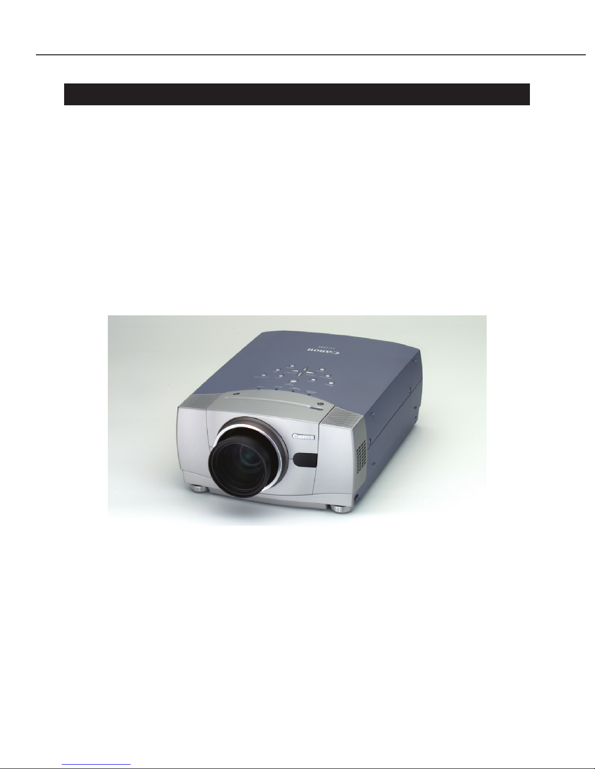
Fig. 1-1 LV-7545 External View
Part 1: General Information
1-1

1.2 Major Features
● New power-driven Turbo Bright System. Highest brightness of 3700 ANSI lumen in the
class
The projector achieves the highest brightness in its class with the Canon's original
Turbo Bright System and new optical design.
A remote control can be used to switch between Bright ON and OFF.
● XGA LCD panel with contrast ratio of 800:1
A high contrast of 800:1 is achieved by improving transmittance of the 1.3" LCD panel
with 1024 × 768 pixels and using a contrast improvement filter.
High-quality SXGA projection is provided by XGA real projection and digital
compression.
● Power-driven lens shift mechanism. Three types of optional replacement lenses
The power-driven lens shift mechanism can shift the projection screen position
vertically.
In addition to the standard lens, three types of optional replacement lenses (ultra wide
angle lens, wide angle zoom lens and long focus zoom lens) are available.
These functions can cope with various installation conditions, such as height and
distance, flexibly to provide high-quality projection all the time.
● Video mode selection function suitable for projection data
The optimum gradation can be reproduced according to projection data for PC input
and video input by switching between video modes: standard/high contrast for PC
input and standard/cinema.
● Clear PC image by DVI. High-quality video image by the progressive scan function
Supports digital interface (DVI) to reproduce clear PC images.
Uses progress scan to project higher-quality video and HDTV images.
● 37dB silent design
The fan speed is optimized by detecting the inside temperature.
The noise is suppressed by reducing the unnecessary increase in fan speed.
● Extended Digital Keystone function, up to ±40 degrees
Smoothly corrects for "keystone" effect, giving a square image with up to 40 degrees
tilt.
Part 1: General Information
1-2

2. LV-7545 SPECIFICATIONS
2.1 Type Portable XGA LCD Projector
2.2 LCD panel
1. Type Polysilicon active matrix TFT with microlens
2. Size/number 1.3 model (4:3 aspect ratio) × 3
3. Number of pixels 1024 × 768 pixels (XGA)
4. Contrast ratio 800:1 (all white:all black)
2.3 Optical box
1. Type Dichoic mirror separation/prism synthesis
2. Light source 200W UHP lamp
3. Projection lens 11 groups, 13 lenses
configuration
4. F value/focal length 1.7 to 2.0, 48.2 to 62.6mm,
5. Zoom magnification ×1.3
6. Zoom/focus Power
2.4 Mechanism
1. Lens shift 1:1 to 10:0, power
2. Elevation mechanism UP by 10.5 degrees (Maximum)
2.5 Video/audio
1. Brightness 3700/3200 ANSI lumen (Bright ON/Bright OFF),
illuminance ratio 90%
2. Correct projection distance 1.4 to 14.7 m
3. Size of projection image 31" to 400"
4. Resolution of display SXGA (compression)/XGA/SVGA/VGA
supported
5. Digital zoom magnification ×1/4to ×49
6. Keystone correction range ±40 degrees (vertical)
7. Horizontal resolution 800 TV lines
8. Scanning frequency 15KHz to 100KHz for horizontal sync.
50Hz to 100Hz for vertical sync.
Up to 180MHz for dot clock
9. Color system NTSC, PAL, SECAM, NTSC4.43, PAL-M, PAL-N
10.Built-in speaker 50mm × 50mm × 2
11.Audio output 2W + 2W, stereo
Part 1: General Information
1-3

2.6 Connectors
1. Analog RGB input Mini D-sub 15-pin, BNC × 5
2. Digital RGB input DVI 24-pin
3. Video input RCA × 3: component, RCA × 1 (shared): composite
BNC × 3 (shared): component, BNC × 1 (shared):
composite
Mini DIN 4-pin: S-Video
4. Audio output Stereo mini jack × 2, RCA × 2 (stereo)
5. Mouse control Mini DIN 8 pins, USB type (type B)
2.7 Standard
1. Dimensions (W × H × D) 319mm × 168mm × 465.2mm (See the External View.)
2. Net Weight 8.5Kg
3. Rated supply voltage 100V AC, 100 to 120 V/200 to 240V, 50/60Hz
4. Power consumption 300W
5. Noise 37dB
6. Operating temperature 5 to 35˚C
7. Storage temperature –10 to 60˚C
2.8 Accessories
1. Remote control transmitter, remote control connection cord (1.5m)
2. Computer connection cable (Dsub15-Dsub15)
3. Conversion adapter for Macintosh
4. Mouse control cables (PS/2, serial and Macintosh ports, 1 each)
5. Lens cap
6. Dust cover
7. Power cord
2.9 Options
1. Replacement lenses (option)
In addition to the standard projection lens, three types of replacement lenses are
available for this product.
Ultra wide angle lens LV-IL01
Wide angle zoom lens LV-IL02
Long focus zoom lens LV-IL03 (See 4. COMMENTARY for details.)
These lenses can be used under various installation conditions in conference
rooms and large halls.
2. DVI computer connection cable LV-CA29
This cable is used to input digital RGB video signals from a PC.
3. Canon ceiling mount fitting LV-CL07
Hanger for ceiling mount
* Ask a specialist to install the projector in the best location.
2.10 Others
Canon replacement lamp (LV-LP13)
Recommended lamp replacement time 1000 hours
Part 1: General Information
1-4

3. NOMENCLATURE
3.1 Name of each part of projector: See the attached sheet
(Owner's Manual, page 7).
3.2 Top controls and indicators: See the attached sheet
(Owner's Manual, page 16).
3.3 Rear panel terminals: See the attached sheet
(Owner's Manual, page 11).
3.4 Computer Input terminal/Control port connector:
See the attached sheet (Owner's Manual, page 43).
3.5 Remote control: See the attached sheet
(Owner's Manual, page 14).
3.6 Remote control operating range: See the attached sheet
(Owner's Manual, page 15).
Part 1: General Information
1-5

4. COMMENTARY
4.1 External appearance design
● External Styling
The entire body is designed with smooth curves and uses simple lines for the BRIGHT
indicator on the top and the infrared receiver on the front panel.
This gives an impression of a modern sophisticated office equipment suitable for the
flagship model of Canon new-generation projector.
● Coloring
The new-generation Canon projectors have two basic colors of satin metallic silver,
which evokes a sophisticated image, and glacial blue, which makes you feel at ease.
This projector has larger glacial blue areas than the other new models and the
operation keys and the Canon logo colored a glossy metallic color to give an
impression of a sophisticated office equipment.
In addition, its details have been designed carefully to make it worth the top model by
painting all screws silver, for example.
● Usability
The projector can be operated easily because of high visibility with larger letters with
high-contrast color printed on the operation panel and near connectors.
The lamp and lenses are designed as follows so that they can be easily replaced.
• The lens assembly can be accessed by removing two screws on the top and the
cover.
• The projector has a lamp replacement lid on the back. The lamp assembly can be
accessed by removing two screws from the lid..
4.2 Optical System
● The projection lenses have been newly designed and the LCD panel has been improved
to achieve high brightness and high contrast. In addition, the power-driven Turbo
Bright System has been built into the projector to realize the top-level brightness of
3700 ANSI lumen in its class..
● Large aperture zoom lens: f1.7
large aperture f1.7 projection lens is adopted. The optical system has 11 groups of 13
elements. The zoom has been designed so that four of six groups are moved to
minimize aberrations and improve illuminance ratio.
This product offers the highest brightness in its class and excellent resolution.
All lenses are made from lead-free glass
● LCD panel
The opening ratio of the LCD panel has been increased to improve transmittance and
the contrast improvement film has been modified to achieve the highest level of
contrast ratio of 800:1 (all white/all black).
Part 1: General Information
1-6

4.3 Turbo Bright System
This product has an additional function that electrically controls the Canon's original
Turbo Bright System, which enables switching brightness and color with a remote
control.
The highest brightness can be switched with the BRIGHT button, as follows:
BRIGHT ON: 3700 ANSI lumen ↔ BRIGHT OFF: 3200 ANSI lumen
4.4 Video Input System
1) RGB input
● Analog or digital (DVI) input
Real XGA images can be projected with the 1.3" LCD panel with 1024 × 768 pixels.
High-quality SXGA images can also be projected using the digital compression
technology.
SXGA, XGA, SVGA and VGA signals are supported.
* SXGA is not supported for digital input.
● Multi scan system
The appropriate system mode is automatically selected by recognizing the horizontal
and vertical frequencies of video signals from a PC.
● Automatic PC adjustment function
Three items, i.e., the total number of dots in the horizontal direction of the screen,
tracking and screen position, can be automatically adjusted.
* Some PCs cannot adjust all these items completely. In this case, adjust them
manually.
* If a digital signal is input or the RGB, 720p, 1035i, 1080i50 or 1080i60 system
mode is selected, automatic adjustment does not work.
2) Component input
● Supports HDTV, DTV and DVD component input.
Supports 1080i, 1035i, 720p, 575p, 480p, 575i and 480i. (Automatic or manual)
Supports color difference signals (Y, Pb/Cb, Pr/Cr) input. Beautiful images are
reproduced with minimal blurring of color.
3) Composite input or S-Video input
● Color system
Supports many color systems: NTSC, PAL, SECAM, NTSC4.43, PAL-M and PAL-N.
Automatically detects color system, except PAL-M and PAL-N.
* The composite (video) input uses the same connector as used for the intensity
signal (Y) for component input.
Part 1: General Information
1-7
4.5 Image Control
● Digital keystone function
Smoothly corrects for "keystone" effect on the projection screen, giving a square image
with up to 40 degrees tilt.
● Digital zoom function
Digital zoom enlarges (or shrinks) any selected part of the presentation image (×1/4 to
×49).
● Image inversion function
Images are inverted horizontally on rear projection, and they are inverted horizontally
and vertically when the projector is suspended from the ceiling.
● Noise reduction function (video signal only)
Three-dimensional noise reduction is adopted. The signal-to-noise ratio is improved
without deteriorating resolution and color.
It is effective to old noisy video images. It can reduce roughness caused by noise.
4.6 Mechanism
● Power-driven lens shift mechanism.
Lens shift is carried out electrically from 1:1 to 2:0.
The power-driven lens shift mechanism can move the projection screen position
vertically and smoothly.
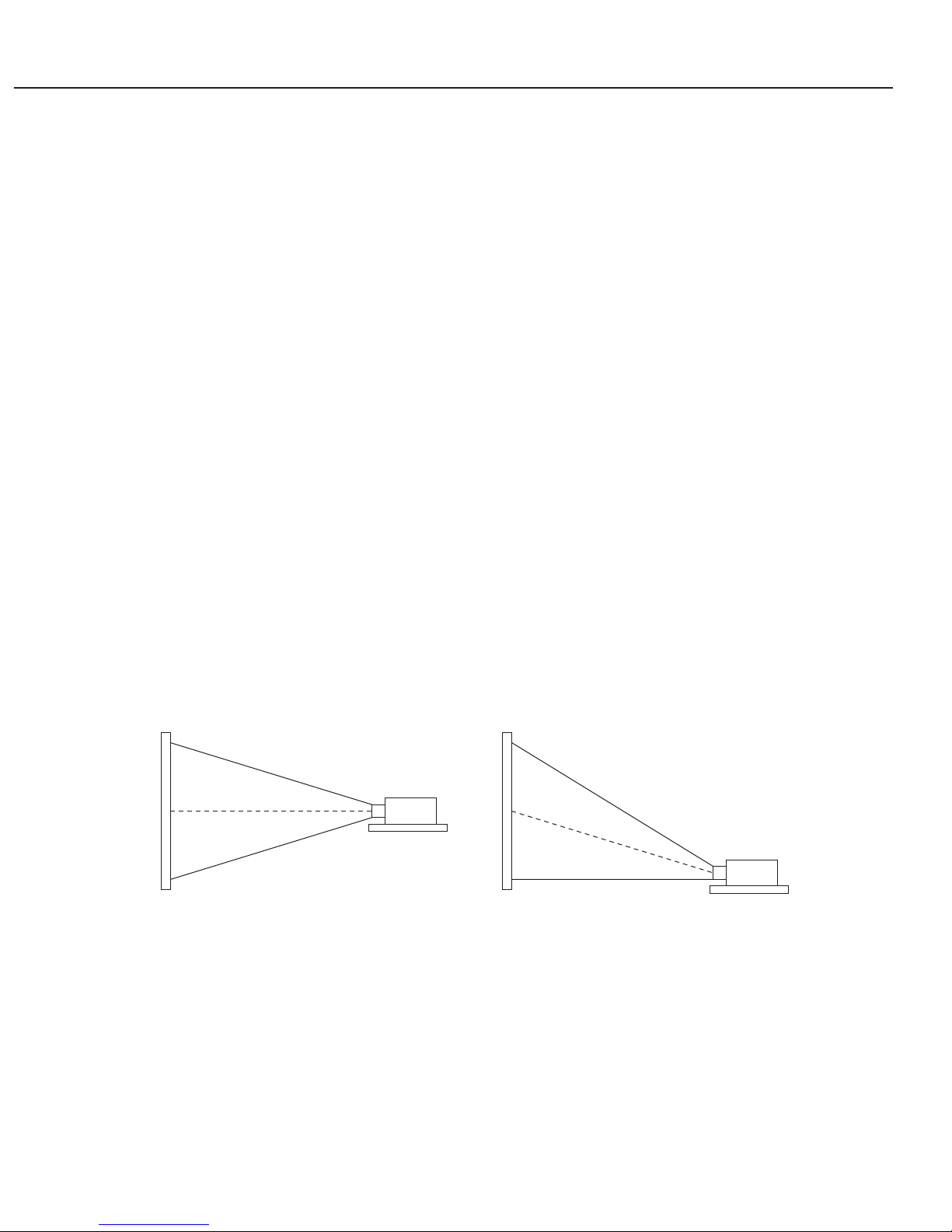
Fig. 1-2
When the lens is shifted to the maximum, the projection screen moves upwards by
approx. 50%. (The screen size is unchanged.)
The projector can be installed more flexibly by combining lens shift with replacement
lenses.
When the ratio is 1:1 When the lens shift is maximized
Part 1: General Information
1-8
Part 1: General Information
1-9
● Automatic fan control system
When the temperature sensor detects a low temperature, the fan speed is reduced
automatically to suppress fan noise, achieving 37dB.
The temperature sensor is located near the air inlet to improve response and optimize
speed.
● Easy lamp replacement mechanism (Canon replacement lamp LV-LP13)
The user can replace the lamp easily.
There is a lamp replacement lid on the rear, and the lamp can be removed just by
removing two screws.
● User cleaning air filter mechanism
The user can replace the air filter easily.
If the air filter become clogged with dust particles, it may result in internal heat build
up. To prevent this, clean the filter regularly.
* Before cleaning the air filter, stop the projector and remove the power plug from the
outlet.
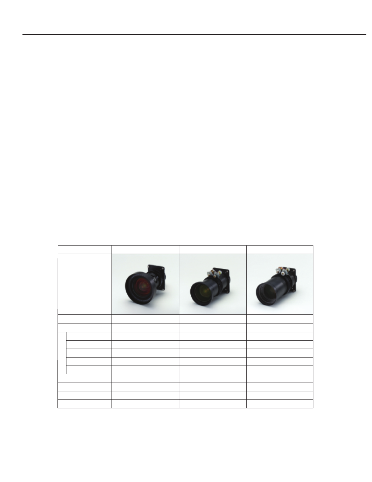
4.7 Replacement Lenses
• LV-IL01, ultra wide angle lens
• LV-IL02, wide angle zoom lens
• LV-IL03, long focus zoom lens
* The projection distance is approximate.
* The ultra wide angle lens (LV-IL01) is mainly designed for rear projection and
assumed to be used with "lens shift U/D ratio of 1:1" for ultra wide angle projection.
If the lens is shifted from the center, the image may be distorted.
LV-IL01 LV-IL02 LV-IL03
22.33 mm 34.3 – 48.02 mm 63.5 – 111.5 mm
Focal length
F2.5 F2.5 –3.06 F2.03 – 2.89
Aperture ratio
0.63 m 0.98 – 1.4 m 1.78 – 3.31 m
40 type
0.97 m 1.5 – 2.15 m 2.7 – 5.0 m
0
60 type
1.63 m 2.54 – 3.65 m 4.7 – 8.5 m
100 type
3.3 m 5.14 –7.4 m 9.4 – 17.1 m
200 type
14.97 m 7.75 – 11.1 m 14.2 – 25.7 m
300 type
1:1 1:1 to 20:1 1:1 to 20:1Lens shift
1.5 kg 1.7 kg 1.8 kg
Weight
170 mm 193 mm 217 mm
Length
ø130 mm ø99 mm ø99.5mm
Outer diameter
Projection distance
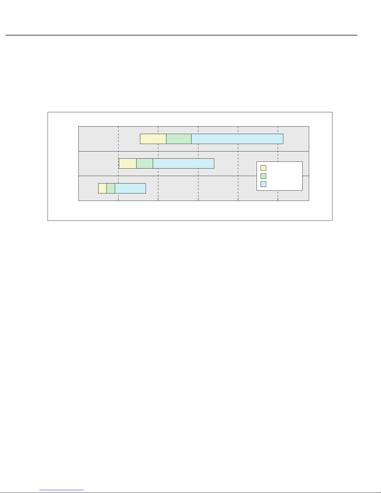
● Guideline for use
Use the appropriate lens for a combination of projector installation position and
screen size.
• See the figure below for the standard lens, LV-IL02 (wide angle zoom lens) and LV-
IL03 (long focus zoom lens).
Fig. 1-3
For example, use a long focus lens to project an image to a 200 type screen
installed at a distance of 12m.
• LV-IL01 (ultra wide zoom lens) can be used for front projection. If it is installed for
front projection, the projector overlaps with the center of the screen. Therefore, it
should be used for rear projection.
Short focus
Standard
Long focus
Projection distance and lens
300 type
200 type
100 type
0 5 10 15 20 25
Projection distance [m]
Part 1: General Information
1-10

5. CONNECTION DIAGRAM
5.1 Connection to the computer: See the attached sheet
(Owner's Manual, page 12).
5.2 Connecting to the video equipment: See the attached sheet
(Owner's Manual, page 13).
Part 1: General Information
1-11

6. SETTING-UP THE PROJECTOR
6.1 Positioning the projector: See the attached sheet
(Owner's Manual, page 9).
6.2 Installation precautions: See the attached sheet
(Owner's Manual, page 8).
Part 1: General Information
1-12

7. SUPPORTED COMPUTER SYSTEM MODE
See the attached sheet (Owner's Manual, page 26).
Part 1: General Information
1-13


Part 2
Repair
Information

Part 2: Repair Information
2-1
1. SAFETY INSTRUCTIONS
The following precautions must be observed during servicing and inspection.
Observe all safety precautions.
Comply with all caution and safety-related notes provided on the cabinet back, cabinet
bottom, inside the cabinet, on the chassis or components, as well as the precautions
shown in the instruction manual during servicing.
Avoid electric shock.
Since an AC voltage is applied to the chassis for the set, touching the chassis during
power-on may cause electric shock. When service is performed during power on, use an
insulation transformer, wear protective gloves, and remove the plug during parts
replacement. As there are high-voltage areas inside the projector, handle it with care
when the power is on.
Use specified parts.
The parts of the set have safety properties, such as inflammability and voltage
withstand. Therefore, use replacement parts with the same characteristics as the
original ones. The critical components for safety are indicated by mark in the
schematic diagram and parts list must be replaced by the recommended parts.
Reinstall parts and wires in their original positions.
Insulating materials, such as tubes and tape, are used and some components are
installed over a PC board for safety. Reinstall internal wires with clamps so that they do
not touch any heat-generating or high-voltage parts.
Safety c
heck after service
Verify that service locations are not deteriorated and all removed screws, parts and
wires are installed in their original positions. In addition, perform the following test to
ensure safety.
Insulation resistance test method
Remove the plug from the electric outlet and press the power switch. Using a 500V
insulation resistance tester (or a multimeter if any insulation resistance tester is not
available), check that the insulation resistance between each terminal of the plug and
external exposed connector (external speaker connector, remote control connector, AV
input/output connector, etc.) is 1Mohm or higher
. If not, the set must be inspected and
repaired.
Components indicated by mark in the parts list and the schematic diagram designate components in
which safety can be of special significance. It is, therefore, particularly recommended that the
replacement of there parts be made by exactly the same parts. Using unspecified parts may worsen
failure or cause fire or electric shock.
Eye damage may result from directly viewing the light produced by the lamp used in this equipment.
Always turn off the lamp before opening the cover.
Never turn the power on without the lamp to avoid electric shock or damage of the devices since the
stabilizer generates high voltages (15kV - 25kV) at its starts.
Since the lamp is very high temperature during units operation replacement of the lamp should be done at
least 45 minutes after the power has been turned off, to allow the lamp cool-off.
Precautions for servicing
Part 2: Repair Information
2-2
2. CIRCUIT PROTECTIONS
This projector is equipped with the following circuit protections to operate in safety. If
the abnormality occurs inside the projector, it will automatically turn off by operating
one of the following protection circuits.
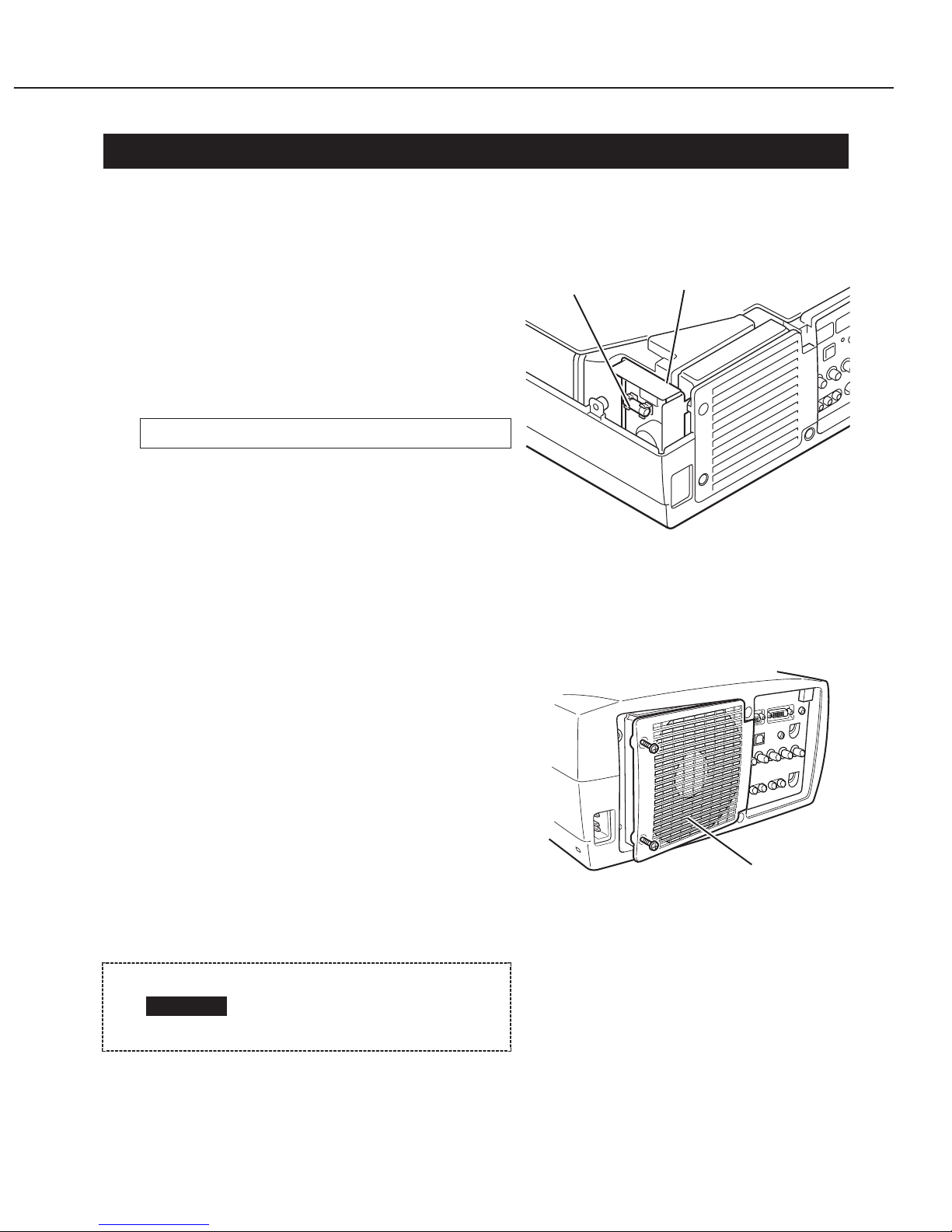
2.1 Fuse
The fuse is located inside of the projector.
When either the LAMP indicator or the
READY indicator is not illuminated, a fuse
may be opened. Check the fuse according to
the following steps. The specified fuse should
be used as follows;
[How to replace the fuse]
1. Remove the cabinet top according to step
1 of "Service (Mechanical Disassembles)".
2. Remove the fuse from fuse holder.
To install the fuse, take reversed step in the above.
2.2 Thermal Switch
When the internal temperature of the
projector reaches near 90˚C, the thermal
switch (SW905) turns off the AC main power
supply automatically.
(Check the resistance between the terminals
of the thermal switch by using a tester. If it is
open, the thermal switch may be in
operative.)
Reset the thermal switch according to the
following procedure.
[How to reset the thermal switch]
1. Remove the cabinet top according to step
1 of "Service (Mechanical Disassembles)".
2. Press the reset button on the thermal switch.
Fuse Part No. DY4-6319-000 (250V 6.3A)
Before pressing the reset
button, disconnect the AC
cord from the projector.
CAUTION
Fig. 2-2
Fig. 2-1
Fuse
Filter unit
Lamp cover
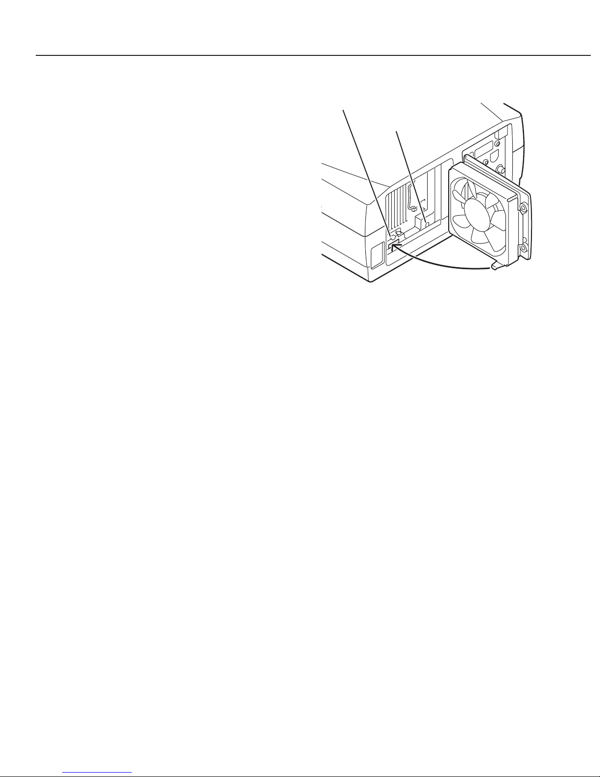
2.3 Interlock Switch
The interlock switch (SW902) cuts AC
power when the lamp cover is removed. If
the lamp cover is opened to replace the
lamp, the projector does not start. Reinstall
the lamp cover.
2.4 Warning Temperature and Power Failure Protection
The TEMP WARNING indicator flashes red and the projector will automatically turn off
when the internal temperature of the projector exceeds the normal temperature or when
stopping cooling fans or when the internal power supply lines are failed. Check the
following possible causes and wait until stopping the TEMP WARNING indicator
flashing.
[Possible causes]
• Air filter is clogged with dust particles. Remove dust from the air filter.
• Ventilation slots of the projector are blocked. In such an event, reposition the
projector so that ventilation slots are not obstructed.
• Check if projector is used at higher temperature place (Normal operating temperature
is 5 to 35˚C)
If the TEMP WARNING indicator still continues to flash, there may be defects on
cooling fans or power supply circuits. Please check fan operation and power supply lines
referring to the "Power Supply Lines Chart".
Part 2: Repair Information
2-3
Fig. 2-3
Interlock switch
Thermal switch
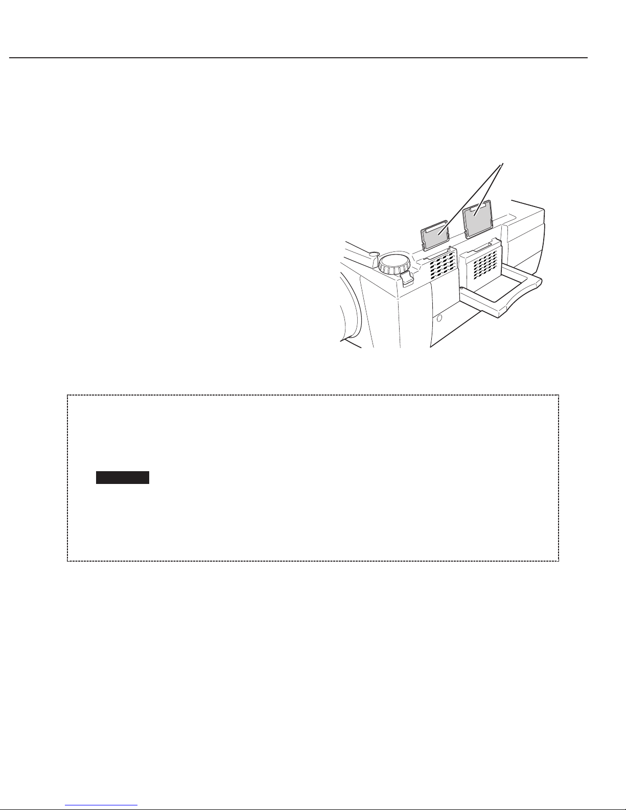
2.5 Air Filter Care and Cleaning
The removable air filter prevents dust from accumulation on the surface of the
projection lens and projection mirror. Should the air filter become clogged with dust
particles, it will reduce the cooling fan's effectiveness and may result in internal heat
build up and reduce the life of the
projector.
To clean up the air filter, follow the
cleaning procedure below:
1. Turn the power off, and disconnect the
AC power cord from the AC outlet.
2. Turn the projector up side down and
remove the air filter by pulling its latches
upward.
3. Clean the air filter with a brush.
4. Replace the air filter properly. Make
sure that the air filter is fully inserted.
Part 2: Repair Information
2-4
Do not operate the projector with the air filter removed. It may result in
the malfunction of the projector.
We recommend to avoid dusty, smoky place for operating the projector.
The dust is stuck on the LCD panel and the mirror, and it may spoil the
fine picture image.
Using in dusty place may cause the picture of poor quality.
When using under the dusty or smoky conditions, dust may accumulate
on the LCD panel and lens inside it, and may resultantly be projected on
the screen together with the picture.
When the above symptoms are noticed, please clean up the LCD panel
and lens according to the "Cleaning Method".
CAUTION
Fig. 2-4
Air filter
3. SERVICE (MECHANICAL DISASSEMBLES)
Mechanical disassemble should be made by following procedures in numerical order.
The following steps show the basic procedures, therefore unnecessary step may be
ignored.
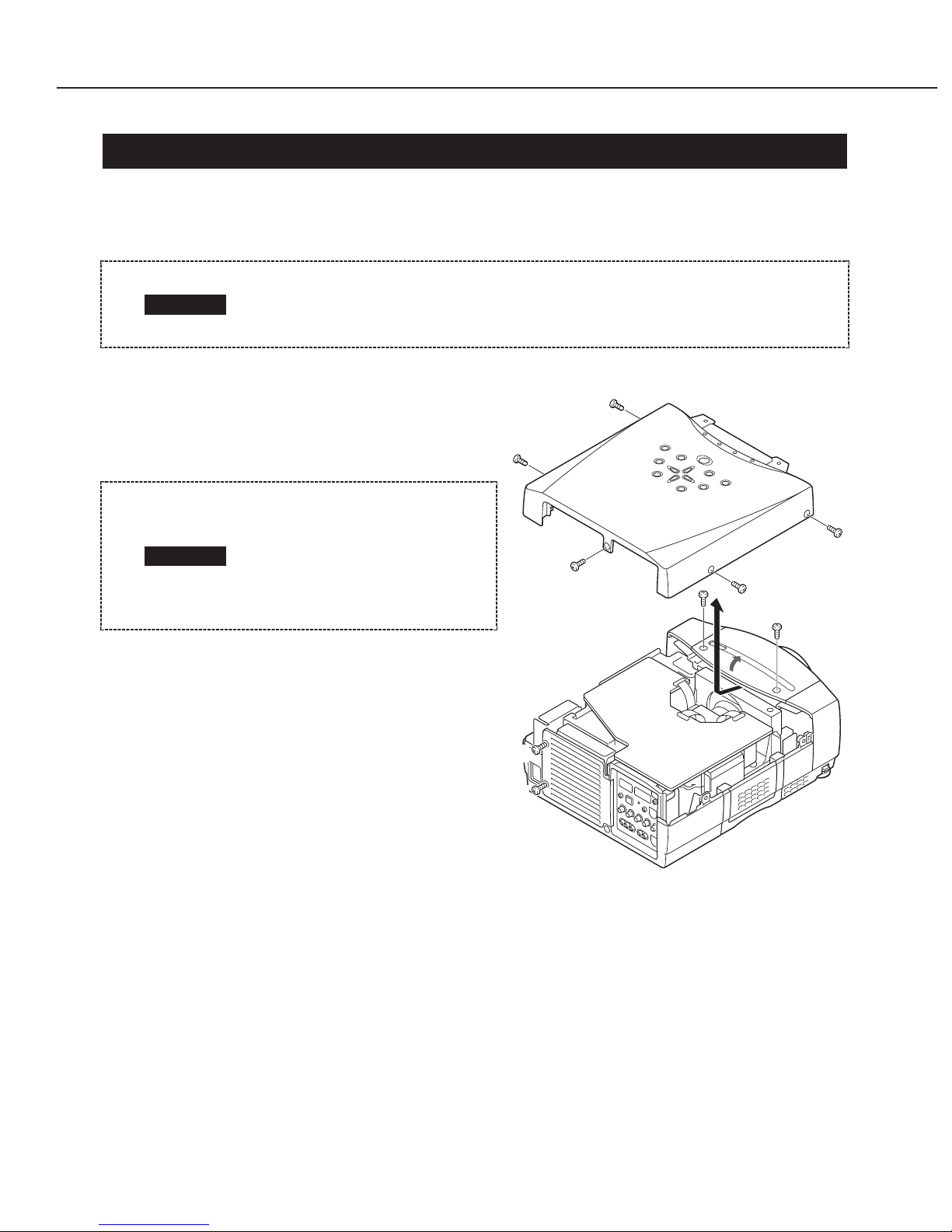
3.1 Cabinet Top Removal
1. Remove 5 screws A and 2 screws B,
loosen 2 screws C, and remove the
cabinet top.
Part 2: Repair Information
2-5
The parts and screws should be placed exactly in the same position as
the original, otherwise it may cause loss of performance and product
safety.
CAUTION
Fig. 2-5
When only the front cabinet
top is removed, screws A
need not be removed.
Remove 2 screws B and the
front lens cover to remove
the front cabinet top.
CAUTION
C
B
A
A
A
A
B
A
C
 Loading...