

Page 1

LR1
SERVICE
MANUAL
Canon
Page 2

QY8-1367-000
REVISION 0
COPYRIGHT 1999 CANON INC. CANON LR1 1299 AB 0.02-0 PRINTED IN JAPAN (IMPRIME AU JAPON)
DEC. 1999
Page 3

1299 AB 0.02-0
Page 4
Page 5

Application
This manual has been issued by Canon Inc. for qualified persons to learn technical theory, installation,
maintenance, and repair of products. This manual covers all localities where the products are sold. For
this reason, there may be information in this manual that does not apply to your locality.
Corrections
This manual could include technical inaccuracies or typographical errors due to improvements or
changes in the products. When changes occur in applicable products or in the content of this manual,
Canon will release technical information as the need arises. In the event of major changes in the
contents of this manual over a long or short period, Canon will issue a new editions of this manual
The following paragraph does not apply to any countries where such provisions are
inconsistent with local law.
Trademarks
The product names and company names described in this manual are the registered trademarks of the
individual companies.
Copyright
This manual is copyrighted with all rights reserved. Under the copyright laws, this manual may not be
copied, reproduced or translated into another language, in whole or in part, without the written consent
of Canon Inc., except in the case of internal business use.
Copyright 1999 by Canon Inc.
CANON INC.
BJ Printer Technical Support Dept. 21
16-1, Shimonoge 3-chome, Takatsu-ku, Kawasaki, Kanagawa 213-8512, Japan
This manual has been produced on an Apple Power Macintosh 7300/180 personal computer and OKI
MICROLINE 803 PSIIV laser beam printer; artworks of printing films were printed on Agfa SelectSet
Avantra 25. All page layouts, logos, and parts-list data were saved with Canon Optical Disc Subsystem
mo-5001S™ and Optical Disc Cartridge mo-502M™, and Interface Kit mo-IF2™ for Macintosh. All
graphics were produced with MACROMEDIA FREEHAND™ 7.0J. All documents and all page layouts were
created with QuarkXpress™ 3.3 Japanese version.
Page 6
I
I. ABOUT THIS MANUAL
This manual is divided into five sections, and contains information required for serving the
unit.
Part 1: Product Specifications
This section contains outlines and product specifications of the unit.
Part 2: Maintenance
This section explains how to maintain the unit. Descriptions and adjustment of
assembly/disassembly and verification methods after assembly/disassembly are
included.
Part 3: Operation
This section explains how to operate the unit properly. Operation procedures for service
modes are explained.
Part 4: Troubleshooting
This section explains how to find out possible causes of troubles and units/parts to be
replaced. It is divided into two parts: troubleshooting by error indications and by
symptoms.
Part 5: Appendix
This section includes block diagrams of the unit and information to technically
understand the hardware (applied for new techniques only). This section also includes
pin arrangements.
Sufficient information regarding assembly/disassembly is not given in this
manual. Refer to the illustrations in the separate
Parts Catalog
.
Product
Outline
Maintenance
Operation Troubleshooting Appendix
Page 7

II. TABLE OF CONTENTS
Page
Part 1:
PRODUCT OUTLINE
1 - 1 1. PRODUCT OUTLINE
1 - 1 1.1 Product Outline
1 - 2 1.2 Features
1 - 3 2. SPECIFICATIONS
1 - 3 2.1 Printer Specifications
1 - 3 2.1.1 Printer specifications
1 - 4 2.1.2 Printer life
1 - 4 2.2 Paper Specifications
1 - 4 2.2.1 Paper sizes and weights
1 - 4 2.2.2 Paper types and handling
1 - 5 2.2.3 Printable area
1 - 6 2.3 BJ Cartridge Specifications
1 - 7 2.4 Interface Specifications
1 - 7 2.4.1 Parallel interface
1 - 7 2.4.2 Serial interface
1 - 8 2.5 Printer Drivers
1 - 9 3. PACKING
1 -10 4. INSTALLATION
1 -10 4.1 Installation Location
1 -10 4.2 Installation Procedure
1 -10 4.2.1 Connecting the centronics interface cable
1 -10 4.2.2 Connecting the USB interface cable
1 -10 4.2.3 Connecting to a power supply
1 -11 5. NAMES AND FUNCTION OF PARTS
1 -12 6. PARTS CODE LIST
Part 2: MAINTENANCE
2 - 1 1. PERIODIC REPLACEMENT PARTS AND MAINTENANCE
2 - 1 1.1 Periodic Replacement Parts
2 - 1 1.2 Consumables
2 - 1 1.3 Periodic Maintenance
2 - 2 2. DISASSEMBLY AND REASSEMBLY
2 - 2 2.1 Tools
2 - 3 2.2 Cautions for Disassembly and Reassembly
2 - 3 2.2.1 Cautions for ink stains (ink path/ink mist)
2 - 4 2.2.2 Damage by static electricity
2 - 5 2.2.3 Preparation for transportation
2 - 6 2.3 Disassembly and Reassembly
2 - 6 2.3.1 Removing plastic parts
2 - 6 2.3.2 Removing and installing tap screws
2 - 6 2.3.3 Cable positions
2 - 6 2.3.4 Deformation of spur tips
2 - 7 2.3.5 Feed gear cautions
2 - 7 2.3.6 Installing and removing the upper case unit
2 - 8 2.3.7 Positioning the MODE switch
2 - 8 2.3.8 Installing and removing the home position sensor
2 - 9 2.4 Applying Grease
2 - 9 2.5 Adjustments and Settings After Disassembly and Reassembly
2 - 9 2.5.1 Adjustments
2 -10 2.6. Spur Cleaner
II
Page 8

Page
2 -10 2.6.1 Usage
2 -11 3. OPERATION CHECK AFTER DISASSEMBLY AND ASSEMBLY
2 -11 3.1 Check Procedure
Part 3: OPERATION
3 - 1 1. PRINTER OPERATION FUNCTIONS
3 - 1 1.1 Status Indications
3 - 2 1.1.1 Status indicators
3 - 3 1.1.2 Error description
3 - 4 1.1.3 Ink-low indicator
3 - 5 1.1.4 BJ status monitor (Used only when connected to a computer)
3 - 6 1.2 Operation With a Computer
3 - 6 1.2.1 Function settings with the printer driver
3 - 7 1.3 Operation From the Printer Itself
3 - 7 1.3.1 Cleaning and head refreshing
3 - 8 1.3.2 Printing the nozzle check pattern
3 - 8 1.3.3 Resetting the dot counter
3 - 9 1.3.4 Cleaning the pick-up roller
3 - 9 1.3.5 Auto power on/off setting
3 -10 1.3.6 Mode switch
3 -11 2. SERVICE-RELATED FUNCTION
3 -11 2.1 Service Mode Operations
3 -12 2.2 Printing the EEPROM Data
3 -13 2.3 Setting the Waste Ink Amount
Part 4: TROUBLESHOOTING
4 - 1 1. TROUBLESHOOTING ACCORDING TO ERROR DISPLAY
4 - 1 1.1 Initial Flow Chart
4 - 4 1.2 Error List
4 - 5 1.3 Troubleshooting Errors
4 -16 2. TROUBLESHOOTING BY SYMPTOMS
4 -16 2.1 Troubleshooting By Symptoms
Part 5: APPENDIX
5 - 1 1. TECHNICAL REFERENCE
5 - 1 1.1 Description of Paper-feed Section
5 - 1 1.1.1 Construction of paper-feed section
5 - 1 1.1.2 Pick-up section
5 - 2 1.1.3 Transport section
5 - 2 1.1.4 Paper delivery section
5 - 3 1.1.5 Remaining paper indication function
5 - 3 1.1.6 Pick-up retry function
5 - 3 1.1.7 The form alignment function
5 - 4 1.2 Purge Section
5 - 4 1.2.1 Cleaning function
5 - 5 1.2.2 Description of Purge Section
5 - 7 1.3 Description of Carriage Section
5 - 7 1.3.1 BJ cartridge mounting function
5 - 7 1.3.2 Carriage drive control
5 - 8 1.4 Electronic Circuit Description
5 - 8 1.4.1 Printer block diagram
5 - 8 1.4.2 Power source line block diagram
5 - 9 1.4.3 USB interface
III
Page 9

Page
5 -10 1.4.4 Automatic interface switching
5 -10 1.4.5 Detection functions
5 -11 1.5 BJ Cartridge Description
5 -11 1.5.1 BJ cartridge and ink cartridge configuration
5 -11 1.5.2 BJ cartridge construction
5 -11 1.5.3 BJ cartridge printing drive control
5 -11 1.5.4 BJ cartridge identification
5 -12 1.5.5 Printing mode list
5 -13 2. CONNECTOR LOCATIONS AND PIN ARRAY
5 -13 2.1 Control Board
5 -18 2.2 Operation Panel Board
5 -19 2.3 Sensor Board
5 -19 2.4 Pick-up Roller Position Sensor Board
5 -20 2.5 BJ Cartridge
5 -21 2.6 Carriage Motor
5 -21 2.7 Paper-Feed Motor
5 -22 2.8 Pick-up Motor
5 -23 2.9 Circuit Diagram
IV
Page 10

III. ILLUSTRATION INDEX
Page
Part 1:
PRODUCT OUTLINE
1 - 1 Figure 1 - 1 Exterior of Printer
1 - 2 Figure 1 - 2 Possible System Configurations
1 - 5 Figure 1 - 3 Printable Area
1 - 9 Figure 1 - 4 Packing
1 -10 Figure 1 - 5 Installation Space
1 -11 Figure 1 - 6 Parts Names and Major Functions
Part 2: MAINTENANCE
2 - 3 Figure 2 - 1 Ink Path
2 - 4 Figure 2 - 2 Parts Exposed to Ink Mist
2 - 6 Figure 2 - 3 Spurs
2 - 7 Figure 2 - 4 Feed Gear Cautions
2 - 7 Figure 2 - 5 Installing and Removing the Upper Case Unit
2 - 8 Figure 2 - 6 MODE Switch Positioning
2 - 8 Figure 2 - 7 Installing and Removing the Home Position Sensor
2 - 9 Figure 2 - 8 Applying Grease
2 -10 Figure 2 - 9 Spur Cleaner
2 -10 Figure 2 -10 Set the Spur Cleaner
Part 3: OPERATION
3 - 1 Figure 3 - 1 Operation Panel
3 - 5 Figure 3 - 2 BJ Status Monitor (Sample)
3 - 6 Figure 3 - 3 Printer Driver Utilities (Sample)
3 - 7 Figure 3 - 4 Printer Buttons
3 - 8 Figure 3 - 5 Printing the Nozzle Check Pattern (Sample BC-11e)
3 -12 Figure 3 - 6 EEPROM Data Printout (sample)
3 -13 Figure 3 - 7 Waste Ink Absorber (50% of capacity)
Part 5: APPENDIX
5 - 1 Figure 5 - 1 Paper-Feed Path
5 - 1 Figure 5 - 2 Pick-up Section
5 - 2 Figure 5 - 3
5 - 3 Figure 5 - 4 Indicating the Remaining Amount of Paper
5 - 3 Figure 5 - 5 Fixing Skewed Paper
5 - 5 Figure 5 - 6 Purge Section
5 - 6 Figure 5 - 7 Wiping Operation
5 - 7 Figure 5 - 8 Carriage Section Structure
5 - 8 Figure 5 - 9 Block Diagram
5 - 8 Figure 5 -10 Power Source Line Block Diagram
5 - 9 Figure 5 -11 USB Data Transfer
5 - 9 Figure 5 -12 NRZI
5 -10 Figure 5 -13 Sensor Locations
5 -11 Figure 5 -14 Cartridge Configuration
5 -11 Figure 5 -15 Nozzle Array
5 -13 Figure 5 -16 Control Board
5 -13 Figure 5 -17 Printer Diagram
5 -18 Figure 5 -18 Operation Panel Board
5 -19 Figure 5 -19 Sensor Board
5 -19 Figure 5 -20 Pick-up Roller Position Sensor Board
5 -20 Figure 5 -21 BJ Cartridge
V
Page 11

Page
5 -21 Figure 5 -22 Carriage Motor
5 -21 Figure 5 -23 Paper-Feed Motor
5 -22 Figure 5 -24 Pick-up Motor
VI
Page 12

IV. TABLE INDEX
Page
Part 1:
PRODUCT OUTLINE
1 -12 Table 1- 1 PARTS CODE
Part 3: OPERATION
3 - 2 Table 3- 1 STATUS INDICATORS
Part 4: TROUBLESHOOTING
4 - 4 Table 4- 1 ERROR DISPLAY
Part 5: APPENDIX
5 - 4 Table 5- 1 INK CONSUMPTION DURING CLEANING
5 -10 Table 5- 2 DETECTION FUNCTIONS
5 -12 Table 5- 3 PRINTING MODES AND DRIVE METHOD
5 -17 Table 5- 4 HEAD INSTALLATION STATUS AND SIGNAL DETECTION
VII
Page 13

Page 14

Part 1
PRODUCT
OUTLINE
Page
1 - 1 1. PRODUCT OUTLINE
1 - 1 1.1 Product Outline
1 - 2 1.2 Features
1 - 3 2. SPECIFICATIONS
1 - 3 2.1 Printer Specifications
1 - 4 2.2 Paper Specifications
1 - 6 2.3 BJ Cartridge Specifications
1 - 7 2.4 Interface Specifications
1 - 8 2.5 Printer Drivers
1 - 9 3. PACKING
1 -10 4. INSTALLATION
1 -10 4.1 Installation Location
1 -10 4.2 Installation Procedure
1 -11 5. NAMES AND FUNCTION OF PARTS
1 -12 6. PARTS CODE LIST
Page 15

Page 16
1. PRODUCT OUTLINE
1.1 Product Outline
This is Canon’s first bubble-jet printer for use with a set top box (STB).
The design is a complete departure from conventional printers geared for personal
computers. The printer is designed to resemble an AV component to match the living
room interior.
It also has a MODE SELECTION switch, ink-low warning, and other functions which
are required as a non-PC printer. The large-capacity ink cartridges also make ink
cartridge replacements less frequent.
1-1
LR1
Part 1: Product Outline
Product
Outline
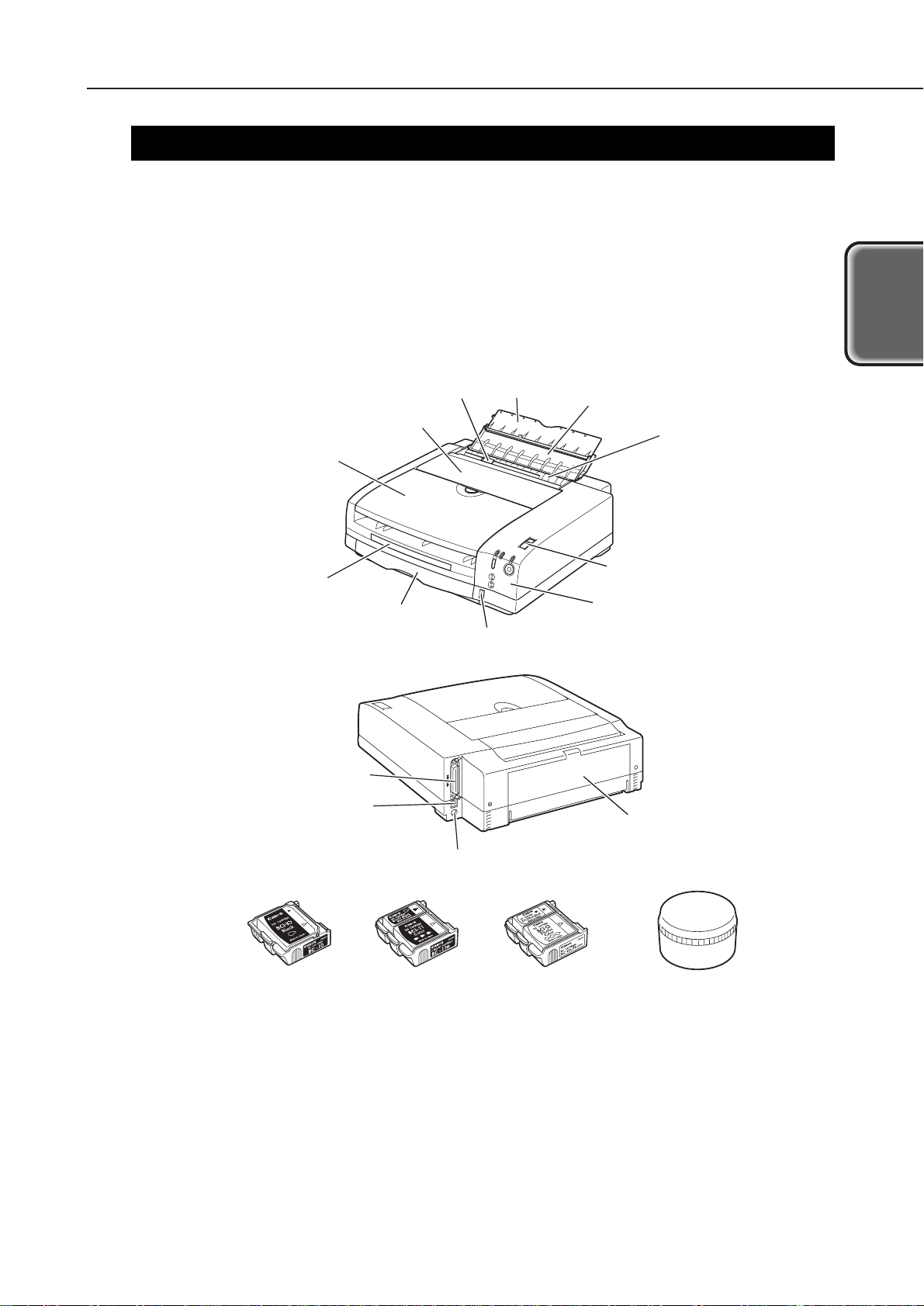
Manual-feed slot
Manual-feed tray
Extension tray
Cartridge cover
Paper delivery cover
Paper delivery tray
Parallel interface connector
USB interface connector
Power connector
Black Color Photo
Storage box
BJ cartridge
Manual-feed guide
Operation panel
MODE switch
Paper cassette
Remaining paper indication window
Rear cover
Figure 1-1 Exterior of Printer
Page 17
1.2 Features
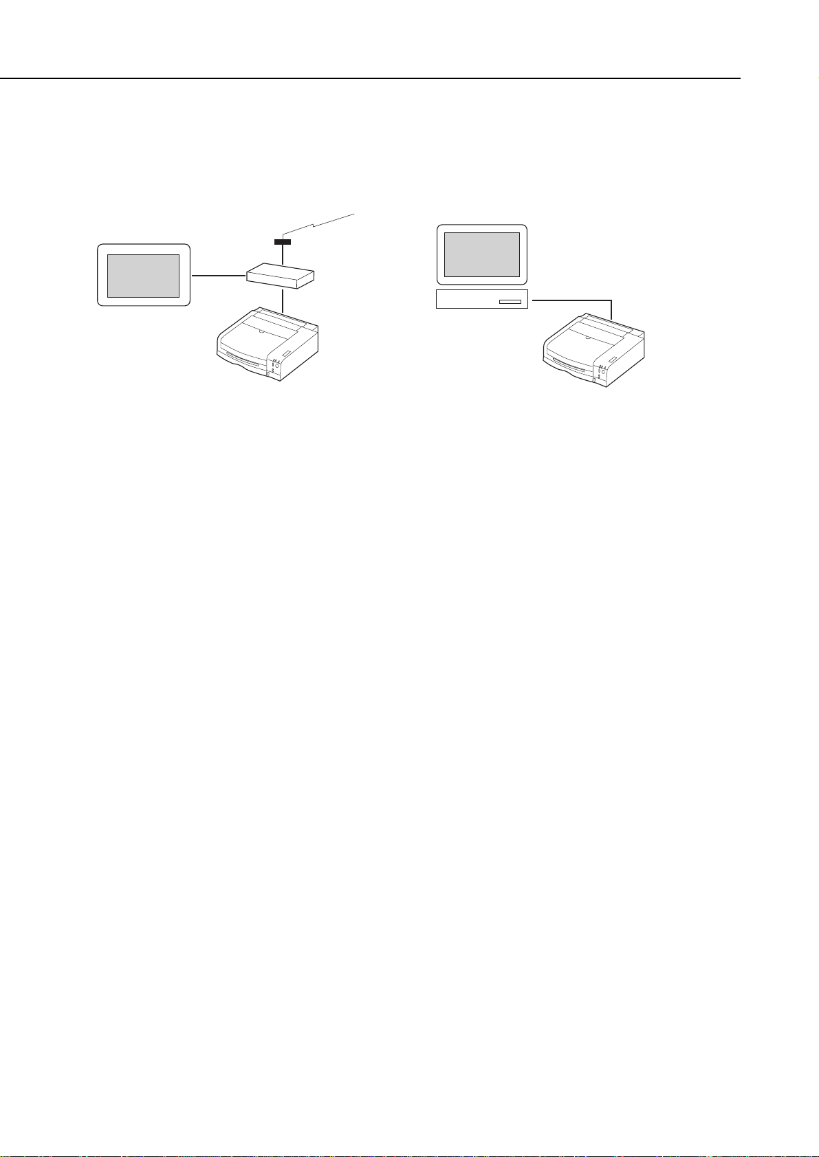
1) The printer is connected to the TV via the STB to enable images from the Internet to
be printed. It can also be used as a PC printer.
2) By using a paper cassette and the operation panel on the front of the printer, frontend operation is easy.
3) The printer uses three types of BJ cartridges: Black, color, and photo color.
The black and color cartridges use large-capacity ink cartridges to make ink cartridge
replacement less frequent.
Black BJ cartridge BC-10 (optional): 128-nozzle head with detachable ink cartridge
Color BJ cartridge BC-11e: 136-nozzle head (64-nozzles for Bk and 24
nozzles each for Y, M, and C) with detachable
ink tank and ink-drop modulation technology
Photo Color BJ cartridge BC-12e (optional):
136-nozzle head (64-nozzles for Bk and 24
nozzles each for Y, M, and C) with detachable
ink cartridge and ink-drop modulation
technology
Ink Cartridge BCI-10 Black: For BC-10 Black
Ink Cartridge BCI-17 Black: For BC-10 large-capacity Black
Ink Cartridge BCI-11 Black: For BC-11e Black
Ink Cartridge BCI-11 Color: For BC-11e Color (YMC integrated)
Ink Cartridge BCI-18 Black: For BC-11e large-capacity Black
Ink Cartridge BCI-18 Color: For BC-11e large-capacity Color (YMC integrated)
Ink Cartridge BCI-12 Black: For BC-12e Photo Black
Ink Cartridge BCI-12 Color: For BC-12e Photo Color (YMC integrated)
4) The remaining ink amount is calculated with the dot counter. An
INK-LOW
indicator
is also provided.
5) Bitmap fonts for the Internet are built-in for high-quality and quick text output.
Part 1: Product Outline
LR1
1-2
With a STB (set top box).
TV
Modem
Internet
STB
LR1
With a personal computer.
Personal computer
LR1
Figure 1-2 Possible System Configurations
Page 18

2. SPECIFICATIONS
2.1 Printer Specifications
2.1.1 Printer specifications
1-3
LR1
Part 1: Product Outline
Product
Outline
Type
Paper Feed System
Resolution
Throughput
(Reference only)
Printing Direction
Max. Print Width
Line Feed Speed
Interface
Cassette Capacity
Manual Feed Tray
Capacity
Detection Function
Operating Noise
Ambient Conditions
Power Source
External
Dimensions
Weight
Certification
Desk-top serial color printer, non-PC printer for STB
Automatic feed (cassette)/Manual feed (manual feed tray)
360 × 720 dpi (Max. resolution)
* Catalog specification.
Unidirectional (automatically selected according to the print data)
203 mm
Approx. 136 ms/line: 9.03 mm (128/360 inch) carriage return
USB and IEEE 1284-standard, 8-bit parallel (Compatible/Nibble)
Plain paper: 5 mm max. (Approx. 50 sheets at 75 g/m2)
1 sheet
Cartridge cover-open detection: Provided
BJ cartridge detection: Provided
BJ cartridge identification: Provided
Ink-low detection sensor: Provided
Waste ink capacity detection: Provided
Paper width detection: None
Approx. 45 dB (A): Sound pressure level conforms to ISO 9296.
During operation: Temperature 5°C-35°C (41°F-95°F)
Humidity 10%-90% RH (No condensation)
During non-operation: Temperature 0°C-35°C (32°F-95°F)
Humidity 5%-95% RH (No condensation)
Power voltage/frequency: 100-240 VAC 50/60 Hz
Power consumption: During printing: Approx. 30 W
During standby: Approx. 2 W
Soft power off: Approx. 2 W
Approx. 365mm W × 364mm D × 110 mm H
Approx. 4.0 kg (excluding BJ cartridge)
Radio wave interference: FCC, SISPR 22, CE Mark
Electrical safety: UL, CSA, IEC, GS, FIMKO, SEMCO, AS/NZS,
CCIB, SISIR,
EI, NEMKO, Korean Electric Commerce
Environmental: Energy Star, Blue Angel
BC-10 Black Cartridge
Black Text (PC Magazine)
New monochrome pattern (E)
BC-11e Color Cartridge
New color pattern (E)
BC-12e Photo Cartridge
Full Address Printing
High-speed
3.5 ppm
4.1 ppm *
1.9 ppm *
-
High-quality
-
1.0 ppm
0.3ppm
0.1 ppm *
Standard
3.2 ppm
3.9 ppm *
1.6 ppm *
-
Page 19

2.1.2 Printer life
The printer’s life shall be until any of the following conditions is attained:
(1) A total of 12,000 sheets are printed with the1,500-character standard pattern in
black ink
(2) A total of 6,000 sheets are printed with the color printing standard pattern at 7.5%
duty per color
(3) A total of 2,000 sheets are printed with photographic standard patterns
(4) Five years of operation elapses
2.2 Paper Specifications
2.2.1 Paper sizes and weights
(1) Paper sizes
A4, B5, A5, letter, envelope (Com #10/DL-size)
(2) Weight
64-105 g/m2for cassette feeding
2.2.2 Paper types and handling
* Paper dedicated to BJ printers.
Note 1: The printing side of the paper is stacked face-down in the cassette.
Note 2: Only A4 or letter-size paper can be fed from the paper cassette.
Part 1: Product Outline
LR1
1-4
Type
Plain paper
Plain paper
for Color BJ
High-quality
paper
Photo glossy
paper
Glossy film
Transparency
film
Back print
film
Banner
T-shirt
transfer
Photo glossy
card
Envelope
Size
A4/LTR
A4/B5/LTR/A5
A4/LTR
A4/LTR
A4/LTR
A4/LTR
A4/LTR
A4/LTR
A4/LTR
A4/LTR
120 mm × 216 mm
241 mm × 105 mm
220 mm × 110 mm
LC-301*
HR-101*
GP-301*
HG-101*
CF-102*
BF-102*
BP-101*
TR-201*
FM-101*
Com #10
DL-size
Feed method
Cassette
Manual
Cassette
Manual
Cassette
Manual
Manual
Manual
Manual
Manual
Manual
Manual
Manual
Manual
Capacity
Approx. 5 mm or less
(Approx. 50 sheets of 75 g/m
2
weight)
1 sheet
Approx. 5 mm or less
(Approx. 50 sheets of 75 g/m
2
weight)
1 sheet
Approx. 5 mm or less
(Approx. 40 sheets)
1 sheet
1 sheet
1 sheet
1 sheet
1 sheet
1 sheet
1 sheet
1 sheet
1 sheet
1 sheet
Page 20

2.2.3 Printable area
1-5
LR1
Part 1: Product Outline
Product
Outline
:Recommended printing area.
: Possible printing area.
3.0mm
7.0mm
3.4mm: A4/A5/B5/Postcard
6.4mm: LTR
3.4mm: A4/A5/B5/Postcard
6.3mm: LTR
22mm
A4/A5/B5/Letter/Postcard Size
3.0mm
7.0mm
6.4mm
Envelopes
22mm
22mm
22mm
(COM#10: 31.4mm)
(DL size: 10.4mm)
Figure 1-3 Printable Area
Page 21

2.3 BJ Cartridge Specifications
*1 : The number of sheets per ink cartridge
*2 : 1,500-character standard pattern.
*3 : 7.5% duty per color (using standard pattern).
*4 : Average 16.7% duty per color.
*5 : 7.5% duty per color (calculated values by ink volume used).
Part 1: Product Outline
LR1
1-6
Construction
Head
Ink colors
Ink
cartridge
Weight
Service Life
Printable
Sheets*
1
Black BJ Cartridge
BC-10
Detachable ink cartridge
128 nozzles
(Vertical array)
Bk (128 nozzles × 1)
Bk
BCI-10 Black
BCI-17 Black
(large-capacity)
26 g
(with BCI-10 installed)
Approx. 3,000 sheets*
2
Approx. 170 sheets
(BCI-10)*
2
Approx. 270 sheets
(BCI-17)*
2
Color BJ Cartridge
BC-11e
Detachable ink cartridge
136 nozzles
(Vertical array)
Bk (64 nozzles × 1)
C, M, Y (24 nozzles × 3)
Bk, C, M, Y
BCI-11 Black
BCI-11 Color
BCI-18 Black
(large-capacity)
BCI-18 Color
(large-capacity)
29 g
(with BCI-11 installed)
Approx. 2,000 sheets*
3
Color : Approx. 30 sheets
(BCI-11)*
3
Black : Approx. 25
sheets (BCI-11)*
3
Color : Approx. 50 sheets
(BCI-18)*
3
Black : Approx. 40
sheets (BCI-18)*
3
Photo BJ Cartridge
BC-12e
Detachable ink cartridge
136 nozzles
(Vertical array)
Bk (64 nozzles × 1)
C, M, Y (24 nozzles × 3)
Photo Bk, Photo C,
Photo M, Y
BCI-12 Black (Photo)
BCI-12 Color (Photo)
29 g
(with BCI-12 installed)
Approx. 200 sheets*
4
Approx. 20 sheets*
5
Page 22

2.4 Interface Specifications
2.4.1 Parallel interface
1) Interface type
IEEE 1284 parallel interface
2) Data transfer method
8-bit parallel transfer (Compatibility mode and nibble mode supported)
3) Signal level
Input
“Low” level: 0.0 V to +0.8 V
“High” level: +2.0 V to +5.0 V
Output
“Low” level: 0.0 V to +0.4 V
“High” level: +2.4 V to +5.5 V
4) Input/Output
+5 V pull-up for all signals
5) Interface cable
Cable: Twisted-pair, double-shielded cable, 2.0 m or shorter
Must conform to IEEE 1284.
Wire material: AWG (American Wire Gauge) No. 28 or higher
6) Interface connector
On printer: Amphenol 57-40360 or equivalent
On cable: Amphenol 57-30360 or equivalent
7) I/O signal and pin array
For details, see
“Part 5: CONNECTOR LOCATION AND PIN ARRAY” on page 5-13
.
2.4.2 Serial interface
1) Interface type
USB (Universal Serial Bus conforming to USB Specification Revision 1.0)
2) Data transfer method
Control transfer
Bulk transfer
3) Signal level
-Data, +Data
Difference input sensitivity: +0.2 V (Min.)
“H” level output voltage: +2.8 V to +3.6 V
“L” level output voltage: +0.0 V to +0.3 V
Vcc
“H” level input voltage: +2.0 V to +5.5 V
“L” level input voltage: +0.0 V to +0.8 V
4) Input/Output
3.3 V pull-up for +Data signal
5) Interface cable
Cable: Twisted-pair, shielded cable, 5.0 m or shorter
Must conform to USB.
Wire material: AWG (American Wire Gauge) No. 28 or higher
6) Interface connector
On printer: USB with series-B receptacle
On cable: USB with series-B plug
7) I/O signal and pin array
For details, see
“Part 5: CONNECTOR LOCATION AND PIN ARRAY” on page 5-13
.
1-7
LR1
Part 1: Product Outline
Product
Outline
Page 23

2.5 Printer Drivers
The compatibility between printer drivers and interface ports is shown below.
●●: Compatible, ▲▲: Compatible under certain conditions, ✕: Incompatible
* For USB, compatibility is assured only with personal computers preinstalled with
Windows 98.
Part 1: Product Outline
LR1
1-8
Windows 95/98
Windows NT4.0
Windows 2000
Macintosh
Printer Driver
Parallel I/F
●●
✕
✕
✕
USB I/
▲▲*
✕
✕
✕
Page 24
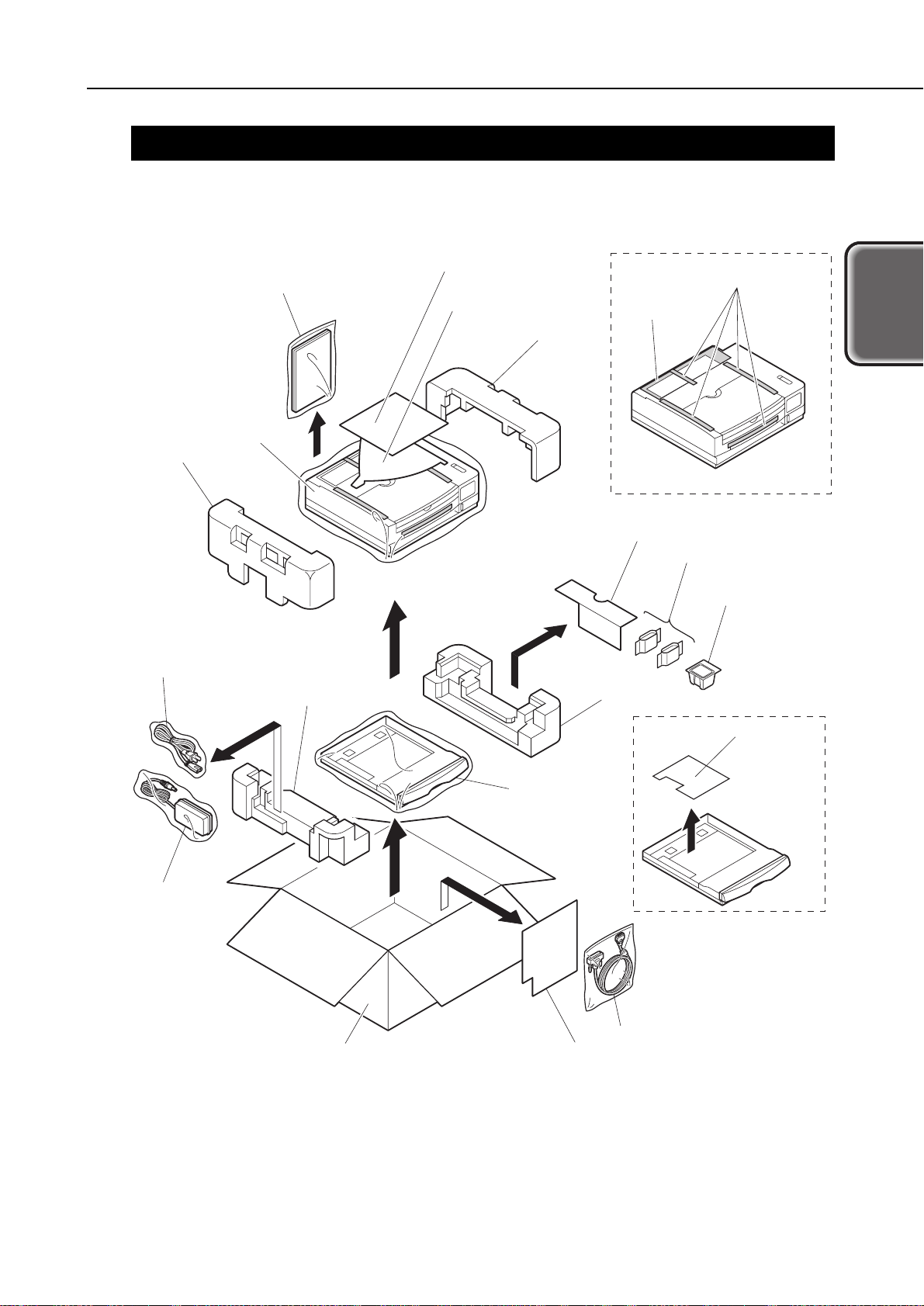
3. PACKING
After opening the package, make sure all the items below have been included.
1-9
LR1
Part 1: Product Outline
Product
Outline
Box
BJ cartridge
Packing
Packing
Packing
Packing
Ink cartridges
Packing for accessories
Packing for accessories
Power cord
Paper cassette
Cassette
protective
packing
AC adapter
Printer
Quick sheet
Interface cable
Manuals
Tape
Quick guide
Protective
sheet
Figure 1-4 Packing
Page 25
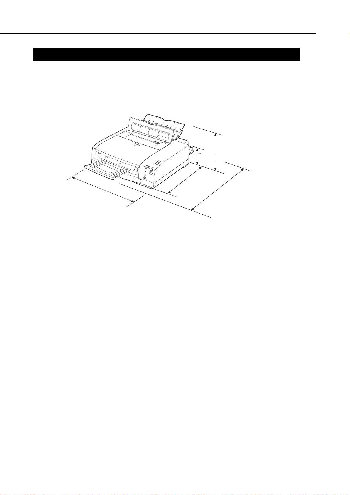
4. INSTALLATION
For installation details, see the User’s Manual.
4.1 Installation Location
For optimum use, place the printer where there is enough space. The printer’s external
dimensions are shown below.
4.2 Installation Procedure
To prevent an electric potential difference between the computer and printer, first
connect the interface cable, then connect the AC plug into an AC power outlet.
4.2.1 Connecting the centronics interface cable
1) Make sure the printer and computer’s power is off.
2) Connect the interface cable to the printer’s interface connector. Lock the
connection with the cable’s connector clips.
3) Connect the other end of the interface cable to the computer and lock the
connection.
4.2.2 Connecting the USB interface cable
1) Connect the interface cable to the printer’s interface connector. Lock the
connection with the cable’s connector clips. It is unnecessary to turn off the printer
or computer before connecting cables. The cable can be connected while their
powers are turned on.
2) Connect the other end of the interface cable to the computer and lock the
connection.
4.2.3 Connecting to a power supply
1) Connect the AC plug of the power cable to an AC power outlet and the DC plug of
the AC adapter to the printer.
2) Press the printer’s
POWER
button to turn on the printer. First, all the indicators
on the printer will light. Then the
POWER
indicator will light and the
BUSY
indicator will blink during the initialization operation. After the initialization ends,
the
BUSY
indicator will turn off. If a BJ cartridge has not been installed, the
ERROR
indicator will light and the beeper will sound three times. The carriage will also
move to the cartridge replacement position.
Part 1: Product Outline
LR1
1-10
Approx.365 mm
Approx.185.5 mm
Approx.559.5 mm
Approx.110 mm
Approx.
364 mm
Figure 1-5 Installation Space
Page 26

5. NAMES AND FUNCTION OF PARTS
The names and major functions of parts are shown below.
1-11
LR1
Part 1: Product Outline
Product
Outline
POWER
button
Press to turn on/off the power
and print the test pattern.
Operation panel
POWER
indicator (Green)
OFF: Power is off.
ON: Power is on.
INK-LOW
indicator
Lights when the remaining ink
amount is low.
Cartridge cover
Open this cover when
replacing the BJ cartridge.
• When this cover is opened,
the carriage moves to the
cartridge replacement
position.
• Also, if the cartridge is being
loaded and this cover is left
open for 10 min. or longer,
the carriage returns to the
home position.
• If this cover is opened during
printing, the printing will
stop. Closing the cover will
resume the printing.
Mode switch
If the connected STB has a
mode switching function, it
can be set with this switch.
It cannot be used when a
computer is connected.
Manual-feed tray
Load this tray during manual
paper feeding.
Paper check window
Displays the amount of
paper remaining in the
cassette.
Parallel interface connector
Connector for connection
to a computer.
Paper delivery tray
After printing, the paper is
discharged to this tray.
Paper cassette
Load with plain paper or
HR-101. (only for A4/LTR)
DOT COUNTER RESET
button
After replacing the BJ
cartridge or ink cartridge,
press this button to reset
the ink dot counter.
If the ink dot counter is
not reset, the ink-low
indicator will not be
accurate.
USB interface connector
Connector for connection
to a computer.
Rear cover
This is opened to fix paper jams
or to execute the pick-up roller
cleaning.
RESUME/
CLEAN
LOW INK
BUSY
COLOR
BLACK
POWER
Paper delivery cover
Prevents dust, etc., from
adhering to the discharged
paper.
Power connector
Connector for connection to a
AC adapter.
BUSY
indicator (Green)
OFF: Standby
ON: Printing in progress
or printing data
being received.
Blinks:During
initialization or
cleaning.
Cover is open.
ERROR
indicator (Orange)
OFF: Normal status
Lit or blinking:
An error has occurred and
printing is not possible.
RESUME
button
This cancels user-resolvable
errors. Also, it is used to
execute cleaning, and pick-up
roller cleaning.
Extension tray
Figure 1-6 Parts Names and Major Functions
Page 27
6. PARTS CODE LIST
A list of printer parts, consumables, and optional equipment are listed below.
* Items included with LR1: BC-11e, BCI-18 Bk, BCI-18 Color, AD 360U, power cable,
parallel interface cable.
Part 1: Product Outline
LR1
1-12
Table 1-1 PARTS CODE
Item
Printer
BJ cartridge
Ink cartridge
Cartridge storage box
Universal Adapter
Power cable
Black
Color
Photo
Black
Black (large-capacity)
Black
Color
Black (large-capacity)
Color (large-capacity)
Photo black
Photo color
-
-
-
Designation
LR1*
BC-10
BC-11e
BC-12e Photo
BCI-10Bk
BCI-17Bk
(large-capacity)
BCI-11Bk
BCI-11Color
BCI-18Bk
(large-capacity)
BCI-18Color
(large-capacity)
BCI-12Bk
BCI-12Color
SB-11
AD360U
-
Product Code
Q30-3220
F45-0631
F45-1321
F45-1751
F47-0751
F47-2721
F47-0761
F47-0771
F47-2731
F47-2741
F47-2751
F47-2761
Q70-4120
Q70-3839
Q70-3980
Page 28

Part 2
MAINTENANCE
Page
2 - 1 1. PERIODIC REPLACEMENT PARTS AND MAINTENANCE
2 - 1 1.1 Periodic Replacement Parts
2 - 1 1.2 Consumables
2 - 1 1.3 Periodic Maintenance
2 - 2 2. DISASSEMBLY AND REASSEMBLY
2 - 2 2.1 Tools
2 - 3 2.2 Cautions for Disassembly and Reassembly
2 - 6 2.3 Disassembly and Reassembly
2 - 9 2.4 Applying Grease
2 - 9 2.5 Adjustments and Settings After Disassembly and Reassembly
2 -10 2.6. Spur Cleaner
2 -11 3. OPERATION CHECK AFTER DISASSEMBLY AND ASSEMBLY
2 -11 3.1 Check Procedure
Page 29

Page 30

1.
PERIODIC REPLACEMENT PARTS AND MAINTENANCE
1.1 Periodic Replacement Parts
1.2 Consumables
1.3 Periodic Maintenance
2-1
LR1
Part 2: Maintenance
Maintenance
Level
User
Service
personnel
Consumables
None
BJ Cartridge
Ink Cartridge
LargeCapacity
Ink Cartridge
For Black BJ
Cartridge
BC-10
BCI-10
BCI-17
For Color BJ
Cartridge
BC-11e
Bk: BCI-11 Bk
Color: BCI-11 Color
Bk: BCI-18 Bk
Color: BCI-18 Color
For Photo BJ
Cartridge
BC-12e
Bk: BCI-12 Bk
Color: BCI-12 Color
None
Level
User
Service personnel
Replacement Parts
None
None
Level
User
Service personnel
Periodic Inspections
None
None
Page 31

2. DISASSEMBLY AND REASSEMBLY
2.1 Tools
Tools required for disassembly and reassembly are listed below.
Part 2: Maintenance
LR1
2-2
Ordinary Tools
Phillips screwdriver
Blade screwdriver
Needle-nosed pliers
Tweezers
Flat brush
Remarks
For the removal and installation of screws.
For the removal of plastic parts.
For the removal and installation of springs.
For the disconnection and connection of flexible cables, etc.
For applying grease.
Special Tools (Part No.)
Grease MOLYKOTE PG-641
(CK-0562-000)
Spur Cleaner (QY9-0055-000)
Remarks
To be applied on the specified parts (see
page 2-9
).
For cleaning the spurs (see
page 2-10
).
Page 32

2.2 Cautions for Disassembly and Reassembly
2.2.1 Cautions for ink stains (ink path/ink mist)
During servicing, be careful not to touch the ink path and get ink stains on the
printer, work table, and your hands and clothing.
The ink path includes the BJ cartridge’s ink cartridge supply inlet, the BJ cartridge’s
ink filter, the ink nozzles and maintenance jet receptacle, head cap, wiper, and waste
ink absorber.
Although the ink does not contain anything harmful to humans, it does
contain organic solvents.
Black ink: Glycerin 56-81-5, ethylene glycol 107-21-1, isopropyl alcohol
107-21-1
Color ink: Isopropyl alcohol 67-63-0
Photo ink: Glycerin 56-81-5, ethylene glycol 107-21-1, isopropyl alcohol
67-63-0
Be careful not to get the ink in your mouth or eyes.
If ink gets into your eyes, wash with lots of water and see a doctor. If you
consume a large amount of ink orally, see a doctor promptly.
Since the ink contains dyes, it will permanently stain clothing and other
materials.
2-3
LR1
Part 2: Maintenance
Maintenance
Waste ink absorber
Pump
Cap
Wiper
Ink path
Maintenance jet receptacle
Figure 2-1 Ink Path
Page 33

The BJ cartridge ejects ink onto the paper to print. After a long period of time or
heavy-duty use, ink mist created by loose ink droplets and ink bouncing off by the
paper will soil the platen, inside the cartridge cover, and around the purge section.
These soiled parts can soil the paper and your hands and clothing. To prevent this,
use a soft, damp cloth to wipe these parts clean.
When cleaning the purge section, be careful not to touch the cap or wiper
section.
2.2.2 Damage by static electricity
Due to the rubbing of clothing, static electricity can build up within the human body.
Static electricity can damage electrical components or alter the electrical
characteristics of components.
Never touch the contacts on the carriage and the BJ cartridge.
Handle the control board, sensor board or operation panel board with care not to
break them by static electricity.
Part 2: Maintenance
LR1
2-4
Figure 2-2 Parts Exposed to Ink Mist
Platen section
Purge section
Purge section
Check point !
Page 34

2.2.3 Preparation for transportation
While moving or transporting the printer, either leave the BJ cartridge in the printer
or keep it in the storage box. This is to prevent the ink from leaking and the BJ
cartridge’s ink nozzles from drying up.
(1) Carrying the printer
Before carrying the printer while the BJ cartridge is still installed, follow the
procedure below.
1) Turn off the printer by pressing the
POWER
button.
2) Check that the BJ cartridge is at the capping position (right end of printer). If it is
not at the capping position, turn the printer on and off by the
POWER
button so that
the carriage is moved to the capping position.
3) Disconnect the interface cable.
4) Disconnect the AC adapter’s DC plug from the printer.
Disconnect the AC adapter’s AC plug from the power outlet.
If you turn off the power by disconnecting the AC adapter or if you carry or
transport the BJ cartridge without putting it in the storage box, ink may
leak and the nozzles may dry up.
(2) Transporting the printer
Before transporting the printer, follow the procedure below.
1) Follow the procedure above for
“(1) Carrying the printer”
to turn off the printer and
disconnect the interface cable and AC adapter.
2) Pack the printer and AC adapter in their original packaging.
If you do not have the original packaging, use enough shock-absorbing material to
pack the printer.
2-5
LR1
Part 2: Maintenance
Maintenance
Page 35

2.3 Disassembly and Reassembly
Cautions for disassembling and reassembling the printer are stated below.
As for the disassembly procedure, refer to the
Parts Catalog
. The illustrations in the
Parts Catalog
are numbered according to the order of disassembly.
2.3.1 Removing plastic parts
The printer has many plastic parts. When disassembling the printer, be careful not to
break or bend the plastic hooks. For details on disassembly and reassembly, refer to
the
Parts Catalog
.
Some plastic parts contain glass fiber to improve the rigidity for better
precision. Since these parts are less flexible, their plastic hooks are
especially easy to break. During disassembly, do not exert excessive force
on plastic parts with a screwdriver or other instrument.
2.3.2 Removing and installing tap screws
The printer uses tap screws to fasten the upper and bottom cases, the control board
and bottom case, the pick-up unit and bottom case unit, and the chassis platen unit
and bottom case. The removed tap screws will have residue from the mold in which
the internal thread was made. Since the residue may crush the screw threads, clean
off the residue from the tap screws before re-installing or use new tap screws.
2.3.3 Cable positions
Lay the cables connecting the motors, sensors, and control board according to the
stipulated position.
For positioning the cables, refer to the
Parts Catalog
.
2.3.4 Deformation of spur tips
Be careful not to deform the spur tips.
The spur contacts the paper after the printing.
If the spur’s tips are deformed, the contact area with the paper will become larger,
increasing the amount of ink on the paper transferring onto the spur tips which will
soil paper with dotted lines.
Part 2: Maintenance
LR1
2-6
Spurs section
Figure 2-3 Spurs
Page 36

2.3.5 Feed gear cautions
When disassembling or reassembling the printer, do not touch the gears of the at
paper feeding section. Note that even a slight scratch on the gears will cause irregular
paper feeding during high-quality printing.
2.3.6 Installing and removing the upper case unit
Before installing or removing the upper case unit, the paper delivery tray must be
removed.
2-7
LR1
Part 2: Maintenance
Maintenance
Paper feed
gear
Paper feed
double gear
Figure 2-4 Feed Gear Cautions
1
2
Paper delivery tray
Upper case unit
Figure 2-5 Installing and Removing the Upper Case Unit
Page 37

2.3.7 Positioning the MODE switch
The position of the MODE switch on the upper cover must match the switch on the
control board. Otherwise, the cover cannot be attached properly.
2.3.8 Installing and removing the home position sensor
The home position sensor cannot be installed or removed when the carriage is at the
home position. Move the carriage away from the home position before installing or
removing the home position sensor.
Part 2: Maintenance
LR1
2-8
Match the position of the Mode switch
to the position of the control board.
Mode switch
The switch on the control board
Mode switch in
the A position
Mode switch in
the B position
Mode switch
Switch on the control board
Figure 2-6 MODE Switch Positioning
Home position sensor
1
2
Figure 2-7 Installing and Removing the Home Position Sensor
Page 38

2.4 Applying Grease
The places where grease is applied are shown below.
Only one type of grease is to be used: PG-641 (CK-0562).
Use a flat brush to apply grease thinly and evenly.
To disassemble and assemble the printer, refer to the
Parts Catalog
.
When applying grease, be careful not to get any grease on the wiper and
cap.
2.5 Adjustments and Settings After Disassembly and Reassembly
2.5.1 Adjustments
(1) User Level
None.
(2) Service personnel Level
* To clear and set the EEPROM, refer to
“Part 3: 2.1 Service Mode Operations” on page 3-10
.
2-9
LR1
Part 2: Maintenance
Maintenance
Carriage shaft
Carriage guide
Figure 2-8 Applying Grease
Timing
After control board replacement
After printer base unit replacement
Adjustment
EEPROM setting*
EEPROM clear*
Time Required
2 min.
2 min.
Tools Required
None
None
Page 39

2.6. Spur Cleaner
If the tips of spurs become dirty with ink, spur marks can be left on the print images.
In such case, clean the spurs by using the spur cleaner (QY9-0055-000). The spur
cleaner can be used until it loses its intended effect.
2.6.1 Usage
1) Moisten the fabric part of the spur cleaner with approx. 5 cc of water.
Moisten the fabric with water, as shown below, so that the fabric absorbs enough
water from end to end, especially the areas that will contact the spurs.
Be careful not to moisten the fabric with too much water. In case too much water
is used, there is a possibility that water will be squeezed from the spur cleaner
when passing through the paper feed roller, spread inside the printer, and cause
failure.
2) Turn the power on.
3) Set the spur cleaner.
Open the manual feed tray and set the spur cleaner with the fabric-affixed part of
the cleaner face-up and to the top.
The spur cleaner is fed and stops at the print start position.
4) Feed the spur cleaner.
Press the
RESUME
button, and release it after the beeper sounds once. The spur
cleaner is delivered.
5) Repeat procedures 3) and 4) approx. 5 times in case of heavy soiling.
6) Remove the moisture remaining in the paper feeding path.
With a single sheet of plain paper set in the manual feed tray, repeat procedure 4)
several times until the water is completely removed from the paper path.
Part 2: Maintenance
LR1
2-10
Fabric (white-colored)
Spur cleaner
Part moistened with water
Be careful that the water
is absorbed by the fabric
from end to end.
Transparent film
Fabric (white-colored)
Spur cleaner
Figure 2-9 Spur Cleaner
Figure 2-10 Set the Spur Cleaner
Page 40

3. OPERATION CHECK AFTER DISASSEMBLY AND ASSEMBLY
3.1 Check Procedure
After disassembly and reassembly, follow the procedure below to check the printer’s
operation.
1) After repairs
Check that the printer can print out the EEPROM data properly. For the procedure,
see
“Part 3: 2.1 Service Mode Operations” on page 3-10
.
2) After replacing the control board and printer base unit
After replacing the control board and printer base unit, check the following:
After control board replacement The ROM version in the list of EEPROM data
must be the correct one.
In the list of EEPROM data, the total waste ink
amount must be about the same percentage as
in the waste ink absorber.
The nozzle check pattern must be able to be
printed from the printer driver.
After printer base unit replacement In the list of EEPROM data, the total waste ink
amount must be cleared to 0%.
*1: To print out the list of EEPROM settings, see
“Part 3: 2.1 Service Mode Operations” on
page 3-10
.
*2: To set or clear the total waste ink amount, see
“Part 3: 2.1 Service Mode Operations”
on page 3-10
.
2-11
LR1
Part 2: Maintenance
Maintenance
Page 41

Part 2: Maintenance
LR1
2-12
This page intentionally left blank
Page 42

Part 3
OPERATION
Page
3 - 1 1. PRINTER OPERATION FUNCTIONS
3 - 1 1.1 Status Indications
3 - 6 1.2 Operation With a Computer
3 - 7 1.3 Operation From the Printer Itself
3 -11 2. SERVICE-RELATED FUNCTION
3 -11 2.1 Service Mode Operations
3 -12 2.2 Printing the EEPROM Data
3 -13 2.3 Setting the Waste Ink Amount
Page 43

Page 44

1. PRINTER OPERATION FUNCTIONS
The printer’s operation functions include status indications and printer control via a
personal computer or via the printer’s operation panel and operation from the printer
itself.
1.1 Status Indications
The printer has indicators to indicate the printer status.
The printer indicates an error with a green
POWER
indicator, a green
BUSY
indicator,
an orange
ERROR
indicator, and a certain number of beeper sounds.
The remaining ink amount is indicated by the
INK-LOW
indicator.
3-1
LR1
Part 3: Operation
Operation
RESUME/
CLEAN
LOW INK
BUSY
COLOR
BLACK
POWER
INK-LOW
indicator
ERROR
indicator
RESUME
button
POWER
button
POWER
indicator
BUSY
indicator
Figure 3-1 Operation Panel
Page 45

1.1.1 Status indicators
1) Normal Status
Refer to the following
“Table 3-1 STATUS INDICATORS”
.
2) Error Status
2-1) Error display for user-recoverable errors
When a user-resolvable error occurs, the
ERROR
indicator either turns on or blinks
and the beeper sounds a certain number of times. By closing the cartridge cover
and pressing the
RESUME
button, the beeper sounds a certain number of times to
indicate which error has occurred and the error is canceled.
2-2) Error display for user-unrecoverable errors
When a user-unrecoverable error occurs, the
POWER
indicator,
BUSY
indicator, or
ERROR
indicator blinks and the beeper sounds a certain number of times to indicate
which error has occurred.
* The
BUSY
indicator turns on when there is receiving data.
Part 3: Operation
LR1
3-2
Table 3-1 STATUS INDICATORS
Indicator State
Power
(Green)
On
On
On
Off
Busy
(Green)
Off
Blinking
On
Off
Status
During power on.
During initialization and busy, cartridge
replacement, cleaning operation, and cartridge
cover open.
During printing.
During power on and standby.
Error
(Orange)
Off
Off
Off
Off
Status
User-recoverable errors
Paper-feed error
Paper jam error
Cartridge not-loaded error
Cartridge mismatch error
Failed manual feed warning
Cartridge replacement
auto-completion warning
Cartridge overheating warning
Waste ink full warning
User-unrecoverable errors
ROM error
RAM error
No-cartridge error
Home position error
Waste ink full error
Internal temperature sensor error
Automatic correction error
Head overheating error
EEPROM error
Power
On
On
On
On
On
On
On
On
Blinking
Blinking
Blinking
Blinking
Blinking
Blinking
Blinking
Blinking
Blinking
Busy
Off
Off
Off
Off
Off
Off
Off
Off*
Blinking
Blinking
Blinking
Blinking
Blinking
Blinking
Blinking
Blinking
Blinking
Error
On
On
On
On
Blinking
Blinking
Blinking
Blinking
Blinking
Blinking
Blinking
Blinking
Blinking
Blinking
Blinking
Blinking
Blinking
Beeper Sounds
1
2
3
4
1
3
4
5
1
2
3
4
5
6
7
8
11
Page
Page 4-11
Page 4-11
Page 4-13
Page 4-13
Page 4-10
Page 4-15
Page 4-8
Page 4-5
Page 4-5
Page 4-5
Page 4-13
Page 4-6
Page 4-5
Page 4-5
Page 4-6
Page 4-8
Page 4-5
Page 46

1.1.2 Error description
User-recoverable errors
1) Paper-feed error
The paper is not fed during the paper-feed operation.
2) Paper jam error
The paper cannot be delivered even when the paper delivery operation is executed for
584.2 mm (23 inches).
3) Cartridge not-loaded error
The cartridge is not loaded in the printer.
4) Cartridge mismatch error
The data sent by the personal computer does not match the installed cartridge.
Open the cartridge cover and install the correct cartridge. The error will then be
canceled. Pressing the
POWER
button to turn the printer on/off will also cancel the
error.
5) Failed manual feed warning
The paper cannot be fed manually with the manual feed tray.
6) Cartridge replacement auto-completion warning
The cartridge replacement mode has been disabled by the printer. Closing the
cartridge cover cancels the error.
7) Cartridge overheating warning
The cartridge temperature is high and the cartridge cover is also open.
8) Waste ink full warning
The total waste ink amount recorded in the EEPROM is close to the full capacity
(99% or higher).
User-unrecoverable errors
9) ROM error
The ROM check failed during initialization.
10) RAM error
The RAM check failed during initialization.
11) No-cartridge error
The printer is unable to detect the BJ cartridge at any position except at the
cartridge replacement position.
12) Home position error
The home position sensor is not working (line disconnected).
The carriage’s home position cannot be detected.
13) Waste ink full error
The total waste ink amount recorded in the EEPROM exceeds the full capacity
(100%).
14) Internal temperature sensor error
The temperature sensor (TH1) on the control board has a malfunction (line
disconnected).
15) Automatic correction error
The home position cannot be detected during printing position correction.
16) Head overheating error
The BJ cartridge temperature is abnormal.
17) EEPROM error
An error occurred during the writing to EEPROM.
3-3
LR1
Part 3: Operation
Operation
Page 47

1.1.3 Ink-low indicator
The printer has an
INK-LOW
indicator to display the remaining ink amount.
No lamps lit: Enough ink remains.
One lamp lit: The large-capacity ink cartridges have less than half (equivalent
to the amount in the standard ink cartridge) the full amount of
ink.
The standard-capacity ink cartridges have little ink remaining.
Two lamps lit: The large-capacity ink cartridge has little ink remaining.
After replacing the ink cartridge, reset the dot counter. If the dot counter
is not reset, the remaining ink amount detected will not be correct. To
reset the dot counter, see
“1.3.3 Resetting the dot counter” on page 3-8
.
Part 3: Operation
LR1
3-4
The BCI-18 Color still has ink.
The BCI-18 Color's remaining ink amount
is half or less.
The BCI-11 Color's/BCI-12 Color has little
ink remaining.
BCI-18 Color has little ink remaining.
The BCI-17 Black/BCI-18 Black's
remaining ink amount is less than half.
The BCI-10 Black/BCI-12 Black has little
ink remaining.
BCI-18 Black has little ink remaining.
COLOR
: off
: lit (Green)
BLACK
COLOR
BLACK
COLOR
BLACK
The BCI-17 Black/BCI-18 Black still has
ink.
Page 48

1.1.4 BJ status monitor (Used only when connected to a computer)
The BJ status monitor indicates the printer’s status and printer progress. It can also
cancel the printing.
The BJ status monitor can be used only when it is connected to a personal computer.
It cannot be used when it is connected to a set top box.
(1) BJ status monitor features
1) Displays the printer’s status and printing progress in real-time with diagrams and
messages.
2) When an error occurs, the error type and solutions are displayed.
3) The type of BJ cartridge installed and ink-low warning are displayed as text and
icons.
4) The current printing operation can be canceled.
(2) BJ status monitor display items
1) Printer name
2) Document name
3) Status: When an error occurs, the error code and solutions are displayed.
4) Start date and time
5) Progress
6) Printed page count
7) Printing canceled
8) Installed cartridge: Cartridge type indicated by an icon.
9) Ink-low warning: The remaining amount of ink for each ink cartridge is displayed
as an icon.
3-5
LR1
Part 3: Operation
Operation
Figure 3-2 BJ Status Monitor (Sample)
Page 49

1.2 Operation With a Computer
When the printer is connected to a personal computer, the printer’s functions can be
set with the exclusive printer driver. The exclusive printer driver cannot be used when
the printer is connected to a set top box.
1.2.1 Function settings with the printer driver
The following utility items can be set or executed with the exclusive printer driver.
1) Cleaning
2) Head refreshing
3) Pick-up roller cleaning
To clean the pick-up roller, feed one cleaning sheet in the cassette to the rear of the
printer. This cleans the paper bits adhering to the pick-up roller.
To clean the pick-up roller, open the rear cover. The cleaning sheet will be delivered
from the rear of the printer.
4) Printing the demo pattern
5) Printing the nozzle check pattern
6) Printer power off
7) Automatic power on/off function setting
8) Status monitor startup
Part 3: Operation
LR1
3-6
Figure 3-3 Printer Driver Utilities (Sample)
Page 50

1.3 Operation From the Printer Itself
The printer has a
POWER
button,
RESUME
button, MODE switch, and
DOT COUNTER
RESET
button.
These printer controls enable “offline operation” while the printer is not connected to a
computer or STB.
1.3.1 Cleaning and head refreshing
While the power is on, hold down the
RESUME
button and release after the beeper
sounds the stipulated number of times. The cleaning will then start. Cleaning can
also be executed from the printer driver’s utility while the printer is connected to a
computer.
3-7
LR1
Part 3: Operation
Operation
MODE
switch
POWER
button
DOT COUNTER RESET
buttons
RESUME
button
Figure 3-4 Printer Buttons
Operation
Cleaning
Head refreshing
Beeper Sounds
2 times
3 times
Page 51

1.3.2 Printing the nozzle check pattern
With the printer off, hold down the
POWER
button and release after the beeper
sounds four times. The nozzle check pattern will then start printing. If any printing
defects show up in this printout, excute the BJ cartridge cleaning. If the printing
defect still persists after cleaning the BJ cartridge or refreshing the head five times or
more, replace the BJ cartridge.
If possible, print out the nozzle check pattern with paper fed from the cassette.
If you must feed the paper manually to print out the nozzle check pattern, follow the
procedure below:
1) Without setting any paper in the manual-feed slot, and the paper cassette try to
print out the nozzle check pattern. A paper-feed error will occur.
2) Insert one sheet of paper into the manual-feed slot, then press the
RESUME
button.
The paper-feed error will be canceled and the nozzle check pattern will be printed.
1.3.3 Resetting the dot counter
After replacing the ink cartridge or BJ cartridge with a new cartridge, follow the
procedure below to reset the dot counter.
1) Open the cartridge cover. The cartridge will move to the center.
2) Check that the ink cartridge whose dot counter is to be reset is installed. (The dot
counter reset will be enabled only for the cartridge installed.)
3) When resetting the dot counter for the black ink cartridge, press the
“BLACK”
COUNTER RESET
button. To reset the dot counter for a color ink cartridge, hold
down the
“COLOR”
button and release when the beeper sounds.
After replacing the ink cartridge or BJ cartridge to a new one, be sure to
reset the dot counter. If the dot counter is reset without the ink cartridge
being replaced or if the dot counter is not reset after the cartridge is
replaced, the remaining ink amount detected will not be correct.
Part 3: Operation
LR1
3-8
Figure 3-5 Printing the Nozzle Check Pattern (Sample BC-11e)
24
24
24
64
24
24
24
24
Printed with the first nozzle.
Printed with the 136th nozzle.
Large and small dot printing
Yellow 24 nozzles
Magenta 24 nozzles
Black 64 nozzles
Cyan 24 nozzles
Printed with the 136th nozzle.
Small dot printing
Printed with the first nozzle.
Page 52

1.3.4 Cleaning the pick-up roller
When dust and paper bits adhere to the pick-up roller, the paper feeding becomes less
efficient. In such a case, use a cleaning sheet to clean the pick-up roller as described
below.
Use the exclusive cleaning sheet included in the pack of high-resolution paper.
1) Put the cleaning sheet in the paper cassette.
Peel off the cleaning sheet’s backing. Lay the sheet with the sticky side facing up.
Set the sticky side toward the claw.
2) Open the rear cover.
3) Hold down the
RESUME
button and release it when the beeper sounds once.
The cleaning sheet will be fed into the printer and discharged out the back of the
printer. The error indicator will light.
4) Take out the cleaning sheet and close the rear cover. Press the
RESUME
button.
You can also clean the pick-up roller with the printer driver if the printer
is connected to a personal computer. See
1.2.1 Function settings with the
printer driver on page 3-6
.
1.3.5 Auto power on/off setting
The printer has an auto power on/off feature.
Upon factory shipment, the printer is set as follows:
Auto power on: Enabled
Auto power off: Enabled, 30 min.
To disable the auto power on/off, hold down the
POWER
button and release after the
beeper sounds the stipulated number of times.
To enable the auto power on/off again, set the function back to the factory setting.
With the power off, hold down the
POWER
button and release after the beeper sounds
seven times. The function will then be returned to the factory shipment setting. Note
that this will also return all other items in the function setting table to the factory
shipment setting.
The auto power on/off setting can also be changed with the printer driver’s utility
while the printer is connected to a personal computer.
3-9
LR1
Part 3: Operation
Operation
Setting
Auto power on: Disabled
Auto power off: Disabled
Beeper Sounds
12 times
13 times
Page 53

The function settings upon factory shipment are shown below.
1.3.6 Mode switch
If the STB connected to the printer has a mode selection switch, you can choose the
mode by the
MODE
switch. The
MODE
switch is not used when the printer is
connected to a computer.
Part 3: Operation
LR1
3-10
Paper Selection
LTR
Smoothing
Disable
Font
Roman
Internal
Character Set
USA
Test Scale
Disable
Reduction
1/1
Font Lock
Disable
Character Set
Italic
Top Margin
8.5mm
Auto Power On
Enable
Input/Download
Buffer
64/23KB
Code Page
PC437
Print Mode
HQ
Auto Power Off
Enable (30 min.)
Automatic Line
Feed
CR=CR
Low Ink Alert
Enable
Page 54

2. SERVICE-RELATED FUNCTION
The printer has a service mode to access service settings and to execute a test printout.
2.1 Service Mode Operations
1) Disconnect the cable of AC adapter from the printer power connector. Open the
cartridge cover.
2) While holding down the
COLOR DOT COUNTER RESET
button and the
BLACK DOT
COUNTER RESET
button and insert the AC adapter’s DC plug into the printer.
3) While holding down the
COLOR DOT COUNTER RESET
button and the
BLACK DOT
COUNTER RESET
button, press the
POWER
button and release the buttons after the
beeper sounds once.
4) Press the
COLOR DOT COUNTER RESET
button the number of times indicated below
to select the function to be executed.
Each time you press the button, the beeper will sound and the indicator will change
to orange or green.
5) After making the selection, press the
BLACK DOT COUNTER RESET
button. The
beeper sounds once and the functions will be executed.
The service mode can be set only when the cartridge cover is open. The
cover sensor detects whether the cartridge cover is open or not.
When the cover sensor lever is up, the cover is detected as closed.
When the cover sensor lever is down, the cover is detected as open.
When you take off the upper case or cartridge cover, the cover sensor lever
will be up. In that case, do step 2 above while pushing down the cover
sensor lever.
3-11
LR1
Part 3: Operation
Operation
Times
7
13
14
15
16
Indicator
Busy (Green)
Busy (Green)
Error (Orange)
Busy (Green)
Error (Orange)
Function
EEPROM reset
EEPROM data printout
Waste ink absorber capacity setting: 25%
Waste ink absorber capacity setting: 50%
Waste ink absorber capacity setting: 75%
Page 55

2.2 Printing the EEPROM Data
The EEPROM records various data such as the settings, total page count of each BJ
cartridge, total waste ink absorption amount, and the dot counter for each ink
cartridge. The data in EEPROM serves as a general guide to how much the printer has
been used.
Part 3: Operation
LR1
3-12
ROM version
Ink dot count
B461---------------Black
B462/B467 -------Color
B467us------------Photo
Total page count
(monochrome/color)
Total waste ink
amount count (ng/%)
Figure 3-6 EEPROM Data Printout (sample)
Page 56

2.3 Setting the Waste Ink Amount
The printer detects “waste ink full” based on the total waste ink absorption amount
recorded in the EEPROM. Thus, after you replace the waste ink absorber, you must
also reset the total waste ink absorption amount.
Also, after replacing the control board, you must reset the new control board’s
EEPROM and set the waste ink absorption amount for the waste ink absorber installed
in the printer base unit.
1) After replacing the control board
Before replacing the control board, visually check the waste ink absorption amount in
the waste ink absorber in the printer base unit.
After replacing the control board, set the waste ink absorption amount you found out
visually to the EEPROM.
2) After replacing the printer base unit (waste ink absorber)
After replacing the printer base unit, set 0% as the waste ink absorption amount to
the EEPROM (EEPROM reset).
The EEPROM contains various data such as the settings, total page count for each BJ
cartridge, total waste ink absorption amount, and the dot counter for each ink
cartridge. When the EEPROM is reset, all those data will be reset as well.
3-13
LR1
Part 3: Operation
Operation
0 % 25 %
50 %
75 %
100 %
Waste ink full error
Waste ink
Purge unit side
Ink absorber
Printer Base Unit
Figure 3-7 Waste Ink Absorber (50% of capacity)
Page 57

Part 3: Operation
LR1
3-14
This page intentionally left blank
Page 58

Part 4
TROUBLESHOOTING
Page
Part 4: TROUBLESHOOTING
4 - 1 1. TROUBLESHOOTING ACCORDING TO ERROR DISPLAY
4 - 1 1.1 Initial Flow Chart
4 - 4 1.2 Error List
4 - 5 1.3 Troubleshooting Errors
4 -16 2. TROUBLESHOOTING BY SYMPTOMS
4 -16 2.1 Troubleshooting By Symptoms
Page 59

Page 60

1.
TROUBLESHOOTING ACCORDING TO ERROR DISPLAY
1.1 Initial Flow Chart
4-1
LR1
Part 4: TROUBLESHOOTING
T roubleshooting
Insert the DC jack of the
AC adapter.
• RAM check
• ROM check
Yes
No
END
START
When DC power is supplied
Specity that the printer
enters the service mode
at power on and write it
into the EEPROM.
No
Yes
When the printer is turn
on, the following is
displayed:
• RAM error
• ROM error
: Lights
: Blinking
: OFF
LED Display
Press the
POWER
button
to turn on the printer.
No
Yes
RAM error: 2 beeps
ROM error: 1 beep
START
When the power turns on with the
POWER
button
POWER
indicator
turns on.
• RAM check
• ROM check
• RAM error
• ROM error
BUSY
Indicator start
blinking.
Correct?
Service mode?
Correct?
POWERBUSYERROR
Next
page
Page 61

Part 4: TROUBLESHOOTING
LR1
4-2
No
Yes
Beeper : 6 times
Internal temperature
sensor error
Internal temperature
sensor check.
No
Yes
Execute selected test
printing after
initialization ends.
No
Yes
If 99 to 99.9%:
Waste-ink full warning
If 100% or more:
Waste-ink full error
Waste ink amount check.
No
Yes
Home position error
Initialization of paper feed
motor.
Beeper : 4 times
Carriage moves to home
position.
Cap open
Printing position
correction setting.
Printing position
correction detection.
Yes
No
Automatic correction
error
Beeper: 7 times
Warning
Beeper : 5 times
Correct?
Test printing
selected?
Correct?
Home position
detectable?
Detectable?
Next
page
Previous
page
POWERBUSYERROR
POWERBUSYERROR
POWERBUSYERROR
POWERBUSYERROR
ERROR
Beeper : 5 times
POWERBUSYERROR
Page 62

4-3
LR1
Part 4: TROUBLESHOOTING
T roubleshooting
No
Yes
Beeper : 2 times
No
Yes
Paper jam error
Move carriage to cartridge
replacement position.
Head temperature
adjustment signal setting
Paper delivery operation
Internal temperature
detection
Check printer’s status to
execute cleaning
BUSY
Indicator turns off
Beeper : 3 times
END
Yes
No
Cleaning executed to
match the status
Yes
No
Detect paper by PE
sensor and paper
delivery sensor.
Maintenance jet.
BJ cartridge
installed?
Is cleaning
necessary?
Previous
page
Detected?
Paper delivered?
POWERBUSYERROR
POWERBUSYERROR
Initialize ASF Motor
Page 63

1.2 Error List
Error Status
1) Error display for user-recoverable errors
When a user-resolvable error occurs, the
ERROR
indicator either turns on or blinks
and the beeper sounds a certain number of times. By closing the cartridge cover
and pressing the
RESUME
button, the beeper sounds a certain number of times to
indicate which error has occurred and the error is canceled.
2) Error display for user-unrecoverable errors
When a user-unrecoverable error occurs, the
POWER
indicator,
BUSY
indicator, and
ERROR
indicator blink and the beeper sounds a certain number of times to indicate
which error has occurred.
* The
BUSY
indicator turns on when there is receiving data.
Part 4: TROUBLESHOOTING
LR1
4-4
Table 4-1 ERROR DISPLAY
Status
User-recoverable errors
Paper-feed error
Paper jam error
Cartridge not-loaded error
Cartridge mismatch error
Failed manual feed warning
Cartridge replacement
auto-completion warning
Cartridge overheating warning
Waste ink full warning
User-unrecoverable errors
ROM error
RAM error
No-cartridge error
Home position error
Waste ink full error
Internal temperature sensor error
Automatic correction error
Head overheating error
EEPROM error
Power
On
On
On
On
On
On
On
On
Blinking
Blinking
Blinking
Blinking
Blinking
Blinking
Blinking
Blinking
Blinking
Busy
Off
Off
Off
Off
Off
Off
Off
Off*
Blinking
Blinking
Blinking
Blinking
Blinking
Blinking
Blinking
Blinking
Blinking
Error
On
On
On
On
Blinking
Blinking
Blinking
Blinking
Blinking
Blinking
Blinking
Blinking
Blinking
Blinking
Blinking
Blinking
Blinking
Beeper Sounds
1
2
3
4
1
3
4
5
1
2
3
4
5
6
7
8
11
Page
Page 4-11
Page 4-11
Page 4-13
Page 4-13
Page 4-10
Page 4-15
Page 4-8
Page 4-5
Page 4-5
Page 4-5
Page 4-13
Page 4-6
Page 4-5
Page 4-5
Page 4-6
Page 4-8
Page 4-5
Page 64

1.3 Troubleshooting Errors <Cause> The contents in ROM could not be read during the
initialization.
<Suspected parts> Control ROM.
<Measure> Replace the ROM or the control board.
<Cause> Reading and writing in RAM cannot be performed
properly.
<Suspected parts> DRAM, MPU, and print controller.
<Measure> Replace the control board.
<Cause> Writing to EEPROM cannot be performed properly.
<Suspected parts> EEPRROM, MPU, and print controller.
<Measure> Replace the control board.
If ROM error or RAM error occurs, the error display might not always be
accurate.
<Cause> Thermistor is abnormal.
<Suspected parts> Thermistor.
<Measure> Replace control board.
<Cause> When the waste-ink amount reaches 99%, a waste-ink
warning is issued.
When it reaches 100%, the waste-ink full error occurs.
<Suspected parts> Waste-ink absorber and control board.
<Measure> 1. Replace printer base unit (replace waste-ink
absorber) and reset the EEPROM.
2. Replace the control board and reset the wasteink amount in the EEPROM.
4-5
LR1
Part 4: TROUBLESHOOTING
T roubleshooting
1. ROM Error
2. RAM Error
3. EEPROM Error
4. Internal
Temperature
Sensor Error
5. Waste-Ink Full
Error/Waste-Ink
Full Warning
Page 65

<Cause> Automatic correction error: The printing correction
cannot be detected
properly.
Home position error: The home position
sensor cannot detect the
carriage.
<Suspected parts> Home position sensor, carriage motor,
paper-feed motor, control board, carriage
ribbon cable, lock arm, and printer base
unit
<Measure>
Part 4: TROUBLESHOOTING
LR1
4-6
6. Automatic
Correction Error
7. Home Position
Error
Remove upper case.
Check the inside of the
printer visually.
Correct?
Yes
Power ON.
Check (visually) operation
of carriage motor and
paper-feed motor.
Correct?
No
• Check for any loose or deformed parts in the carriage section.
• Check if the lock arm is broken or deformed.
• Check for any paper bits or waste particles stuck between parts.
No
Fix the problem or
replace the chassis
platen unit.
Yes
Replace home position
sensor.
Check (visually) operation
of lock arm.
Correct?
Yes
Next
page
• Check the lock arm operation during the initialization.
No
Replace printer base
unit.
Page 66

4-7
LR1
Part 4: TROUBLESHOOTING
T roubleshooting
1-2
3-4
Check the carriage motor
and paper-feed motor.
Replace control board.
Replace chassis platen
unit.
Yes
No
• Before measuring, disconnect the paper-feed motor's connector
from the control board.
Measuring Point NormalValue
Approx. 70.0 Ω
CNLF
Pin No.
2-5
3-4
Paper-feedmotor
Measuring Point NormalValue
Approx. 8.5 Ω
CNCR
Pin No.
Carriage motor
CNCR
4
1
A
Approx.8.5 Ω/
phase
Carriage motor
• Before measuring, disconnect the carriage motor's connector
from the control board.
Previous
page
• Faulty carriage motor.
• Faulty paper-feed motor.
1
2
3
4
A
B
B
Correct?
5
1
Paper-feed motor
CNLF
4
5
3
2
1
Approx. 70.0 Ω
/ phase
B
A
A
B
COM
Page 67

<Cause> The head temperature is abnormally high.
Even after the head's power is turned off, the head
temperature does not go down.
<Suspected parts> There is no ink in the BJ cartridge and ink
cartridge.
Control board
<Measure>
Part 4: TROUBLESHOOTING
LR1
4-8
8. Head
Overheating
Error
9. Cartridge
Overheating
Warning
Leave the printer for
several minutes.
Error displayed?
Yes
Press the
to turn off the power, then
Remove and install the BJ
Press the
to turn on the power.
POWER
leave the printer for
several minutes.
cartridge.
POWER
Error displayed?
Yes
Check connector.
button
button
No
END
• Since the head might be hot, do not touch the carriage.
No
END
• Make sure that the following connectors are connected securely:
Carriage ribbon cable, paper-feed motor cable, carriage motor
cable, control board, and panel cable.
Correct?
Yes
Next
page
No
Repair faulty part.
Page 68

4-9
LR1
Part 4: TROUBLESHOOTING
T roubleshooting
Check BJ cartridge
temperature sensor
resistance.
Check the carriage ribbon
cable.
Yes
No
Yes
No
Replace chassis platen
unit.
Replace BJ cartridge.
Replace control board.
• Faulty carriage ribbon cable
The measuring point
and normal value are
the same for the black
BJ cartridge, color BJ
cartridge, and
photo BJ cartridge.
Conducting
Not conducting
–
29
10
+
10
29
Measuring Point
Normal
Pin No.
Correct?
10
29
DiK
DiA
Previous
page
Correct?
29
1
12
564
78910
14 13 12 11
3
15
16 17 18 19
27
23 22 21 20
24 25 26
28 29
• Check for conduction in pins 10, 29, and 11.
Carriage ribbon cable
Page 69

<Cause> This indicates that the paper was not picked up
properly during manual feeding.
<Suspected parts> Printer chassis unit, control board, paper-
end sensor, paper delivery sensor
<Measure>
Part 4: TROUBLESHOOTING
LR1
4-10
10. Failed Manual
Feed Warning
Press the
to turn the power on and
Remove upper case.
POWER
off.
Start Manual Feed.
Correct?
No
Check connectors.
Correct?
Yes
button
Yes
END
• Check that the paper end sensor cable is securely connected to
the sensor board and control board's connector.
• Check that the paper deliverly sensor cable is securely connected
to the control board's connector.
No
Repair faulty part
Turn on power.
Check the paper-feed
section’s operation.
Correct?
Yes
1.Replace sensor
board.
2.Replace control
board.
3.Replace printer base
unit.
• During the initialization, check that the paper-feed motor and
paper-feed roller operate normally.
No
Replace printer chassis
unit.
• Faulty paper delivery sensor
Page 70

<Cause> Paper cannot be picked up.
Paper cannot be delivered.
<Suspected parts> Pick-up unit, chassis platen unit, printer
base unit, sensor board, control board,
paper-end sensor
<Measure>
4-11
LR1
Part 4: TROUBLESHOOTING
T roubleshooting
11. Paper-feed
Error/Paper
Jam Error
Check operating
environment and paper
specifications.
Specifications OK?
Yes
Remove top case.
Check the inside of
printer visually.
Correct?
Yes
Check connector.
Correct?
No
Print in the proper
environment with proper
paper.
• Check for paper jam.
• Check for deformed, or broken gears.
• Check for chassis deformation.
No
Repair/Replace faulty
part.
• Check that the paper-end sensor cable is securely connected to
the sensor board’s and control board’s connector.
• Check that paper deliverly sensor cable is securely connected to
the sensor board’s and control board's connector.
No
Yes
Turn on power.
Next
page
Repair faulty part.
Page 71

Part 4: TROUBLESHOOTING
LR1
4-12
Yes
No
Correct?
Check the paper delivery
sensor.
Replace printer base
unit.
2.Replace control
board.
• Use a sheet of paper to check if it moves smoothly.
• Check if it is deformed or broken.
1.Replace sensor
board.
Check pick-up operation.
• Start the paper pick-up from the cassette and check the operation
of the pick-up section.
• Check if the pick-up roller and ASF roller rotate.
• Check for any abnormal noise.
• Check if the paper-feed motor is out of step.
No
Yes
No
Check operation of paper-
feed section and paper
delivery section.
Repair/Replace faulty
part.
Correct?
Yes
• Check if the paper-feed motor and eject roller operates during the
initialization.
• Check for any abnormal noise.
• Check if the paper-feed motor is out of step.
Correct?
Check the pick-up motor.
Previous
page
• Chassis platen unit or etc.
No
Replace pick-up unit.
Yes
Correct?
Replace cassette.
• Before mesuring, disconnect the pick-up motor's
connector from the control board.
2-5
3-4
B
A
A
B
COM
Measuring Point NormalValue
CNASF
Pin No.
PIck-up motor
5
1
CNASF
4
5
3
2
1
Approx. 50.0 Ω
/ phase
Approx.50.0 Ω
Page 72

<Cause> • The cartridge cannot be detected.
• No cartridge has been installed.
<Cause> • The cartridge cannot be detected at the position
other than the cartridge replacement position.
<Cause> • The proper cartridge is not installed.
<Suspected parts> Cartridge, control board, carriage ribbon cable, faulty contact between the
carriage and cartridge.
<Measure>
4-13
LR1
Part 4: TROUBLESHOOTING
T roubleshooting
13.
No-cartridge
Error
14. Cartridge
Mismatch Error
12.
Cartridge notloaded Error
Open the cartridge cover
and remove and reinstall
the BJ cartridge.
Error displayed?
Yes
Check the cartridge
installation status.
No
END
• Check for anything adhering to the contact between the carriage
and cartridge.
• Check the cartridge type (see below).
To find the BJ cartridge's identification problem, check the
conduction at the measuring points shown below.
14
13
12
11
BC-10
BC-11e
BC-12e
Resistance (Ω) Between Pins
11-14
12-14
0
∞
∞
13-14
0
0
∞
∞
0
0
Error displayed?
Yes
Next
page
No
END
Page 73

Part 4: TROUBLESHOOTING
LR1
4-14
Replace chassis platen
unit.
1.Replace BJ cartridge.
Check the conduction of
the carriage ribbon cable.
Yes
No
Previous
page
29
1
12
564
78910
14 13 12 11
3
15
16 17 18 19
27
23 22 21 20
24 25 26
28 29
Carriage ribbon cable
Disconnect and reconnect
carriage ribbon cable.
Yes
No
END
2.Replace controller
board.
• Faulty carriage ribbon cable
Cable broken?
Error displayed?
Page 74

<Cause> The carriage was detected to be at the cartridge
replacement position for 10 min. or longer.
(Mistaken operation by the user or faulty cartridge
cover sensor.)
<Suspected parts> Cartridge cover sensor, sensor lever,
sensor board, sensor cable, control
board
<Measure>
4-15
LR1
Part 4: TROUBLESHOOTING
T roubleshooting
15.
Cartridge
Replacement
Auto-completion
Warning
Close the cartridge cover.
Error displayed?
Yes
The cartridge cover
and check the cover
sensor lever.
Correct?
Yes
Disconnect and reconnect
the sensor cable.
Problem persists?
Yes
No
END
• Check if the cover has deformed. Check if the lever has fallen off,
if it is broken or if it moves smoothly.
No
Repair/replace the faulty
part.
• For the connectors on the sensor board and control board.
No
END
Check conduction of
sensor cable.
Cable broken?
No
1.Replace sensor board.
2.Replace control board.
Sensor cable
Yes
Replace sensor cable.
Page 75

2. TROUBLESHOOTING BY SYMPTOMS
2.1 Troubleshooting By Symptoms <Problem>• The power does not turn on even when the
POWER
button is pressed.
• Initialization is not executed even when the
POWER
button is pressed.
<Cause> Faulty AC adapter, Faulty power cable, Faulty
POWER
button, Faulty operation panel board, Faulty
panel cable, Faulty control board
<Measure>
Part 4: TROUBLESHOOTING
LR1
4-16
1. The Power Does
Not Turn On
Check the AC adapter’s
output voltage.
11.5 V-13.0Vdc
being output?
Yes
Check installation
condition of the operation
panel's
POWER
Correct?
button.
AC adapter's DC plug
No
Check conduction of
power cable.
Cable broken?
Yes
Replace power cable.
• Check if the button has come off, if it is broken or if it operates
smoothly.
No
No
Replace AC adapter.
+
–
Yes
Disconnect and reconnect
the panel cable.
Problem persists?
Yes
Next
page
Repair/replace the faulty
part.
• For the connectors on the operation panel board and control
board.
No
END
Page 76

4-17
LR1
Part 4: TROUBLESHOOTING
T roubleshooting
1.Replace operation
panel board.
Replace panel cable.
2.Replace control
board.
Check conduction of
panel cable.
Yes
No
Previous
page
Cable broken?
Panel cable
Page 77

<Problem>• Indicators (
POWER, BUSY, ERROR
) do not light.
• Beeper does not sound.
• The
POWER
button and
RESUME
button do not
work.
<Cause> Faulty LED, switch, or beeper. Faulty panel cable or
control board.
<Measure>
Part 4: TROUBLESHOOTING
LR1
4-18
2. Faulty Operation
Panel
Check operation panel
section.
Correct?
Yes
Disconnect and reconnect
the panel cable.
Problem persists?
No
No
• Check if the button or light guide has come off, if it is broken, or
if it moves smoothly.
Repair/replace faulty
part.
• For the connectors on the operation panel board and control board.
Yes
Check conduction of
panel cable.
Cable broken?
No
1.Replace operation
panel board.
2.Replace control board.
END
Panel cable
Yes
Replace panel cable.
• Faulty LED, switch, or beeper
Page 78

<Problem>• Nothing is printed.
• No printing midway.
• Only a certain color is not printed.
<Cause> Faulty ink cartridge, faulty BJ cartridge, faulty purge
section
The protective cap/tape is still on the head.
<Measure>
4-19
LR1
Part 4: TROUBLESHOOTING
T roubleshooting
3.
Faulty Printing
/No Printing
Remove and reinstall the
BJ cartridge.
Problem persists?
Yes
Check visually.
Cleaning operation
(about 5 times)
Output the nozzle check
pattern.
Problem with
printing result?
Yes
1.Replace ink cartridge.
No
END
• The protective cap/tape should not be on the BJ cartridge’s
head.
• See
“Part 3: 1.3.2 Printing the nozzle check pattern” (page 3-8.)
No
END
2.Replace BJ cartridge.
Problem persists?
Yes
Replace printer base
unit.
No
END
• Faulty purge section
Page 79

<Problem>• There is smearing.
• There are white stripes.
• Certain dots are not printed.
<Cause> Faulty ink cartridge, faulty BJ cartridge, faulty BJ
cartridge contact, cartridge ribbon cable, purge
section, control board
<Measure>
Part 4: TROUBLESHOOTING
LR1
4-20
4. Faulty Printing
White Stripes
Appear
Cleaning operation
(about 5 times)
Output the nozzle check
pattern.
• See
“Part 3: 1.3.2 Printing the nozzle check pattern” (page 3-8.)
Problem with
printing result?
Remove and reinstall the
BJ cartridge.
Output the nozzle check
pattern.
Problem with
printing result?
Yes
1.Replace ink cartridge.
2.Replace BJ cartridge.
Problem with
printing result?
Yes
No
END
No
END
No
END
Disconnect and reconnect
carriage ribbon cable.
Output the nozzle check
pattern.
Problem with
printing result?
Yes
Next
page
No
END
Page 80

4-21
LR1
Part 4: TROUBLESHOOTING
T roubleshooting
Replace printer base
unit.
• Faulty purge section
Check the conduction of
the carriage ribbon cable.
Yes
No
Replace chassis platen
unit.
Check the paper-feed
section's gears.
• Faulty carriage ribbon cable
• Any waste matter or strike marks?
Yes
No
• Faulty gear or waste matter on gear
29
1
12
564
78910
14 13 12 11
3
15
16 17 18 19
27
23 22 21 20
24 25 26
28 29
Carriage ribbon cable
Replace or clean chassis
platen unit.
Previous
page
Cable broken?
Abnormal?
Page 81

Part 4: TROUBLESHOOTING
LR1
4-22
5. Faulty Printing
Other Printing
Problems
Problem
• Soiled paper
• Spur tracks
• Broken vertical
lines
• Wavy printing
• Uneven printing
density
Check Item
Caused by a dirty platen.
There is a build-up of ink around
the head's nozzles (The paper is
not soiled if the paper is only fed
and discharged without printing.)
Check for any dried ink, paper
bits, or foreign matter adhering
to the purge section's wiper and
around the cap.
Check for any ink adhering to
the paper transport parts. (The
paper is already soiled when it
reaches the platen.)
Ink is adhering to the spur.
Deformed spur tips.
The BJ cartridge is not properly
installed.
The problem also occurs when
the user's BJ cartridge (defective)
is installed in a non-defective
printer.
Check the printing mode.
Deformed chassis.
Friction between the carriage
unit and carriage shaft.
Check the printing mode.
Faulty BJ cartridge.
Solution
Use a soft, damp cloth to clean
the platen.
Execute cleaning a few times. If
that does not work, replace the
BJ cartridge.
Replace the printer base unit.
Clean the paper-feed roller, ASF
rollers, and pick-up roller
rubber.
Use the spur cleaner (special
tool) to clean the spur.
Replace the printer base unit.
Reinstall the BJ cartridge.
Replace the BJ cartridge.
Set the printing mode again.
Replace the chassis platen unit.
Replace the chassis platen unit.
Set the printing mode again.
Replace BJ cartridge.
Page 82

<Problem> • Although there is enough ink, the ink-low indicator
turns on.
<Cause> Dot counter reset operation error, faulty dot counter
reset button, faulty control board, faulty sensor board,
faulty sensor cable.
<Measure>
4-23
LR1
Part 4: TROUBLESHOOTING
T roubleshooting
6. The Ink-Low
Indicator Lights
Even with
Enough Ink
Dot counter reset
operation.
Problem persists?
Yes
Check the
COUNTER RESET
Abnormal?
Disconnect and reconnect
the sensor cable.
DOT
button.
No
• To check whether the dot counter reset operation was executed
properly, output the EEPROM data and check if the value for “Inklow Warning Counter” has been cleared.
See
Part 3: 2.1 “Service Mode Operations” (page 3-11.)
No
END
• Check if the button has come off, if it is broken or if it moves
smoothly.
Yes
Repair/replace faulty
part.
Problem persists?
Yes
Check conduction of the
carriage ribbon cable.
Cable broken?
No
1.Replace sensor
board.
2.Replace control board.
No
END
Sensor cable
Yes
Replace sensor cable.
• Faulty switch
Page 83

<Problem> • Although there is no ink, the
INK-LOW
indicator
does not light.
<Cause> Dot counter reset operation error, faulty dot counter
reset button, faulty control board, faulty sensor board,
faulty sensor cable.
<Measure>
Part 4: TROUBLESHOOTING
LR1
4-24
7. The Ink-Low
Indicator Does
not Light Even
When Ink is Low
Turn off the printer and
turn it on again.
INK-LOW
indicator
lights?
No
Yes
Replace the BJ cartridge
or ink cartridge.
Dot counter reset
operation.
Disconnect and reconnect
the panel cable.
Problem persists?
Yes
Check conduction of the
panel cable.
Cable broken?
No
Problem persists?
Yes
Replace control board.
• For all connectors on the panel board and control board.
No
END
Yes
Replace panel cable.
No
• Faulty EEPROM
Panel cable
END
1.Replace sensor
board.
2.Replace the control
board.
• Faulty LED
Page 84

<Problem> • The carriage does not move to the replacement
position even when the cartridge cover is opened.
<Cause> The cartridge replacement termination warning is
issued, faulty cartridge cover sensor, faulty sensor
board, faulty control board, faulty sensor cable, faulty
carriage, faulty carriage motor.
<Measure>
4-25
LR1
Part 4: TROUBLESHOOTING
T roubleshooting
8. The Carriage Does
not Move to the
Replacement Position
Even When the
Cartridge Cover is
Opened
Turn on the power and
close the cartridge cover,
and open it again.
Problem persists?
Yes
Turn off the power and
remove the upper case.
Check the cover sensor
lever.
Abnormal?
No
Disconnect and reconnect
the sensor cable.
Problem persists?
Yes
• This operation cancels the cartridge replacement auto-completion
warning.
No
END
• Check if the lever has fallen off, if it is broken or if it moves
smoothly.
Yes
Repair/replace faulty
part.
• For all the connectors on the sensor board and control board.
No
END
Check conduction of
sensor cable.
Cable broken?
No
1.Replace sensor
board.
2.Replace control
board.
3.Replace chassis
platen unit.
Sensor cable
Yes
Replace sensor cable.
• Faulty switch
• Faulty carriage/carriage motor
Page 85

Part 4: TROUBLESHOOTING
LR1
4-26
This page intentionally left blank
Page 86

Part 5
APPENDIX
Page
5 - 1 1. TECHNICAL REFERENCE
5 - 1 1.1 Description of Paper-feed Section
5 - 4 1.2 Purge Section
5 - 7 1.3 Description of Carriage Section
5 - 8 1.4 Electronic Circuit Description
5 -11 1.5 BJ Cartridge Description
5 -13 2. CONNECTOR LOCATIONS AND PIN ARRAY
5 -13 2.1 Control Board
5 -18 2.2 Operation Panel Board
5 -19 2.3 Sensor Board
5 -19 2.4 Pick-up Roller Position Sensor Board
5 -20 2.5 BJ Cartridge
5 -21 2.6 Carriage Motor
5 -21 2.7 Paper-Feed Motor
5 -22 2.8 Pick-up Motor
5 -23 2.9 Circuit Diagram
Page 87

Page 88

1. TECHNICAL REFERENCE
1.1 Description of Paper-feed Section
1.1.1 Construction of paper-feed section
The printer’s paper-feed section consist of the pick-up section, transport section, and
paper delivery section. The function and construction of these components are
described below.
1.1.2 Pick-up section
The pick-up roller picks up the paper from the cassette and the ASF rollers deliver it
to the transport section.
(During manual feed, the pick-up section is not used since the paper is inserted
directly to the transport section through the manual-feed slot.)
The pick-up unit has a pick-up roller, driven by the pick-up motor, and ASF rollers.
When the printer receives a printing command or pick-up command, the pick-up
roller rotates once to deliver the paper to the ASF rollers and paper guide rollers.
When the ASF rollers grab the paper, the pick-up roller rotates to its initial position so
it does not obstruct the paper transported by the ASF rollers.
(Fig. 5-2a)
The ASF rollers transport the paper up to the transport section’s paper feed roller.
When the paper feed rollers grabs the paper edge, the ASF rollers move to its standby
position. The paper is thereby freed from the ASF rollers, and the transport section
does not obstruct the paper transport.
(Fig. 5-2b)
5-1
LR1
Part 5: Appendix
Appendix
Paper guide roller
Manual-feed tray
Paper-feed roller
Spurs
Paper delivery tray
Eject rollers
Pinch roller
Pick-up roller
ASF roller
Cassette
Paper delivery sensor
Paper-end sensor
Paper
Figure 5-1 Paper-Feed Path
a) Paper transport with ASF roller
Paper
ASF roller
Paper guide roller
Paper-feed
roller
Cassette
• Positioned to pick up the paper from the casette.
b) Paper transport with paper-feed roller
ASF roller : While the paper-feed roller is the
paper, the ASF roller is retracted.
Pick-up roller :
• Stops at a position where it
does not interfere with the
paper.
Figure 5-2 Pick-up Section
Page 89

1.1.3 Transport section
The transport section consists of the paper feed roller driven by the paper-feed motor
and the pinch roller. After these two rollers take the paper through the printing
position, they deliver the paper to the paper delivery section.
(1) Cassette feeding
When the paper delivered from the pick-up section turns on the paper-end sensor,
the paper-feed motor starts up and drives the paper feed roller.
After the paper feed roller first rotates in reverse to fix the skewed sheet (see
“1.1.7
The form alignment function”
), it rotates forward until the paper reaches the printing
start position.
If the paper-end sensor does not turn on even though the pick-up section executed
the pick-up operation, a paper-feed error will result.
(2) Manual feeding
When the paper inserted in the manual-feed slot turns on the paper-end sensor, the
paper-feed roller rotates to feed the paper. When the front edge of the paper is
detected by the paper delivery sensor, the paper-feed roller rotates in the reverse
direction and sends the paper back to the starting position for printing. The
operation then stops.
When the paper does not turns the paper delivery sensor on under the rotating the
paper-feed roller, the paper feed motor rotates to send the paper to the manual-feed
tray for discharge. Then, the failed manual feed warning is indicated.
1.1.4 Paper delivery section
The paper delivery section discharges the paper with the eject roller (driven by the
paper feed roller’s rotation) and spur.
To avoid soiling the printed side of the paper, the spur presses the paper against the
eject roller while the paper is discharged.
If the paper delivery sensor detects that the paper was not discharged after printing, a
paper jam error is indicated.
Part 5: Appendix
LR1
5-2
Paper
Paper-end sensor
Paper delivery sensor
Paper-feed roller
Figure 5-3 Paper Path for Manual Feeding
Page 90

1.1.5 Remaining paper indication function
The printer can indicate the amount of paper remaining in the cassette. When the
paper-loaded cassette is installed in the printer, the stack of paper pushes up a lever
which indicates the remaining amount of paper.
The drum has white and black sections. The amount in the white section can be
checked through the window at the front of the printer.
1.1.6 Pick-up retry function
The pick-up retry operation is executed if the paper-end sensor cannot detect the
paper after the pick-up operation. The pick-up is tried again. If the pick-up retry is
executed once and the paper pick-up still does not work properly, a paper-feed error
occurs.
1.1.7 The form alignment function
Even if the paper is skew when it is picked up, the paper is aligned by the transport
section. The paper feed roller rotates in reverse and the paper is set against the
pressure roller so that the paper edge becomes parallel to the paper feed roller.
5-3
LR1
Part 5: Appendix
Appendix
Paper amount
window
Paper amount lever
Paper
amount
Drum
Paper
Figure 5-4 Indicating the Remaining Amount of Paper
Paper feed roller
Pinch roller
Skewed paper
Paper guide roller
ASF roller
The paper edge is straightened by setting it
against the paper feed roller (rotating in reverse)
and pinch roller.
Figure 5-5 Fixing Skewed Paper
Page 91

1.2 Purge Section
To maintain printing quality, the purge section maintains the BJ cartridge’s nozzles.
1.2.1 Cleaning function
Cleaning is performed to prevent defective printing caused by improper ejection of ink
by the BJ cartridge head. The cleaning operation combines purging, wiping, and
maintenance jet. It executes the following operations:
• Suction: The ink is sucked out of the head to refresh the ink in the head
with new ink.
• Maintenance jet: To eliminate any air bubbles in the head’s nozzles and to remove
waste particles near the nozzle openings, ink is ejected from the
nozzles onto the cap and maintenance jet receptacle.
• Wiping: Wipe off paper bits and dried ink on the head’s face plate.
Depending on the BJ cartridge type and the printer’s condition, the cleaning time and
combination of cleaning operations will differ.
Cleaning is performed at the times below to ensure that the head produces highquality printing.
Part 5: Appendix
LR1
5-4
Table 5-1 INK CONSUMPTION DURING CLEANING
Printer Status
After BJ cartridge or ink cartridge replacement
BC-10 BC-11e/12e
Power ON with
POWER
button
Cleaning executed with the
RESUME
button
Upon product arrival
1) Less than 72 hours elapsed
since the last cleaning
2) 72 hours or more elapsed since
the last cleaning
3) 169 hours or more elapsed
since the last cleaning
1) Cleaning
2) Head refreshing
7
120
240
240
120
240
360
40
180
260
520
260
520
520
Ink Consumption (approx. mg)
Page 92

1.2.2 Description of Purge Section
Cleaning is done by the printer’s purge section. When the carriage moves to the right
from the home position, the trigger gear attached to the paper-feed gear will start
turning. The paper-feed motor’s driving force is thereby conveyed to the purge
section’s gear and cam to drive the cap, wiper, cylinder, and pump.
a) Capping
Capping resolves or prevents improper ink ejection due to a dried-out face plate on
the head. Since the pump arm moves via the pump gear’s cam, the cap moves up
and down for capping.
When the carriage goes to the home position, the cap is pushed onto the head’s face
plate to cap it.
Capping is done at the following times:
1. When the power is turned off with the
POWER
button.
2. When the data is not received within the stipulated time during printing.
b) Suction
The purge section’s cap is connected to the pump. The piston in the pump is
coupled to the cylinder gear which is driven by the pump gear. Ink is drawn from
the head to fill the cap when the piston moves to the right to seal the pump. Then
the piston is moved to the left to open the pump. The ink in the cap is then drawn
into the pump and absorbed by the waste ink absorber via the ink absorber.
c) Wiping
The wiper is set or released by the carriage’s wiping hook. When the carriage moves
to the right from the home position, the wiper touches the head’s aluminum plate
and any dirt on the wiper is removed before the wiper proceeds to wipe off ink on the
face plate. Also, when the wiper goes down, ink falls off toward the gear. (Wiping)
After the wiping operation, when the carriage moves further to the right, the
carriage’s hook lever pushes down the latch lever so that the wiper goes down.
(Wiper released)
5-5
LR1
Part 5: Appendix
Appendix
Cap
Wiper
Paper-feed
double gear
Trigger gear
Paper-feed
gear
Pump gear
Pump arm
Cylinder
gear
Pump
Waste-ink
absober
Piston shaft
Cap
Wiper
Figure 5-6 Purge Section
Page 93

Next, when the carriage moves to the left, the carriage’s hook lever pushes down the
wiper lever so that the wiper goes to the wiping position again. (Wiper ready
position)
Wiping is executed at the following times:
1. During printing, when the printing dot count or printing time exceeds the
stipulated value.
2. After purging.
3. Before capping.
Part 5: Appendix
LR1
5-6
Carriage
Wiper ReadyWiper Released
BJ cartridge
Carriage
Wiper
During Wiping
Latch lever
Carriage
Hook lever
Wiper lever
Cap
Wiper
Latch lever
Wiper lever
Figure 5-7 Wiping Operation
Page 94

1.3 Description of Carriage Section
1.3.1 BJ cartridge mounting function
The carriage holds the BJ cartridge and locks it in place mechanically. When a BJ
cartridge is installed on the carriage, the carriage ribbon cable’s contact is pressed
against the BJ cartridge’s signal connector to enable printing signals to be
transmitted from the control board.
While the printer is turned off, the carriage is locked at the capping position. On the
back of the carriage are wiping hooks which release the wiper or sets it to the ready
position. It also has a home position edge which blocks the home position sensor on
the chassis.
1.3.2 Carriage drive control
The carriage is driven by the carriage motor via the carriage belt. The carriage
position is controlled by the MPU sending a stepping pulse to the carriage motor.
The carriage position is detected by the home position sensor (on the chassis)
detecting the carriage’s home position edge.
The mechanical shifting that occurs during bi-directional printing is corrected
automatically by detecting the carriage’s home position in both directions and shifting
the printing starting position with software. A shift correction is made for the
initialization after the power is turned on or when the printing starts after the printing
mode has been changed.
5-7
LR1
Part 5: Appendix
Appendix
Contact
Home position edge
Cartridge lock hook
Wiping hooks
Carriage ribbon cable
Carriage belt
Figure 5-8 Carriage Section Structure
Page 95

1.4 Electronic Circuit Description
1.4.1 Printer block diagram
A block diagram of the printer’s electronic circuit is shown below.
1.4.2 Power source line block diagram
The printer uses an internal power voltage of 5 V/24 V/3.3 V. The power source line’s
block diagram is shown below.
Part 5: Appendix
LR1
5-8
BJ Cartridge
Control Board
Operation Panel Board
WHT
TOP
ID0,1
ODDENB
EVENENB
BENB0-2
HENBA-D
MCH0,1
MPU (IC1)
ERROR
Indicator (LED6)
Black (SW12)
Color (SW11)
PM
PM
PM
BZ
LPB2
A0-23
D0-15
16/32-Mbit
CS1
A1-21
D0-15
48MHz
(X4)
MD0-15
EEPROM
(IC9)
2Kbit
PB2,3,6,14
Driver IC
(IC6)
CS1N
RESN
DRAM
(IC16)
16-Mbit
MA0-9
MD0-15
A0-9
D0-15
LX1
LX0
P74-77
Parallel Interface
(CNIF)
Internal Temperature
Sensor (TH1)
Reset IC
(IC503)
Printer Controller (IC3)
Address bus A0 - A23
Data bus D0 - D15
Control
ROM (IC19S)
Pick-up Motor
Carriage Motor
Pick-up Roller
Position Sensor
(PS1)
POWER
Switch
(SW6)
RESUME
Switch
(SW7)
USB Interface
(JUSB)
PO2/INTP102
Cartridge Cover
Switch (SW10)
POWER
Indicator (LED1)
Home Position
Sensor
HDATA
HCLOCK
HRES
HLATCH
HCONT
Pick-up Roller Position
Sensor Board
Mode Switch
(SW-1 ON)
P85
P90/AN0
P93/AN3
Sensor Board
DOT COUNTER
RESET
Button
Transistor
Array
(IC15)
Paper-Feed
Motor
Transistor
Array
(IC11)
P70-73
23MHz
(X2)
SX1
SX0
INK-LOW
Indicator
(LED9-12)
BUSY
Indicator (LED7)
Beeper (BZ1)
Paper-end Sensor
(SW13)
Paper Delivery
Sensor
RESET
LPA6
LPA5
CSSEL
LPB1
P60,61,
64,65
MA0-9
ASFEN
P54
SNM1
LPB3
LPB0
HRank, DIK, DIA
A0-23
D0-15
LPA4
Figure 5-9 Block Diagram
: Parallel Interface
Vpp (+13V DC)
+5V DC
VH-ON
+13VDC
V2-ON
V3-ON
Printer
Controller
(IC3)
VIF (+5VDC)
Vcc1 (+5VDC)
Vcc2 (+5VDC)
Vcc3 (+5VDC)
VH
(+24VDC /20VDC)
3Vcc (+3VDC)
LFREF1
: BJ Cartridge
(Heater Driving)
Motors
AC in
AC Adapter
DC/DC
Converter
(IC14)
Power Connector
(CNDCIN)
DC/DC
Converter
(IC2)
: Sensors
: BJ Cartridge
(Logic System Power Source)
: MPU,EEPROM, DRAM
Printer Controller
Motor Driver
Control ROM
Parallel Interface
: USB Interface
Regulator
(IC7)
MPU
(IC1)
Figure 5-10 Power Source Line Block Diagram
Page 96

1.4.3 USB interface
With USB, up to 127 peripheral devices can be connected to the computer. It is a
serial interface with a high-speed transmission rate of 12 Mbps. It also enables
devices to be hot-swappable which means they can be connected or disconnected even
while the computer and printer are on. Each device is connected via a port on a hub.
The hub tells the computer which ports are connected or unconnected.
Data transmission
With USB, data is transmitted in transfer units called frames which are divided into 1
ms. A series of frames constitute the transmission.
To synchronize with the local clock, all packets start with the SYNC field and end with
the EOP (end of packet) field.
The frame string starts with the SOF (start of frame) packet. The SOF consists of the
PID (packet identification field) which indicates the packet’s type and direction, the
frame No., and CRC (cyclic redundancy check) for error checking.
After SOF, the frame contains a token packet and a handshake packet that indicates
the status of the data and flow control.
The token packet consists of an address field that can specify PID and 128 addresses,
an ENDP (end point) field, and CRC.
The data packet contains PID, data field, CRC, and EOP.
The handshake packet contains only PID.
Data encoding and decoding
The USB data transfer string is ultimately codified in the NRZI (Non Return to Zero
Invert) format. When the original data bit is 0, the transmission data bit is inverted.
When the original data bit is 1, the transmission data bit is maintained as is.
If the transfer data’s level does not change for a long time, the data’s receiving end will
be unable to acquire the data’s sample position synchronization. This may cause the
bit to shift. This is prevented by a method called bit stuffing. The original data before
NRZI codification has bit 0 added one time after six consecutive bit 1’s.
5-9
LR1
Part 5: Appendix
Appendix
Idle
Idle
NRZI
0110101000100110
DATA
Figure 5-12 NRZI
SOF
1 Frame (Approx.1ms)
SOF Printer
Other Functions
SYNC
Frame
Number
CRC SYNC
Token Data Handshake
PID ADDR ENDP CRCEOP EOP SYNC PID DATA CRC EOP SYNC PID EOP
SOF
Frame String
Inside a Frame
PacketString
Inside a Packet
Elapsed Time
Figure 5-11 USB Data Transfer
Page 97

1.4.4 Automatic interface switching
The printer has an automatic interface switching feature.
When there is no printing from either the USB or parallel interface, printing can be
started from either interface.
After printing starts and ends with one interface, the interface cannot be switched
until the receiving buffer becomes empty.
1.4.5 Detection functions
The printer has the following detection functions.
Part 5: Appendix
LR1
5-10
Paper delivery
sensor
Cartridge cover
sensor
Paper end sensor
Internal temperature sensor
(On the Control board)
Figure 5-13 Sensor Locations
Table 5-2 DETECTION FUNCTIONS
Detection Function
Paper detection
(Pick-up/Paper
transport section)
Paper detection
(Paper delivery
section)
Carriage position
BJ cartridge
presence
Ink-low detection
Waste ink amount
Internal temperature
detection
Head temperature
detection
Cartridge cover
open
Pick-up roller home
position
Mode detection
Method
Paper-end sensor
Paper delivery sensor
Home position sensor
Carriage cable
connector pins
11/12/13 combination
Ink dot counter
Waste ink counter
Internal temperature
sensor (TH1)
Diode sensor
Cartridge cover
sensor
Pick-up roller
position sensor
Mode switch
Main Purpose
Paper detection
Paper-feed error detection (during feeding by cassette)
Failed manual feed warning detection
Paper jam error detection
Paper detection
Printing start position control (during manual feed)
Paper jam error detection
Carriage home position detection
Cartridge not-loaded
Cartridge mismatch error
Cartridge type identification (See page 5-17)
INK-lOW
indicator (See page 3-4)
Waste ink full warning/error detection
Ink ejection amount control/Abnormal
temperature increase detection
Ink ejection amount control
The cover open is detected, and the carriage
moves to the cartridge replacement position
Initial position of the pick-up roller detection
Dependent on the connected device’s driver
(When the printer is connected to the computer,
this detection cannot be used.)
Page 98

1.5 BJ Cartridge Description
1.5.1 BJ cartridge and ink cartridge configuration
The printer uses the BJ cartridge and ink cartridge shown below.
1.5.2 BJ cartridge construction
Each BJ cartridge has a print head having one of the nozzle configurations described
below. The ink cartridge is detachable from the BJ cartridge. Also, the ink is a dyebased.
[BJ Cartridge Nozzle Count]
1.5.3 BJ cartridge printing drive control
The black BJ cartridge executes the same printing drive control as the BJC-85.
1.5.4 BJ cartridge identification
The printer detects the bubble jet head’s board signal via the cartridge signal contact.
It thereby detects the type of BJ cartridge installed and the head rank.
For details on the signal contact, see
page 5-17 (Table 5-4 HEAD INSTALLATION STATUS
AND SIGNAL DETECTION)
.
All BJ cartridges are divided into one of thirteen types in accordance with the
production irregularities of the bubble jet head’s heater characteristics. While
compensating for these irregularities, the printer executes optimum ink ejection
control.
5-11
LR1
Part 5: Appendix
Appendix
BC-10
BC-11e BC-12e
BCI-10
BCI-17
Large Capacity)
BCI-11 Bk
BCI-11 Color
BCI-18 Bk (Large Capacity)
BCI-18 Color (Large Capacity)
BCI-12 Bk
BCI-12 Color
Figure 5-14 Cartridge Configuration
BC-10
Nozzle 1
Nozzle 128
Nozzle
1
Nozzle 136
Yellow
Nozzles 1-24
Magenta
Nozzles 25-48
Cyan
Nozzles 49-72
Black
Nozzles 73-136
BC-11e/BC-12e
Figure 5-15 Nozzle Array
BJ Cartridge
BC-10
BC-11e/BC-12e
Nozzle Count
128 Nozzles
Black 64 Nozzles
Color 24 nozzles/color
Page 99

1.5.5 Printing mode list
The printing mode list for the black, color, and photo BJ cartridges is shown below.
With Black BJ Cartridge Installed
With Color BJ Cartridge Installed
With Photo BJ Cartridge Installed
Part 5: Appendix
LR1
5-12
Table 5-3 PRINTING MODES AND DRIVE METHOD
Printing Mode
Bk-HS
Bk-HQ
Bk-FINE
Bk-Smoothing
Bk-HQ (720)
Bk-FINE (720)
Carriage
Operation
1 pass
1 pass
4 passes
1 pass
1 pass
4 passes
Nozzles
128 nozzles
128 nozzles
32 nozzles
128 nozzles
128 nozzles
32 nozzles
Resolution
[dpi]
180
360
360
360
720
720
Carriage Driving
Frequency [kHz]
7.82
6.43
6.43
3.91
6.43
6.43
Head Driving
Frequency [kHz]
7.82
6.43
6.43
7.82
12.86
12.86
Printing Mode
Bk & White-HS
Bk & White-HQ
Bk & White-FINE
Color-HS
Color-HQ
Color-FINE
Color-HQ (720)
Color-FINE (720)
Carriage
Operation
1 pass
1 pass
4 passes
1 pass
1 pass
3 passes
1 pass
3 passes
Nozzles
64 nozzles
64 nozzles
16 nozzles
24 nozzles
24 nozzles
8 nozzles
24 nozzles
8 nozzles
Resolution
[dpi]
180
360
360
180
360
360
720
720
Carriage Driving
Frequency [kHz]
7.82
6.43
6.43
7.82
6.43
6.43
4.73
6.43
Head Driving
Frequency [kHz]
7.82
6.43
6.43
7.82
6.43
6.43
9.46
12.83
Printing Mode
Photo-FINE (720)
Carriage
Operation
3 passes
Nozzles
8 nozzles
Resolution
[dpi]
720
Carriage Driving
Frequency [kHz]
5.00
Head Driving
Frequency [kHz]
10.00
Page 100

2. CONNECTOR LOCATIONS AND PIN ARRAY
2.1 Control Board
5-13
LR1
Part 5: Appendix
Appendix
18
141 5 1 618
112
36
119
CNCR
CNIF
CNLF CNASF J1
J4
JUSB
CNDC
3J31
CNH
29 1
J2
31
Figure 5-16 Control Board
USB Interface
CNCR CNH
POWER/BUSY/ERROR
Indicator Control
POWER/RESUME
Button Detection
Internal
Temperature
sensor
Parallel Interface
Head Control
LED Button
Operation Panel Board
Control Board
Mechanical Section
Paper Feed
Motor
Purge
Section
Carriage Motor
BJ Cartridge
Carriage
Beeper
J4
Operation Panel
Interface Control
AC Adapter
Vcc1-3(+5VDC)
VH(+24/20VDC)
Vpp(+13VDC)
Power Supply
CNDC
Pick-up Unit
Mode Switch
Pick-up Roller Position Sensor
Board
VIF(+5VDC)
3Vcc(+3.3VDC)
INK DOT
COUNTER
RESET
Button
Detection
J1
CNLFCNASF
Sensor Board
J3J2
Pick-up Roller
Position Sensor
Power
Generation
Beeper
Control
Cartridge
Cover Sensor
Button
PE Sensor
Sensor
Detection
Pick-up
Roller
Pick-up
Motor
Paper Feed Roller
Paper Delivery
Sensor
Sensor
Detection
Mechanism Control
J5
HP Sensor
JUSB CNIF
Figure 5-17 Printer Diagram
 Loading...